CN107871326B - Image processing apparatus, image processing method, and storage medium - Google Patents
Image processing apparatus, image processing method, and storage medium Download PDFInfo
- Publication number
- CN107871326B CN107871326B CN201710872368.0A CN201710872368A CN107871326B CN 107871326 B CN107871326 B CN 107871326B CN 201710872368 A CN201710872368 A CN 201710872368A CN 107871326 B CN107871326 B CN 107871326B
- Authority
- CN
- China
- Prior art keywords
- data
- shape
- dimensional object
- convex shape
- concave
- Prior art date
- Legal status (The legal status is an assumption and is not a legal conclusion. Google has not performed a legal analysis and makes no representation as to the accuracy of the status listed.)
- Active
Links
- 238000012545 processing Methods 0.000 title claims abstract description 62
- 238000003672 processing method Methods 0.000 title claims abstract description 5
- 210000004209 hair Anatomy 0.000 claims description 34
- 238000000034 method Methods 0.000 claims description 23
- 239000013598 vector Substances 0.000 claims description 19
- 239000000835 fiber Substances 0.000 claims description 18
- 238000003384 imaging method Methods 0.000 claims description 15
- 238000009499 grossing Methods 0.000 claims description 10
- 238000006243 chemical reaction Methods 0.000 claims description 6
- 230000008859 change Effects 0.000 claims description 5
- 230000009467 reduction Effects 0.000 claims description 5
- 239000004744 fabric Substances 0.000 claims description 2
- 238000005259 measurement Methods 0.000 claims description 2
- 238000009877 rendering Methods 0.000 claims description 2
- 239000000126 substance Substances 0.000 abstract description 8
- 230000006870 function Effects 0.000 description 7
- 230000008569 process Effects 0.000 description 5
- 238000010586 diagram Methods 0.000 description 4
- 238000012937 correction Methods 0.000 description 2
- 230000003796 beauty Effects 0.000 description 1
- 238000010276 construction Methods 0.000 description 1
- 239000002537 cosmetic Substances 0.000 description 1
- 230000000694 effects Effects 0.000 description 1
- 238000005516 engineering process Methods 0.000 description 1
- 239000011159 matrix material Substances 0.000 description 1
- 238000012986 modification Methods 0.000 description 1
- 230000004048 modification Effects 0.000 description 1
- 230000003287 optical effect Effects 0.000 description 1
Images


Classifications
-
- G—PHYSICS
- G06—COMPUTING; CALCULATING OR COUNTING
- G06T—IMAGE DATA PROCESSING OR GENERATION, IN GENERAL
- G06T7/00—Image analysis
- G06T7/40—Analysis of texture
- G06T7/41—Analysis of texture based on statistical description of texture
- G06T7/44—Analysis of texture based on statistical description of texture using image operators, e.g. filters, edge density metrics or local histograms
-
- B—PERFORMING OPERATIONS; TRANSPORTING
- B29—WORKING OF PLASTICS; WORKING OF SUBSTANCES IN A PLASTIC STATE IN GENERAL
- B29C—SHAPING OR JOINING OF PLASTICS; SHAPING OF MATERIAL IN A PLASTIC STATE, NOT OTHERWISE PROVIDED FOR; AFTER-TREATMENT OF THE SHAPED PRODUCTS, e.g. REPAIRING
- B29C64/00—Additive manufacturing, i.e. manufacturing of three-dimensional [3D] objects by additive deposition, additive agglomeration or additive layering, e.g. by 3D printing, stereolithography or selective laser sintering
- B29C64/30—Auxiliary operations or equipment
- B29C64/386—Data acquisition or data processing for additive manufacturing
-
- G—PHYSICS
- G06—COMPUTING; CALCULATING OR COUNTING
- G06T—IMAGE DATA PROCESSING OR GENERATION, IN GENERAL
- G06T7/00—Image analysis
- G06T7/50—Depth or shape recovery
- G06T7/55—Depth or shape recovery from multiple images
- G06T7/593—Depth or shape recovery from multiple images from stereo images
-
- B—PERFORMING OPERATIONS; TRANSPORTING
- B33—ADDITIVE MANUFACTURING TECHNOLOGY
- B33Y—ADDITIVE MANUFACTURING, i.e. MANUFACTURING OF THREE-DIMENSIONAL [3-D] OBJECTS BY ADDITIVE DEPOSITION, ADDITIVE AGGLOMERATION OR ADDITIVE LAYERING, e.g. BY 3-D PRINTING, STEREOLITHOGRAPHY OR SELECTIVE LASER SINTERING
- B33Y50/00—Data acquisition or data processing for additive manufacturing
-
- G—PHYSICS
- G06—COMPUTING; CALCULATING OR COUNTING
- G06T—IMAGE DATA PROCESSING OR GENERATION, IN GENERAL
- G06T1/00—General purpose image data processing
- G06T1/0007—Image acquisition
-
- G—PHYSICS
- G06—COMPUTING; CALCULATING OR COUNTING
- G06T—IMAGE DATA PROCESSING OR GENERATION, IN GENERAL
- G06T15/00—3D [Three Dimensional] image rendering
- G06T15/10—Geometric effects
- G06T15/20—Perspective computation
- G06T15/205—Image-based rendering
-
- G—PHYSICS
- G06—COMPUTING; CALCULATING OR COUNTING
- G06T—IMAGE DATA PROCESSING OR GENERATION, IN GENERAL
- G06T17/00—Three dimensional [3D] modelling, e.g. data description of 3D objects
-
- G06T5/70—
-
- G06T5/75—
-
- G—PHYSICS
- G06—COMPUTING; CALCULATING OR COUNTING
- G06T—IMAGE DATA PROCESSING OR GENERATION, IN GENERAL
- G06T7/00—Image analysis
-
- G—PHYSICS
- G06—COMPUTING; CALCULATING OR COUNTING
- G06T—IMAGE DATA PROCESSING OR GENERATION, IN GENERAL
- G06T7/00—Image analysis
- G06T7/50—Depth or shape recovery
-
- G—PHYSICS
- G06—COMPUTING; CALCULATING OR COUNTING
- G06V—IMAGE OR VIDEO RECOGNITION OR UNDERSTANDING
- G06V20/00—Scenes; Scene-specific elements
- G06V20/60—Type of objects
- G06V20/64—Three-dimensional objects
-
- G—PHYSICS
- G06—COMPUTING; CALCULATING OR COUNTING
- G06T—IMAGE DATA PROCESSING OR GENERATION, IN GENERAL
- G06T2207/00—Indexing scheme for image analysis or image enhancement
- G06T2207/10—Image acquisition modality
- G06T2207/10004—Still image; Photographic image
- G06T2207/10012—Stereo images
-
- G—PHYSICS
- G06—COMPUTING; CALCULATING OR COUNTING
- G06T—IMAGE DATA PROCESSING OR GENERATION, IN GENERAL
- G06T2207/00—Indexing scheme for image analysis or image enhancement
- G06T2207/10—Image acquisition modality
- G06T2207/10024—Color image
-
- G—PHYSICS
- G06—COMPUTING; CALCULATING OR COUNTING
- G06T—IMAGE DATA PROCESSING OR GENERATION, IN GENERAL
- G06T2207/00—Indexing scheme for image analysis or image enhancement
- G06T2207/10—Image acquisition modality
- G06T2207/10028—Range image; Depth image; 3D point clouds
-
- G—PHYSICS
- G06—COMPUTING; CALCULATING OR COUNTING
- G06T—IMAGE DATA PROCESSING OR GENERATION, IN GENERAL
- G06T2207/00—Indexing scheme for image analysis or image enhancement
- G06T2207/20—Special algorithmic details
- G06T2207/20024—Filtering details
- G06T2207/20032—Median filtering
-
- G—PHYSICS
- G06—COMPUTING; CALCULATING OR COUNTING
- G06T—IMAGE DATA PROCESSING OR GENERATION, IN GENERAL
- G06T2207/00—Indexing scheme for image analysis or image enhancement
- G06T2207/30—Subject of image; Context of image processing
- G06T2207/30196—Human being; Person
-
- G—PHYSICS
- G06—COMPUTING; CALCULATING OR COUNTING
- G06T—IMAGE DATA PROCESSING OR GENERATION, IN GENERAL
- G06T2207/00—Indexing scheme for image analysis or image enhancement
- G06T2207/30—Subject of image; Context of image processing
- G06T2207/30196—Human being; Person
- G06T2207/30201—Face
-
- G—PHYSICS
- G06—COMPUTING; CALCULATING OR COUNTING
- G06T—IMAGE DATA PROCESSING OR GENERATION, IN GENERAL
- G06T2210/00—Indexing scheme for image generation or computer graphics
- G06T2210/16—Cloth
Abstract
The invention discloses an image processing apparatus, an image processing method and a storage medium. The image processing apparatus includes: a generation unit configured to generate first area data indicating an area corresponding to an overall concave-convex shape of each of a plurality of beams included in the three-dimensional object and second area data indicating an area corresponding to a concave-convex shape of an extremely small substance included in each beam by analyzing the image data; and an output unit configured to output shape data after correcting the shape data by adding an overall concave-convex shape of each of the plurality of beams included in the three-dimensional object to an overall concave-convex shape of the three-dimensional object and adding a concave-convex shape of an extremely small substance included in each of the beams to the overall concave-convex shape of each of the plurality of beams included in the three-dimensional object based on the first area data and the second area data.
Description
Technical Field
The present disclosure relates to an image processing technique for reproducing an extremely small uneven shape (uneven shape) on a surface of an object.
Background
In recent years, for use in, for example, Computer Graphics (CG) reproduction for creating a chest image (bust) and a beauty cosmetic using a three-dimensional (3D) printer, a technique for acquiring and reproducing a three-dimensional shape of a human head is required. As a technique for acquiring data representing hair texture, japanese patent laid-open No. 3832065 discusses: a portion corresponding to hair may be extracted from the image, and a fluctuation (inevitation) may be added to the extracted portion.
However, the technique discussed in japanese patent laid-open No. 3832065 replaces a hair image representing a portion corresponding to hair extracted from the image with a pre-registered fine hair pattern, and thus cannot reproduce hair strands flowing over a wide range. Further, reproducing fine unevenness with high accuracy requires preparing templates of a large number of hair patterns each having a finely changed linear direction.
Disclosure of Invention
The present disclosure aims to provide image processing for reproducing the fibrous unevenness shape existing on the surface of an object with high accuracy.
According to an aspect of the present disclosure, there is provided an image processing apparatus configured to output data indicating a shape of a three-dimensional object including a plurality of beams, each of the plurality of beams including a plurality of very small substances, the image processing apparatus including: a first acquisition unit configured to acquire image data acquired by imaging the three-dimensional object; a second acquisition unit configured to acquire shape data indicating an overall concave-convex shape of the three-dimensional object; a generation unit configured to generate first area data indicating an area corresponding to an overall concave-convex shape of each of the plurality of beams included in the three-dimensional object and second area data indicating an area corresponding to a concave-convex shape of an extremely small substance included in each beam by analyzing image data; and an output unit configured to output shape data after correcting the shape data by adding an overall concave-convex shape of each of the plurality of beams included in the three-dimensional object to an overall concave-convex shape of the three-dimensional object and adding a concave-convex shape of an extremely small substance included in each of the beams to the overall concave-convex shape of each of the plurality of beams included in the three-dimensional object based on the first area data and the second area data.
Other features of the present disclosure will become apparent from the following description of exemplary embodiments with reference to the accompanying drawings.
Drawings
Fig. 1 is a schematic view of hair.
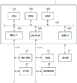
Fig. 2 is a block diagram illustrating one example of a hardware configuration of an image processing apparatus according to one or more embodiments of the subject disclosure.
Fig. 3 illustrates an example of a method for imaging a target object from multiple viewpoints, in accordance with one or more embodiments of the subject disclosure.
Fig. 4 is a block diagram illustrating an example of a logical configuration of an image processing apparatus according to one or more embodiments of the subject disclosure.
Fig. 5 is a flow diagram illustrating a flow of processing by an image processing apparatus in accordance with one or more embodiments of the subject disclosure.
FIG. 6 illustrates an example of processing results in accordance with one or more embodiments of the subject disclosure.
FIG. 7 illustrates an example of processing results in accordance with one or more embodiments of the subject disclosure.
Fig. 8A, 8B, and 8C each illustrate an example of a concave-convex shape in accordance with one or more embodiments of the subject disclosure.
Detailed Description
In the following description, exemplary embodiments of the present disclosure will be described with reference to the accompanying drawings. However, the exemplary embodiments to be described below are not intended to limit the present disclosure, and not a combination of all features to be described in the present exemplary embodiments is essential to the solution of the present disclosure. Similar constructions will be identified with the same reference numerals.
In the following description, a first exemplary embodiment will be described. Fig. 1 is a schematic view of hair. As shown in fig. 1, the shape of the hair can be considered to include two types of asperities: low frequency asperities (hair bundles) and high frequency asperities (one to several hairs). In other words, hair is a three-dimensional object comprising a plurality of strands, each strand comprising a plurality of tiny substances (fibers). The present exemplary embodiment will be described based on the following examples. The region corresponding to the hair in the image is considered to include low-frequency unevenness and high-frequency unevenness (unevenness having a higher frequency than the low-frequency unevenness), and the respective positions (regions) of the low-frequency unevenness and the high-frequency unevenness are identified. Then, an extremely small shape is added at a corresponding position (area) on the three-dimensional shape data representing the overall shape of the hair. The frequency of the asperity is a frequency when the asperity is considered as a wave in which one depression (dent) and one projection (bump) form one cycle.
Fig. 2 shows an example of the hardware configuration of the image processing apparatus 1 according to the present exemplary embodiment. The image processing apparatus 1 is, for example, a computer, and includes a Central Processing Unit (CPU)101, a Read Only Memory (ROM)102, and a Random Access Memory (RAM) 103. The CPU 101 executes an Operating System (OS) and various programs stored in the ROM 102, the Hard Disk Drive (HDD)15, and the like by using the RAM 103 as a work memory. Further, the CPU 101 controls each configuration via a system bus 107. In the case of expanding program codes stored in the ROM 102, the HDD 15, and the like into the RAM 103, processing according to a flowchart to be described below is executed by the CPU 101. Input devices 12 such as a mouse and a keyboard and a printer 13 are connected to a general purpose interface (I/F)104 via a serial bus 11. The HDD 15 and a universal drive 16 are connected to a Serial Advanced Technology Attachment (SATA) I/F105 via a serial bus 14, and the universal drive 16 reads and writes data from and to various recording media. The CPU 101 uses the HDD 15 and various recording media mounted on the general-purpose drive 16 as locations where various data are stored. The display 17 is connected to the video I/F106. The CPU 101 displays a User Interface (UI) provided by the program on the display 17, and receives input received via the input device 12, such as a user instruction.
Fig. 4 is a block diagram showing a functional configuration of the image processing apparatus 1 according to the present exemplary embodiment. The image processing apparatus 1 includes an image acquisition unit 301, a shape acquisition unit 302, a first generation unit 303, a second generation unit 304, and an output unit 305. The image acquisition unit 301 acquires a plurality of pieces of image data acquired by imaging a target object from a plurality of viewpoints. The shape acquisition unit 302 acquires three-dimensional shape data indicating the three-dimensional shape (overall concave-convex shape) of a target object (subject) from a plurality of pieces of image data. The first generation unit 303 identifies the position of a region corresponding to low-frequency unevenness in a region corresponding to hair in an image indicated by image data, and generates first region data indicating the low-frequency unevenness region. Here, the low-frequency unevenness is an overall unevenness shape of each of a plurality of hair strands included in the three-dimensional object. The second generation unit 304 identifies the position of the region corresponding to the high-frequency unevenness in the region corresponding to the hair in the image indicated by the image data, and generates second region data indicating the high-frequency unevenness region. Here, the high-frequency unevenness is an uneven shape of an extremely small substance (fiber) included in each hair bundle. The output unit 305 corrects the three-dimensional shape data by adding a semi-cylindrical concavity and convexity at a region corresponding to the region indicated by the first region data in the three-dimensional shape data. Further, the output unit 305 corrects the three-dimensional shape data by adding a semi-cylindrical concavity and convexity at a region corresponding to the region indicated by the second region data in the three-dimensional shape data. Then, the output unit 305 outputs the corrected three-dimensional shape data to an external apparatus such as the HDD 15.
Next, the process performed by the image processing apparatus 1 will be described with reference to a flowchart shown in fig. 5. The CPU 101 executes the programs stored in the ROM 102 using the RAM 103 as a work memory, whereby the image processing apparatus 1 functions as each block shown in fig. 4 and executes the processing in each step shown in fig. 5. The processing to be described below is not necessarily executed entirely by the CPU 101, and the image processing apparatus 1 may be configured such that a part or all of the processing is executed by one or more processing circuits instead of the CPU 101. In the following description, each step (process) is indicated by adding "S" before the step number.
In step S401, the image acquisition unit 301 acquires a plurality of pieces of image data as processing targets from the external storage device 307 such as the HDD 15, and outputs the acquired data to the shape acquisition unit 302, the first generation unit 303, and the second generation unit 304. The image data acquired here is an image group acquired by imaging the target object 204 from a plurality of viewpoints (a plurality of directions) using the imaging apparatuses 201 to 203 as illustrated in fig. 3. The pieces of image data are output to the shape acquisition unit 302 to acquire the three-dimensional shape of the target object 204. Of the plurality of pieces of image data, one piece of image data (image data obtained by imaging by the imaging apparatus 202) obtained by imaging the target object 204 from the front is output to the first generation unit 303 and the second generation unit 304. The image processing apparatus 1 may be configured to select one piece of image data to be output to the first generation unit 303 and the second generation unit 304 by receiving an instruction from a user.
In step S402, the shape acquisition unit 302 acquires three-dimensional shape data indicating the three-dimensional shape (the overall shape of the hairstyle) of the target object 204 based on the pieces of image data input from the image acquisition unit 301, and outputs the acquired three-dimensional shape data to the output unit 305. One example of a method of generating a three-dimensional shape from an image group acquired by imaging from a plurality of viewpoints is known stereo matching. Stereo matching is a technique of acquiring a three-dimensional shape of an object using a plurality of images taken from different viewpoints. In the present exemplary embodiment, the three-dimensional shape is acquired using the stereo matching. The method for acquiring a three-dimensional shape is not limited to the above-described stereo matching, and the shape acquisition unit 302 may directly acquire three-dimensional shape data acquired by, for example, measurement using a laser scanner or a depth sensor or Computer Graphics (CG) rendering. Further, the shape acquisition unit 302 may acquire the three-dimensional shape data by generating the three-dimensional shape data in advance by the above-described method and storing the generated three-dimensional shape data in the external storage device 307 such as the HDD 15, without generating the three-dimensional shape data in this step. In general, three-dimensional shape data generated in an attempt to acquire a detailed shape such as hair contains a large amount of noise and therefore should be subjected to noise reduction processing (smoothing processing). However, such noise reduction treatment results in an undesirable loss of detailed shape such as hair. On the other hand, the three-dimensional shape data generated by attempting to acquire a rough shape does not contain a detailed shape such as hair. The three-dimensional shape data according to the present exemplary embodiment is data generated by the above-described method and data indicating an overall concave-convex shape that does not include low-frequency concavities and convexities (hair bundles) and high-frequency concavities and convexities (one hair to several hairs).
In step S403, the first generation unit 303 recognizes the position of the low-frequency unevenness by analyzing the image data input from the image acquisition unit 301. In the present exemplary embodiment, the first generation unit 303 identifies the position of low-frequency unevenness in the image data by detecting an edge (luminance change) after applying a smoothing filter to the image data. In order to identify the positions of the low-frequency unevenness, the first generating unit 303 first smoothes the image so as to identify the positions of the low-frequency unevenness having an actual size of about 5mm to 1 cm. In the present exemplary embodiment, a gaussian filter is applied to an imageData is used as processing for smoothing an image (reducing the resolution of the image). Let I denote the luminance value, σ, in the image datagDenotes the standard deviation, and 2w +1 is the filter size, the output luminance value I when applying a gaussian filter to the pixel (u, v)gRepresented by equation (1).

In this equation (1), the standard deviation σgCorresponding to the period of the low frequency asperities. If the data acquired by the image acquisition unit 301 is image data indicating a color signal (red-green-blue (RGB) value), the data is pre-converted into grayscale image data indicating brightness using a known conversion equation before applying a gaussian filter to the image data. Acquisition of grayscale image data may be achieved by preparing grayscale image data in the external storage device 307 in advance and acquiring the grayscale image data by the image acquisition unit 301.
A moving average filter, median filter, or other filter may be used instead of the gaussian filter described above. Output luminance value I in case of using moving average filterARepresented by equation (2).

In addition, the median filter is a filter that: which reorders the luminance values of the pixel of interest and the region around the pixel in descending order and outputs a median value when the luminance values are reordered.
Next, the first generation unit 303 convolves an unsharp mask (unsharp mask) on the image data to which the gaussian filter is applied to identify the position of the low-frequency unevenness. The unsharp mask is one of filters for emphasizing color differences between pixels. Assuming that 2w '+ 1 is the filter size and k denotes the sharpening constant, the luminance value I' of the output image when the unsharp mask is convolved is expressed by equation (3). Typically, the filter size of the unsharp mask approximately matches the filter size of the gaussian filter.
I’(u,v,w’)=I(u,v)+k(I(u,v)-Ig(u,v,w’))...(3)
A Gabor filter may be used instead of an unsharpened mask to detect edges (the location of the asperities may be identified).
Finally, assuming that t represents a threshold value regarding luminance, the first generation unit 303 performs binarization processing on the image data on which the unsharp mask is convolved by equation (4). By this operation, the first generation unit 303 generates first region data (binary data) indicating the position of the low-frequency uneven region (the position corresponding to I ″, 1).

In step S404, the second generation unit 304 identifies the position (period: about 1mm to 5mm) of the high-frequency unevenness by analyzing the image data output from the image acquisition unit 301. In the present exemplary embodiment, the second generation unit 304 identifies the position of high-frequency unevenness in the image data by detecting an edge without applying a smoothing filter to the image data. The second generation unit 304 performs binarization processing to identify the position of high-frequency unevenness, similarly to the first generation unit 303, after directly convolving the unsharp mask on the image data. The second generation unit 304 generates second area data (binary data) indicating the positions of the high-frequency concavo-convex areas based on the recognition result.
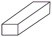
In step S405, the output unit 305 adds the low-frequency unevenness to the three-dimensional image data at a position corresponding to the position of the low-frequency unevenness identified by the first generating unit 303 based on the first region data. In the present exemplary embodiment, as an example shown in fig. 8A, it is assumed that the shape of the added predetermined concavities and convexities is a semi-cylindrical shape. The shape of the concavities and convexities is not limited to the cylindrical shape, and may also be a rod-like shape whose cross section is trapezoidal or rectangular as in the examples shown in fig. 8B and 8C. A method for correcting three-dimensional shape data to incorporate low-frequency unevenness will be described below.
In step S406, the output unit 305 adds the high-frequency unevenness at a position on the three-dimensional image data corresponding to the position of the high-frequency unevenness identified by the second generation unit 304. It is assumed that the shape of the added predetermined unevenness is a semi-cylindrical shape, but the shape may be a rod-like shape having a trapezoidal or rectangular cross section, similarly to step S405. Then, the cycle of the high-frequency unevenness added in step S406 is shorter than the cycle of the low-frequency unevenness. A method for correcting three-dimensional shape data to incorporate high-frequency unevenness will be described below.
In the following description, a process for correcting three-dimensional shape data to incorporate low-frequency unevenness (step S405) will be described. In the present exemplary embodiment, it is assumed that the three-dimensional shape data indicating the overall shape of the hairstyle obtained from stereo matching is depth data. The depth data is data indicating a distance (depth) from an object to the image pickup apparatus. The three-dimensional shape data is not limited to depth data, and may be mesh data, point group data, or other data. Alternatively, the three-dimensional shape data may be data indicating a height from the surface of the image.
First, a normal vector n (n, v) of each pixel is calculated for depth data having a depth d (u, v) at each pixel by equation (5).

In the equation (5), the first and second phases, the gradient is indicated. Next, a normal vector corresponding to a pixel having a pixel value of 1 in the binary data acquired in step S403 is converted. In the binary data I ″, pixels having a pixel value of 1 are searched horizontally row by row from the upper left pixel to the lower right pixel. Then, normal vectors corresponding to respective pixels in the pixel group are converted based on normal vectors (u, v) of pixels located at the center of the group of horizontally connected pixels whose pixel value is 1. At this time, the normal vector is converted by equation (6), wherein it is assumedc denotes the number of connected pixels, (u ', v') denotes the center pixel, and RθA three-dimensional rotation matrix for rotation theta about the y-axis is represented.

For the pixel whose normal vector is converted, a depth is calculated from the normal vector by equation (7), and the depth value is replaced with the depth.

The depth of the region to which the irregularities are added is corrected in this way, whereby low-frequency irregularities are reproduced on the three-dimensional shape data.
Next, a process for correcting the three-dimensional shape data to incorporate high-frequency unevenness (step S406) will be described. Since the high-frequency unevenness is added to the low-frequency unevenness in a superimposed manner, the second region data indicating the high-frequency uneven region is corrected using the first region data indicating the low-frequency uneven region before the high-frequency unevenness is added. For the correction, 0 is set to the pixel value of the pixel in the second region data indicating the high-frequency concavo-convex region (the pixel corresponds to the pixel whose pixel value in the first region data indicating the low-frequency concavo-convex region is 0). This arrangement prevents the high-frequency unevenness from being added at a position where the low-frequency unevenness is not added. After the second region data is corrected, the normal vector is calculated by equation (5), and then, similarly to step S405, the normal vector corresponding to the position of the high-frequency unevenness is converted by equation (6). Then, the depth of the pixel to which the normal vector is converted is calculated by equation (7), and the depth value is replaced with the depth.
In this way, the image processing apparatus 1 according to the present exemplary embodiment detects edges of the image data to which the smoothing filter is applied and the image data to which the smoothing filter is not applied, and identifies the position of the low-frequency unevenness and the position of the high-frequency unevenness. Then, the image processing apparatus 1 according to the present exemplary embodiment reproduces the extremely small unevenness of the hair by correcting the depth of the position indicated by the three-dimensional shape data corresponding to each of the recognized positions. Fig. 6 shows a shape obtained by imaging a wig (hair) as an object having fiber unevenness on the surface thereof and reproducing the wig from the imaging data, thereby making the effect of the present exemplary embodiment easy to understand. From fig. 6, it can be confirmed that both the low frequency shape and the high frequency shape can be reproduced. Furthermore, the treatment may also be applied to fabrics having a fine fiber structure. Fig. 7 shows a shape obtained from the photographed stocking cap. From fig. 7, it can be confirmed that, similarly to the hair, both the low-frequency shape and the high-frequency shape can also be reproduced for the stocking cap. In this way, according to the present exemplary embodiment, the shape of the subject having a microstructure similar to hair can also be reproduced.
[ modified examples ]
In the above-described exemplary embodiment, the extremely small concave-convex shape of the hair is reproduced on the three-dimensional shape data, but the concave-convex shape may also be reproduced by controlling the height of the image surface indicated by the two-dimensional image data. In this case, the image acquisition unit 301 acquires one piece of image data. The image acquisition unit 301 outputs image data to the first generation unit 303 and the second generation unit 304. The shape acquisition unit 302 acquires two-dimensional image data having a height or a depth from a reference plane at each pixel from the external storage device 307. Then, the height or depth at the pixel corresponding to each of the positions identified by the first generation unit 303 and the second generation unit 304 is corrected. By the above processing, an extremely small uneven shape of hair can be reproduced on the two-dimensional image data.
In the above-described exemplary embodiment, the extremely small concave-convex shape of the hair is reproduced on the three-dimensional shape data, but the extremely small concave-convex shape of the hair may be reproduced by a print product by outputting the three-dimensional shape data (or two-dimensional image data) to a printer. In this case, a 3D printer or a printer capable of forming unevenness on the surface of a recording medium can be used as a printer to which data is output.
In the above-described exemplary embodiment, the unevenness is added to the three-dimensional shape data by using the area data identifying the uneven area without any correction to the area data. However, the region data indicating the identified concavo-convex region may contain noise, and therefore, the concavities and convexities may be added after reducing the noise. In this case, noise is reduced before the normal vector is converted by equation (6). One example of a method for reducing noise is a method using the number of connected pixels around a pixel of interest. If the threshold value t' is set for the number of connected pixels adjacent to the pixel of interest, the binarization processing is provided as indicated by equation (8). Equation (8) is an equation prepared to perform the following process: if the number of connected pixels is less than the threshold t', the pixel value is considered as noise.

The noise reduction is not limited to the above one example, and the median filter may be used to reduce the noise.
In the above-described exemplary embodiment, equation (6) is used to convert the normal vector, but the conversion of the normal vector is not limited to the above-described one example. The normal vector may be transformed to reduce the number of connected pixels corresponding to the width of the asperity (thereby making the cross-sectional diameter of the added asperity narrower than the cross-sectional diameter of the identified location) to add a sharper asperity. Assuming that r represents the number of pixels by which the number of connected pixels is reduced, conversion of the normal vector is provided as indicated by equation (9).

In the above-described exemplary embodiments, the shape data is corrected by adding the concavity and convexity having the predetermined specific shape at the corresponding region of the shape data, but the present exemplary embodiment is not limited thereto. For example, the present exemplary embodiment may be configured in the following manner. The size of the overall concave-convex shape (low-frequency concave-convex) of each of a plurality of beams included in the three-dimensional object and the size of the concave-convex shape (high-frequency concave-convex) of the extremely small substance included in each beam are identified based on the acquired image data. Then, the shape data is corrected by adding an uneven shape of a size corresponding to each recognition size to the overall uneven shape of the three-dimensional object.
In the above-described exemplary embodiment, the pixels to be connected are searched horizontally in the binary data, but may be searched vertically.
According to the present disclosure, the fibrous unevenness shape existing on the surface of the object can be reproduced with high accuracy.
Other embodiments
Embodiments of the present disclosure may also be implemented by a computer of a system or apparatus that reads and executes computer-executable instructions (e.g., one or more programs) recorded on a storage medium (also may be more fully referred to as a "non-transitory computer-readable storage medium") to perform the functions of one or more of the above-described embodiments and/or includes one or more circuits (e.g., an application-specific integrated circuit (ASIC)) for performing the functions of one or more of the above-described embodiments, and by a method performed by a computer of a system or apparatus by, for example, reading and executing computer-readable instructions from a storage medium to perform the functions of one or more of the above-described embodiments and/or controlling one or more circuits to perform the functions of one or more of the above-described embodiments. The computer may include one or more processors (e.g., a Central Processing Unit (CPU), Micro Processing Unit (MPU)) and may include a separate computer or a network of separate processors to read out and execute computer-executable instructions. The computer-executable instructions may be provided to the computer from, for example, a network or a storage medium. The storage medium may include, for example, one or more of a hard disk, a Random Access Memory (RAM), a Read Only Memory (ROM), storage of a distributed computing system, an optical disk such as a Compact Disk (CD), a Digital Versatile Disk (DVD), or a blu-ray disk (BD) (registered trademark), a flash memory device, a memory card, and the like.
The embodiments of the present invention can also be realized by a method in which software (programs) that perform the functions of the above-described embodiments are supplied to a system or an apparatus through a network or various storage media, and a computer or a Central Processing Unit (CPU), a Micro Processing Unit (MPU) of the system or the apparatus reads out and executes the methods of the programs.
While the present disclosure has been described with reference to exemplary embodiments, it is to be understood that the disclosure is not limited to the disclosed exemplary embodiments. The scope of the following claims is to be accorded the broadest interpretation so as to encompass all such modifications and equivalent structures and functions.
Claims (20)
1. An image processing apparatus configured to output data indicating a shape of a three-dimensional object including a plurality of bundles, each bundle of the plurality of bundles including a plurality of fibers, the image processing apparatus comprising:
a first acquisition unit configured to acquire image data acquired by imaging the three-dimensional object;
a second acquisition unit configured to acquire shape data indicating an overall concave-convex shape of the three-dimensional object;
a generation unit configured to generate first area data indicating an area corresponding to an overall concave-convex shape of each of the plurality of bundles included in the three-dimensional object and second area data indicating an area corresponding to a concave-convex shape of fibers included in each bundle by analyzing image data; and
an output unit configured to output shape data after correcting the shape data by adding an overall concave-convex shape of each of the plurality of bundles included in the three-dimensional object to an overall concave-convex shape of the three-dimensional object and adding a concave-convex shape of fibers included in each bundle to an overall concave-convex shape of each of the plurality of bundles included in the three-dimensional object based on the first area data and the second area data.
2. The image processing apparatus according to claim 1,
wherein the first acquisition unit acquires a plurality of pieces of image data acquired by imaging the three-dimensional object from a plurality of directions, and
wherein the second acquisition unit generates and acquires shape data based on the plurality of pieces of image data.
3. The image processing apparatus according to claim 1, wherein the shape data is data acquired by measurement using a laser scanner or a depth sensor, or by CG rendering.
4. The image processing apparatus according to claim 1, wherein the shape data is two-dimensional image data indicating a height or a depth of the three-dimensional object from a reference plane as an overall concavo-convex shape of the three-dimensional object.
5. The image processing apparatus according to claim 1, wherein the generation unit identifies the region corresponding to the overall concave-convex shape of each of the plurality of bundles included in the three-dimensional object by detecting a change in luminance of image data after smoothing the image data, and identifies the region corresponding to the concave-convex shape of the fibers included in each bundle by detecting a change in luminance of the image data without smoothing the image data.
6. The image processing apparatus according to claim 5, wherein the generation unit identifies a region corresponding to an overall concavo-convex shape of each of the plurality of beams included in the three-dimensional object after smoothing the image data using a Gaussian filter.
7. The image processing apparatus according to claim 5, wherein the generation unit identifies a region corresponding to an overall concavo-convex shape of each of the plurality of beams included in the three-dimensional object after smoothing the image data using a moving average filter or a median filter.
8. The image processing apparatus according to claim 5, wherein the generation unit detects a change in luminance using an unsharp mask.
9. The image processing apparatus according to claim 5, wherein the generation unit detects a change in luminance using a Gabor filter.
10. The image processing apparatus according to claim 1,
wherein the shape data is data indicating a depth,
wherein the image processing apparatus further comprises:
a calculation unit configured to calculate a normal vector on a surface of the three-dimensional object corresponding to a depth indicated by the shape data; and
a conversion unit configured to convert the normal vector so that a predetermined shape is acquired as a shape of a region in the shape data, the region corresponding to each of a region indicated by the first region data corresponding to an overall concave-convex shape of each of the plurality of bundles included in the three-dimensional object and a region indicated by the second region data corresponding to a concave-convex shape of fibers included in each of the bundles, and
wherein the output unit corrects the shape data by calculating a depth from the normal vector converted by the conversion unit and replacing the depth indicated by the shape data with the calculated depth.
11. The image processing apparatus according to claim 10, wherein the predetermined shape is a semi-cylindrical shape.
12. The image processing apparatus according to claim 10, wherein the predetermined shape is a rod-like shape whose cross section is a trapezoid or a rectangle.
13. The image processing apparatus according to claim 1, wherein the output unit corrects the shape data by adding, to the overall concave-convex shape of the three-dimensional object, a concave-convex shape having a size corresponding to each of the size of the overall concave-convex shape of each of the plurality of bundles included in the three-dimensional object and the size of the concave-convex shape of the fibers included in each bundle, which is identified based on the image data.
14. The image processing apparatus according to claim 1, wherein the three-dimensional object is hair.
15. The image processing apparatus according to claim 1, wherein the three-dimensional object is a fabric.
16. The image processing apparatus according to claim 1, wherein the overall concave-convex shape of each of the plurality of bundles included in the three-dimensional object includes concave-convex having a period of 5mm to 1cm, and the concave-convex shape of the fiber included in each bundle includes concave-convex having a period of 1mm to 5 mm.
17. The image processing apparatus according to claim 1, further comprising a reduction unit configured to reduce noise included in the first area data and the second area data,
wherein the output unit corrects the shape data based on the first area data and the second area data in which noise is reduced by the reduction unit.
18. The image processing apparatus according to claim 10, wherein the conversion unit converts the normal vector so that a cross-sectional diameter of the predetermined shape is narrower than regions in the shape data corresponding to each of a region indicated by the first region data corresponding to an overall concavo-convex shape of each of the plurality of bundles included in the three-dimensional object and a region indicated by the second region data corresponding to a concavo-convex shape of fibers included in each bundle.
19. An image processing method for outputting data indicative of a shape of a three-dimensional object comprising a plurality of bundles, each bundle of the plurality of bundles comprising a plurality of fibers, the image processing method comprising:
acquiring image data acquired by imaging the three-dimensional object as first acquisition;
acquiring, as a second acquisition, shape data indicating an overall concave-convex shape of the three-dimensional object;
generating first area data indicating an area corresponding to an overall concave-convex shape of each of the plurality of bundles included in the three-dimensional object and second area data indicating an area corresponding to a concave-convex shape of fibers included in each bundle by analyzing the image data; and
outputting shape data after correcting the shape data by adding an overall concave-convex shape of each of the plurality of bundles included in the three-dimensional object to an overall concave-convex shape of the three-dimensional object and adding a concave-convex shape of fibers included in each bundle to an overall concave-convex shape of each of the plurality of bundles included in the three-dimensional object based on the first area data and the second area data.
20. A non-transitory computer-readable storage medium storing instructions that, when executed by a computer, cause the computer to perform a method comprising:
acquiring, as a first acquisition, image data acquired by imaging a three-dimensional object including a plurality of bundles each including a plurality of fibers;
acquiring, as a second acquisition, shape data indicating an overall concave-convex shape of the three-dimensional object;
generating first area data indicating an area corresponding to an overall concave-convex shape of each of the plurality of bundles included in the three-dimensional object and second area data indicating an area corresponding to a concave-convex shape of fibers included in each bundle by analyzing the image data; and
outputting shape data after correcting the shape data by adding an overall concave-convex shape of each of the plurality of bundles included in the three-dimensional object to an overall concave-convex shape of the three-dimensional object and adding a concave-convex shape of fibers included in each bundle to an overall concave-convex shape of each of the plurality of bundles included in the three-dimensional object based on the first area data and the second area data.
Applications Claiming Priority (2)
| Application Number | Priority Date | Filing Date | Title |
|---|---|---|---|
| JP2016-188407 | 2016-09-27 | ||
| JP2016188407A JP6800676B2 (en) | 2016-09-27 | 2016-09-27 | Image processing equipment, image processing methods and programs |
Publications (2)
| Publication Number | Publication Date |
|---|---|
| CN107871326A CN107871326A (en) | 2018-04-03 |
| CN107871326B true CN107871326B (en) | 2021-08-24 |
Family
ID=61686402
Family Applications (1)
| Application Number | Title | Priority Date | Filing Date |
|---|---|---|---|
| CN201710872368.0A Active CN107871326B (en) | 2016-09-27 | 2017-09-25 | Image processing apparatus, image processing method, and storage medium |
Country Status (4)
| Country | Link |
|---|---|
| US (1) | US10430960B2 (en) |
| JP (1) | JP6800676B2 (en) |
| KR (1) | KR102255148B1 (en) |
| CN (1) | CN107871326B (en) |
Families Citing this family (3)
| Publication number | Priority date | Publication date | Assignee | Title |
|---|---|---|---|---|
| US11830131B2 (en) * | 2018-02-06 | 2023-11-28 | Veo Robotics, Inc. | Workpiece sensing for process management and orchestration |
| US11347056B2 (en) * | 2018-08-22 | 2022-05-31 | Microsoft Technology Licensing, Llc | Foveated color correction to improve color uniformity of head-mounted displays |
| US11423515B2 (en) | 2019-11-06 | 2022-08-23 | Canon Kabushiki Kaisha | Image processing apparatus |
Citations (5)
| Publication number | Priority date | Publication date | Assignee | Title |
|---|---|---|---|---|
| CN1137966A (en) * | 1995-04-01 | 1996-12-18 | 株式会社珀蒂奥 | Three-dimensional processing device |
| CN104883946A (en) * | 2012-12-20 | 2015-09-02 | 奥林巴斯株式会社 | Image processing apparatus, electronic device, endoscope apparatus, program, and image processing method |
| CN105654464A (en) * | 2014-11-28 | 2016-06-08 | 佳能株式会社 | Image processing apparatus and image processing method |
| WO2016098298A1 (en) * | 2014-12-19 | 2016-06-23 | Canon Kabushiki Kaisha | Image processing apparatus and image processing method |
| US20160247271A1 (en) * | 2013-09-30 | 2016-08-25 | Ihi Corporation | Image analyzing apparatus and program |
Family Cites Families (7)
| Publication number | Priority date | Publication date | Assignee | Title |
|---|---|---|---|---|
| JPH11328444A (en) * | 1998-05-20 | 1999-11-30 | Minolta Co Ltd | Modeling system |
| JP3832065B2 (en) * | 1997-12-26 | 2006-10-11 | コニカミノルタホールディングス株式会社 | 3D shape data processing device |
| JP2000339498A (en) * | 1999-05-31 | 2000-12-08 | Minolta Co Ltd | Three-dimensional shape data processor |
| US8428382B2 (en) * | 2007-02-16 | 2013-04-23 | Kao Corporation | Hair image display method and display apparatus |
| US8884980B2 (en) * | 2010-09-24 | 2014-11-11 | Taaz, Inc. | System and method for changing hair color in digital images |
| US20130170715A1 (en) * | 2012-01-03 | 2013-07-04 | Waymon B. Reed | Garment modeling simulation system and process |
| JP5949331B2 (en) * | 2012-08-30 | 2016-07-06 | カシオ計算機株式会社 | Image generating apparatus, image generating method, and program |
-
2016
- 2016-09-27 JP JP2016188407A patent/JP6800676B2/en active Active
-
2017
- 2017-09-15 KR KR1020170118304A patent/KR102255148B1/en active IP Right Grant
- 2017-09-25 CN CN201710872368.0A patent/CN107871326B/en active Active
- 2017-09-25 US US15/714,301 patent/US10430960B2/en active Active
Patent Citations (5)
| Publication number | Priority date | Publication date | Assignee | Title |
|---|---|---|---|---|
| CN1137966A (en) * | 1995-04-01 | 1996-12-18 | 株式会社珀蒂奥 | Three-dimensional processing device |
| CN104883946A (en) * | 2012-12-20 | 2015-09-02 | 奥林巴斯株式会社 | Image processing apparatus, electronic device, endoscope apparatus, program, and image processing method |
| US20160247271A1 (en) * | 2013-09-30 | 2016-08-25 | Ihi Corporation | Image analyzing apparatus and program |
| CN105654464A (en) * | 2014-11-28 | 2016-06-08 | 佳能株式会社 | Image processing apparatus and image processing method |
| WO2016098298A1 (en) * | 2014-12-19 | 2016-06-23 | Canon Kabushiki Kaisha | Image processing apparatus and image processing method |
Also Published As
| Publication number | Publication date |
|---|---|
| JP6800676B2 (en) | 2020-12-16 |
| KR20180034237A (en) | 2018-04-04 |
| CN107871326A (en) | 2018-04-03 |
| JP2018055258A (en) | 2018-04-05 |
| US10430960B2 (en) | 2019-10-01 |
| US20180089850A1 (en) | 2018-03-29 |
| KR102255148B1 (en) | 2021-05-24 |
Similar Documents
| Publication | Publication Date | Title |
|---|---|---|
| CN108765273B (en) | Virtual face-lifting method and device for face photographing | |
| CN109191584B (en) | Three-dimensional model processing method and device, electronic equipment and readable storage medium | |
| US8805077B2 (en) | Subject region detecting apparatus | |
| CN109102559B (en) | Three-dimensional model processing method and device | |
| US11153552B2 (en) | Image processing apparatus, image processing method and non-transitory computer-readable storage medium | |
| JP5949331B2 (en) | Image generating apparatus, image generating method, and program | |
| CN107871326B (en) | Image processing apparatus, image processing method, and storage medium | |
| US8923610B2 (en) | Image processing apparatus, image processing method, and computer readable medium | |
| JP2020010146A (en) | Image processing system, image processing method, and program | |
| US9762773B2 (en) | Image processing apparatus and method for increasing sharpness of images | |
| CN109191393B (en) | Three-dimensional model-based beauty method | |
| US20180336688A1 (en) | Image processing apparatus and image processing method, and storage medium | |
| KR20160110038A (en) | Image processing apparatus and image processing method | |
| Ling et al. | Image quality assessment for DIBR synthesized views using elastic metric | |
| JP6185807B2 (en) | Wrinkle state analysis method and wrinkle state analyzer | |
| US11798227B2 (en) | Image processing apparatus and image processing method | |
| JP2012048326A (en) | Image processor and program | |
| JP5029545B2 (en) | Image processing method and apparatus | |
| JP6467817B2 (en) | Image processing apparatus, image processing method, and program | |
| JP6287170B2 (en) | Eyebrow generating device, eyebrow generating method and program | |
| US20210174541A1 (en) | Image-capturing control apparatus, image-capturing control method, and storage medium | |
| JP4025656B2 (en) | Contour line segment extraction method, contour line segment extraction device, contour line segment extraction program, and recording medium recording the program | |
| Hsiao et al. | Using Regularity Unit As Guidance For Summarization-Based Image Resizing | |
| JP6248863B2 (en) | Image processing device | |
| Menaga et al. | Identification of Facial Retouching Using Supervised Deep Learning Algorithm |
Legal Events
| Date | Code | Title | Description |
|---|---|---|---|
| PB01 | Publication | ||
| PB01 | Publication | ||
| SE01 | Entry into force of request for substantive examination | ||
| SE01 | Entry into force of request for substantive examination | ||
| GR01 | Patent grant | ||
| GR01 | Patent grant |