CN107852377B - System and method for supporting scalable representation of switch port conditions in a high performance computing environment - Google Patents
System and method for supporting scalable representation of switch port conditions in a high performance computing environment Download PDFInfo
- Publication number
- CN107852377B CN107852377B CN201780002356.0A CN201780002356A CN107852377B CN 107852377 B CN107852377 B CN 107852377B CN 201780002356 A CN201780002356 A CN 201780002356A CN 107852377 B CN107852377 B CN 107852377B
- Authority
- CN
- China
- Prior art keywords
- switch
- switches
- port
- ports
- subnet
- Prior art date
- Legal status (The legal status is an assumption and is not a legal conclusion. Google has not performed a legal analysis and makes no representation as to the accuracy of the status listed.)
- Active
Links
Images


Classifications
-
- H—ELECTRICITY
- H04—ELECTRIC COMMUNICATION TECHNIQUE
- H04L—TRANSMISSION OF DIGITAL INFORMATION, e.g. TELEGRAPHIC COMMUNICATION
- H04L49/00—Packet switching elements
- H04L49/25—Routing or path finding in a switch fabric
-
- G—PHYSICS
- G06—COMPUTING; CALCULATING OR COUNTING
- G06F—ELECTRIC DIGITAL DATA PROCESSING
- G06F16/00—Information retrieval; Database structures therefor; File system structures therefor
- G06F16/20—Information retrieval; Database structures therefor; File system structures therefor of structured data, e.g. relational data
- G06F16/22—Indexing; Data structures therefor; Storage structures
- G06F16/2228—Indexing structures
- G06F16/2237—Vectors, bitmaps or matrices
-
- G—PHYSICS
- G06—COMPUTING; CALCULATING OR COUNTING
- G06F—ELECTRIC DIGITAL DATA PROCESSING
- G06F9/00—Arrangements for program control, e.g. control units
- G06F9/06—Arrangements for program control, e.g. control units using stored programs, i.e. using an internal store of processing equipment to receive or retain programs
- G06F9/44—Arrangements for executing specific programs
- G06F9/451—Execution arrangements for user interfaces
-
- G—PHYSICS
- G06—COMPUTING; CALCULATING OR COUNTING
- G06F—ELECTRIC DIGITAL DATA PROCESSING
- G06F9/00—Arrangements for program control, e.g. control units
- G06F9/06—Arrangements for program control, e.g. control units using stored programs, i.e. using an internal store of processing equipment to receive or retain programs
- G06F9/44—Arrangements for executing specific programs
- G06F9/455—Emulation; Interpretation; Software simulation, e.g. virtualisation or emulation of application or operating system execution engines
- G06F9/45533—Hypervisors; Virtual machine monitors
- G06F9/45558—Hypervisor-specific management and integration aspects
-
- H—ELECTRICITY
- H04—ELECTRIC COMMUNICATION TECHNIQUE
- H04L—TRANSMISSION OF DIGITAL INFORMATION, e.g. TELEGRAPHIC COMMUNICATION
- H04L41/00—Arrangements for maintenance, administration or management of data switching networks, e.g. of packet switching networks
- H04L41/04—Network management architectures or arrangements
- H04L41/046—Network management architectures or arrangements comprising network management agents or mobile agents therefor
-
- H—ELECTRICITY
- H04—ELECTRIC COMMUNICATION TECHNIQUE
- H04L—TRANSMISSION OF DIGITAL INFORMATION, e.g. TELEGRAPHIC COMMUNICATION
- H04L41/00—Arrangements for maintenance, administration or management of data switching networks, e.g. of packet switching networks
- H04L41/08—Configuration management of networks or network elements
- H04L41/0803—Configuration setting
-
- H—ELECTRICITY
- H04—ELECTRIC COMMUNICATION TECHNIQUE
- H04L—TRANSMISSION OF DIGITAL INFORMATION, e.g. TELEGRAPHIC COMMUNICATION
- H04L41/00—Arrangements for maintenance, administration or management of data switching networks, e.g. of packet switching networks
- H04L41/08—Configuration management of networks or network elements
- H04L41/085—Retrieval of network configuration; Tracking network configuration history
- H04L41/0853—Retrieval of network configuration; Tracking network configuration history by actively collecting configuration information or by backing up configuration information
-
- H—ELECTRICITY
- H04—ELECTRIC COMMUNICATION TECHNIQUE
- H04L—TRANSMISSION OF DIGITAL INFORMATION, e.g. TELEGRAPHIC COMMUNICATION
- H04L41/00—Arrangements for maintenance, administration or management of data switching networks, e.g. of packet switching networks
- H04L41/12—Discovery or management of network topologies
-
- H—ELECTRICITY
- H04—ELECTRIC COMMUNICATION TECHNIQUE
- H04L—TRANSMISSION OF DIGITAL INFORMATION, e.g. TELEGRAPHIC COMMUNICATION
- H04L41/00—Arrangements for maintenance, administration or management of data switching networks, e.g. of packet switching networks
- H04L41/14—Network analysis or design
-
- H—ELECTRICITY
- H04—ELECTRIC COMMUNICATION TECHNIQUE
- H04L—TRANSMISSION OF DIGITAL INFORMATION, e.g. TELEGRAPHIC COMMUNICATION
- H04L43/00—Arrangements for monitoring or testing data switching networks
- H04L43/08—Monitoring or testing based on specific metrics, e.g. QoS, energy consumption or environmental parameters
- H04L43/0805—Monitoring or testing based on specific metrics, e.g. QoS, energy consumption or environmental parameters by checking availability
- H04L43/0817—Monitoring or testing based on specific metrics, e.g. QoS, energy consumption or environmental parameters by checking availability by checking functioning
-
- H—ELECTRICITY
- H04—ELECTRIC COMMUNICATION TECHNIQUE
- H04L—TRANSMISSION OF DIGITAL INFORMATION, e.g. TELEGRAPHIC COMMUNICATION
- H04L43/00—Arrangements for monitoring or testing data switching networks
- H04L43/08—Monitoring or testing based on specific metrics, e.g. QoS, energy consumption or environmental parameters
- H04L43/0823—Errors, e.g. transmission errors
-
- H—ELECTRICITY
- H04—ELECTRIC COMMUNICATION TECHNIQUE
- H04L—TRANSMISSION OF DIGITAL INFORMATION, e.g. TELEGRAPHIC COMMUNICATION
- H04L43/00—Arrangements for monitoring or testing data switching networks
- H04L43/08—Monitoring or testing based on specific metrics, e.g. QoS, energy consumption or environmental parameters
- H04L43/0876—Network utilisation, e.g. volume of load or congestion level
- H04L43/0882—Utilisation of link capacity
-
- H—ELECTRICITY
- H04—ELECTRIC COMMUNICATION TECHNIQUE
- H04L—TRANSMISSION OF DIGITAL INFORMATION, e.g. TELEGRAPHIC COMMUNICATION
- H04L45/00—Routing or path finding of packets in data switching networks
- H04L45/02—Topology update or discovery
-
- H—ELECTRICITY
- H04—ELECTRIC COMMUNICATION TECHNIQUE
- H04L—TRANSMISSION OF DIGITAL INFORMATION, e.g. TELEGRAPHIC COMMUNICATION
- H04L45/00—Routing or path finding of packets in data switching networks
- H04L45/48—Routing tree calculation
-
- H—ELECTRICITY
- H04—ELECTRIC COMMUNICATION TECHNIQUE
- H04L—TRANSMISSION OF DIGITAL INFORMATION, e.g. TELEGRAPHIC COMMUNICATION
- H04L49/00—Packet switching elements
- H04L49/10—Packet switching elements characterised by the switching fabric construction
-
- H—ELECTRICITY
- H04—ELECTRIC COMMUNICATION TECHNIQUE
- H04L—TRANSMISSION OF DIGITAL INFORMATION, e.g. TELEGRAPHIC COMMUNICATION
- H04L49/00—Packet switching elements
- H04L49/10—Packet switching elements characterised by the switching fabric construction
- H04L49/113—Arrangements for redundant switching, e.g. using parallel planes
- H04L49/118—Address processing within a device, e.g. using internal ID or tags for routing within a switch
-
- H—ELECTRICITY
- H04—ELECTRIC COMMUNICATION TECHNIQUE
- H04L—TRANSMISSION OF DIGITAL INFORMATION, e.g. TELEGRAPHIC COMMUNICATION
- H04L49/00—Packet switching elements
- H04L49/15—Interconnection of switching modules
-
- H—ELECTRICITY
- H04—ELECTRIC COMMUNICATION TECHNIQUE
- H04L—TRANSMISSION OF DIGITAL INFORMATION, e.g. TELEGRAPHIC COMMUNICATION
- H04L49/00—Packet switching elements
- H04L49/30—Peripheral units, e.g. input or output ports
-
- H—ELECTRICITY
- H04—ELECTRIC COMMUNICATION TECHNIQUE
- H04L—TRANSMISSION OF DIGITAL INFORMATION, e.g. TELEGRAPHIC COMMUNICATION
- H04L49/00—Packet switching elements
- H04L49/35—Switches specially adapted for specific applications
- H04L49/356—Switches specially adapted for specific applications for storage area networks
- H04L49/358—Infiniband Switches
-
- H—ELECTRICITY
- H04—ELECTRIC COMMUNICATION TECHNIQUE
- H04L—TRANSMISSION OF DIGITAL INFORMATION, e.g. TELEGRAPHIC COMMUNICATION
- H04L63/00—Network architectures or network communication protocols for network security
- H04L63/02—Network architectures or network communication protocols for network security for separating internal from external traffic, e.g. firewalls
- H04L63/0227—Filtering policies
- H04L63/0236—Filtering by address, protocol, port number or service, e.g. IP-address or URL
-
- H—ELECTRICITY
- H04—ELECTRIC COMMUNICATION TECHNIQUE
- H04L—TRANSMISSION OF DIGITAL INFORMATION, e.g. TELEGRAPHIC COMMUNICATION
- H04L63/00—Network architectures or network communication protocols for network security
- H04L63/02—Network architectures or network communication protocols for network security for separating internal from external traffic, e.g. firewalls
- H04L63/0227—Filtering policies
- H04L63/0254—Stateful filtering
-
- H—ELECTRICITY
- H04—ELECTRIC COMMUNICATION TECHNIQUE
- H04L—TRANSMISSION OF DIGITAL INFORMATION, e.g. TELEGRAPHIC COMMUNICATION
- H04L67/00—Network arrangements or protocols for supporting network services or applications
- H04L67/01—Protocols
- H04L67/10—Protocols in which an application is distributed across nodes in the network
- H04L67/1097—Protocols in which an application is distributed across nodes in the network for distributed storage of data in networks, e.g. transport arrangements for network file system [NFS], storage area networks [SAN] or network attached storage [NAS]
-
- G—PHYSICS
- G06—COMPUTING; CALCULATING OR COUNTING
- G06F—ELECTRIC DIGITAL DATA PROCESSING
- G06F9/00—Arrangements for program control, e.g. control units
- G06F9/06—Arrangements for program control, e.g. control units using stored programs, i.e. using an internal store of processing equipment to receive or retain programs
- G06F9/44—Arrangements for executing specific programs
- G06F9/455—Emulation; Interpretation; Software simulation, e.g. virtualisation or emulation of application or operating system execution engines
- G06F9/45533—Hypervisors; Virtual machine monitors
- G06F9/45558—Hypervisor-specific management and integration aspects
- G06F2009/45579—I/O management, e.g. providing access to device drivers or storage
-
- G—PHYSICS
- G06—COMPUTING; CALCULATING OR COUNTING
- G06F—ELECTRIC DIGITAL DATA PROCESSING
- G06F9/00—Arrangements for program control, e.g. control units
- G06F9/06—Arrangements for program control, e.g. control units using stored programs, i.e. using an internal store of processing equipment to receive or retain programs
- G06F9/44—Arrangements for executing specific programs
- G06F9/455—Emulation; Interpretation; Software simulation, e.g. virtualisation or emulation of application or operating system execution engines
- G06F9/45533—Hypervisors; Virtual machine monitors
- G06F9/45558—Hypervisor-specific management and integration aspects
- G06F2009/45595—Network integration; Enabling network access in virtual machine instances
-
- H—ELECTRICITY
- H04—ELECTRIC COMMUNICATION TECHNIQUE
- H04L—TRANSMISSION OF DIGITAL INFORMATION, e.g. TELEGRAPHIC COMMUNICATION
- H04L12/00—Data switching networks
- H04L12/28—Data switching networks characterised by path configuration, e.g. LAN [Local Area Networks] or WAN [Wide Area Networks]
- H04L12/44—Star or tree networks
-
- H—ELECTRICITY
- H04—ELECTRIC COMMUNICATION TECHNIQUE
- H04L—TRANSMISSION OF DIGITAL INFORMATION, e.g. TELEGRAPHIC COMMUNICATION
- H04L49/00—Packet switching elements
- H04L49/10—Packet switching elements characterised by the switching fabric construction
- H04L49/111—Switch interfaces, e.g. port details
-
- H—ELECTRICITY
- H04—ELECTRIC COMMUNICATION TECHNIQUE
- H04L—TRANSMISSION OF DIGITAL INFORMATION, e.g. TELEGRAPHIC COMMUNICATION
- H04L49/00—Packet switching elements
- H04L49/70—Virtual switches
-
- H—ELECTRICITY
- H04—ELECTRIC COMMUNICATION TECHNIQUE
- H04L—TRANSMISSION OF DIGITAL INFORMATION, e.g. TELEGRAPHIC COMMUNICATION
- H04L63/00—Network architectures or network communication protocols for network security
- H04L63/12—Applying verification of the received information
-
- H—ELECTRICITY
- H04—ELECTRIC COMMUNICATION TECHNIQUE
- H04L—TRANSMISSION OF DIGITAL INFORMATION, e.g. TELEGRAPHIC COMMUNICATION
- H04L63/00—Network architectures or network communication protocols for network security
- H04L63/14—Network architectures or network communication protocols for network security for detecting or protecting against malicious traffic
- H04L63/1441—Countermeasures against malicious traffic
-
- H—ELECTRICITY
- H04—ELECTRIC COMMUNICATION TECHNIQUE
- H04L—TRANSMISSION OF DIGITAL INFORMATION, e.g. TELEGRAPHIC COMMUNICATION
- H04L63/00—Network architectures or network communication protocols for network security
- H04L63/20—Network architectures or network communication protocols for network security for managing network security; network security policies in general
Abstract
Systems and methods for supporting scalable representation of link stability and availability in a high performance computing environment. The method may provide an attribute at each node in the subnet, wherein the attribute provides a single location at each node for the subnet manager to query the stability and availability of each link connected to the queried node. This attribute may be populated and maintained by a subnet management agent residing at the node.
Description
Copyright notice
A portion of the disclosure of this patent document contains material which is subject to copyright protection. The copyright owner has no objection to the facsimile reproduction by anyone of the patent document or the patent disclosure, as it appears in the patent and trademark office patent file or records, but otherwise reserves all copyright rights whatsoever.
Technical Field
The present invention relates generally to computer systems, and more particularly to supporting scalable representation (scalable representation) of switch port conditions in a high performance computing environment.
Background
As larger cloud computing architectures are introduced, the performance and management bottlenecks associated with traditional networks and storage become significant issues. There is an increasing interest in using high performance lossless interconnects such as infiniband (ib) technology as the basis for cloud computing architectures. This is the general field that embodiments of the present invention are intended to address.
Disclosure of Invention
Systems and methods for supporting scalable representation of switch port conditions in a high performance computing environment are described herein. A method may provide, at one or more computers comprising one or more microprocessors, at least one subnet comprising: one or more switches, a plurality of host channel adapters, a plurality of end nodes, and a subnet manager. The one or more switches comprise at least a leaf switch, wherein each switch of the one or more switches comprises a plurality of ports, and wherein each switch of the one or more switches comprises at least one attribute; wherein the plurality of host channel adapters are interconnected via the one or more switches; each end node of the plurality of end nodes is associated with at least one host channel adapter of a plurality of host channel adapters; the subnet manager runs on one of the one or more switches or one of the plurality of host channel adapters. The method may associate each of a plurality of ports on one or more switches with a switch port status. The method may represent each switch port condition associated with each of a plurality of ports on each switch in at least one attribute at the associated switch.
Systems and methods for supporting link stability and availability attributes in a high performance computing environment are described herein. An example method may provide, at one or more computers comprising one or more microprocessors, at least one subnet, at least one or more switches, the one or more switches comprising at least a leaf switch, wherein each switch of the one or more switches comprises a plurality of ports, and wherein each switch of the one or more switches comprises at least one attribute; a plurality of host channel adapters, wherein the plurality of host channel adapters are interconnected via one or more switches; a plurality of end nodes, each of the plurality of end nodes associated with at least one host channel adapter of a plurality of host channel adapters; and a subnet manager that runs on one of the one or more switches or one of the plurality of host channel adapters. The method may provide at least one attribute at each of the one or more switches. The method may provide a subnet management agent of a plurality of Subnet Management Agents (SMAs) at a switch of the one or more switches. The method may monitor, by the SMA of the switch of the one or more switches, at least one of link stability at each of the plurality of ports of the switch and link availability at each of the plurality of ports at the switch.
According to an embodiment, one or more of the plurality of host channel adapters may include at least one virtual function, at least one virtual switch, and at least one physical function. The plurality of end nodes may comprise physical hosts, virtual machines, or a combination of physical hosts and virtual machines, wherein a virtual machine is associated with at least one virtual function.
Drawings
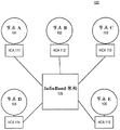
Fig. 1 shows a diagram of an InfiniBand environment according to an embodiment.
FIG. 2 shows a diagram of a partitioned cluster environment, according to an embodiment.
FIG. 3 shows a diagram of a tree topology in a network environment, according to an embodiment.
FIG. 4 illustrates an exemplary shared port architecture, according to an embodiment.
Figure 5 illustrates an exemplary vSwitch architecture, according to an embodiment.
Fig. 6 illustrates an exemplary vPort architecture in accordance with embodiments.
Fig. 7 illustrates an exemplary vSwitch architecture with prepopulated LIDs, according to an embodiment.
Fig. 8 illustrates an exemplary vSwitch architecture with dynamic LID assignment, according to embodiments.
Fig. 9 illustrates an exemplary vSwitch architecture with a vSwitch with dynamic LID assignment and prepopulated LIDs, according to embodiments.
Fig. 10 illustrates an exemplary multi-subnet InfiniBand architecture, according to an embodiment.
Fig. 11 illustrates a scalable representation of switch port conditions according to an embodiment.
Fig. 12 illustrates a scalable representation of link conditions according to an embodiment.
Fig. 13 is a flow diagram of a method for supporting scalable representation of switch port conditions in a high performance computing environment, according to an embodiment.
Fig. 14 is a flow diagram of a method for supporting scalable representation of switch port conditions in a high performance computing environment, according to an embodiment.
Fig. 15 illustrates a scalable representation of link stability according to an embodiment.
Fig. 16 illustrates a scalable representation of link availability according to an embodiment.
Fig. 17 is a flow diagram of an exemplary method for supporting scalable representation of link stability and availability in a high performance computing environment, according to an embodiment.
Detailed Description
The present invention is illustrated by way of example, and not by way of limitation, in the figures of the accompanying drawings and in which like reference numerals refer to similar elements. It should be noted that references to "an" or "some" embodiment in this disclosure are not necessarily to the same embodiment, and such references mean at least one. While specific implementations are discussed, it should be understood that these specific implementations are provided for illustrative purposes only. A person skilled in the relevant art will recognize that other components and configurations may be used without parting from the scope and spirit of the invention.
Common reference numerals may be used throughout the drawings and detailed description to refer to like elements; thus, if elements are described elsewhere, the reference numbers used in the figures may or may not be referred to in the detailed description specific to the figure.
Described herein are systems and methods for supporting scalable representation of switch port conditions in a high performance computing environment.
The following description of the invention uses InfiniBandTM(IB) networks are an example of high performance networks. Throughout the following description, reference may be made to InfiniBandTMSpecification (also variously referred to as InfiniBand specification, IB specification, or legacy IB specification). Such references are understood to refer to those published 3 months 2015 available at http:// www.inifinibandta.org Trade association architecture specification (
 Trade Association Architecture Specification)
 volume 1, version 1.3, the entire contents of which are incorporated herein by reference. It will be clear to those skilled in the art that other types of high performance networks may be used without limitation. The following description also uses a fat-tree topology as an example of an architectural topology. It will be clear to those skilled in the art that other types of architectural topologies may be used without limitation.
To meet the demands of the current era (e.g., the Exascale era) on the cloud, it is desirable for virtual machines to be able to take advantage of low-overhead network communication paradigms (paradigm) such as Remote Direct Memory Access (RDMA). RDMA bypasses the OS stack and communicates directly with the hardware, so pass-through techniques like Single root I/O virtualization (SR-IOV) network adapters can be used. According to embodiments, a virtual switch (vSwitch) SR-IOV architecture may be provided for applicability in high performance lossless interconnection networks. Since network reconfiguration time is crucial to making live migration a practical option, a scalable and topology-independent (topology-aware) dynamic reconfiguration mechanism may be provided in addition to the network architecture.
And in addition, according to embodiments, routing policies for virtualized environments using vSwitch may be provided, and efficient routing algorithms for network topologies (e.g., fat-tree topologies) may be provided. The dynamic reconfiguration mechanism can be further fine-tuned to minimize the overhead imposed in the fat tree.
According to embodiments of the invention, virtualization may be beneficial for efficient resource utilization and flexible resource allocation in cloud computing. Live migration makes it possible to optimize resource usage by moving Virtual Machines (VMs) between physical servers in an application transparent manner. Thus, virtualization can achieve integration, on-demand provisioning of resources, and resiliency through real-time migration.
InfiniBandTM
InfiniBandTM(IB) is from InfiniBandTMOpen standard lossless networking technologies developed by the trade association. The technology is based on a serial point-to-point full-duplex interconnect that provides high throughput and low latency communications, particularly for High Performance Computing (HPC) applications and data centers.
InfiniBandTMArchitecture (IBA) supports two-tier topology partitioning. At the lower level, an IB network is referred to as a subnet, where a subnet may include a collection of hosts interconnected using switches and point-to-point links. At the upper level, the IB architecture constitutes one or more subnets that may be interconnected using routers.
Within a subnet, a switch and a point-to-point link may be used to connect hosts. Further, there may be a master management entity, i.e. a Subnet Manager (SM), which resides on a designated device in the subnet. The subnet manager is responsible for configuring, activating and maintaining the IB subnet. Further, a Subnet Manager (SM) may be responsible for performing routing table computations in the IB architecture. Here, for example, the routing of the IB network is aimed at proper load balancing between all source and destination pairs in the local subnet.
Through the subnet management interface, the subnet manager exchanges control packets, referred to as Subnet Management Packets (SMPs), with a Subnet Management Agent (SMA). A subnet management agent resides on each IB subnet device. Using SMP, the subnet manager can discover fabric, configure end nodes and switches, and receive notifications from the SMA.
According to an embodiment, the intra-subnet routing in the IB network may be based on LFTs stored in the switch. The LFT is computed by the SM according to the routing mechanism in use. In a subnet, Local Identifiers (LIDs) are used to address Host Channel Adapter (HCA) ports on end nodes and switches. Each entry in the LFT includes a destination lid (dlid) and an output port. Only one entry per LID is supported in the table. When a packet arrives at a switch, its output port is determined by looking up the DLID in the switch's forwarding table. Routing is deterministic because packets take the same path in the network between a given source-destination pair (LID pair).
In general, all other subnet managers except the master subnet manager are active in standby mode for fault tolerance. However, in case of failure of the master subnet manager, a new master subnet manager is negotiated by the standby subnet manager. The master subnet manager also performs periodic scans of the subnets to detect any topology changes and reconfigure the network accordingly.
Further, hosts and switches within a subnet may be addressed using Local Identifiers (LIDs), and a single subnet may be limited to 49151 unicast LIDs. Each IB device may also have a 64-bit Globally Unique Identifier (GUID) in addition to the LID, which is a local address valid within the subnet. The GUID may be used to form a Global Identifier (GID) that is an IB layer 3(L3) address.
The SM can compute a routing table (i.e., the connections/routes between each pair of nodes within the subnet) at network initialization. Furthermore, the routing table may be updated each time the topology changes in order to ensure connectivity and optimal performance. During normal operation, the SM may perform periodic light scans of the network to check for topology changes. If a change is found during the light scan, or if the SM receives information signaling a network change (trap), the SM can reconfigure the network according to the found change.
For example, the SM may reconfigure the network when the network topology changes, such as when a link is broken, when a device is added, or when a link is removed. The step of reconfiguring may comprise a step performed during network initialization. Furthermore, the reconfiguration may have a local scope limited to the subnet in which the network change occurs. Furthermore, segmenting large architectures with routers may limit the scope of reconfiguration.
An example InfiniBand architecture is shown in fig. 1, which illustrates a diagram of an InfiniBand environment 100 according to an embodiment. In the example shown in FIG. 1, nodes A-E (101- "105") communicate via respective host channel adapters 111- "115 using the InfiniBand architecture 120. According to embodiments, various nodes (e.g., nodes A-E (101-105)) may be represented by various physical devices. According to embodiments, various nodes (e.g., nodes A-E (101-105)) may be represented by various virtual devices, such as virtual machines.
Zoning in InfiniBand
According to an embodiment, the IB network may support partitioning as a security mechanism to provide isolation of logical groups of systems sharing the network architecture. Each HCA port on a node in the fabric may be a member of one or more partitions. Partition membership is managed by a centralized partition manager, which may be part of the SM. The SM may configure partition membership information on each port as a table of 16-bit partition keys (P _ keys). The SM can also configure switch and router ports with a partition enforcement table that contains P _ Key information associated with end nodes that send or receive data traffic over these ports. Furthermore, in the general case, a switch port's zone membership may represent a union of all membership indirectly associated with LIDs routed via that port in the egress (toward the link) direction.
According to an embodiment, a partition is a logical group of ports such that members of a group can only communicate with other members of the same logical group. At a Host Channel Adapter (HCA) and a switch, packets may be filtered using partition membership information to implement isolation. Once the packet arrives at the incoming port, the packet with invalid partition information may be discarded. In a partitioned IB system, partitions can be used to create tenant clusters. With the partition implementation in place, the node cannot communicate with other nodes belonging to different tenant clusters. In this way, the security of the system can be guaranteed even if there is a damaged or malicious tenant node.
According to an embodiment, for communication between nodes, in addition to managing queue pairs (QP0 and QP1), Queue Pairs (QPs) and end-to-end contexts (EECs) may be assigned to particular partitions. The P _ Key information may then be added to each IB transport packet sent. When a packet arrives at an HCA port or switch, the P _ Key value of the packet can be verified against a table configured by the SM. If an invalid P _ Key value is found, the packet is immediately discarded. In this manner, communication is only allowed between ports of the shared partition.
An example of an IB partition is shown in fig. 2, which shows a diagram of a partitioned cluster environment, according to an embodiment. In the example shown in FIG. 2, nodes A-E (101- "105") communicate via respective host channel adapters 111- "115 using the InfiniBand architecture 120. Nodes a-E are arranged into partitions, partition 1(130), partition 2(140), and partition 3 (150). Partition 1 includes node a 101 and node D104. Partition 2 includes node a 101, node B102, and node C103. Partition 3 includes node C103 and node E105. Due to the arrangement of the partitions, node D104 and node E105 are not allowed to communicate because these nodes do not share partitions. Meanwhile, for example, node A101 and node C103 are allowed to communicate because they are both members of partition 2 (140).
Virtual machine in InfiniBand
In the past decade, the prospect of virtualizing High Performance Computing (HPC) environments has increased considerably, as CPU overhead has been virtually removed through hardware virtualization support; memory overhead has been significantly reduced by virtualizing the memory management unit; storage overhead has been reduced by using fast SAN storage or distributed networked file systems; and network I/O overhead has been reduced by using device pass-through techniques like single root input/output virtualization (SR-IOV). Today, it is possible for the cloud to use high performance interconnect solutions to accommodate virtual HPC (vHPC) clusters and provide the necessary performance.
However, certain cloud functions, such as live migration of Virtual Machines (VMs), are still a problem when coupled with lossless networks such as infiniband (ib), due to the complex addressing and routing schemes used in these solutions. IB is an interconnect network technology that provides high bandwidth and low latency, and is therefore well suited for HPC and other communications intensive workloads.
The traditional method for connecting an IB device to a VM is by utilizing an SR-IOV with direct assignment. However, using SR-IOV to implement live migration of VMs assigned with IB Host Channel Adapters (HCAs) has proven challenging. Each IB-connected node has three different addresses: LID, GUID and GID. When live migration occurs, one or more of these addresses change. Other nodes communicating with the migrating VM (VM-in-migration) may lose connectivity. When this occurs, an attempt can be made to update the lost connection by sending a subnet management (SA) path record query to the IB Subnet Manager (SM) to locate the new address of the virtual machine to reconnect to.
The IB uses three different types of addresses. The first type of address is a 16-bit Local Identifier (LID). The SM assigns at least one unique LID to each HCA port and each switch. The LID is used to route traffic within the subnet. Since the LID is 16 bits long, 65536 unique address combinations can be made, of which only 49151 (0x0001-0xBFFF) can be used as unicast addresses. Thus, the number of available unicast addresses defines the maximum size of the IB subnet. The second type of address is a 64-bit Globally Unique Identifier (GUID) assigned by the manufacturer to each device (e.g., HCA and switch) and each HCA port. The SM may assign additional subnet unique GUIDs to HCA ports, which are useful when using SR-IOV. The third type of address is a 128-bit Global Identifier (GID). The GID is a valid IPv6 unicast address and assigns at least one to each HCA port. The GID is formed by combining a globally unique 64-bit prefix assigned by the fabric administrator and the GUID address of each HCA port.
Fat tree (FTree) topology and routing
According to an embodiment, some of IB-based HPC systems employ fat-tree topologies to exploit the useful properties provided by fat-trees. These attributes include full bisection bandwidth and inherent fault tolerance, since multiple paths are available between each source-destination pair. The initial idea behind fat trees is to employ fat links between nodes with more available bandwidth as the tree moves towards the root of the topology. The fatter link may help avoid congestion in the upper layer switches and maintain a binary bandwidth.
FIG. 3 shows a diagram of a tree topology in a network environment, according to an embodiment. As shown in fig. 3, one or more end nodes 201 and 204 may be connected in a network architecture 200. The network architecture 200 may be based on a fat tree topology that includes a plurality of leaf switches 211-214 and a plurality of backbone switches or root switches 231-234. Further, network architecture 200 may include one or more intermediate switches, such as switches 221 and 224.
As also shown in FIG. 3, each of end nodes 201 and 204 may be a multihomed node, i.e., a single node connected to two or more portions of network architecture 200 through multiple ports. For example, node 201 may include ports H1 and H2, node 202 may include ports H3 and H4, node 203 may include ports H5 and H6, and node 204 may include ports H7 and H8.
Further, each switch may have multiple switch ports. For example, root switch 231 may have switch ports 1-2, root switch 232 may have switch ports 3-4, root switch 233 may have switch ports 5-6, and root switch 234 may have switch ports 7-8.
According to an embodiment, the fat-tree routing mechanism is one of the most popular routing algorithms for IB-based fat-tree topologies. The fat tree routing mechanism is also implemented in the OFED (open architecture enterprise distribution-a standard software stack for building and deploying IB-based applications) subnet manager OpenSM.
The purpose of the fat tree routing mechanism is to generate LFTs that spread shortest path routes evenly across links in the network architecture. The mechanism traverses the fabric in index order and assigns the end node's target LID (and thus the corresponding route) to each switch port. For end nodes connected to the same leaf switch, the order of indexing may depend on the switch ports (i.e., port numbering order) to which the end node is connected. For each port, the mechanism may maintain a port usage counter, and may use this port usage counter to select the least used port each time a new route is added.
According to an embodiment, nodes that are not members of a common partition are not allowed to communicate in a sub-network of the partition. In practice, this means that some of the routes assigned by the fat tree routing algorithm are not used for user traffic. A problem arises when the fat tree routing mechanism generates LFTs for these routes in the same way as it does for other functional paths. This behavior can lead to a deterioration in the balance on the link, since the nodes are routed in the order of the index. Since routing can be performed with partition awareness (oblivious), in general, the sub-network of fat tree routing provides poor isolation between partitions.
According to an embodiment, the fat tree is a hierarchical network topology that can scale with the available network resources. Furthermore, fat trees are easily constructed using commodity switches placed at different level hierarchies. Different variants of fat trees are generally available, including k-ary n-tree (k-ary-n-tree), extended generalized fat tree (XGFT), parallel Port Generalized Fat Tree (PGFT), and Real Life Fat Tree (RLFT).
The k-ary n-level tree is of knIndividual node and n.kn-1An n-level fat tree of switches, each switch having 2k ports. Each switch has the same number of up and down connections in the tree. XGFT fat trees extend k-ary n-level fat trees by allowing different numbers of up and down connections for a switch and different numbers of connections at each level in the tree. The PGFT definition further broadens the XGFT topology and allows multiple connections between switches. XGFT and PGFT may be usedVarious topologies are defined. However, for practical purposes, RLFT, which is a PGFT limited version, was introduced to define the fat tree common in HPC clusters today. RLFT uses switches of the same port count at all levels in the fat tree.
Input/output (I/O) virtualization
According to embodiments, I/O virtualization (IOV) may provide availability of I/O by allowing a Virtual Machine (VM) to access underlying physical resources. The combination of storage traffic and inter-server communication imposes an increased load that may overwhelm the I/O resources of a single server, resulting in backlogs of processors and idle processors while waiting for data. As the number of I/O requests increases, the IOV may provide availability; and the performance, scalability and flexibility of the (virtualized) I/O resources can be increased to match the performance levels seen in modern CPU virtualization.
According to an embodiment, an IOV is desirable because it may allow sharing of I/O resources and provide protected access to resources from VMs. The IOV decouples the logical devices exposed to the VM from their physical implementation. Currently, there may be different types of IOV technologies such as emulation, paravirtualization, Direct Allocation (DA) and Single root I/O virtualization (SR-IOV).
According to an embodiment, one type of IOV technique is software emulation. Software emulation may allow for a decoupled front-end/back-end software architecture. The front-end may be a device driver placed in the VM that communicates with the back-end implemented by the hypervisor to provide I/O access. The physical device sharing ratio is high and live migration of VMs may require only a few milliseconds of network downtime. However, software simulation introduces additional, undesirable computational overhead.
According to an embodiment, another type of IOV technique is direct device allocation. Direct device allocation involves coupling an I/O device to a VM with no device sharing between the VMs. Direct allocation or device cut-through provides near-native performance with minimal overhead. The physical device bypasses the hypervisor and attaches directly to the VM. However, a drawback of such direct device allocation is limited scalability, since there is no sharing between virtual machines — one physical network card is coupled to one VM.
According to embodiments, a single root IOV (SR-IOV) may allow a physical device to appear as multiple independent lightweight instances of the same device through hardware virtualization. These instances may be assigned to VMs as pass-through devices and accessed as Virtual Functions (VFs). The hypervisor accesses the devices through unique (per device), full feature (PF) physical functions. SR-IOV eases the scalability problem of pure direct allocation. However, a problem presented by SR-IOV is that it may affect VM migration. Among these IOV technologies, SR-IOV may extend the PCI Express (PCIe) specification, which means allowing direct access to a single physical device from multiple VMs while maintaining near-local performance. Thus, SR-IOV may provide good performance and scalability.
SR-IOV allows PCIe devices to expose multiple virtual devices that can be shared among multiple customers by assigning one virtual device to each customer. Each SR-IOV device has at least one Physical Function (PF) and one or more associated Virtual Functions (VFs). The PF is a normal PCIe function controlled by a Virtual Machine Monitor (VMM) or hypervisor, and the VF is a lightweight PCIe function. Each VF has its own Base Address (BAR) and is assigned a unique requestor ID that enables an I/O memory management unit (IOMMU) to distinguish traffic flows from/to different VFs. The IOMMU also applies memory and interrupt translations between the PF and VFs.
Unfortunately, however, direct device allocation techniques pose an obstacle to cloud providers for situations in which datacenter optimization desires transparent live migration of virtual machines. The essence of live migration is to copy the memory contents of the VM to a remote hypervisor. The VM is then suspended at the source hypervisor, and operation of the VM is resumed at the destination. When using the software emulation method, the network interface is virtual, so its internal state is stored in memory and also copied. Thus, the down time can be reduced to several milliseconds.
However, migration becomes more difficult when using direct device allocation techniques such as SR-IOV. In this case, the complete internal state of the network interface cannot be copied because it is bound to the hardware. Instead, the SR-IOV VF assigned to the VM is detached (detach), live migration will run, and a new VF will be attached at the destination. In the case of InfiniBand and SR-IOV, this process may introduce down time on the order of seconds. Also, in the SR-IOV shared port model, after migration, the address of the VM will change, resulting in additional overhead in the SM and a negative impact on the performance of the underlying network architecture.
InfiniBand SR-IOV architecture-shared port
There may be different types of SR-IOV models, such as a shared port model, a virtual switch model, and a virtual port model.
FIG. 4 illustrates an exemplary shared port architecture, according to an embodiment. As shown, a host 300 (e.g., a host channel adapter) may interact with a hypervisor 310, which hypervisor 310 may assign various virtual functions 330, 340, 350 to multiple virtual machines. Likewise, physical functions may be handled by hypervisor 310.
According to an embodiment, when using a shared port architecture such as depicted in fig. 4, a host (e.g., HCA) appears in the network as a single port with a single shared LID and shared Queue Pair (QP) space between the physical function 320 and the virtual functions 330, 350. However, each function (i.e., physical function and virtual function) may have its own GID.
As shown in fig. 4, different GIDs may be assigned to virtual functions and physical functions, and special queue pairs QP0 and QP1 (i.e., a dedicated queue pair for InfiniBand management packets) are owned by the physical functions, according to embodiments. These QPs are also exposed to the VF, but the VF is not allowed to use QP0 (all SMPs from VF to QP0 are dropped), and QP1 may act as a proxy for the actual QP1 owned by the PF.
According to embodiments, the shared port architecture may allow for a highly scalable data center that is not limited by the number of VMs (attached to the network by being assigned to virtual functions) because LID space is only consumed by physical machines and switches in the network.
However, a drawback of the shared port architecture is that it does not provide transparent live migration, thereby hindering the possibility of flexible VM placement. Since each LID is associated with a particular hypervisor and is shared among all VMs residing on that hypervisor, the migrated VM (i.e., the virtual machine migrated to the destination hypervisor) must change its LID to that of the destination hypervisor. Furthermore, the subnet manager cannot run inside the VM as a result of the restricted QP0 access.
InfiniBand SR-IOV architecture model-virtual switch (vSwitch)
Figure 5 illustrates an exemplary vSwitch architecture, according to an embodiment. As shown, a host 400 (e.g., a host channel adapter) may interact with a hypervisor 410, and the hypervisor 410 may assign various virtual functions 430, 440, 450 to multiple virtual machines. Likewise, physical functions may be handled by hypervisor 410. The virtual switch 415 may also be handled by the hypervisor 401.
According to an embodiment, in the vSwitch architecture, each virtual function 430, 440, 450 is a complete virtual host channel adapter (vHCA), meaning that the VM assigned to a VF is assigned a complete set of IB addresses (e.g., GID, GUID, LID) and dedicated QP space in hardware. For the rest of the network and the SM, HCA 400 looks like a switch with additional nodes connected to it via virtual switch 415. The hypervisor 410 may use the PF 420 and VMs (attached to virtual functions) use the VFs.
According to embodiments, the vSwitch architecture provides transparent virtualization. However, since each virtual function is assigned a unique LID, the number of available LIDs is rapidly consumed. Also, in case of using many LID addresses (i.e. one LID address per physical function and per virtual function), more communication paths have to be calculated by the SM and more Subnet Management Packets (SMPs) have to be sent to the switch in order to update its LFT. For example, the computation of a communication path may take several minutes in a large network. Because the LID space is limited to 49151 unicast LIDs, and because each VM (via VF), physical node, and switch occupies one LID each, the number of physical nodes and switches in the network limits the number of active VMs, and vice versa.
InfiniBand SR-IOV architecture model-virtual port (vPort)
Fig. 6 illustrates an exemplary vPort concept according to an embodiment. As shown, a host 300 (e.g., a host channel adapter) may interact with a hypervisor 410, and the hypervisor 410 may assign individual virtual functions 330, 340, 350 to multiple virtual machines. Likewise, physical functions may be handled by hypervisor 310.
According to embodiments, the vPort concept is loosely defined in order to give the vendor freedom of implementation (e.g., the definition does not specify that the implementation must be SRIOV-specific), and the goal of vPort is to standardize the way VMs are handled in the subnet. With the vPort concept, both SR-IOV shared port like architectures and vSwitch like architectures or a combination of both can be defined that can be more scalable in both spatial and performance domains. vPort supports optional LIDs and, unlike shared ports, the SM knows all vports available in the subnet even though a vPort does not use a dedicated LID.
InfiniBand SR-IOV architecture model-vSwitch with Pre-populated LIDs
According to embodiments, the present disclosure provides systems and methods for providing a vSwitch architecture with prepopulated LIDs.
Fig. 7 illustrates an exemplary vSwitch architecture with prepopulated LIDs, according to an embodiment. As shown, a plurality of switches 501-504 may provide communication between members of a fabric, such as an InfiniBand fabric, within a network switching environment 600 (e.g., an IB subnet). The architecture may include a plurality of hardware devices, such as host channel adapters 510, 520, 530. Each of the host channel adapters 510, 520, 530 in turn can interact with hypervisors 511, 521 and 531, respectively. Each hypervisor, in turn, in conjunction with the host channel adapter with which it interacts, can set up and distribute multiple virtual functions 514, 515, 516, 524, 525, 526, 534, 535, 536 to multiple virtual machines. For example, virtual machine 1550 may be assigned to virtual function 1514 by hypervisor 511. Hypervisor 511 can additionally allocate virtual machine 2551 to virtual function 2515 and virtual machine 3552 to virtual function 3516. Hypervisor 531, in turn, can assign virtual machine 4553 to virtual function 1534. On each of the host channel adapters, the hypervisor may access the host channel adapter through full feature physical functions 513, 523, 533.
According to an embodiment, each of switches 501-504 may include a plurality of ports (not shown) that are used in setting up a linear forwarding table to steer traffic within network switching environment 600.
According to an embodiment, virtual switches 512, 522, and 532 may be handled by their respective hypervisors 511, 521, 531. In such a vSwitch architecture, each virtual function is a complete virtual host channel adapter (vHCA), meaning that the VM assigned to a VF is assigned a complete set of IB addresses (e.g., GIDs, GUIDs, LIDs) and dedicated QP space in hardware. For the rest of the network and the SM (not shown), HCAs 510, 520, and 530 look like switches with additional nodes connected to them via virtual switches.
According to embodiments, the present disclosure provides systems and methods for providing a vSwitch architecture with prepopulated LIDs. Referring to FIG. 7, LIDs are pre-populated to the various physical functions 513, 523, 533 and virtual functions 514, 524, 526, 534, 536 (even those virtual functions not currently associated with an active virtual machine). For example, physical function 513 is prepopulated with LID 1, while virtual function 1534 is prepopulated with LID 10. When the network is booted (root), LIDs are prepopulated in SR-IOV vSwitch enabled subnets. The populated VFs are assigned LIDs even when not all of the VFs are occupied by VMs in the network, as shown in fig. 7.
According to embodiments, much like a physical host channel adapter may have more than one port (two ports are common for redundancy), a virtual HCA may also be represented with two ports and connected to external IB subnets via one, two or more virtual switches.
According to an embodiment, in a vSwitch architecture with pre-populated LIDs, each hypervisor may consume one LID for itself through the PF and one more LID for each additional VF. The sum of all VFs available in all hypervisors in an IB subnet gives the maximum number of VMs allowed to run in that subnet. For example, in an IB subnet with 16 virtual functions per hypervisor in the subnet, then each hypervisor consumes 17 LIDs in the subnet (one LID per virtual function plus one LID for the physical function in the 16 virtual functions). In such IB subnets, the theoretical hypervisor limit of a single subnet depends on the number of unicast LIDs available and is: 2891 (49151 available LIDs divided by 17 LIDs per hypervisor), and the total number of VMs (i.e., limit) is 46256 (2891 hypervisors multiplied by 16 VFs per hypervisor). (in practice, these numbers are smaller in practice, since each switch, router, or dedicated SM node in the IB subnet also consumes the LID). Note that vSwitch does not need to occupy an additional LID, as it can share a LID with the PF.
According to an embodiment, in a vSwitch architecture with pre-populated LIDs, when the network is booted for the first time, communication paths are calculated for all LIDs. When a new VM needs to be started, the system does not have to add a new LID in the subnet, otherwise this action would result in a complete reconfiguration of the network, including path re-computation, which is the most time consuming part. Instead, an available port for the VM (i.e., an available virtual function) is located in one of the hypervisors and the virtual machine is attached to the available virtual function.
According to embodiments, the vSwitch architecture with pre-populated LIDs also allows the ability to compute and use different paths to reach different VMs hosted by the same hypervisor. In essence, this allows such subnets and networks to provide an alternative path towards one physical machine using LID Mask Control (LMC) -like features, without being constrained by the limitations of LMCs (which require that LIDs must be sequential). The free use of non-sequential LIDs is particularly useful when a VM needs to be migrated and its associated LID carried to a destination.
According to embodiments, and the benefits of the vSwitch architecture with pre-populated LIDs shown above, certain considerations may be taken into account. For example, since LIDs are pre-populated in SR-IOV vSwitch enabled subnets when the network is booted, initial path computation (e.g., at startup) may take longer than not pre-populating LIDs.
InfiniBand SR-IOV architecture model-vSwitch with dynamic LID assignment
In accordance with an embodiment, the present disclosure provides systems and methods for providing a vSwitch architecture with dynamic LID assignment.
Fig. 8 illustrates an exemplary vSwitch architecture with dynamic LID assignment, according to embodiments. As shown, a plurality of switches 501-504 may provide communication between members of a fabric, such as an InfiniBand fabric, within a network switching environment 700 (e.g., an IB subnet). The architecture may include a plurality of hardware devices, such as host channel adapters 510, 520, 530. Each of the host channel adapters 510, 520, 530, in turn, can interact with a hypervisor 511, 521, 531, respectively. Each hypervisor, in turn, can set up and distribute multiple virtual functions 514, 515, 516, 524, 525, 526, 534, 535, 536 to multiple virtual machines in conjunction with the host channel adapters with which it interacts. For example, virtual machine 1550 may be assigned to virtual function 1514 by hypervisor 511. Hypervisor 511 can additionally allocate virtual machine 2551 to virtual function 2515 and virtual machine 3552 to virtual function 3516. Hypervisor 531, in turn, can assign virtual machine 4553 to virtual function 1534. On each of the host channel adapters, the hypervisor may access the host channel adapter through full feature physical functions 513, 523, 533.
According to an embodiment, each of switches 501-504 may include a plurality of ports (not shown) that are used in setting up a linear forwarding table to direct traffic within network switching environment 700.
According to an embodiment, virtual switches 512, 522, and 532 may be handled by their respective hypervisors 511, 521, 531. In such a vSwitch architecture, each virtual function is a complete virtual host channel adapter (vHCA), meaning that the VM assigned to a VF is assigned a complete set of IB addresses (e.g., GIDs, GUIDs, LIDs) and dedicated QP space in hardware. For the rest of the network and the SM (not shown), HCAs 510, 520, and 530 look like switches with additional nodes connected to them via virtual switches.
In accordance with an embodiment, the present disclosure provides systems and methods for providing a vSwitch architecture with dynamic LID assignment. Referring to fig. 8, LIDs are dynamically assigned to the respective physical functions 513, 523, 533, with physical function 513 receiving LID 1, physical function 523 receiving LID 2, and physical function 533 receiving LID 3. These virtual functions associated with the active virtual machine may also receive dynamically assigned LIDs. For example, since virtual machine 1550 is active and associated with virtual function 1514, virtual function 514 may be assigned LID 5. Likewise, virtual function 2515, virtual function 3516, and virtual function 1534 are each associated with an active virtual function. Thus, these virtual functions are assigned LIDs, with LID 7 assigned to virtual function 2515, LID 11 assigned to virtual function 3516, and LID 9 assigned to virtual function 1534. Unlike vSwitch with prepopulated LIDs, those virtual functions not currently associated with an active virtual machine do not receive LID assignments.
According to an embodiment, initial path computation may be substantially reduced with dynamic LID assignment. When the network is booted for the first time and no VM exists, then a relatively small number of LIDs may be used for initial path computation and LFT distribution.
According to embodiments, much like a physical host channel adapter may have more than one port (two ports are common for redundancy), a virtual HCA may also be represented with two ports and connected to external IB subnets via one, two or more virtual switches.
According to an embodiment, when a new VM is created in a system that utilizes vSwitch with dynamic LID assignment, a free VM slot is found to decide on which hypervisor to boot the newly added VM, and also to find the unique unicast LID that is not used. However, there is no known path in the LFTs of the network and switches to handle the newly added LID. In a dynamic environment where several VMs may boot every minute, it is undesirable to compute a new set of paths in order to handle the newly added VM. In a large IB subnet, computing a new set of routes can take several minutes, and this process will have to be repeated each time a new VM is booted.
Advantageously, according to an embodiment, there is no need to compute a new set of routes since all VFs in the hypervisor share the same uplink with the PF. It is only necessary to traverse the LFTs of all physical switches in the network, copy the LID entries of the PFs whose forwarding ports belong to the hypervisor (at which the VM was created) to the newly added LIDs, and send a single SMP to update the corresponding LFT block for a particular switch. Thus, the system and method avoids the need to compute a new set of routes.
According to embodiments, LIDs assigned in a vSwitch with a dynamic LID assignment architecture need not be sequential. When comparing the assigned LIDs on the VMs on each hypervisor in a vSwitch with prepopulated LIDs with a vSwitch assignment, it should be noted that the assigned LIDs are non-sequential in a dynamic LID assignment architecture, while those LIDs that are prepopulated are sequential in nature. In a vSwitch dynamic LID allocation architecture, when a new VM is created, the next available LID is used throughout the lifetime of the VM. In contrast, in a vSwitch with prepopulated LIDs, each VM inherits the LID that has been assigned to the corresponding VF, and in a network without live migration, VMs continuously attached to a given VF get the same LID.
According to embodiments, a vSwitch with a dynamic LID allocation architecture may address the shortcomings of a vSwitch with a pre-populated LID architecture model at the expense of some additional network and runtime SM overhead. Each time a VM is created, the LFT of the physical switch in the subnet is updated with the newly added LID associated with the created VM. For this operation, one Subnet Management Packet (SMP) per switch needs to be sent. LMC-like functionality is also not available because each VM is using the same path as its host hypervisor. However, there is no limit to the total number of VFs present in all hypervisors, and the number of VFs may exceed the number of unicast LID limits. Of course, if this is the case, not all VFs are allowed to attach to the active VM at the same time, but having more standby hypervisors and VFs increases the flexibility of optimization and disaster recovery of the segmented network as operations approach unicast LID limits.
InfiniBand SR-IOV architectural model — vSwitch with dynamic LID assignment and prepopulated LID
Fig. 9 illustrates an exemplary vSwitch architecture having vSwitch with dynamic LID assignment and prepopulated LIDs, according to embodiments. As shown, a plurality of switches 501-504 may provide communication between members of a fabric, such as an InfiniBand fabric, within a network switching environment 800 (e.g., an IB subnet). The architecture may include a plurality of hardware devices, such as host channel adapters 510, 520, 530. Each of the host channel adapters 510, 520, 530 in turn can interact with hypervisors 511, 521 and 531, respectively. Each hypervisor, in turn, can set up and distribute multiple virtual functions 514, 515, 516, 524, 525, 526, 534, 535, 536 to multiple virtual machines in conjunction with the host channel adapters with which it interacts. For example, virtual machine 1550 may be assigned to virtual function 1514 by hypervisor 511. Hypervisor 511 may additionally assign virtual machine 2551 to virtual function 2515. Hypervisor 521 may assign virtual machine 3552 to virtual function 3526. Hypervisor 531 in turn can assign virtual machine 4553 to virtual function 2535. On each of the host channel adapters, the hypervisor may access the host channel adapter through full feature physical functions 513, 523, 533.
According to an embodiment, each of switches 501-504 may include a plurality of ports (not shown) that are used in setting up a linear forwarding table to steer traffic within network switching environment 800.
According to an embodiment, virtual switches 512, 522, and 532 may be handled by their respective hypervisors 511, 521, 531. In such a vSwitch architecture, each virtual function is a complete virtual host channel adapter (vHCA), meaning that the VM assigned to a VF is assigned a complete set of IB addresses (e.g., GIDs, GUIDs, LIDs) and dedicated QP space in hardware. For the rest of the network and the SM (not shown), HCAs 510, 520, and 530 look like switches with additional nodes connected to them via virtual switches.
In accordance with an embodiment, the present disclosure provides systems and methods for providing a hybrid vSwitch architecture with dynamic LID assignment and prepopulated LIDs. Referring to fig. 9, hypervisor 511 may be arranged with a vSwitch with prepopulated LID architecture, while hypervisor 521 may be arranged with a vSwitch with prepopulated LIDs and dynamic LID allocation. The hypervisor 531 may be arranged with vSwitch with dynamic LID assignment. Thus, the physical function 513 and the virtual functions 514 and 516 have their LIDs pre-populated (i.e., even those virtual functions not attached to the active virtual machine are assigned LIDs). The physical function 523 and the virtual function 1524 may have their LIDs pre-populated, while the virtual function 2525 and the virtual function 3526 have their LIDs dynamically allocated (i.e., the virtual function 2525 may be used for dynamic LID allocation, and the virtual function 3526 has a dynamically allocated LID 11 as a result of the virtual machine 3552 being attached). Finally, the functions (physical and virtual functions) associated with hypervisor 3531 can have their LIDs dynamically assigned. This makes virtual function 1534 and virtual function 3536 available for dynamic LID assignment, while virtual function 2535 has dynamically assigned LID 9 because virtual machine 4553 is attached thereto.
According to embodiments such as that shown in fig. 9, in which both vSwitch with pre-populated LIDs and vSwitch with dynamic LID assignment are utilized (either independently or in combination within any given hypervisor), the number of pre-populated LIDs per host channel adapter may be defined by the architecture administrator and may be in the range of 0< pre-populated VF < (per host channel adapter) total VF, and the VFs available for dynamic LID assignment may be derived by subtracting the number of pre-populated VFs from the total number of VFs (per host channel adapter).
According to embodiments, much like a physical host channel adapter may have more than one port (two ports are common for redundancy), a virtual HCA may also be represented with two ports and connected to external IB subnets via one, two or more virtual switches.
InfiniBand-communication between subnets (architecture manager)
According to an embodiment, in addition to providing an InfiniBand architecture within a single subnet, embodiments of the present disclosure may also provide an InfiniBand architecture across two or more subnets.
Fig. 10 illustrates an exemplary multi-subnet InfiniBand architecture, according to an embodiment. As shown, within subnet a 1000, a plurality of switches 1001 and 1004 may provide communication between members of a fabric, such as an InfiniBand fabric, within subnet a 1000 (e.g., an IB subnet). The architecture may include a plurality of hardware devices, such as, for example, channel adapters 1010. The host channel adapter 1010, in turn, may interact with the hypervisor 1011. The hypervisor, in turn, can set up a plurality of virtual functions 1014 in conjunction with a host channel adapter with which it interacts. The hypervisor may additionally assign virtual machines to each of the virtual functions, such as virtual machine 110105 being assigned to virtual function 11014. On each of the host channel adapters, the hypervisor may access its associated host channel adapter through a full-featured physical function (such as physical function 1013). Within subnet B1040, a plurality of switches 1021-1024 may provide communication between members of a fabric, such as an InfiniBand fabric, within subnet B1040 (e.g., an IB subnet). The architecture may include multiple hardware devices, such as, for example, channel adapter 1030. Host channel adapter 1030, in turn, can interact with hypervisor 1031. The hypervisor, in turn, may set up a plurality of virtual functions 1034 in conjunction with a host channel adapter with which it interacts. The hypervisor may additionally assign virtual machines to each of the virtual functions, such as virtual machine 21035 being assigned to virtual function 21034. On each of the host channel adapters, the hypervisor can access its associated host channel adapter through a full-featured physical function (such as physical function 1033). It should be noted that although only one host channel adapter is shown within each subnet (i.e., subnet a and subnet B), it should be understood that multiple host channel adapters and their corresponding components may be included within each subnet.
According to embodiments, each of the host channel adapters may additionally be associated with a virtual switch (such as virtual switch 1012 and virtual switch 1032), and each HCA may be set up with a different architecture model as described above. Although both subnets within fig. 10 are shown using vSwitch with a pre-populated LID architectural model, this is not meant to imply that all such subnet configurations must follow a similar architectural model.
According to an embodiment, at least one switch within each subnet may be associated with a router, such as switch 1002 within subnet a 1000 is associated with router 1005 and switch 1021 within subnet B1040 is associated with router 1006.
According to an embodiment, at least one device (e.g., a switch, a node, etc.) may be associated with a fabric manager (not shown). The fabric manager may be used, for example, to discover the fabric topology between subnetworks, create fabric profiles (e.g., virtual machine fabric profiles), construct database objects associated with virtual machines that form the basis for constructing virtual machine fabric profiles. Further, the fabric manager may define legitimate inter-subnet connectivity for which subnets are allowed to communicate via which router ports using which partition numbers.
According to an embodiment, when traffic at an originating source (such as virtual machine 1 within subnet a) is addressed to a destination at a different subnet (such as virtual machine 2 within subnet B), the traffic may be addressed to a router within subnet a, i.e., router 1005, which router 1005 may then pass the traffic to subnet B via its link with router 1006.
Scalable representation of switch port conditions
According to an embodiment, under the IB specification, in order to observe link condition changes, the IB specification defines attributes at each port (e.g., each of the ports at any given switch or virtual switch) that can indicate when any port state changes. In order for the SM to determine whether the conditions at any port within the fabric have changed state, the SM must send a subnet management packet for each port in order to determine whether the port conditions have changed.
According to embodiments, while the above-defined method for determining port conditions within an architecture works well for most static architectures (e.g., those consisting of physical end nodes where port condition changes do not occur very often), it does not scale well for those architectures that have already been virtualized (e.g., where a virtual HCA is introduced for use by dynamically created virtual machines and where a vSwitch architecture is used to interconnect virtual HCA ports), and for very large physical architecture configurations.
According to an embodiment, a scalable representation of switch port conditions may be provided. By adding a scalable representation of switch port conditions at each switch (both physical and virtual) rather than obtaining all switch port condition changes individually, a scalable representation of switch port conditions can combine multiple ports that can be scaled by using only a few bits of information for each port condition.
According to an embodiment, the scalable representation of switch port status may be a fixed-size message at each switch that may represent all port status information in all or a subset of the ports in the switch associated with the fixed-size message. This is especially important in architectures using virtualization, as the scalable representation can dynamically represent the virtual switches and their associated ports. As discussed above, virtual machines (i.e., virtual end nodes) can and are designed to migrate (e.g., for performance benefits), which may mean frequently changing physical switches and port conditions on virtual switches within the fabric. The conventional specification relies on infrequent changes-i.e., when the SM checks whether any state changes have occurred since the last check, it is unlikely that any changes have occurred (no changes by default), so the SM can receive an indication in a single operation whether there are any changes to any port, and if there are no changes, can proceed to the next switch. However, whenever any change occurs to any port, then all ports must be individually checked by the SM. However, in the case of virtual machines, the SM may expect to detect more frequent state changes at ports in the fabric.
According to embodiments, a scalable representation of switch port status may be a fixed-size message (e.g., a switch attribute) that may provide a means for the SM to observe all state changes for all ports at the switch in one operation (i.e., one SMP). This reduces the overhead that would otherwise be encountered by SM and optimizes the SM mechanism that queries each switch to determine which ports require further handling.
According to embodiments, observing/checking the link conditions of individual switch ports typically requires multiple SMP operations, since one SMP must be sent for each port at the switch. However, by combining each link condition into one attribute, the SM can send fewer SMPs to each switch to discover the link conditions at each port, thereby reducing the overhead required for topology discovery. Also, the overhead of the SM determining whether it needs to perform additional operations on the port to retrieve more information or set up new configuration parameters is likewise reduced.
According to an embodiment, a scalable representation of switch port conditions may be an attribute in which port/link conditions are represented as scalar objects (one-bit or multi-bit values). This property, which contains scalar objects, can provide a way to obtain compression of the logical link state of the (virtual) switch. This attribute may additionally be used by the routing algorithm to ignore virtual links in balancing the various routes through the fabric.
According to an embodiment, a 64-bit mask value is sufficient to cover all switches (existing switches typically have fewer than 64 ports). However, if a larger switch is used, this upper bound on the bitmask value (cap) may be extended by using attribute modifiers that index into the higher port range.
According to embodiments, in addition to reducing the number of SMPs required for the SM to determine whether any state changes have occurred at ports/links in the fabric, the scalable representation of switch port conditions may also optimize SM discovery of the topology of the fabric, as the link conditions for each port may be represented as scalar objects within the attributes.
Fig. 11 illustrates a scalable representation of switch port conditions according to an embodiment. More specifically, fig. 11 illustrates a switch having attributes representing scalable representations of switch port conditions.
According to an embodiment, and as shown in FIG. 11, switch 1100 may include a plurality of ports, such as ports 1110-1133 (note that the number of ports shown in FIG. 11 is neither illustrative nor indicative of the typical number of ports at a given switch within a fabric, such as an InfiniBand fabric). Switch 1100 also includes a switch port status attribute 1150, and switch port status attribute 1150 can be a fixed size message that represents the switch port status information of switch ports 1110 and 1133 in switch 1100.
According to an embodiment, instead of sending one SMP for each port within switch 1100 to determine the status of each port, a management module such as subnet manager 1140 may send one SMP 1145 to query switch port status attribute 1150. The SMP may relay (relay) the status of each port 1110-.
Fig. 12 illustrates a scalable representation of extended link conditions according to an embodiment. More specifically, fig. 12 illustrates a switch having a property representing a scalable representation of extended link conditions.
According to an embodiment, and as shown in FIG. 12, switch 1100 may include a plurality of ports, such as ports 1110-1133 (note that the number of ports shown in FIG. 12 is neither illustrative nor indicative of the typical number of ports at a given switch within a fabric, such as an InfiniBand fabric). Switch 1100 also includes an extended link condition attribute 1250, which extended link condition attribute 1250 may be a fixed size message that represents the condition of any link connected to switch port 1110-1133 in switch 1100.
According to an embodiment, instead of sending one SMP for each port within switch 1100 to determine the extended link condition at each port, a management module such as subnet manager 1140 may send one SMP 1245 to query extended link condition attribute 1250. The SMP may relay the link conditions for each port 1110-1133 condition when checking.
Fig. 13 is a flow diagram of a method for supporting scalable representation of switch port conditions in a high performance computing environment, according to an embodiment.
At step 1310, a management entity, such as an InfiniBand subnet manager, may send a management packet to the switch requesting switch port status for each port at the switch to which the management packet is sent.
At step 1320, the switch to which the management packet is sent may receive the management packet.
At step 1330, the switch may provide the status of each of the switch ports of the switch via an attribute that contains the switch port status of each port at the switch.
At step 1340, the requested status of each switch port may be relayed via a management packet to a management entity such as the InfiniBand subnet manager.
Fig. 14 is a flow diagram of a method for supporting scalable representation of switch port conditions in a high performance computing environment, according to an embodiment. At step 1410, the method may provide, at one or more computers comprising one or more microprocessors, at least one subnet comprising: one or more switches, a plurality of host channel adapters, a plurality of end nodes, and a subnet manager. The one or more switches comprise at least a leaf switch, wherein each switch of the one or more switches comprises a plurality of ports, and wherein each switch of the one or more switches comprises at least one attribute; wherein the plurality of host channel adapters are interconnected via one or more switches; each of the plurality of end nodes is associated with at least one host channel adapter of a plurality of host channel adapters, the subnet manager running on one of the one or more switches or one of the plurality of host channel adapters.
At step 1420, the method can associate each of a plurality of ports on one or more switches with a switch port status.
At step 1430, the method can represent each switch port condition associated with each of the plurality of ports on each switch in at least one attribute at the associated switch.
Scalable link stability attribute
Fig. 15 illustrates a scalable representation of link stability according to an embodiment. More specifically, fig. 15 illustrates a switch with attributes representing scalable representation of link stability.
According to an embodiment, and as shown in FIG. 15, switch 1100 may include a plurality of ports, such as ports 1110-1133 (note that the number of ports shown in FIG. 15 is neither illustrative nor indicative of the typical number of ports at a given switch within a fabric, such as an InfiniBand fabric). Switch 1100 also includes link stability attribute 1550, which link stability attribute 1550 can be a fixed size message that indicates the stability of any link connected to switch port 1110 and 1133 in switch 1100.
According to an embodiment, instead of sending one SMP for each port within switch 1100 to determine link stability at each port, a management module such as subnet manager 1140 may send one SMP 1545 to query link stability attribute 1550. The SMP may relay the link stability for each port 1110-1133 upon examination.
According to an embodiment, Subnet Management Agent (SMA)1555 may monitor the stability of links connected to switch ports 1110 and 1133 for a period of time (e.g., variable or fixed). Such monitoring may include, for example, the number of errors encountered by each link connected to each port at the switch during a set period of time.
According to an embodiment, the number of link errors discovered by the SMA 1555 at any given port within the switch may be used to continuously update the link stability attribute 1550, which link stability attribute 1550 may be queried by a single SMP from the subnet manager. Advantageously, by having such a scalable link stability attribute, the SM can collect link stability information from any given switch in the subnet via one SMP, rather than sending multiple SMPs and each SMP being used to check each link at the node.
According to embodiments, the disclosed embodiments additionally allow for the continuous monitoring and updating of link stability attributes (i.e., via SMA per node) at any given node in the system, such that the SM can collect link stability information (via, for example, a Get () operation) for each link connected to a node in the subnet managed by the SM.
Scalable link availability attribute
Fig. 16 illustrates a scalable representation of link availability according to an embodiment. More specifically, fig. 16 illustrates a switch with attributes representing scalable representations of link availability.
According to an embodiment, and as shown in fig. 16, switch 1100 may include a plurality of ports, such as ports 1110-1133 (note that the number of ports shown in fig. 16 is neither illustrative nor indicative of the typical number of ports at a given switch within a fabric, such as an InfiniBand fabric). Switch 1100 also includes a link availability attribute 1650, where link availability attribute 1650 may be a fixed size message that indicates the availability of any link connected to switch port 1110 and 1133 in switch 1100.
According to an embodiment, instead of sending one SMP for each port within switch 1100 to determine link availability at each port, a management module such as subnet manager 1140 may send one SMP 1645 to query link availability attribute 1650. The SMP may relay the link availability for each port 1110-1133 upon examination.
According to an embodiment, Subnet Management Agent (SMA)1655 may monitor the availability of links connected to switch ports 1110 and 1133 for a period of time (e.g., variable or fixed). Such monitoring may include, for example, the level of congestion on each link connected to each port of the switch.
According to an embodiment, the congestion level on each link as determined by the SMA 1655 may be used to continuously update the link availability attribute 1650, and the link availability attribute 1650 may be queried by a single SMP from the subnet manager. Advantageously, by having such scalable link availability attributes, the SM can collect link availability information from any given switch in the subnet via one SMP, rather than sending multiple SMPs and each SMP for checking each link at the switch/node.
According to embodiments, the disclosed embodiments additionally allow for the link availability at any given node in the system to be continuously monitored and updated (i.e., via the SMA at each node), such that the SM can collect (via, e.g., a Get () operation) link availability information for each link connected to a node in the subnet managed by the SM.
Fig. 17 is a flow diagram of an exemplary method for supporting scalable representation of link stability and availability in a high performance computing environment, according to an embodiment.
At step 1710, the method may provide at least one subnet at one or more computers comprising one or more microprocessors, the at least one subnet comprising: one or more switches, a plurality of host channel adapters, a plurality of end nodes, and a subnet manager. The one or more switches comprise at least a leaf switch, wherein each switch of the one or more switches comprises a plurality of ports, and wherein each switch of the one or more switches comprises at least one attribute; wherein the plurality of host channel adapters are interconnected via one or more switches; each end node of the plurality of end nodes is associated with at least one host channel adapter of a plurality of host channel adapters; the subnet manager runs on one of the one or more switches or one of the plurality of host channel adapters.
At step 1720, the method may provide at least one attribute at each of the one or more switches.
At step 1730, the method can provide a subnet management agent of a plurality of Subnet Management Agents (SMAs) at a switch of the one or more switches.
At step 1740, the method may monitor, by the SMA of the switch of the one or more switches, at least one of link stability and link availability at each of the plurality of ports at the switch.
According to an embodiment, a system for supporting scalable representation of link stability and availability in a high performance computing environment comprises: one or more microprocessors; at least one subnet, the at least one subnet comprising: one or more switches, a plurality of host channel adapters, a plurality of end nodes, and a subnet manager. The one or more switches comprise at least a leaf switch, wherein each switch of the one or more switches comprises a plurality of ports, and wherein each switch of the one or more switches comprises at least one attribute; wherein the plurality of host channel adapters are interconnected via the one or more switches; each end node of the plurality of end nodes is associated with at least one host channel adapter of a plurality of host channel adapters; the subnet manager runs on one of the one or more switches or one of the plurality of host channel adapters; wherein each of the one or more switches comprises at least one attribute; wherein a subnet management agent of a plurality of Subnet Management Agents (SMAs) is provided at a switch of the one or more switches; wherein a subnet management agent of a switch of the one or more switches monitors at least one of link stability at each of the plurality of ports of the switch and link availability at each of the plurality of ports at the switch.
According to an embodiment, the system further includes monitoring, by the SMA of the switch of the one or more switches, link stability at each of the plurality of ports of the switch includes: counting a number of errors at each link attached to each port of a plurality of ports of a switch over a monitoring period; and wherein after monitoring, by the SMA, link stability at each of the plurality of ports of the switch, the SMA populates in the at least one attribute a representation of the counted errors for each link.
According to an embodiment, in the above system, the subnet manager uses an operation to determine link stability for each port on a switch of the one or more switches.
According to an embodiment, in the above system, the one operation includes a subnet management group.
According to an embodiment, the system further comprises monitoring, by the SMA of the switch of the one or more switches, link availability at each of the plurality of ports of the switch comprises: observing traffic load at each link attached to each of a plurality of ports of a switch over a monitoring period; and after monitoring, by the SMA, link availability at each of the plurality of ports of the switch, the SMA populates a representation of observed traffic load for each link in the at least one attribute.
According to an embodiment, in the above system, the subnet manager uses an operation to determine link availability for each port on a switch of the one or more switches.
According to an embodiment, in the above system, the one operation includes a subnet management group.
According to an embodiment, a method for supporting scalable representation of link stability and availability in a high performance computing environment comprises: providing at least one subnet at one or more computers comprising one or more microprocessors, the at least one subnet comprising: one or more switches, a plurality of host channel adapters, a plurality of end nodes, and a subnet manager, the one or more switches including at least a leaf switch, wherein each switch of the one or more switches includes a plurality of ports, wherein the plurality of host channel adapters are interconnected via the one or more switches, each end node of the plurality of end nodes is associated with at least one host channel adapter of the plurality of host channel adapters, the subnet manager running on one switch of the one or more switches or one host channel adapter of the plurality of host channel adapters; providing at least one attribute at each of the one or more switches; providing a subnet management agent of a plurality of Subnet Management Agents (SMAs) at a switch of the one or more switches; monitoring, by the SMA of the switch of the one or more switches, at least one of link stability at each of the plurality of ports of the switch and link availability at each of the plurality of ports at the switch.
According to an embodiment, the method further includes monitoring, by the SMA of the switch of the one or more switches, link stability at each of the plurality of ports of the switch includes: counting a number of errors at each link attached to each port of a plurality of ports of a switch over a monitoring period; and after completing the monitoring of the link stability at each of the plurality of ports by the SMA of the switch of the one or more switches, the SMA populates the at least one attribute with a representation of the counted errors for each link.
According to an embodiment, the method includes determining, by the subnet manager, link stability for each port on a switch of the one or more switches using an operation.
According to an embodiment, in the above method, the one operation includes a subnet management packet.
According to an embodiment, the method further comprises monitoring, by the SMA of the switch of the one or more switches, link availability at each of the plurality of ports of the switch comprises: observing traffic load at each link attached to each of a plurality of ports of a switch over a monitoring period; and after completing monitoring link availability at each of the plurality of ports of the switch for the monitoring period, populating, by the SMA, a representation of the observed traffic load for each link in the at least one attribute.
According to an embodiment, in the above method, the subnet manager uses an operation to determine the link availability status of each port on one of the one or more switches.
According to an embodiment, in the above method, the one operation includes a subnet management packet.
According to an embodiment, a non-transitory computer-readable storage medium comprising instructions stored thereon for supporting scalable representation of link stability and availability in a high performance computing environment, the instructions, when read and executed by one or more computers, cause the one or more computers to perform steps comprising: providing at least one subnet at one or more computers comprising one or more microprocessors, the at least one subnet comprising: one or more switches, a plurality of host channel adapters, a plurality of end nodes, and a subnet manager, the one or more switches including at least a leaf switch, wherein each switch of the one or more switches includes a plurality of ports, wherein the plurality of host channel adapters are interconnected via one or more switches, each end node of the plurality of end nodes is associated with at least one host channel adapter of the plurality of host channel adapters, the subnet manager running on one switch of the one or more switches or one host channel adapter of the plurality of host channel adapters; providing at least one attribute at each of the one or more switches; providing a subnet management agent of a plurality of Subnet Management Agents (SMAs) at a switch of the one or more switches; monitoring, by the SMA of the switch of the one or more switches, at least one of link stability at each of the plurality of ports of the switch and link availability at each of the plurality of ports at the switch.
According to an embodiment, the non-transitory computer-readable storage medium above further comprising monitoring, by the SMA of the switch of the one or more switches, link stability at each of the plurality of ports of the switch comprises: counting a number of errors at each link attached to each port of a plurality of ports of a switch over a monitoring period; and after completing the monitoring of the link stability at each of the plurality of ports by the SMA of the switch of the one or more switches, the SMA populates the at least one attribute with a representation of the counted errors for each link.
According to an embodiment, the non-transitory computer-readable storage medium further comprises: an operation is used by the subnet manager to determine link stability for each port on a switch of the one or more switches.
According to an embodiment, in the non-transitory computer readable storage medium described above, the one operation includes a subnet management group.
According to an embodiment, the non-transitory computer-readable storage medium above further comprising monitoring, by the SMA of the switch of the one or more switches, link availability at each of the plurality of ports of the switch comprises: observing traffic load at each link attached to each of a plurality of ports of a switch over a monitoring period; and after completing monitoring link availability at each of the plurality of ports of the switch for the monitoring period, populating, by the SMA, the observed traffic load for each link in the at least one attribute.
According to an embodiment, in the non-transitory computer readable storage medium described above, the subnet manager determines the link availability status of each port on one of the one or more switches using one operation, the one operation comprising a subnet management packet.
According to an embodiment, a computer program comprises program instructions in machine-readable format which, when executed by a computer system, cause the computer system to perform the above-described method.
According to an embodiment, a computer program comprises the above computer program stored in a non-transitory machine-readable data storage medium.
Many features of the present invention can be implemented in, with, or with the aid of hardware, software, firmware, or a combination thereof. Thus, features of the present invention may be implemented with a processing system (e.g., including one or more processors).
The features of the present invention can be implemented in, with, or with the aid of a computer program product, which is a storage medium(s) or computer-readable medium(s) having stored thereon/therein instructions which can be used to program a processing system to perform any of the features presented herein. The storage medium may include, but is not limited to, any type of disk including floppy disks, optical disks, DVDs, CD-ROMs, microdrives, and magneto-optical disks, ROMs, RAMs, EPROMs, EEPROMs, DRAMs, VRAMs, flash memory devices, magnetic or optical cards, nanosystems (including molecular memory ICs), or any type of media or device suitable for storing instructions and/or data.
Where stored on any one of the machine-readable medium(s), the features of the present invention can be incorporated into software and/or firmware for controlling the hardware of a processing system and for enabling the processing system to interact with other mechanisms utilizing the results of the present invention. Such software or firmware may include, but is not limited to, application code, device drivers, operating systems, and execution environments/containers.
Features of the invention may also be implemented in hardware using, for example, hardware components such as Application Specific Integrated Circuits (ASICs). It will be apparent to one skilled in the relevant art that the hardware state machine may be implemented to perform the functions described herein.
Furthermore, the invention may be conveniently implemented using one or more conventional general purpose or special purpose digital computers, computing devices, machines or microprocessors, including one or more processors, memory and/or computer readable storage media programmed according to the teachings of the present disclosure. Appropriate software coding can readily be prepared by skilled programmers based on the teachings of the present disclosure, as will be apparent to those skilled in the software art.
While various embodiments of the present invention have been described above, it should be understood that they have been presented by way of example, and not limitation. It will be apparent to persons skilled in the relevant art that various changes in form and detail can be made therein without departing from the spirit and scope of the invention.
The invention has been described with the aid of functional building blocks illustrating the execution of specified functions and relationships thereof. The boundaries of these functional building blocks have generally been arbitrarily defined herein for the convenience of the description. Alternate boundaries can be defined so long as the specified functions and relationships thereof are appropriately performed. Any such alternate boundaries are therefore within the scope and spirit of the present invention.
The foregoing description of the invention has been presented for purposes of illustration and description. It is not intended to be exhaustive or to limit the invention to the precise form disclosed. The breadth and scope of the present invention should not be limited by any of the above-described exemplary embodiments. Many modifications and variations will be apparent to practitioners skilled in the art. Such modifications and variations include any relevant combination of the disclosed features. The embodiments were chosen and described in order to best explain the principles of the invention and its practical application, to thereby enable others skilled in the art to understand the invention for various embodiments and with the various modifications as are suited to the particular use contemplated. It is intended that the scope of the invention be defined by the following claims and their equivalents.
Claims (18)
1. A system for supporting scalable representation of switch port conditions in a high performance computing environment, comprising:
one or more microprocessors;
at least one subnet, the at least one subnet comprising:
one or more switches including at least a leaf switch, wherein each switch of the one or more switches includes a plurality of ports, a plurality of host channel adapters, wherein the plurality of host channel adapters are interconnected via the one or more switches,
a plurality of end nodes, each of the plurality of end nodes associated with at least one host channel adapter of the plurality of host channel adapters, an
A subnet manager running on one of the one or more switches or one of the plurality of host channel adapters;
wherein each of the one or more switches comprises a fixed size message;
wherein each port of the plurality of ports on the one or more switches is associated with a switch port status;
wherein each switch port condition associated with each of the plurality of ports on each switch is represented in the fixed size message at the associated switch;
and wherein the subnet manager uses one operation to determine switch port status for all ports on one of the one or more switches.
2. The system of claim 1, further comprising:
wherein each switch port of the plurality of switch ports on the one or more switches is associated with an extended link condition;
and wherein each extended link condition associated with each of the plurality of switch ports on each switch is represented in the fixed size message at the associated switch.
3. The system of claim 1, wherein the one operation is a subnet management packet.
4. The system of claim 2, wherein the subnet manager uses an operation to determine the extended link condition for each port on a switch of the one or more switches.
5. The system of claim 4, wherein the one operation is a subnet management packet.
6. The system of any of claims 1-5, wherein a host channel adapter of the plurality of host channel adapters comprises a virtual switch comprising a plurality of virtual switch ports;
wherein each virtual switch port is associated with a virtual switch port status; and
wherein each virtual switch port condition associated with each virtual switch port is represented in a fixed size message at the virtual switch.
7. A method for supporting scalable representation of switch port conditions in a high performance computing environment, comprising:
providing, at one or more computers comprising one or more microprocessors:
at least one subnet, the at least one subnet comprising:
one or more switches comprising at least leaf switches, wherein each switch of the one or more switches comprises a plurality of ports, and wherein each switch of the one or more switches comprises fixed size messages,
a plurality of host channel adapters, wherein the plurality of host channel adapters are interconnected via the one or more switches,
a plurality of end nodes, each of the plurality of end nodes associated with at least one host channel adapter of the plurality of host channel adapters, an
A subnet manager running on one of the one or more switches or one of the plurality of host channel adapters;
associating each port of the plurality of ports on the one or more switches with a switch port status;
representing each switch port condition associated with each port of the plurality of ports on each switch in the fixed size message at the associated switch; and
an operation is used to determine switch port conditions for all ports on a switch of the one or more switches.
8. The method of claim 7, further comprising:
associating each port of the plurality of ports on the one or more switches with an extended link condition;
representing each extended link condition associated with each of the plurality of ports on each switch in the fixed size message at the associated switch.
9. The method of claim 7, wherein the one operation is a subnet management packet.
10. The method of claim 8, further comprising:
determining, by the subnet manager, an extended link condition for each port on a switch of the one or more switches using an operation.
11. The method of claim 10, wherein the one operation is a subnet management packet.
12. The method of any of claims 7-11, wherein a host channel adapter of the plurality of host channel adapters comprises a virtual switch comprising a plurality of virtual switch ports;
wherein each virtual switch port is associated with a virtual switch port status; and is
Wherein each virtual switch port condition associated with each virtual switch port is represented in a fixed size message at the virtual switch.
13. A non-transitory computer readable storage medium comprising instructions stored thereon for supporting scalable representation of switch port conditions in a high performance computing environment, which when read and executed by one or more computers cause the one or more computers to perform steps comprising:
providing, at one or more computers comprising one or more microprocessors:
at least one subnet, the at least one subnet comprising:
one or more switches comprising at least leaf switches, wherein each switch of the one or more switches comprises a plurality of ports, and wherein each switch of the one or more switches comprises fixed size messages,
a plurality of host channel adapters, wherein the plurality of host channel adapters are interconnected via the one or more switches,
a plurality of end nodes, each of the plurality of end nodes associated with at least one host channel adapter of the plurality of host channel adapters, an
A subnet manager running on one of the one or more switches or one of the plurality of host channel adapters;
associating each port of the plurality of ports on the one or more switches with a switch port status;
representing each switch port condition associated with each port of the plurality of ports on each switch in the fixed size message at the associated switch; and
an operation is used to determine switch port conditions for all ports on a switch of the one or more switches.
14. The non-transitory computer readable storage medium of claim 13, the steps further comprising:
associating each port of the plurality of ports on the one or more switches with an extended link condition;
representing each extended link condition associated with each of the plurality of ports on each switch in the fixed size message at the associated switch.
15. The non-transitory computer readable storage medium of claim 13, wherein the one operation is a subnet management group.
16. The non-transitory computer readable storage medium of claim 14, the steps further comprising:
determining, by the subnet manager, an extended link condition for each port on a switch of the one or more switches using an operation.
17. The non-transitory computer readable storage medium of claim 16, wherein the one operation is a subnet management group.
18. An apparatus comprising means for performing the method of any of claims 7-12.
Applications Claiming Priority (7)
| Application Number | Priority Date | Filing Date | Title |
|---|---|---|---|
| US201662287704P | 2016-01-27 | 2016-01-27 | |
| US62/287,704 | 2016-01-27 | ||
| US15/412,995 US10594627B2 (en) | 2016-01-27 | 2017-01-23 | System and method for supporting scalable representation of switch port status in a high performance computing environment |
| US15/413,075 | 2017-01-23 | ||
| US15/412,995 | 2017-01-23 | ||
| US15/413,075 US10200308B2 (en) | 2016-01-27 | 2017-01-23 | System and method for supporting a scalable representation of link stability and availability in a high performance computing environment |
| PCT/US2017/014963 WO2017132271A1 (en) | 2016-01-27 | 2017-01-25 | System and method for supporting scalable representation of switch port status in a high performance computing environment |
Publications (2)
| Publication Number | Publication Date |
|---|---|
| CN107852377A CN107852377A (en) | 2018-03-27 |
| CN107852377B true CN107852377B (en) | 2021-06-25 |
Family
ID=65528945
Family Applications (1)
| Application Number | Title | Priority Date | Filing Date |
|---|---|---|---|
| CN201780002356.0A Active CN107852377B (en) | 2016-01-27 | 2017-01-25 | System and method for supporting scalable representation of switch port conditions in a high performance computing environment |
Country Status (4)
| Country | Link |
|---|---|
| EP (1) | EP3408983B1 (en) |
| JP (1) | JP6902527B2 (en) |
| CN (1) | CN107852377B (en) |
| WO (1) | WO2017132271A1 (en) |
Families Citing this family (2)
| Publication number | Priority date | Publication date | Assignee | Title |
|---|---|---|---|---|
| US10469357B2 (en) * | 2018-01-12 | 2019-11-05 | Juniper Networks, Inc. | Node representations of packet forwarding path elements |
| CN108696436A (en) * | 2018-08-15 | 2018-10-23 | 无锡江南计算技术研究所 | A kind of distributed network topology is detected and route distribution system and method |
Citations (2)
| Publication number | Priority date | Publication date | Assignee | Title |
|---|---|---|---|---|
| JPH1056464A (en) * | 1996-08-13 | 1998-02-24 | Fujitsu Ltd | Line fault monitor method in atm processing unit |
| US7200704B2 (en) * | 2005-04-07 | 2007-04-03 | International Business Machines Corporation | Virtualization of an I/O adapter port using enablement and activation functions |
Family Cites Families (8)
| Publication number | Priority date | Publication date | Assignee | Title |
|---|---|---|---|---|
| US20030005039A1 (en) * | 2001-06-29 | 2003-01-02 | International Business Machines Corporation | End node partitioning using local identifiers |
| US20040030763A1 (en) * | 2002-08-08 | 2004-02-12 | Manter Venitha L. | Method for implementing vendor-specific mangement in an inifiniband device |
| US8526427B1 (en) * | 2003-10-21 | 2013-09-03 | Cisco Technology, Inc. | Port-based loadsharing for a satellite switch |
| US7925477B2 (en) * | 2004-09-20 | 2011-04-12 | The Mathworks, Inc. | Method and system for transferring data between a discrete event environment and an external environment |
| EP2850804B1 (en) * | 2012-05-10 | 2020-09-23 | Oracle International Corporation | System and method for supporting state synchronization in a network environment |
| US9130858B2 (en) * | 2012-08-29 | 2015-09-08 | Oracle International Corporation | System and method for supporting discovery and routing degraded fat-trees in a middleware machine environment |
| US9135198B2 (en) * | 2012-10-31 | 2015-09-15 | Avago Technologies General Ip (Singapore) Pte Ltd | Methods and structure for serial attached SCSI expanders that self-configure by setting routing attributes of their ports based on SMP requests |
| CN104407911B (en) * | 2014-10-31 | 2018-03-20 | 新华三技术有限公司 | Virtual machine migration method and device |
-
2017
- 2017-01-25 EP EP17705998.7A patent/EP3408983B1/en active Active
- 2017-01-25 WO PCT/US2017/014963 patent/WO2017132271A1/en active Application Filing
- 2017-01-25 CN CN201780002356.0A patent/CN107852377B/en active Active
- 2017-01-25 JP JP2018504729A patent/JP6902527B2/en active Active
Patent Citations (2)
| Publication number | Priority date | Publication date | Assignee | Title |
|---|---|---|---|---|
| JPH1056464A (en) * | 1996-08-13 | 1998-02-24 | Fujitsu Ltd | Line fault monitor method in atm processing unit |
| US7200704B2 (en) * | 2005-04-07 | 2007-04-03 | International Business Machines Corporation | Virtualization of an I/O adapter port using enablement and activation functions |
Non-Patent Citations (1)
| Title |
|---|
| InfiniBand程序所需的基本概念;NAKAMURA Minoru;《www.nminoru.jp》;20140511;全文 * |
Also Published As
| Publication number | Publication date |
|---|---|
| CN107852377A (en) | 2018-03-27 |
| EP3408983B1 (en) | 2021-12-08 |
| EP3408983A1 (en) | 2018-12-05 |
| JP2019503597A (en) | 2019-02-07 |
| JP6902527B2 (en) | 2021-07-14 |
| WO2017132271A1 (en) | 2017-08-03 |
Similar Documents
| Publication | Publication Date | Title |
|---|---|---|
| CN107925634B (en) | System and method for supporting inter-subnet partitioning in a high performance computing environment | |
| CN108141415B (en) | System and method for supporting dual-ported virtual routers in a high performance computing environment | |
| CN108028813B (en) | System and method for using subnet prefix values in global routing headers for linear forwarding table lookups in a high performance computing environment | |
| CN107851034B (en) | System and method for defining a virtual machine architecture profile for a virtual machine | |
| US11716292B2 (en) | System and method for supporting scalable representation of switch port status in a high performance computing environment | |
| CN107852339B (en) | System and method for efficient virtualization in lossless networks | |
| CN107111513B (en) | System and method for providing InfiniBand SR-IOV vSWITCH architecture for high performance cloud computing environments | |
| CN108604199B (en) | System, method, and medium for supporting fast hybrid reconfiguration in a computing environment | |
| JP2023120292A (en) | System and method for supporting scalable bitmap-based p_key table in high performance computing environment | |
| CN107852377B (en) | System and method for supporting scalable representation of switch port conditions in a high performance computing environment |
Legal Events
| Date | Code | Title | Description |
|---|---|---|---|
| PB01 | Publication | ||
| PB01 | Publication | ||
| SE01 | Entry into force of request for substantive examination | ||
| SE01 | Entry into force of request for substantive examination | ||
| GR01 | Patent grant | ||
| GR01 | Patent grant |