CN107787241B - Integrated safety harness connector assembly - Google Patents
Integrated safety harness connector assembly Download PDFInfo
- Publication number
- CN107787241B CN107787241B CN201680034100.3A CN201680034100A CN107787241B CN 107787241 B CN107787241 B CN 107787241B CN 201680034100 A CN201680034100 A CN 201680034100A CN 107787241 B CN107787241 B CN 107787241B
- Authority
- CN
- China
- Prior art keywords
- connector
- safety harness
- ring
- connector assembly
- base member
- Prior art date
- Legal status (The legal status is an assumption and is not a legal conclusion. Google has not performed a legal analysis and makes no representation as to the accuracy of the status listed.)
- Active
Links
Images


Classifications
-
- A—HUMAN NECESSITIES
- A62—LIFE-SAVING; FIRE-FIGHTING
- A62B—DEVICES, APPARATUS OR METHODS FOR LIFE-SAVING
- A62B35/00—Safety belts or body harnesses; Similar equipment for limiting displacement of the human body, especially in case of sudden changes of motion
- A62B35/0006—Harnesses; Accessories therefor
- A62B35/0025—Details and accessories
- A62B35/0037—Attachments for lifelines and lanyards
-
- A—HUMAN NECESSITIES
- A62—LIFE-SAVING; FIRE-FIGHTING
- A62B—DEVICES, APPARATUS OR METHODS FOR LIFE-SAVING
- A62B35/00—Safety belts or body harnesses; Similar equipment for limiting displacement of the human body, especially in case of sudden changes of motion
-
- A—HUMAN NECESSITIES
- A62—LIFE-SAVING; FIRE-FIGHTING
- A62B—DEVICES, APPARATUS OR METHODS FOR LIFE-SAVING
- A62B35/00—Safety belts or body harnesses; Similar equipment for limiting displacement of the human body, especially in case of sudden changes of motion
- A62B35/0006—Harnesses; Accessories therefor
- A62B35/0025—Details and accessories
- A62B35/0031—Belt sorting accessories, e.g. devices keeping the belts in comfortable positions
Abstract
A safety harness connector assembly includes a D-ring, a device connector system, and a shaft. The D-ring is generally C-shaped and includes a first end portion, a second end portion, and a middle portion. The middle portion extends between the first end portion and the second end portion. The first end has a first D-ring hole and the second end has a second D-ring hole. The first D ring hole is aligned with the second D ring hole. The device connector system includes at least one device connection aperture constructed and arranged to couple a device to the safety harness connector assembly. The device connector system has at least one shaft connection hole. A shaft is received in the first and second D-ring holes of the D-ring and the at least one shaft connection hole of the device connector system to pivotally couple the device connector system to the D-ring.
Description
Background
Many occupations place people in unsafe positions at relatively dangerous heights, creating a need for fall arrest or fall protection safety devices. Furthermore, such devices typically include a safety line interconnected between the support structure and the person working in the vicinity of the support structure. Safety lines are typically secured to a full body safety harness worn by the worker. The connector may be used to interconnect the safety line with the full body safety harness and to connect other attachments to the safety line. The connector must be secure and reliable and be able to withstand the forces of a fall. Furthermore, it is preferred that the connector is user friendly.
For the reasons stated above, and for other reasons stated below which will become apparent to those skilled in the art upon reading and understanding the present specification, there is a need in the art for an integrated safety harness connector that provides an effective and efficient connection point for a safety harness.
Disclosure of Invention
The above-mentioned problems with current systems are addressed by embodiments of the present invention and will be understood by reading and studying the following specification. The following summary is given by way of example and not by way of limitation. It is merely provided to assist the reader in understanding some aspects of the invention.
In one embodiment, a safety harness connector assembly is provided. The safety harness connector assembly includes: a D-ring, a device connector system, and a shaft. The D-ring is generally C-shaped including a first end portion, a second end portion, and a middle portion. The middle portion extends between a first end portion and a second end portion. The first end has a first D-ring hole and the second end has a second D-ring hole. In addition, the first D-ring hole is aligned with the second D-ring hole. The device connector system includes at least one device connection aperture constructed and arranged to couple the device to the safety harness connector assembly. The device connector system has at least one shaft connection hole. The shaft is received in the first and second D-ring holes of the D-ring and in the at least one shaft connection hole of the device connector system to pivotally couple the device connector system to the D-ring.
In another embodiment, another safety harness connector assembly is provided. The safety harness connector assembly includes: d-ring, shaft and device connector system. The D-ring has a generally C-shape and includes a first end portion, a second end portion, and a middle portion extending between the first and second end portions. The first end has a first D-ring hole and the second end has a second D-ring hole. The first D-ring hole is aligned with the second D-ring hole. The shaft is received in the first and second D-ring holes of the D-ring. The device connector system is constructed and arranged to couple the device to the safety harness connector assembly. The device connector system includes a base member, a first connector member, a swivel connector, and a second connector member. The base member includes at least one shaft connector hole that receives the shaft therein, pivotally coupling the base member to the D-ring. The first connector member is pivotally coupled to the base member. The first connector member has a first device connection passage. The swivel connector is pivotally coupled to the first connector member. The second connector member is pivotally coupled to the swivel connector. The connector member has a second device connection passage.
In yet another embodiment, another safety harness connector assembly is provided. The safety harness connector assembly includes a device connector system, a base member, a first connector member, a swivel, and a second connector member. The device connector system is constructed and arranged to couple the device to the safety harness connector assembly. The base member is pivotally coupled to at least one webbing of the safety harness. The first connector member is pivotally coupled to the base member. The first connector member has at least one first device connection passage. The swivel connector is pivotally coupled to the first connector member. The second connector member is pivotally coupled to the swivel connector. The second connector member has at least one second device connection passage.
Drawings
The present invention may be more readily understood, and further advantages and uses thereof more readily apparent, when considered in view of the detailed description and the following drawings, in which:
FIG. 1 is a side perspective view of a safety harness connector assembly of one embodiment of the present invention;
FIG. 2 is a side exploded view of the safety harness connector assembly of FIG. 1;
FIG. 3A is a side perspective view of a base dorsal member according to one embodiment of the invention;
FIG. 3B is a front view of the base dorsal member of FIG. 3A;
FIG. 3C is a side view of the base backside member of FIG. 3A;
FIG. 3D is a rear perspective view of the base backside member of FIG. 3A;
FIG. 3E is a bottom view of the base backside member of FIG. 3A;
FIG. 4A is a first side view of a first connector member of the device connector system of the safety harness connector assembly of FIG. 1;
FIG. 4B is a second side view of the first connector member of the device connector system of the safety harness connector assembly of FIG. 1;
FIG. 5A is a side perspective view of the safety harness connector assembly of FIG. 1 coupled to a safety harness webbing of one embodiment of the present invention;
FIG. 5B is a back view of the safety harness connector assembly of FIG. 1 coupled to a safety harness webbing of one embodiment of the present invention;
FIG. 5C is a front view of the safety harness connector assembly of FIG. 1 coupled to a safety harness webbing of one embodiment of the present invention;
FIG. 5D is a front view of the safety harness connector assembly of FIG. 1 coupled to a safety harness of one embodiment of the present invention;
FIG. 6A is a side perspective view of the device connector system of the safety harness connector assembly of FIG. 1 in a configuration coupling the automatic retraction lifeline system to a safety harness webbing of one embodiment of the present invention;
FIG. 6B is a side perspective view of the device connector system of the safety harness connector assembly of FIG. 1 coupling the self-retracting lifeline system of FIG. 6A to a safety harness webbing;
FIG. 7A is a side perspective view of the device connector system of the safety harness connector assembly of FIG. 1 in a configuration to couple the self-retracting lifeline system to a safety harness webbing with a different SRL connector, according to one embodiment of the present invention;
FIG. 7B is a side perspective view of the device connector system of the safety harness connector assembly of FIG. 1 coupling the self-retracting lifeline system of FIG. 7A to a safety harness webbing;
FIG. 8A is a side perspective view of the device connector system of the safety harness connector assembly of FIG. 1 in a configuration to couple the self-retracting lifeline system to a safety harness webbing with yet another type of SRL connector, in accordance with one embodiment of the present invention;
FIG. 8B is a side perspective view of the device connector system of the safety harness connector assembly of FIG. 1 coupling the self-retracting lifeline system of FIG. 8A to a safety harness webbing;
FIG. 9A is a side perspective view of a safety harness connector assembly according to another embodiment of the present invention;
FIG. 9B is a side perspective view of the safety harness connector assembly of FIG. 9A with the device connector system in a different configuration;
FIG. 10 is a side exploded view of the safety harness connector assembly of FIG. 9A;
FIG. 11 is a back view of the safety harness connector assembly of FIG. 9A coupled to a safety harness webbing;
FIG. 12 is a side perspective view of the safety harness connector assembly of FIG. 9A with the carabiner attached;
FIG. 13 is a side perspective view of the safety harness connector assembly of FIG. 9A with the SRL system attached;
FIG. 14 is a side perspective view of the safety harness connector assembly of FIG. 9A with a different SRL system attached;
FIG. 15A is a side perspective view of yet another safety harness connector assembly of an embodiment of the present invention;
FIG. 15B is a front view of the safety harness connector assembly of FIG. 15A;
FIG. 15C is a rear view of the safety harness connector assembly of FIG. 15A;
FIG. 15D is a first side view of the safety harness connector assembly of FIG. 15A;
FIG. 16 is a side exploded view of the safety harness connector assembly of FIG. 15A;
fig. 17 is a front perspective view of the safety harness connector assembly of fig. 15A attached to an SRL system.
FIG. 18A is a side perspective view of another safety harness connector assembly according to one embodiment of the present invention;
FIG. 18B is a side perspective view of the safety harness connector assembly of FIG. 18A with the device connector system in a different configuration;
FIG. 19 is a rear view of the safety harness connector assembly of FIG. 18A;
FIG. 20 is a side exploded perspective view of the safety harness connector assembly of FIG. 18A;
FIG. 21 is a side perspective view of yet another safety harness connector assembly of an embodiment of the present invention;
FIG. 22 is a rear perspective view of the safety harness connector assembly of FIG. 21A;
FIG. 23 is a side exploded perspective view of the safety harness connector assembly of FIG. 21;
FIG. 24 is a front perspective view of the SRL system coupled to the safety harness connector assembly of FIG. 21;
FIG. 25 is a side perspective view of another SRL system coupled to the safety harness connector assembly of FIG. 21;
FIG. 26A is a side perspective view of the device connector system of the safety harness connector assembly of FIG. 21;
FIG. 26B is a side perspective view of a device connector system according to another embodiment of the present invention;
FIG. 26C is a side perspective view of a device connector system according to another embodiment of the present invention;
FIG. 27 is a side perspective view of yet another safety harness connector assembly coupled to a harness webbing of one embodiment of the present invention;
FIG. 28 is a rear perspective view of the safety harness connector assembly of FIG. 27;
FIG. 29 is a side exploded perspective view of the safety harness connector assembly of FIG. 27; and is
Fig. 30 is a side perspective view of the SRL system coupled to the safety harness connector assembly of fig. 27.
In accordance with common practice, the various described features are not drawn to scale, but are drawn to emphasize specific features relevant to the invention. Reference characters in the drawings and text indicate like elements.
Detailed Description
In the following detailed description, reference is made to the accompanying drawings which form a part hereof, and in which is shown by way of illustration specific embodiments in which the invention may be practiced. These embodiments are described in sufficient detail to enable those skilled in the art to practice the invention, and it is to be understood that other embodiments may be utilized and that changes may be made without departing from the spirit and scope of the present invention. The following detailed description is, therefore, not to be taken in a limiting sense, and the scope of the present invention is defined only by the claims and equivalents thereof.
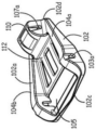
Embodiments of the present invention provide an integrated safety harness connector assembly. The safety harness connector assembly may be used to couple any type of equipment to a safety harness, such as, but not limited to, a self-retracting lifeline (SRL) system. A first embodiment of a safety harness connector assembly 100 is shown in fig. 1. In this embodiment, the safety harness connector assembly 100 includes a D-ring 120, a base dorsal member 102, a device connector system 125. The elements of the safety harness connector assembly 100 will be further described in conjunction with the disassembly view provided in fig. 2. The D-ring 120 is generally C-shaped having a central portion 120a, a first end portion 120b, and a second end portion 120C. Clasp 124 extends across D-ring 120 proximate first end 120b and second end 120 c. Each of the first and second ends 120b and 120c includes a respective D- ring aperture 121b and 121 c. The D- ring holes 121b and 121c are aligned with each other. In the embodiment of fig. 2, first end 120b includes an extending sleeve portion 122 positioned about annular bore 121 b. Sleeve portion 122 includes a bias receiving groove 123. The arms of the biasing member 182 (torsion springs in this exemplary embodiment) are received within the bias receiving slots 123 of the sleeve portion 122 to apply a biasing force to the D-ring 120 to position the D-ring 120 at a desired position relative to the base dorsal member 102.
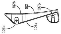
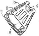
The base backside member 102 is further illustrated in fig. 3A-3E. The base backside member 102 includes a front side surface 102a and a backside surface 102 b. Further, the base backside member 102 includes an upper edge 102c and an opposing lower edge 102 d. Further, the base backside member 102 includes a first side 102e and an opposing second side 102f, as shown in fig. 3B. As shown in the figures, the upper edge 102c is longer in length than the lower edge 102d of the base dorsal member 102. Extending along the length of the first side edge 102e is a first side wall 104 a. The height of the first sidewall 104a varies along its length. In this embodiment, the height of the first sidewall 104a is smaller at the lower edge 102 d. The height of the first wall 104a increases from the lower edge 102d until the height of the first wall 104a reaches a maximum height at a selected location. The selected location of maximum height is proximate to the upper edge 102 c. The height of the first wall 104a then decreases from the point of maximum height to the upper edge 102 c. The base backside member 102 also includes a second sidewall 104b that extends along the length of the second side 102 f. In one embodiment, the second sidewall 104b is a mirror image of the first sidewall 104 a. Positioned between first sidewall 104a and second sidewall 104b is middle plate portion 106. The first side wall 104a, the second side wall 104b, and the mid-plate portion 106 form a tray 112 of elements of the safety harness attachment assembly 100. In this embodiment, the middle plate portion 106 includes a plurality of molding grooves 111. Further, in this embodiment, the middle plate portion 106 extends only a portion of the distance between the lower edge 102d and the upper edge 102c of the substrate backside member 102. The webbing passage 105 is positioned between the middle plate portion 106 and the upper edge 102c of the base back-side member 102. Each of the first and second side walls 104a and 104b includes a respective backside aperture 103a and 103 b. The respective backside apertures 103a and 103b are aligned with each other and positioned at a location of the respective first and second sidewalls 104a and 104b near a maximum height of the respective first and second sidewalls 104a and 104 b. In addition, corresponding backside apertures 103a and 103b are positioned on opposite sides of the webbing passage 105. The base dorsal member 102 also includes a biasing arm retaining slot 113 shown in fig. 3D. The biasing retaining member slots 113 retain the arms of the biasing members 182.
Near the lower edge 102d of the base dorsal member 102 in this embodiment is a load attachment member 110. In one embodiment, the load attachment member 110 is used to attach a load distribution system 296 (shown generally in fig. 5D) of a safety harness 298 to the safety harness attachment assembly 100. The load attachment member 110 includes a pair of aligned spaced apart load attachment holes 107a and 107b and a cavity 115. Clevis pin 190, shown in fig. 2, passes through load attachment holes 107a and 107b to couple the portion of load distribution system 296 of safety harness 298 that is received in the cavity to safety harness attachment assembly 100. In this exemplary embodiment, clevis pin 190 includes a head portion 190a, a pin middle portion 190b, and a tail portion 190 c. In the tail portion 190c is an annular ring 191 designed to receive an open ring 192 to lock the clevis pin 190 to the load attachment member 110.
Referring to fig. 2, D-ring 120 is coupled to base dorsal member 102 by dorsal rivet 180. Specifically, the back-side rivet 180 includes a head portion 180a, a middle shaft portion 180b, and a tail portion 180 c. In this embodiment, the tail portion 180c of the back side rivet 180 has a diameter that is less than the diameter of the middle shaft portion 180 b. The tail portion 180c is connected to a coupling nut 184. The central shaft portion 180b of the back-side rivet 180 is received in the back-side hole 103a, the D-ring hole 121b, the D-ring hole 121c, and the back-side hole 103b to pivotally couple the D-ring 120 to the base back-side member 102. The back side rivets 180 are also used to attach the safety harness connector assembly 100 to the webbing of the safety harness. Referring to fig. 5A-5B, an inset of a harness connector assembly 100 is shown coupled to webbing 195A and 195B as part of a safety harness system. The webbing 195a and 195b will typically extend along the user's back from the user's shoulders to the waistband webbing (not shown). In the embodiment shown, the webbing 195a is crossed with the webbing 195 b. The harness connector assembly 100 is coupled where the webbing 195a and 195b cross. Specifically, as shown in the back view of fig. 5B, the webbing 195a and 195B is threaded around the back rivet 180 in the webbing channel 105 of the base back-side member 102. In one embodiment, the harness connector assembly 100 is mounted to the webbing 195a and 195b by: the crossed webbing 195a and 195b is first placed into the webbing channel 105 of the base dorsal member 102, and the back rivet 180 is then inserted through the back apertures 103a and 103b of the base dorsal member 102. In addition, as shown in fig. 5B, the biasing member 182 is positioned around the backside rivet 180 with one arm received in the biasing retaining member slot 113 of the base backside member 102. As described above, the other arm of biasing member 182 is received within bias receiving slot 123 of sleeve portion 122 to apply a biasing force to D-ring 120 to cause the D-ring to be in a desired position relative to base dorsal member 102.
The device connector system 125 includes a first connector member 130, a swivel connector 140, and a second connector member 150. The first connector member 130 is shown in detail in fig. 4A and 4B. The first connector member 130 includes a first arm 132a and a second arm 132b that extend out of opposite ends of a mounting rod 134. The mounting bar 134 includes a central mounting channel 160 that runs the entire length of the mounting bar 134. Each of the first and second arms 132a and 132b includes a respective rivet channel 133a and 133 b. A respective rivet channel 133a and 133b is located proximate the end of each respective arm 132a and 132 b. In addition, the rivet channels 133a and 133b are aligned. The first connector member 130 is pivotally coupled to the base dorsal member 102 via a dorsal rivet 180 that is received in the aligned rivet channels 133a and 133b of the first connector member 130. Referring back to fig. 2, the swivel connector 140 of the device connector system 125 is further described. The swivel connector 140 is generally C-shaped having a swivel first end 140a, a swivel second end 140C and a curved swivel middle 140 b. The swivel mid-section 140b has a width substantially equal to the width of the mounting bar 134 of the first connector member 130. In addition, the swivel middle portion 140b of the swivel connector 140 is curved to a degree that substantially matches the radius of curvature of the mounting rod 134 of the first connector member 130. In this embodiment, the swivel middle portion 140b of the swivel connector 140 includes slots 143a and 143 b. Further, the swivel middle portion 140b of the swivel connector 140 is positioned around the mounting bar 134 of the first connector member 130. Each of the respective swivel first and second ends 140a, 140c of the swivel connector 140 generally tapers to an endpoint. Further, each of the swivel first and second ends 140a and 140c of the swivel connector 140 includes a pivot connection hole 141a and 141 b. The pivot connection holes 141a and 141b of the swivel connector 140 are aligned with each other.
As further shown in fig. 2, the second connector member 150 is also generally C-shaped. The second connector member 150 has a first end 150a, a second end 150b and a curved middle 150 c. The first end 150a and the second end 150b terminate in a circular configuration. In this embodiment, curved middle portion 150c includes slot 151 c. Each of the first and second end portions 150a and 150b includes respective first and second connector holes 151a and 151 b.
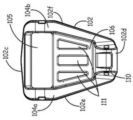
The device connector system 125 is coupled to the base back side member 102 of the safety harness connector assembly 100 via back side rivets 180 received in the rivet channels 133a and 133b of the first connector member 130. In the exemplary embodiment shown in fig. 2, the connector washer 184 is received on the tail portion 180c of the back side rivet 180. The washer 184 is used to provide a surface for the rivet capping operation. The washer 184 also sets the effective length of the rivet by compressing against the rivet shoulder. The swivel mid-section 140b of the swivel connector 140 is received around the mounting bar 134 of the first connector member 130. The connector rivet 186 includes a head 186a, a tip 186c, and a central shaft portion 186b that couples the swivel connector 140 to the first connector member 130. As shown in fig. 2, in this exemplary embodiment, the tip portion 186c of the connector rivet 186 has a diameter that is smaller than the diameter of the middle shaft portion 186 b. The connector rivets 186 are received in the pivot connection holes 141a and 141b of the swivel connector 140, which rivets pivotally couple the swivel connector 140 to the first connector member 130. The swivel connector 140 pivotally rotates about the mounting bar 134 of the first connector member 130. The connector rivet 186 also pivotally couples the second connector member 150 to the swivel connector 140. Specifically, the connector rivets 186 are received in the first and second connector holes 151a and 151b of the second connector member 150 to pivotally couple the connector member 150 to the swivel connector 140. The pivotal connections between each of the first connector member 130 and the base dorsal member 102, the first connector member 130 and the swivel connector 140, and the swivel connector 140 and the second connector member 150 allow the device connector 125 to be positioned in different configurations for attaching different types of devices. In fig. 1, the device connector system 125 is shown positioned in the tray 112 of the base dorsal member 102. Further, fig. 5C shows the second connecting member 150 pivoted with respect to the swivel connector 140. Additionally, in the exemplary embodiment shown in fig. 1, the pivot axis 155 of the second connector member 150 about the connector rivet 186 is in a substantially perpendicular orientation relative to the pivot axis 157 of the swivel connector 140 about the mounting bar 134 and the pivot axis 159 of the first connector member 130 about the back side rivet 180. Additionally, fig. 5D illustrates the safety harness connector assembly 100 coupled to a safety harness 298 worn by a user 295. Specifically, the safety harness connector assembly 100 is coupled to the webbing 195a and 195b of the safety harness 298. Also shown in fig. 5D is a load distribution system 296 coupled to the load attachment member 110 of the safety harness connector member 130. The load distribution system 297 transfers the load on the safety harness connector assembly 100 to the hip plate 298 coupled to the hip pad 293 of the safety harness 298 through the adjustable load strip 297. As further shown, the hip webbing 299 of the safety harness 298 is threaded through the webbing retaining members 291a and 291b in the hip plate 298.
Referring to fig. 6A, an illustration of device connector system 125 is shown positioned in a configuration to receive device connector 200. In this example, the connector 200 is a self-retracting lifeline (SRL) connector. Fig. 6A also shows an SRL system 201 that includes an SRL202, a lifeline 204, an energy absorption system 206, and a support structure connector 208. Connection ring 203 is coupled to the housing of SRL 202. Fig. 6B shows the SRL system 201 coupled to the safety harness connector assembly 100. In this example, the connection ring 203 receives a mounting rod portion 205 of the SRL connector 200. A mounting rod portion 205 is also received within the second connecting channel 170 of the second connecting member 150 to pivotally couple the SRL system 201 to the safety harness webbing 195a and 195 b. Fig. 6B also shows that in this configuration, the connection ring 203 is received in the slot 151c of the second connection member 150.
Fig. 7A is an illustration of the device connector system 125 positioned in a configuration to receive a different SRL connector 210. In this example, the SRL connector 210 is a hook and loop. Fig. 6B shows the SRL system 201 coupled to the safety harness connector assembly 100 by a hook and loop connector 210. In this example, the attachment loop 203 is received a portion of the hook-and-loop connector 210, while another portion of the hook-and-loop connector 210 is received within the second connection channel 170 of the second connection member 150 to pivotally couple the SRL system 201 to the webbing 195a and 195b of the safety harness.
Referring to fig. 8A, an illustration of the device connector system 125 is shown positioned in a configuration to receive the connector 212. In this example, the connector 212 is an SRL connector designed to attach the dual SRL system 214 to the safety harness attachment assembly 100. Fig. 8A shows a dual SRL system 214 that includes a pair of SRLs 216a and 216b, lifelines 218A and 218b, and support structure connectors 220a and 220 b. Fig. 8B illustrates a dual SRL system 214 coupled to the safety harness connector assembly 100. In this example, the mounting rod portion 211 of the SRL connector 212 (shown in fig. 8A) is received within the first connector channel 160 of the first connector member 130 to pivotally couple the dual SRL system 214 to the webbing 195a and 195b of the safety harness. Thus, as shown and described, the device connector system 125 of the safety harness connector assembly 100 may be positioned in different configurations and have different connection points such that the device connector system 125 may couple different types of devices and connectors to the webbing 195a and 195b of the safety harness.
Another embodiment of a safety harness connector assembly 300 is shown in fig. 9A-14. Fig. 9A and 9B illustrate the device connector system 325 of the safety harness connection assembly 300 in different configurations to couple different devices to the webbing 330a and 330B of a safety harness (not shown). Fig. 10 shows a disassembled view of the safety harness attachment assembly 300. The safety harness attachment assembly 300 includes a D-ring 302. The D-ring 302 is generally C-shaped having a central portion 302a, a first end portion 302b, and a second end portion 302C. Clasp 322 extends across D-ring 302 proximate first end 302b and second end 302 c. Each of the first and second ends 302b and 302c includes a respective D- ring aperture 321a and 321 b. The D- ring holes 321a and 321b are aligned with each other.
The safety harness connector assembly 300 also includes a device connector system 325. Device connector system 325 includes a base member 310, a first connector member 306a, a second connector member 306b, a first link 304a, a second link 304b, a back side rivet 320, and a connecting rivet 332. The base member 310 includes a mid-barrel portion 312. Extending on opposite ends of the middle barrel portion 312 are respective first and second pipe portions 314a and 314 b. The first and second pipe portions 314a and 314b have a diameter smaller than the diameter of the mid-barrel portion 312. A central connector rivet hole 315 extends through the first tube portion 314a, the middle barrel portion 312, and the second tube portion 314 b. The base member further includes first and second connecting arms 316a, 316b that extend in spaced parallel relation from the surface of the central barrel portion 312. The first and second connecting arms 316a and 316b terminate in a rounded edge and each connecting arm 316a and 316b includes a respective device connecting channel 317a and 317b aligned with each other. In an exemplary embodiment, the first connector member 306a is a mirror image of the second connector member 306 b. The first and second connector members 306a, 306b extend a selected length terminating in a rounded edge. First connector member 306a includes a first bore 307a configured to receive first tube portion 314a of base member 310. Similarly, second connector member 306b includes a first bore 311a configured to receive second tube portion 314b of base member 310. First connector member 306a further includes a connection aperture 307b, and second connector member 306b further includes a connection aperture 311 b. In an exemplary embodiment, first connector member 306a and second connector member 306b include respective apertures 309 and 313 for weight reduction. The device connector system 325 also includes a first link 304a and a second link 304 b. The first link 304a is a mirror image of the second link 304 b. Both the first link 304a and the second link 304b extend a selected length terminating in a rounded edge. The first link 304a has a first link first hole 305a near a first end of the first link 304a, and a first link second hole 305b near a second end of the first link 304 a. The second link 304b has a second link first aperture 303a near a first end of the second link 304b and a second link second aperture 303b near a second end of the second link 304 b.
The back rivet 320 has a central shaft 320c and ends terminating in first and second heads 320a and 320b, which are received in the first link first hole 305a of the first link 304a, the D- ring holes 321a and 321b of the D-ring 302, and the second link first hole 303a of the second link 304b to pivotally couple the first and second links 304a and 304b to the D-ring 302. A connecting rivet 332 having a central shaft portion 332c and ends terminating in first and second head portions 332a and 332b is received in first link second hole 305b of first link 304a, first hole 307a of first connector member 306a, central connector rivet hole 315 of base member 310, first hole 311a of second connector member 306b, and second link second hole 303b of second link 304b to pivotally couple the remainder of device connector system 325 to D-ring 302. The pivotal connection in this configuration enables different positioning of the device connector system 325. For example, fig. 9A illustrates one possible configuration of a device connector system 325 in which the connection aperture 307b of the first connector member 306a is aligned with the connection aperture 311b of the second connector member 306b, while the device connection channels 317a and 317b of the respective first and second connection arms 316a and 316b are aligned with each other. In the configuration of FIG. 9B, all of the holes 307B, 311B are aligned with channels 317a and 317B.
Fig. 11 shows that the webbing 330a and 330b is positioned between the central shaft portion 320c of the back-side rivet 320 and the D-ring 302 at their intersection, and the device connector system 325 is used to couple the webbing 330a and 330b of the safety harness to the safety harness connection assembly 300. Fig. 12 shows a shackle 340 coupled to a device connector system 325 by receiving the shackle in the device connection channels 317a and 317b of the respective first and second connection arms 316a and 316 b. Any type of device may then be coupled to the shackle 340 in sequence. Fig. 13 shows an SRL system 361 that is coupled to the webs 330a and 330b by an equipment connector system 325. The SRL connector 350 is received in the device connection channels 317a and 317b of the respective first and second connection arms 316a and 316b of the device connector system 325. In this example, SRL system 361 includes SRL360, lifeline 362, energy absorber 364, and support structure connector 366. Referring to fig. 14, an illustration of the device connector system 325 is shown coupling a dual SRL system 381 to the webbing 330a and 330b of the safety harness. In this exemplary embodiment, the SRL connectors are received in all of the aligned apertures 307b, 311b and channels 317a and 317b in the respective first and second connector members 306a, 306b and first and second connecting arms 316a, 316 b. The SRL system 381 includes a pair of SRLs 380a and 380b and their corresponding lifelines 382a and 382b and support structure connectors 384a and 384 b.
Another embodiment of a safety harness attachment assembly 400 is shown in fig. 15A-17. This embodiment includes a D-ring 402 and a device connector system 425. As shown in the exploded view of fig. 16, D-ring 402 is generally C-shaped having a central portion 402a, a first end portion 402b, and a second end portion 402C. Clasp 422 extends across D-ring 402 proximate first end 402b and second end 402 c. Each of the first and second ends 402b and 402c includes a respective D- ring hole 421a and 421 b. The D- ring holes 421a and 421b are aligned with each other.
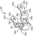
The device connector system 425 of the safety harness connection assembly 400 includes a base member 410, a door member 430, and a lock member 450. The base member 410 includes a base plate 412. The stopper plate 414 extends at one end of the base plate 412. The stop plate 414 is shaped to bend over some portion of the base plate 412. A pair of base arms 416a and 416b extend adjacent opposite ends of the base 412. Each base arm 416a and 416b extends in a generally perpendicular manner relative to the base plate 412. Base arms 416a and 416b are spaced apart in a parallel manner relative to each other by a distance approximately the width of substrate 412. First base arm 416a includes a first base arm first bore 411a and a spaced first arm second bore 413 a. Second base arm 416b includes a second base arm first bore 411b and a spaced second arm second bore 413 b. The first base arm first hole 411a is aligned with the second base arm first hole 411b and the first base arm second hole 413a is aligned with the second base arm second hole 413 b.
The door 430 includes a door base 432. Extending from opposite sides of the door substrate 432 near the first end of the door substrate 432 are parallel first and second door arms 434a and 434 b. The end portions of door arms 434a and 434b terminate in respective stop edges 435a and 435 b. Further, extending from opposite sides of the door substrate 432 near the second end of the door substrate 432 are parallel first and second coupling ears 431a and 431 b. Although only tab 431a is shown in FIG. 16, the opposing tab 431b (shown in FIG. 15C) is a mirror image of tab 431 b. Each of the coupling lugs 431a and 431b includes a pivot coupling hole 433. The first and second door arms 434a and 434b and the coupling lug 431 extend in a perpendicular manner with respect to the door substrate 432 in substantially the same direction. The lock member 450 includes a lock plate 452. The locking plate 452 includes a first edge 446a and an opposing second edge 446 b. The locking plate 452 further includes a third edge 448a and an opposing fourth edge 448 b. The lock plate 452 includes a pair of parallel spaced apart first and second lock stop arms 454a, 454b that extend generally from the first edge 446a of the lock plate 452. The lock plate 452 also includes a first coupling lug 456. The first attachment tab 456 extends generally perpendicularly from the lock plate 452 from a fourth edge 448b adjacent the second edge 446 b. The first coupling ears 456 include first lock plate apertures 457. The second attachment ear 458 extends generally perpendicularly from the lock plate 452 from a third edge 448a proximate the second edge 446 b. The second attachment ear 458 has second lock plate apertures 459 that align with the first lock plate apertures 457 of the first attachment ear 456. The third ear 451 extends generally perpendicularly from the second attachment ear 458 in the following manner: the third ear 451 is positioned above and parallel to the lock plate 452. The third ear includes indicia indicating the direction to move the locking plate 452 to unlock the door 430. In this exemplary embodiment, the lock plate 452 includes a lock slot 453 that extends a selected distance between the first and second attachment ears 456, 458.
The device connector system 425 of the safety harness connector assembly 400 further includes a lock biasing member 408, a door biasing member 406, a back side rivet 470, and a connection rivet 460. The back side rivet 470 includes a central portion 470a and end portions that terminate in head portions 470b and 470 c. The attachment rivet 460 includes a middle portion 460a, a head portion 460b, and an attachment end 460 c. The connecting end 460c has a diameter smaller than the diameter of the middle portion 460 a. The coupling nut 461 engages the coupling end 460c of the coupling rivet 460. The base arms 416a and 416b of the base member 410 of the device connector system 425 are positioned between the first end 402b and the second end 402c of the D-ring such that the D- ring holes 421a and 421b are aligned with the first base arm first hole 411a and the second base arm first hole 411b of the base member 410. Backside connection rivets 470 are received in the D- ring holes 421a and 421b and the first and second base arm first holes 411a and 411b to pivotally couple the base member 410 of the device connector system 425 to the D-ring 402. The lock member 450 and the door member 430 are positioned between the base arms 416a and 416b of the base member 410 such that the first base arm second aperture 413b and the second arm second aperture 413b of the base member 410 are aligned with: the second and first lock plate apertures 459 and 457 of the lock member 450 and the door opening 433 of the door 430. Connector rivets 470 are received in the first and second base arm second holes 413a and 413b of the base member 410 and the second and first lock plate holes 459 and 457 of the lock member 450 and the door hole 433 of the door 430 to pivotally couple the door member 430 to the base member 410. The door arms 434a and 434b of the door member 430 are also aligned with the door channels 417a and 417b in the base member 410.
The door biasing member 406 receives the middle of the connector rivet 470 and is positioned between the attachment ears 431a and 431b of the door 430 (as shown in fig. 15C). The door biasing member 406 is positioned against the biased door 430 of the stop plate 414 of the base member 410. The lock biasing member 408 also receives the middle portion 460a of the connector rivet 460. The lock biasing member 408 is positioned between the second base arm 416b of the base member 410 and the first coupling ear 456 of the lock member 450. The lock biasing member 408 is positioned to bias the lock member 450 to the following positions: the door 430 is locked in position in a stationary configuration relative to the base member 410. The lock member 450 biased in the locked position is shown in fig. 15A. As shown in fig. 15A, the first lock stop arm 454a of the lock member 450 engages the stop edge 435A of the door arm 434a to prevent the door arm 434a from traveling into the door channel 417a of the plate 412 of the base member 410. In the locked configuration, the connector may be retained within the channel 411 (shown in fig. 15D) of the safety harness connector assembly 400. The door 430 is opened by applying a force to the lock member 450 against the biasing force of the lock biasing member 408. This operation moves the first and second latch arms 454a and 454b of the latch member 450 away from the door channels 417a and 417b of the base member 410. The door 430 can then be pressed to check the door biasing member 406 because the door arms 434a and 434b can now pass into the door channels 417a and 417b of the base member 410. When the door is open, the device connector may be placed into the channel 411 of the safety harness connector assembly 400. Once the force on the door 430 is removed, the safety harness connector assembly 400 will again become automatically locked due to the biasing force of the door biasing member 406 and the lock biasing member 408. Fig. 17 shows the safety harness connector assembly 400 coupled to the SRL system 490 by the SRL connector 492. A portion of the SRL connector 492 is received within the channel 411 of the device connector system 425 of the safety harness connector assembly 400. In this exemplary embodiment, the SRL system 490 includes a pair of SRLs 494a and 494b, a pair of lifelines 496a and 496b, and a pair of support structure connectors 498a and 498 b.
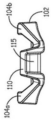
Another embodiment of a safety harness attachment assembly 500 is shown in fig. 18A-20. This embodiment includes a D-ring 502 and a device connector system 525. As shown in the exploded view of fig. 20, D-ring 502 is generally C-shaped having a middle portion 502a, a first end portion 502b, and a second end portion 502C. Clasp 522 extends across D-ring 502 proximate first end 502b and second end 502 c. Each of the first end 502b and the second end 502c includes a respective D- ring hole 521a and 521 b. D- ring holes 521a and 521b are aligned with each other.
The safety harness connector assembly 500 also includes a device connector system 525. Device connector system 525 includes a base member 510 and a connector member 530. The base member 510 includes a tubular portion 512 having a central base passage 515. Extending from the surface of the tubular portion 512 are a first base arm 514a and a second base arm 514b, which in this embodiment are mirror images of each other. Further, in this embodiment, the first base arm 514a and the second base arm 514b extend from the surface of the tubular portion 512 in parallel to each other. The first base arm 514a includes a first base arm hole 513a and the second base arm 514b includes a second base arm hole 513 b. The first base arm hole 513a is aligned with the second base arm hole 513 b. The connector member 530 includes a first link 532 and a second link 534, the first link 532 being coupled to the second link 534 by a connector bar portion 536 such that the first link 530 and the second link 534 are positioned parallel to each other but perpendicular with respect to the connector bar portion 536. The first link 532 includes a first link first hole 531a and a first link second hole 533 a. The second link 532 includes a second link first hole 531b and a second link second hole 533 b. The first link first hole 531a of the first link 532 is aligned with the second link first hole 531b of the second link 534. In addition, the first link second hole 533a of the first link 532 is aligned with the second link second hole 533b of the second link 534. In addition, the connector bar portion 536 is coupled to the first link 532 proximate the first link second aperture 533a and to the second link 534 proximate the second link second aperture 533 b.
Fig. 18A shows device connector system 525 in a first configuration. In this configuration, the first link second aperture 533a, the first base arm aperture 513a, the second base arm aperture 531b, and the second link second aperture 533b are all aligned to receive a connector for coupling the device to the webbing 580a and 580 b. In fig. 18B, the connector member 530 is pivoted about the connector rivet 570 such that the first link second aperture 533a and the second link second aperture 533B are no longer aligned with the first base arm aperture 513a and the second base arm aperture 513B. This configuration enables the use of different types of connectors. Fig. 19 shows how the webbing 580a and 580b is threaded around the central shaft portion 560a of the back-side rivet 560 to couple the safety harness connector assembly 500 to the webbing 580a and 580 b.
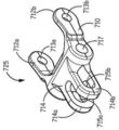
Referring to fig. 21-26C, another safety harness attachment assembly 600 embodiment is shown. In this embodiment, the safety harness connection assembly 600 includes a D-ring 602 and a device connector system 625. Referring to fig. 23, D-ring 602 is generally C-shaped having a central portion 602a, a first end portion 602b, and a second end portion 602C. Clasp 622 extends across D-ring 602 proximate first end 602b and second end 602 c. Each of the first end 602b and the second end 602c includes a respective D- ring hole 621a and 621 b. The D- ring holes 621a and 621b are aligned with each other.
The device connector system 625 includes a base member 610, as best shown in fig. 23. The base member 610 has a first edge 604 and an opposing second edge 605. The base member 610 also has a third edge 606 and an opposing fourth edge 607. A drilled passage 617 extends through the base member 610 from the third edge 606 to the fourth edge 607. The drilled passage 617 is positioned near the first edge 604 of the base member 610. Spaced apart first and second arms 612a, 612b extend from the second edge 605 of the base member 610. The first arm 612a includes a first arm hole 613a, and the second arm 612b includes a second arm hole 613 b. The first arm hole 613a and the second arm hole 613b are aligned with each other. A generally U-shaped connecting member 614 extends in a perpendicular manner from the surface of the base member 610. The opening of the U-shape faces the first edge 604 of the base member 610. The connecting member 614 includes a first wall 614a and a second wall 614b positioned substantially parallel to each other. The first wall 614a includes first wall apertures 615a and the second wall 614b includes second wall apertures 615 b. The first wall hole 615a and the second wall hole 615b are aligned. The device connector system also includes a back side rivet 630. Back-side rivet 630 includes a middle shaft portion 630a that terminates in head ends 630b and 630 c. Arms 612a and 612b of base member 610 are positioned between ends 602b and 602c of D-ring 602. The middle shaft portion 630a of the back side rivet 630 received in the D-ring hole 621a, the first arm hole 613a, the second arm hole 613b, and the D-ring hole 621b pivotally couples the device connector system 625 to the D-ring 602.
Fig. 21 illustrates a safety harness connection assembly 600 coupled to webbing 640a and 640b of a safety harness (not shown). Fig. 22 shows a back view of the safety harness attachment assembly 600 coupled to the webbing 640a and 640 b. As shown, webbing 640a and 640b is threaded around the central shaft portion 630a of the back-side rivet 630 to couple the safety harness attachment assembly 600 to the webbing 640a and 640 b. Fig. 24 illustrates a safety harness connection assembly 600 coupled to an SRL system 680 by an SRL connector 650 received in the bored passage 617 of the base member 610. In this example, the SRL system 680 includes a pair of SRLs 660a and 660b, a pair of safety cables 662a and 662b, and a pair of support structure connectors 664a and 664 b. Fig. 25 shows a safety harness connection assembly 600 that is coupled to another SRL system 682 by a shackle 685 received in first and second wall apertures 615a and 615b of the base member 610. In this embodiment, the SRL system includes an SRL686, a lifeline 688, an energy absorber 690, and a support structure connector 692.
Fig. 26A shows a device connector system 625 as described above. Fig. 26B illustrates an alternative embodiment of a device connector system 625 that may be used in the safety harness connection assembly 600 described above. The device connector system 725 in fig. 26B includes a base member 710. The base member 710 includes arms 712a and 712b and aligned arm channels 713a and 713b and a bore channel 717, similar to that described in connection with the device connector system 625. The device connector system 725 differs in that: the connecting member 714 extends from the edge of the base member 710 in a direction opposite the arms 712a and 712 b. Connecting member 714 includes walls 714a and 714b that include aligned wall channels 715a and 715 b. Another exemplary device connector system 825 is shown in fig. 26C. In this exemplary embodiment, the base member 810 is generally U-shaped, including a first arm 812a, a second arm 812b, and a bridge 808. The bridge 808 is coupled between the ends of the first arm 812a and the second arm 812 b. The first arm 812a includes a first arm passage 813a that is aligned with a second arm passage in the second arm 812 b. The arms 812a and 812b include respective aligned drilled passages 817a and 817 b. Aligned drilled passages 817a and 817b are located adjacent to the bridge 808. Extending from the center of the bridge 808 is a connecting portion 814. The connecting portion 814 is also generally U-shaped having a first wall 814a and an opposing second wall 814 b. The first wall 814a includes a first wall channel 815a and the second wall 814b includes a second wall channel 815b that is aligned with the first wall channel 815 a. Thus, different interchangeable device connector systems 625, 725, 825 may be used with the safety harness attachment assembly 600.
Referring to fig. 27-30, another embodiment of a safety harness attachment assembly 900 is shown. This embodiment includes a D-ring 902 and a device connector system 925. As shown in the exploded view of fig. 29, D-ring 902 is generally C-shaped having a middle portion 902a, a first end portion 902b, and a second end portion 902C. Clasp 922 extends across D-ring 902 proximate first end 902b and second end 902 c. Each of the first end 902b and the second end 902c includes a respective D- ring hole 921a and 921 b. The D- ring holes 921a and 921b are aligned with each other.
The safety harness connector assembly 900 also includes a device connector system 925, as best shown in fig. 29. Device connector system 925 comprises base member 910 and connector member 914. The base member 910 includes a base plate 911. First and second arms 912a and 912b extend perpendicularly from opposite ends of the base plate 911. The first arm 912a includes a first arm hole 913a, and the second arm 912b includes a second arm hole 913 b. The first arm hole 913a is aligned with the second arm hole 913 b. In one embodiment, the connector member 914 is comprised of a webbing 918 that is folded over onto itself to form a backside hole 915 at one end and a device attachment hole 917 passage at the other end. Specifically, the webbing 918 includes a first portion 918a onto which a second portion 918b is folded. In addition, a third portion 918c of the webbing (which is shorter than the first and second portions 918a, 918 b) is folded over and positioned between the first and second portions 918a, 918 b. The first portion 918a, the second portion 918b, and the third portion 918c are coupled together at a portion where all of the webbing overlaps. In one embodiment, stitching is used to couple portions 918a, 918b, and 918c together, although other methods may be used, such as, but not limited to, riveting. The device connector system 925 also includes a backside rivet 930. Back side rivet 930 includes a middle shank portion 930a that terminates in head ends 930b and 930 c. The base member 910 is positioned between the first end 902b and the second end 902c of the D-ring such that the first arm hole 913a and the second arm hole 913b of the base plate 910 are aligned with the D- ring holes 921a and 921b of the D-ring 902. Further, a portion of the connector member 914 is positioned between the first arm 912a and the second arm 912b of the substrate member 910 such that the backside hole 915 of the connector member 914 is aligned with the first arm hole 913a and the second arm hole 913b of the base member 910. The middle shaft portion 930a of the back side rivet 930 is received in the D-ring hole 921a, the first arm hole 913a, the back side hole 915, the second arm hole 913b, and the D-ring hole 921b to pivotally couple the device connector system 925 to the D-ring 902.
Fig. 27 shows the safety harness connection assembly 600 coupled to the webbing 942a and 942b of the safety harness (not shown). Fig. 28 shows a back view of the safety harness attachment assembly 900 coupled to the webbing 942a and 942 b. As shown, the webbing 942a and 942b is threaded between the base plate 911 of the base member 910 and the back side rivet 930 (received in the back side aperture 915 of the connector member 914) to couple the webbing 942a and 942b to the safety harness connection assembly 900. Referring to fig. 30, a SRL system 980 coupled to the safety harness attachment assembly 900 is shown. As shown, a portion of the SRL connector 950 is received in the equipment connection channel 917 of the connector member to couple the SRL system 980 to the safety harness connection assembly 900. The exemplary SRL system 980 includes a pair of SRLs 982a and 982b, a pair of lifelines 984a and 984b, and a pair of support structure connectors 986a and 986 b.
Although specific embodiments have been illustrated and described herein, it will be appreciated by those of ordinary skill in the art that any arrangement which is calculated to achieve the same purpose may be substituted for the specific embodiments shown. This application is intended to cover any adaptations or variations of the present invention. Therefore, it is manifestly intended that this invention be limited only by the claims and the equivalents thereof.
Claims (18)
1. A safety harness connector assembly comprising:
a D-ring having a C-shape, the D-ring including a first end portion having a first D-ring aperture, a second end portion having a second D-ring aperture, and a middle portion extending between the first end portion and the second end portion, the first D-ring aperture aligned with the second D-ring aperture;
a shaft engaged with the first D-ring and the second D-ring, the shaft including a longitudinal shaft centerline;
a device connector, the device connector comprising:
a base member; and
a first connector member pivotally coupled directly to the base member via the shaft to provide pivotal movement of the first connector member relative to the base member about the shaft axis,
wherein the D-ring is directly pivotally coupled to the first connector member via the shaft to provide pivotal movement of the D-ring about the shaft axis relative to both the base member and the first connector member.
2. The safety harness connector assembly of claim 1, wherein the base member includes at least one shaft connection hole engaged with the shaft to directly pivotally couple the base member to the D-ring, and the first connector member includes at least one device connection hole to couple one or more safety devices to the safety harness connector assembly.
3. The safety harness connector assembly of claim 2, wherein the base member further comprises at least one base device connection aperture constructed and arranged to couple one or more safety devices to the safety harness connector assembly.
4. The safety harness connector assembly of claim 3, wherein the at least one base device connection aperture and the at least one device connection aperture are selectively aligned in a selected configuration of the device connector.
5. The safety harness connector assembly of claim 1, wherein the device connector further comprises:
a swivel connector pivotally coupled to the first connector member; and
a second connector member pivotally coupled directly to the swivel connector, the second connector member having a second device connecting passage.
6. The safety harness connector assembly of claim 5, wherein the first connector member pivots about the axis and the second connector member pivots about a second axis, the second axis being perpendicular to the axis.
7. The safety harness connector assembly of claim 1, wherein the base member comprises:
a first side wall;
a second side wall; and
a middle plate portion coupled between the first and second side walls to form a tray to hold the device connector.
8. The safety harness connector assembly of claim 7, wherein the base member has a webbing passage constructed and arranged to allow a webbing of a safety harness to be threaded around the shaft to couple the safety harness connector assembly to the webbing of the safety harness.
9. The safety harness connector assembly of claim 1, wherein the base member comprises:
a load attachment member constructed and arranged to couple a load member of a safety harness to the base member of the safety harness connector assembly.
10. The safety harness connector assembly of claim 1, wherein the first connector member further comprises:
a first arm having a first channel;
a second arm having a second channel aligned with the first channel of the first arm, the first and second channels receiving the shaft; and
a mounting rod, the first arm extending from a first end of the mounting rod and the second arm extending from a second end of the mounting rod.
11. The safety harness connector assembly of claim 5, wherein the second connector member further comprises:
a first end portion;
a second end pivotally coupled to the swivel connector; and
a middle portion of a C-shape forming the second device connection channel, the middle portion of the second connector member further having a slot.
12. The safety harness connector assembly of claim 1, in combination with a safety harness to form a safety harness system.
13. A safety harness connector assembly comprising:
a D-ring having a C-shape, the D-ring comprising a first end portion, a second end portion, and a middle portion extending between the first end portion and the second end portion, the first end portion having a first D-ring aperture and the second end portion having a second D-ring aperture, the first D-ring aperture aligned with the second D-ring aperture;
a shaft received in the first and second D-ring holes; and
a device connector through which the safety harness connector assembly is coupled to a device, the device connector comprising:
a base member directly pivotally coupled to the D-ring via the shaft;
a first connector member directly pivotally coupled to the base member, the first connector member being pivotable in a first direction relative to the base member, the first connector member having a first device connection passage;
a swivel connector pivotally coupled directly to the first connector member; and
a second connector member directly pivotally coupled to the swivel connector, the second connector member being pivotable relative to the base member in a second direction, the second direction being different from the first direction.
14. The safety harness connector assembly of claim 13, wherein the first connector member pivots about a first axis and the second connector member pivots about a second axis, the second axis being perpendicular to the first axis.
15. The safety harness connector assembly of claim 13, wherein the base member further comprises:
a first side wall;
a second side wall; and
a mid-plate portion coupled between the first and second side walls to form a tray to hold the device connector, at least the first, second, and mid-plate portions forming a webbing passage constructed and arranged to allow webbing of a safety harness to be threaded around the shaft to couple the safety harness connector assembly to the webbing of the safety harness.
16. A safety harness connector assembly comprising a device connector through which the safety harness connector assembly is coupled to a device, the device connector comprising:
a base member directly pivotally coupled to at least one webbing of a safety harness;
a first connector member directly pivotally coupled to the base member, the first connector member being pivotable in a first direction relative to the base member, the first connector member having at least one first device connecting channel;
a swivel connector pivotally coupled directly to the first connector member; and
a second connector member directly pivotally coupled to the swivel connector, the second connector member being pivotable relative to the base member in a second direction, the second direction being different from the first direction.
17. The safety harness connector assembly of claim 16, wherein the first connector member pivots about a first axis and the second connector member pivots about a second axis, the second axis being perpendicular to the first axis.
18. The safety harness connector assembly of claim 16, further comprising:
a D-ring having a C-shape, the D-ring comprising a first end portion, a second end portion, and a middle portion extending between the first end portion and the second end portion, the first end portion having a first D-ring aperture and the second end portion having a second D-ring aperture, the first D-ring aperture aligned with the second D-ring aperture;
a shaft received in the first and second D-ring holes; and
the base member including at least one shaft connection hole that receives the shaft to pivotally couple the base member to the D-ring.
Applications Claiming Priority (5)
| Application Number | Priority Date | Filing Date | Title |
|---|---|---|---|
| US201562173823P | 2015-06-10 | 2015-06-10 | |
| US62/173,823 | 2015-06-10 | ||
| US14/800,199 US10232199B2 (en) | 2015-06-10 | 2015-07-15 | Integral safety harness connector assembly |
| US14/800,199 | 2015-07-15 | ||
| PCT/US2016/036216 WO2016200809A1 (en) | 2015-06-10 | 2016-06-07 | Integral safety harness connector assembly |
Publications (2)
| Publication Number | Publication Date |
|---|---|
| CN107787241A CN107787241A (en) | 2018-03-09 |
| CN107787241B true CN107787241B (en) | 2021-02-05 |
Family
ID=56297091
Family Applications (1)
| Application Number | Title | Priority Date | Filing Date |
|---|---|---|---|
| CN201680034100.3A Active CN107787241B (en) | 2015-06-10 | 2016-06-07 | Integrated safety harness connector assembly |
Country Status (10)
| Country | Link |
|---|---|
| US (1) | US10232199B2 (en) |
| EP (1) | EP3307401A1 (en) |
| JP (1) | JP6832295B2 (en) |
| KR (1) | KR20180016544A (en) |
| CN (1) | CN107787241B (en) |
| AU (1) | AU2016274512B2 (en) |
| BR (1) | BR112017026661B1 (en) |
| CA (1) | CA2988958A1 (en) |
| RU (1) | RU2687813C1 (en) |
| WO (1) | WO2016200809A1 (en) |
Families Citing this family (18)
| Publication number | Priority date | Publication date | Assignee | Title |
|---|---|---|---|---|
| EP2982417B1 (en) * | 2014-08-04 | 2018-07-04 | Honeywell International Inc. | Deformable energy absorber with deformation indicator |
| FR3049869B1 (en) * | 2016-04-08 | 2018-06-22 | Zedel | HARNESS |
| FR3049870A1 (en) * | 2016-04-08 | 2017-10-13 | Zedel | HARNESS |
| GB2557308B (en) * | 2016-12-06 | 2020-06-24 | Treemagineers Ltd | Harnesses |
| WO2019012468A1 (en) * | 2017-07-13 | 2019-01-17 | 3M Innovative Properties Company | Fall arresting device connector |
| US10343001B2 (en) * | 2017-09-07 | 2019-07-09 | Honeywell International Inc. | Fall protection lanyard capable of direct connection to harness webbing |
| BR112020005471A2 (en) * | 2017-09-22 | 2020-09-29 | 3M Innovative Properties Company | parachute device connector |
| US11369816B2 (en) * | 2018-04-26 | 2022-06-28 | Pure Safety Group, Inc. | Positionable connector assembly |
| WO2020065457A1 (en) * | 2018-09-27 | 2020-04-02 | 3M Innovative Properties Company | Fall-protecton assembly comprising a soft, endless connector |
| US11524188B2 (en) | 2018-10-09 | 2022-12-13 | Checkmate Lifting & Safety Ltd | Tensioning device |
| TWM574499U (en) * | 2018-11-21 | 2019-02-21 | 張恬馨 | Guiding type fall protection back-carrying kit |
| US20220080233A1 (en) * | 2019-01-16 | 2022-03-17 | 3M Innovative Properties Company | Safety Harness with Removable Rigid Dorsal Force-Transfer Member |
| USD932109S1 (en) | 2019-01-22 | 2021-09-28 | Checkmate Lifting & Safety Ltd | Coupler for a fall protection device |
| GB2580674B (en) * | 2019-01-22 | 2022-12-07 | Checkmate Lifting & Safety Ltd | Coupler for a fall protection device |
| JP2023502462A (en) * | 2019-11-21 | 2023-01-24 | スリーエム イノベイティブ プロパティズ カンパニー | Safety harness with self-locking back brace |
| WO2021246877A1 (en) * | 2020-06-02 | 2021-12-09 | Holmes Solutions Limited Partnership | Movement control system and method of use |
| US20220096881A1 (en) * | 2020-09-25 | 2022-03-31 | Werner Co. | Harness adjustment device |
| CN115671597A (en) * | 2021-07-23 | 2023-02-03 | 霍尼韦尔国际公司 | Integrated personal protective equipment connector element for use with wearable harness |
Citations (7)
| Publication number | Priority date | Publication date | Assignee | Title |
|---|---|---|---|---|
| US1642911A (en) * | 1926-01-08 | 1927-09-20 | Carl G Thurnau | Workman's saddle belt |
| GB2314756B (en) * | 1996-06-28 | 1999-12-15 | Graham David Roberts | Safety strap for a cable or the like |
| JP2008148803A (en) * | 2006-12-15 | 2008-07-03 | Prop:Kk | Harness type safety belt |
| CN102316938A (en) * | 2009-02-26 | 2012-01-11 | C.A.M.P.股份公司 | Element for the attachment of parts of a safety harness |
| WO2012063064A2 (en) * | 2010-11-12 | 2012-05-18 | Latchways Plc | Safety line connector |
| CN102811774A (en) * | 2010-02-25 | 2012-12-05 | Db工业股份有限公司 | Jet bridge fall protection assembly |
| US20150107059A1 (en) * | 2011-10-28 | 2015-04-23 | D B Industries, Llc | Connector |
Family Cites Families (54)
| Publication number | Priority date | Publication date | Assignee | Title |
|---|---|---|---|---|
| US4005904A (en) * | 1975-06-24 | 1977-02-01 | Sigmatex, A.G. | Run through bracket |
| JP2564594Y2 (en) * | 1992-05-08 | 1998-03-09 | 藤井電工株式会社 | Shock absorber for fall prevention safety belt |
| US5329884A (en) | 1992-06-04 | 1994-07-19 | Michael Bell | Harness with adjustable positioning pad and tool belt |
| US5531292A (en) | 1994-08-19 | 1996-07-02 | Bell; Michael | Harness with adjustable means for supporting a tool belt |
| US6405685B1 (en) | 1996-09-24 | 2002-06-18 | Dalloz Fall Protection Investment, Inc. | Method of fabricating a safety harness |
| US5957091A (en) | 1997-11-19 | 1999-09-28 | Rose Manufacturing Company | Full body harness for fall arrest |
| US6253874B1 (en) | 1998-05-22 | 2001-07-03 | D B Industries, Inc. | Methods and apparatus for interconnecting harness straps |
| US6073724A (en) * | 1998-10-23 | 2000-06-13 | D B Industries, Inc. | Connector for a personal safety device |
| AU3485600A (en) | 1999-02-09 | 2000-08-29 | Soll Usa, Llc | Suspension harness |
| DE10011753C2 (en) * | 2000-03-13 | 2003-10-09 | Hubert Kowalewski | Climbing device for ascending and descending processes |
| US6691824B2 (en) | 2000-10-13 | 2004-02-17 | Ultra-Safe, Inc. | Comfortable safety harness |
| US6739427B2 (en) | 2001-02-02 | 2004-05-25 | Bacou-Dalloz Fall Protection Investment, Inc. | Safety harness |
| US7178632B2 (en) * | 2003-09-05 | 2007-02-20 | D B Industries, Inc. | Dorsal pad assembly for use with a safety harness |
| US7073627B2 (en) * | 2003-09-05 | 2006-07-11 | D B Industries, Inc. | Dorsal pad assembly for use with a safety harness |
| US6971476B2 (en) | 2003-09-05 | 2005-12-06 | D B Industries, Inc. | Safety harness |
| US20050205356A1 (en) | 2004-02-25 | 2005-09-22 | Velasco Pastor Jr | Simplification of donning a safety harness and connecting a connecting element to the safety harness |
| US20050194211A1 (en) | 2004-03-05 | 2005-09-08 | O'shall James E. | Footholds for fall protection devices |
| US20050230183A1 (en) | 2004-04-16 | 2005-10-20 | Sharp C M | Tangle resistant safety harness |
| GB0410957D0 (en) * | 2004-05-15 | 2004-06-16 | Renton Julian E | Personal height rescue apparatus |
| US20060102423A1 (en) * | 2004-07-12 | 2006-05-18 | Lang Tracy H | Safety harnesses |
| US20060048723A1 (en) | 2004-09-07 | 2006-03-09 | Rohlf Bradley A | Shock absorbing safety harness |
| US7392881B1 (en) | 2004-09-09 | 2008-07-01 | Choate Gary E | Multiple stage personal fall arrest energy absorber |
| US7946387B2 (en) * | 2006-01-03 | 2011-05-24 | D B Industries, Inc. | Self-retracting lifeline |
| WO2008030552A2 (en) * | 2006-09-08 | 2008-03-13 | Sperian Fall Protection, Inc. | Safety harnesses, connective ring attachments for use in safety harnesses and back pads for use in safety harnesses |
| US8375467B2 (en) | 2007-04-25 | 2013-02-19 | Vince Real | Safety apparatus for a person at an elevated location |
| CA2801743C (en) * | 2007-09-14 | 2015-07-21 | Nouvelle Hauteur Inc. | Emergency descent control device |
| MX2010007436A (en) | 2008-02-25 | 2010-10-05 | Sperian Fall Prot Inc | Energy absorbing lifeline systems. |
| CN101959559B (en) * | 2008-02-25 | 2013-04-24 | 斯博瑞安保值公司 | Self-retracting lifeline systems and braking systems therefor |
| EP2247341B1 (en) * | 2008-02-25 | 2017-12-13 | Honeywell Safety Products USA, Inc. | Systems for use with multiple safety devices and connectors for use therewith |
| JP5002520B2 (en) | 2008-04-24 | 2012-08-15 | 藤井電工株式会社 | Harness type safety belt and shape holder |
| US8091151B2 (en) | 2008-06-25 | 2012-01-10 | D B Industries, Inc. | Safety vest with integrated safety harness |
| US8245817B2 (en) | 2008-08-04 | 2012-08-21 | D B Industries, Inc. | Self-rescue safety device |
| US9737737B2 (en) * | 2008-10-23 | 2017-08-22 | Buckingham Manufacturing Company, Inc. | Body belt having added D-rings/attachment for retrofitting existing body belts |
| US8678134B2 (en) | 2008-12-26 | 2014-03-25 | Norman E. Wood | Lightweight controlled descent system with an integral reserve suspension relief strap (RSRS) |
| US8959664B2 (en) | 2009-02-09 | 2015-02-24 | D B Industries, Llc | Harness webbing protection system |
| CA2708544A1 (en) | 2009-06-25 | 2010-12-25 | Steven C. Nichols, Jr. | Methods, systems and apparatus directed to safety harnesses, and tool bags and holders, for construction workers and the like |
| US8312966B1 (en) * | 2009-09-23 | 2012-11-20 | Karl Guthrie | Beam anchor |
| US8407866B2 (en) * | 2009-10-30 | 2013-04-02 | Illinois Tool Works Inc. | Foldable attachment clip |
| CA2732587C (en) | 2010-02-24 | 2016-09-13 | Genius Happens, Llc | Wearable harness for stabilization and balance |
| US8424638B1 (en) | 2010-04-01 | 2013-04-23 | Karl Guthrie | Swivel anchor point for fall protection |
| CA2795336C (en) | 2010-04-06 | 2019-06-25 | Sperian Fall Protection Inc. | Retracting lifeline systems for use in tie-back anchoring |
| US8973705B2 (en) * | 2010-09-01 | 2015-03-10 | Climb Tech, Llc | Swivel D-ring attachment point |
| US8453794B2 (en) * | 2010-11-16 | 2013-06-04 | Jonathan J. Melic | Anchor assembly |
| US9610917B2 (en) * | 2011-07-08 | 2017-04-04 | Carleton Life Support Systems, Inc. | Restraint system with dual release mechanisms |
| US9273717B2 (en) * | 2011-10-27 | 2016-03-01 | D B Industries, Llc | Connector for lifelines |
| US9121462B2 (en) * | 2011-10-28 | 2015-09-01 | D B Industries, Llc | Self-retracting lifeline |
| US9265989B2 (en) * | 2011-11-18 | 2016-02-23 | D B Industries, Llc | Connecting adjustment assembly |
| US9457208B2 (en) | 2012-08-29 | 2016-10-04 | Honeywell International Inc. | Fall protection safety harness |
| US9295305B2 (en) | 2012-09-05 | 2016-03-29 | Honeywell International Inc. | D-ring with rescue attachment and lanyard attachments integrated |
| US9707421B2 (en) * | 2013-02-08 | 2017-07-18 | D B Industries, Llc | Energy absorber cover |
| US9427608B2 (en) * | 2013-05-10 | 2016-08-30 | Honeywell International Inc. | Self-retracting lifeline connecting system |
| US9162090B2 (en) | 2013-08-01 | 2015-10-20 | Honeywell International Inc. | Lumbar wear-pad |
| EP2835152B1 (en) | 2013-08-05 | 2017-11-08 | Honeywell International Inc. | Dorsal wear-pad |
| US20150060195A1 (en) | 2013-09-04 | 2015-03-05 | Honeywell International Inc. | Harness with Integral Relief Loops for Suspension Trauma |
-
2015
- 2015-07-15 US US14/800,199 patent/US10232199B2/en active Active
-
2016
- 2016-06-07 CA CA2988958A patent/CA2988958A1/en not_active Abandoned
- 2016-06-07 RU RU2017142784A patent/RU2687813C1/en active
- 2016-06-07 CN CN201680034100.3A patent/CN107787241B/en active Active
- 2016-06-07 KR KR1020187000677A patent/KR20180016544A/en not_active Application Discontinuation
- 2016-06-07 WO PCT/US2016/036216 patent/WO2016200809A1/en active Application Filing
- 2016-06-07 EP EP16734078.5A patent/EP3307401A1/en active Pending
- 2016-06-07 AU AU2016274512A patent/AU2016274512B2/en active Active
- 2016-06-07 JP JP2017563948A patent/JP6832295B2/en active Active
- 2016-06-07 BR BR112017026661-0A patent/BR112017026661B1/en active IP Right Grant
Patent Citations (7)
| Publication number | Priority date | Publication date | Assignee | Title |
|---|---|---|---|---|
| US1642911A (en) * | 1926-01-08 | 1927-09-20 | Carl G Thurnau | Workman's saddle belt |
| GB2314756B (en) * | 1996-06-28 | 1999-12-15 | Graham David Roberts | Safety strap for a cable or the like |
| JP2008148803A (en) * | 2006-12-15 | 2008-07-03 | Prop:Kk | Harness type safety belt |
| CN102316938A (en) * | 2009-02-26 | 2012-01-11 | C.A.M.P.股份公司 | Element for the attachment of parts of a safety harness |
| CN102811774A (en) * | 2010-02-25 | 2012-12-05 | Db工业股份有限公司 | Jet bridge fall protection assembly |
| WO2012063064A2 (en) * | 2010-11-12 | 2012-05-18 | Latchways Plc | Safety line connector |
| US20150107059A1 (en) * | 2011-10-28 | 2015-04-23 | D B Industries, Llc | Connector |
Also Published As
| Publication number | Publication date |
|---|---|
| JP2018524061A (en) | 2018-08-30 |
| RU2687813C1 (en) | 2019-05-16 |
| AU2016274512B2 (en) | 2019-01-17 |
| WO2016200809A1 (en) | 2016-12-15 |
| US20160361577A1 (en) | 2016-12-15 |
| KR20180016544A (en) | 2018-02-14 |
| CA2988958A1 (en) | 2016-12-15 |
| JP6832295B2 (en) | 2021-02-24 |
| US10232199B2 (en) | 2019-03-19 |
| BR112017026661B1 (en) | 2022-05-24 |
| AU2016274512A1 (en) | 2018-01-04 |
| BR112017026661A2 (en) | 2018-08-14 |
| CN107787241A (en) | 2018-03-09 |
| EP3307401A1 (en) | 2018-04-18 |
Similar Documents
| Publication | Publication Date | Title |
|---|---|---|
| CN107787241B (en) | Integrated safety harness connector assembly | |
| US10086221B2 (en) | Snap hook | |
| EP3107628B1 (en) | Connector | |
| CA2535826C (en) | Dorsal pad assembly for use with a safety harness | |
| US8973705B2 (en) | Swivel D-ring attachment point | |
| US20050067222A1 (en) | Dorsal pad assembly for use with a safety harness | |
| CN107912017A (en) | Separate retainer | |
| US20090026011A1 (en) | Belay and Abseiling Apparatus For Single or Double Rope | |
| EP3824956A1 (en) | Apparatuses for providing fall protection systems | |
| US9168421B2 (en) | Fall protection device for use in climbing poles | |
| US20230302310A1 (en) | Articulated Harness Connection Arrangement with Integrated Attachment Element | |
| CN113286637B (en) | Safety harness with removable rigid back force transfer member | |
| US6467573B1 (en) | Fall protection assembly | |
| US8875355B2 (en) | Buckle | |
| US4062065A (en) | Safety shoulder strap holder | |
| US20230256273A1 (en) | Self-retracting lifeline system | |
| US20230026773A1 (en) | Integrated personal protective equipment connector element for use with a wearable safety harness | |
| US11490716B2 (en) | Load-rated tool tether | |
| US20230123721A1 (en) | Tactical duty belt | |
| US20240075324A1 (en) | Lanyard Connection Device with Quick Release Gate and Built-In Length Adjuster | |
| US20240082643A1 (en) | Rope wrench tether | |
| KR20070021104A (en) | Dorsal pad assembly for use with a safety harness | |
| EP0518921A1 (en) | Apparatus for facilitating the carriage of articles |
Legal Events
| Date | Code | Title | Description |
|---|---|---|---|
| PB01 | Publication | ||
| PB01 | Publication | ||
| SE01 | Entry into force of request for substantive examination | ||
| SE01 | Entry into force of request for substantive examination | ||
| GR01 | Patent grant | ||
| GR01 | Patent grant |