CN107745830B - A high-resolution remote sensing calibration system and calibration method based on microsatellites - Google Patents
A high-resolution remote sensing calibration system and calibration method based on microsatellites Download PDFInfo
- Publication number
- CN107745830B CN107745830B CN201710909078.9A CN201710909078A CN107745830B CN 107745830 B CN107745830 B CN 107745830B CN 201710909078 A CN201710909078 A CN 201710909078A CN 107745830 B CN107745830 B CN 107745830B
- Authority
- CN
- China
- Prior art keywords
- detector
- ball
- satellite
- reflector
- reflection
- Prior art date
- Legal status (The legal status is an assumption and is not a legal conclusion. Google has not performed a legal analysis and makes no representation as to the accuracy of the status listed.)
- Active
Links
Images

Classifications
-
- B—PERFORMING OPERATIONS; TRANSPORTING
- B64—AIRCRAFT; AVIATION; COSMONAUTICS
- B64G—COSMONAUTICS; VEHICLES OR EQUIPMENT THEREFOR
- B64G1/00—Cosmonautic vehicles
- B64G1/22—Parts of, or equipment specially adapted for fitting in or to, cosmonautic vehicles
Landscapes
- Engineering & Computer Science (AREA)
- Remote Sensing (AREA)
- Aviation & Aerospace Engineering (AREA)
- Arrangements For Transmission Of Measured Signals (AREA)
- Position Fixing By Use Of Radio Waves (AREA)
Abstract
Description
技术领域technical field
本发明涉及一种基于微小卫星的高分遥感定标系统及定标方法,属于微小卫星和高分遥感领域。The invention relates to a microsatellite-based high-resolution remote sensing calibration system and a calibration method, belonging to the field of microsatellites and high-resolution remote sensing.
背景技术Background technique
在卫星遥感领域,由于卫星的传感器在地面测量的结果和在发射入轨后测到结果有很大的不同,这就造成遥感卫星所接收到的地面目标的反射信息与实际的反射信息有很大出入,造成卫星所获取的遥感信息的偏差较大,所以卫星辐射定标一个非常重要且必要的工作。现有的技术主要包括在轨定标和地面定标。在轨定标主要是与卫星自带的定标设备来实现,这种技术一般应用到中到大型卫星上面,而在资源相对比较紧张的微小卫星上则很少使用。另外一个是地面定标,主要是通过在地面选择合适的定标场和合适的标靶来实现定标,但是此种定标技术受定标场地的地形环境、气候环境的影响较大,精度也相对较低,所以,亟需一种能以较小的代价来实现高精度定标的装置或者方法来满足遥感卫星的定标要求。In the field of satellite remote sensing, since the results measured by satellite sensors on the ground are quite different from those measured after being launched into orbit, the reflection information of ground targets received by remote sensing satellites is very different from the actual reflection information. Large discrepancies result in large deviations in remote sensing information obtained by satellites, so satellite radiometric calibration is a very important and necessary task. The existing technologies mainly include on-orbit calibration and ground calibration. On-orbit calibration is mainly achieved with the calibration equipment that comes with the satellite. This technology is generally applied to medium to large satellites, but is rarely used on microsatellites with relatively limited resources. The other is ground calibration, which is mainly achieved by selecting a suitable calibration field and a suitable target on the ground. However, this kind of calibration technology is greatly affected by the terrain environment and climatic environment of the calibration site. It is also relatively low, so there is an urgent need for a device or method that can achieve high-precision calibration at a small cost to meet the calibration requirements of remote sensing satellites.
发明内容SUMMARY OF THE INVENTION
为了克服现有技术的不足,本发明的目的是提供一种基于微小卫星的高分遥感定标系统及定标方法。In order to overcome the deficiencies of the prior art, the purpose of the present invention is to provide a microsatellite-based high-resolution remote sensing calibration system and calibration method.
一种基于微小卫星的高分遥感定标系统,它包括展开式太阳能板、太阳能板承载臂、反射镜、反射镜法兰、探测器安装臂、一号探测器、二号探测器、三号探测器、反射球、反射球旋转和安装法兰、GPS天线、数传天线、发射安装法兰、卫星体;展开式太阳能板通过太阳能板承载臂与卫星体相连;反射镜安装在反射镜法兰上,并与卫星体装配在一起;一号探测器、二号探测器、三号探测器安装在探测器安装臂;反射球通过反射球旋转和安装法兰装配在卫星体;GPS天线和数传天线装配在卫星体的底部;卫星体则通过发射安装法兰与运载连接。A high-resolution remote sensing calibration system based on microsatellites, which includes an unfolded solar panel, a solar panel carrying arm, a reflector, a reflector flange, a detector mounting arm, a No. 1 detector, a No. 2 detector, and a No. 3 detector. Detector, reflection ball, reflection ball rotation and installation flange, GPS antenna, data transmission antenna, launch installation flange, satellite body; the unfolded solar panel is connected to the satellite body through the solar panel carrying arm; the reflector is installed on the reflector method The first detector, the second detector and the third detector are installed on the detector mounting arm; the reflection ball is assembled on the satellite body through the reflection ball rotation and the mounting flange; the GPS antenna and The data transmission antenna is assembled at the bottom of the satellite body; the satellite body is connected with the carrier through the launch mounting flange.
所述的反射球可以通过反射球旋转和安装法兰结构,可以实现在轨旋转而并不会影响对卫星的姿态产生大纵向的影响,并通过通过反射球旋转和安装法兰和一号探测器实现对整个反射球的球面度的探测。The reflection ball can rotate and install the flange structure through the reflection ball, which can realize on-orbit rotation without affecting the attitude of the satellite and produce a large longitudinal influence. The detector realizes the detection of the steradian of the entire reflecting sphere.
所述的一种基于微小卫星的高分遥感定标系统,所述的安装在探测器安装臂上的一号探测器、二号探测器和三号探测器,其中一号探测器实现对反射球的反射光进行观测;三号探测器实现对反射镜的反射光进行观测;二号探测器则在同一角度对地面进行观测。The described high-resolution remote sensing calibration system based on microsatellites, the No. 1 detector, the No. 2 detector and the No. 3 detector installed on the detector mounting arm, wherein the No. 1 detector realizes the reflection The reflected light of the ball is observed; the third detector observes the reflected light of the mirror; the second detector observes the ground at the same angle.
所述的一种基于微小卫星的高分遥感定标系统的定标方法,当微小卫星进入外太空预定轨道时,首先展开式太阳能板和太阳能板承载臂在接收到卫星的飞行程序的展开指令后进行展开,并开始为整个卫星系统提供电源;然后安装在探测器安装臂上的一号探测器、二号探测器、三号探测器在卫星飞行程序的控制下,同时拍摄反射球、地面和反射镜的反射信息,并记录此时的GPS天线所接收到的卫星的位置信息,最终所有的信息将通过数传天线把数据传输到地面进行分析;然而随着时间的推移,反射球和反射镜会受空间环境的影响而出现表面反射强度衰减的情况,此时则通过反射球旋转和安装法兰的旋转实现对整个反射球可观测面的所有的数据的搜集,来实现反射球和反射镜表面反射强度衰减的补偿。In the described calibration method of a high-resolution remote sensing calibration system based on microsatellites, when the microsatellite enters a predetermined orbit in outer space, firstly, the deployable solar panel and the solar panel carrying arm receive the deployment instruction of the satellite's flight program. After that, it was deployed and started to provide power for the entire satellite system; then the No. 1 detector, No. 2 detector, and No. 3 detector installed on the detector mounting arm were under the control of the satellite flight program. and the reflection information of the reflector, and record the position information of the satellites received by the GPS antenna at this time, and finally all the information will be transmitted to the ground through the data transmission antenna for analysis; however, as time goes by, the reflection sphere and The reflector will be affected by the space environment and the surface reflection intensity will be attenuated. At this time, all the data on the observable surface of the entire reflector can be collected through the rotation of the reflector and the rotation of the mounting flange. Compensation for the attenuation of reflection intensity from the mirror surface.
本发明的有益效果在于:第一、所采用的反射球可旋转结构配合探测器可以实现对整个探测球表面实现一个360度的球冠进行探测。第二、采用两套探测器的方式,一个对地进行探测,一个对反射球进行探测,可以实现一个统一的比较,增加测量精度。第三、采用反射球和反射镜协同测量,可以进一步增加测量精度,同时还可以对反射球和反射镜的表面反射率的退化进行检测。第四、利用微小卫星平台可以有效降低成本和风险。第五、该系统还可以为附近轨道的其它遥感卫星提供定标信息。The beneficial effects of the present invention are as follows: first, the rotatable structure of the reflection ball used in conjunction with the detector can realize a 360-degree spherical crown for detection on the entire surface of the detection ball. Second, two sets of detectors are used, one for detecting the ground and the other for detecting the reflection ball, which can achieve a unified comparison and increase the measurement accuracy. Third, the use of the reflective sphere and the mirror to measure together can further increase the measurement accuracy, and at the same time, it can also detect the degradation of the surface reflectivity of the reflective sphere and the mirror. Fourth, the use of microsatellite platforms can effectively reduce costs and risks. Fifth, the system can also provide calibration information for other remote sensing satellites in nearby orbits.
附图说明Description of drawings
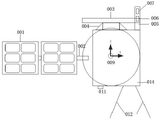
图1是一种基于微小卫星的高分遥感定标系统的结构示意图的正面视图,Figure 1 is a front view of a schematic structural diagram of a microsatellite-based high-resolution remote sensing calibration system,
其中,卫星太阳能帆板已经展开;Among them, satellite solar panels have been deployed;
图2是一种基于微小卫星的高分遥感定标系统的结构示意图的右侧视图;Figure 2 is a right side view of a schematic structural diagram of a microsatellite-based high-resolution remote sensing calibration system;
附图标记说明:001、展开式太阳能板;002、太阳能板承载臂;003、反射镜;004、反射镜法兰;005、探测器安装臂;006、一号探测器;007、二号探测器;008、三号探测器;009、反射球;010、反射球旋转和安装法兰;011、GPS天线;012、数传天线;013、发射安装法兰;014、卫星体。Reference numeral description: 001, unfolding solar panel; 002, solar panel carrying arm; 003, mirror; 004, mirror flange; 005, detector mounting arm; 006, No. 1 detector; 007, No. 2
具体实施方案specific implementation
下面结合附图和实施例对本发明作进一步的说明。The present invention will be further described below with reference to the accompanying drawings and embodiments.
如图1、2所示,一种基于微小卫星的高分遥感定标系统,它包括展开式太阳能板001、太阳能板承载臂002、反射镜003、反射镜法兰004、探测器安装臂005、一号探测器006、二号探测器007、三号探测器008、反射球009、反射球旋转和安装法兰010、GPS天线011、数传天线012、发射安装法兰013、卫星体014;展开式太阳能板001通过太阳能板承载臂002与卫星体014相连;反射镜003通过安装在反射镜法兰004上与卫星体014装配在一起;一号探测器006、二号探测器007、三号探测器008均安装于探测器安装臂005;反射球009通过反射球旋转和安装法兰010装配在卫星体014;GPS天线011和数传天线012装配在卫星体014的底部;卫星体014通过发射安装法兰013可与运载火箭连接。As shown in Figures 1 and 2, a high-resolution remote sensing calibration system based on microsatellites includes an unfolded
所述的反射球009可以通过反射球旋转和安装法兰010结构,可以实现在轨旋转而并不会影响对卫星的姿态产生大纵向的影响,并通过反射球旋转和安装法兰010和一号探测器006实现对整个反射球009的球面360度的探测。The
所采用的反射球009和反射镜003互相配合的结构设计,满足在同一太阳入射条件下两种辐射校准参数的对比,可以有效的提高校准精度。The adopted structure design in which the reflecting
所设计的安装在探测器安装臂005上的一号探测器006、二号探测器007和三号探测器008,其中一号探测器006实现对反射球的反射光进行观测;三号探测器008实现对反射镜003的反射光进行观测;二号探测器007则在同一角度对地面进行观测。The designed No. 1
如图1、2所示,一种所述的一种基于微小卫星的高分遥感定标系统的定标方法,当微小卫星进入外太空预定轨道时,首先展开式太阳能板001和太阳能板承载臂002在接收到卫星的飞行程序的展开指令后进行展开,并开始为整个卫星系统提供电源;然后安装在探测器安装臂005上的一号探测器006、二号探测器007、三号探测器008在卫星飞行程序的控制下,同时拍摄反射球009、地面和反射镜003的反射信息,并记录此时的GPS天线011所接收到的卫星的位置信息,最终所有的信息将通过数传天线012把数据传输到地面进行分析;然而随着时间的推移,反射球009和反射镜003会受空间环境的影响而出现表面反射强度衰减的情况,此时则通过反射球旋转和安装法兰010的旋转实现对整个反射球009可观测面的所有的数据的搜集,来实现反射球009和反射镜003表面反射强度衰减的补偿。As shown in Figures 1 and 2, one of the described calibration methods for a microsatellite-based high-resolution remote sensing calibration system, when the microsatellite enters a predetermined orbit in outer space, firstly the unfolded
Claims (4)
Priority Applications (1)
| Application Number | Priority Date | Filing Date | Title |
|---|---|---|---|
| CN201710909078.9A CN107745830B (en) | 2017-09-29 | 2017-09-29 | A high-resolution remote sensing calibration system and calibration method based on microsatellites |
Applications Claiming Priority (1)
| Application Number | Priority Date | Filing Date | Title |
|---|---|---|---|
| CN201710909078.9A CN107745830B (en) | 2017-09-29 | 2017-09-29 | A high-resolution remote sensing calibration system and calibration method based on microsatellites |
Publications (2)
| Publication Number | Publication Date |
|---|---|
| CN107745830A CN107745830A (en) | 2018-03-02 |
| CN107745830B true CN107745830B (en) | 2020-08-18 |
Family
ID=61256048
Family Applications (1)
| Application Number | Title | Priority Date | Filing Date |
|---|---|---|---|
| CN201710909078.9A Active CN107745830B (en) | 2017-09-29 | 2017-09-29 | A high-resolution remote sensing calibration system and calibration method based on microsatellites |
Country Status (1)
| Country | Link |
|---|---|
| CN (1) | CN107745830B (en) |
Families Citing this family (2)
| Publication number | Priority date | Publication date | Assignee | Title |
|---|---|---|---|---|
| CN111198036B (en) * | 2020-02-17 | 2020-11-27 | 北京理工大学 | Solar Radiation Calibration System and Method for Geostationary Optical Remote Sensors |
| CN111272276B (en) * | 2020-02-17 | 2021-01-05 | 北京理工大学 | Lunar radiation calibration system and method by earth stationary orbit optical remote sensor |
Family Cites Families (7)
| Publication number | Priority date | Publication date | Assignee | Title |
|---|---|---|---|---|
| DE102011016732B3 (en) * | 2011-04-11 | 2012-07-05 | Fraunhofer-Gesellschaft zur Förderung der angewandten Forschung e.V. | Radiometric calibration device with monolithically integrated multiple switch |
| CN102901516B (en) * | 2012-09-29 | 2015-08-19 | 航天恒星科技有限公司 | A kind of multispectral image radiation correction method based on absolute radiometric calibration |
| CN103018736B (en) * | 2012-12-03 | 2014-11-26 | 北京航空航天大学 | Satellite-borne remote sensor radiation calibration method based on atmospheric parameter remote sensing retrieval |
| CN105352609B (en) * | 2015-11-13 | 2018-06-01 | 北京空间飞行器总体设计部 | A kind of Optical remote satellite absolute radiation calibration method based on space lambert's sphere |
| CN105415371A (en) * | 2015-12-01 | 2016-03-23 | 中国科学院上海技术物理研究所 | Two-dimensional pointing mechanism for space optical remote sensing instrument |
| CN106403902B (en) * | 2016-08-31 | 2019-01-04 | 武汉大学 | A kind of optical satellite in-orbit real-time geometry location method and system cooperateed with to star |
| CN106643796B (en) * | 2016-12-02 | 2019-07-12 | 北京空间机电研究所 | A kind of Calibration Method based on in-orbit proper star |
-
2017
- 2017-09-29 CN CN201710909078.9A patent/CN107745830B/en active Active
Also Published As
| Publication number | Publication date |
|---|---|
| CN107745830A (en) | 2018-03-02 |
Similar Documents
| Publication | Publication Date | Title |
|---|---|---|
| CN103605887B (en) | A kind of satellite in orbit imaging rough water sun glitter simulation model for space-time distribution | |
| US9823116B2 (en) | Geometric calibration of a remote sensor | |
| CN105352609B (en) | A kind of Optical remote satellite absolute radiation calibration method based on space lambert's sphere | |
| CN104573251A (en) | Method for determining full-field-of-view apparent spectral radiance of satellite-borne optical remote sensor | |
| CN112526227B (en) | Method and device for measuring antenna direction characteristics of satellite-borne microwave radiometer | |
| US12135372B2 (en) | Method and system for detecting and modeling objects in space using lidar | |
| Zelensky et al. | DORIS/SLR POD modeling improvements for Jason-1 and Jason-2 | |
| Yaohai et al. | FY-4 meteorological satellite | |
| CN111272276B (en) | Lunar radiation calibration system and method by earth stationary orbit optical remote sensor | |
| CN107745830A (en) | A kind of high score remote sensing scaling system and calibrating method based on microsatellite | |
| CN117348017A (en) | A distributed space debris laser ranging system | |
| CN115877412A (en) | A satellite tracking method | |
| Kucharski et al. | Hypertemporal photometric measurement of spaceborne mirrors specular reflectivity for Laser Time Transfer link model | |
| CN110816889A (en) | Remote sensing micro-nano satellite system | |
| CN111198036B (en) | Solar Radiation Calibration System and Method for Geostationary Optical Remote Sensors | |
| CN117348016A (en) | A one-shot and multiple-receiver laser ranging method for low-orbit space debris | |
| CN108871316B (en) | Self-detection device in airborne star sensor | |
| CN107330136B (en) | Layout method of remote sensing satellite navigation antenna suitable for double-side-view work | |
| Thorsteinson | Key findings from the NEOSSat space-based SSA microsatellite mission | |
| Dong et al. | Research on Generalized Celestial Navigation Autonomous Positioning Method for Near-Space Vehicles | |
| Wei | FY-4A Delivers First Batch of Images | |
| Merola et al. | Ejecta plume observability from an asteroid small impactor mission | |
| CN116047403A (en) | Method and system for obtaining pointing information of spaceborne antenna by using distributed multi-satellite sensors | |
| Bézy et al. | System, spacecraft, and instrument concepts for the ESA Earth Explorer EarthCARE Mission | |
| Lederer | NASA Measurements Summary for the IADC Working Group 1 |
Legal Events
| Date | Code | Title | Description |
|---|---|---|---|
| PB01 | Publication | ||
| PB01 | Publication | ||
| SE01 | Entry into force of request for substantive examination | ||
| SE01 | Entry into force of request for substantive examination | ||
| GR01 | Patent grant | ||
| GR01 | Patent grant |