CN107740598B - Tower type cast-in-situ structure formwork support system and construction process thereof - Google Patents
Tower type cast-in-situ structure formwork support system and construction process thereof Download PDFInfo
- Publication number
- CN107740598B CN107740598B CN201711021728.2A CN201711021728A CN107740598B CN 107740598 B CN107740598 B CN 107740598B CN 201711021728 A CN201711021728 A CN 201711021728A CN 107740598 B CN107740598 B CN 107740598B
- Authority
- CN
- China
- Prior art keywords
- arch
- plate
- embedded
- rods
- installation
- Prior art date
- Legal status (The legal status is an assumption and is not a legal conclusion. Google has not performed a legal analysis and makes no representation as to the accuracy of the status listed.)
- Active
Links
Images


Classifications
-
- E—FIXED CONSTRUCTIONS
- E04—BUILDING
- E04G—SCAFFOLDING; FORMS; SHUTTERING; BUILDING IMPLEMENTS OR AIDS, OR THEIR USE; HANDLING BUILDING MATERIALS ON THE SITE; REPAIRING, BREAKING-UP OR OTHER WORK ON EXISTING BUILDINGS
- E04G25/00—Shores or struts; Chocks
-
- E—FIXED CONSTRUCTIONS
- E04—BUILDING
- E04G—SCAFFOLDING; FORMS; SHUTTERING; BUILDING IMPLEMENTS OR AIDS, OR THEIR USE; HANDLING BUILDING MATERIALS ON THE SITE; REPAIRING, BREAKING-UP OR OTHER WORK ON EXISTING BUILDINGS
- E04G25/00—Shores or struts; Chocks
- E04G25/02—Shores or struts; Chocks non-telescopic
-
- E—FIXED CONSTRUCTIONS
- E04—BUILDING
- E04G—SCAFFOLDING; FORMS; SHUTTERING; BUILDING IMPLEMENTS OR AIDS, OR THEIR USE; HANDLING BUILDING MATERIALS ON THE SITE; REPAIRING, BREAKING-UP OR OTHER WORK ON EXISTING BUILDINGS
- E04G25/00—Shores or struts; Chocks
- E04G2025/003—Supports therefor, e.g. tripods
Abstract
The invention discloses a formwork supporting system of a tower type cast-in-place structure and a construction process thereof, wherein the formwork supporting system comprises a plurality of arches which are arranged at intervals and are arranged in parallel in a row, the bottom ends of the arches are fixed on a ground beam, a plurality of baffle plates with tightly attached side edges are fixedly arranged between the adjacent arches, or a protective net covers all the arches; the baffle plates completely cover gaps between the adjacent arch frames and form an arched storage space with the ground beam; a plurality of rows of upright rods are fixedly arranged on each arch centering and on the left side and the right side of all the arch centering, and the upright rods are arranged in a stepped layered manner according to the size and the specification of a tower building to be erected; the mounting steps of the support system mainly comprise: the method comprises the steps of early preparation, arch foot fixing, arch center installation, baffle installation, upright rod support installation on the arch center and support frame installation. The tower type cast-in-place structure formwork support system and the construction process thereof have the advantages of convenience in construction, short construction period, material saving and material accumulation space.
Description
Technical Field
The invention relates to a template support system of a tower type building, in particular to a template support system of a tower type cast-in-place structure and a construction process thereof.
Background
The tower building is a step-shaped building with the diameters decreasing from bottom to top layer by layer. At present, when a building of the type is built, a full framing scaffold is required to be used as a supporting system of the formwork. During the erection process, the steel pipe and the template are vertically transported and horizontally transported to corresponding positions for many times. This results in a long construction period, and therefore, often in order to speed up the progress, constructors can meet the requirements of material turnover and construction progress by increasing turnover material input. However, the area of the construction site is limited, a full scaffold needs to be erected in the limited area, and the scaffold occupies most space, so that the material stacking area is insufficient, and the construction progress is influenced. Meanwhile, the mode of erecting the scaffold by the full framing scaffold is very wasted in materials, the erection area is too large, and certain influence is caused on the construction progress.
Disclosure of Invention
Aiming at the defects of the prior art, the technical problems to be solved by the invention are as follows:
the formwork support system of the existing building is generally realized by adopting a full framing scaffold mode, and the mode has the defects of more materials, large erection area, slow construction progress and incapability of meeting the requirement of material stacking.
In order to solve the technical problems, the invention adopts the following technical scheme:
a tower type cast-in-place structural formwork supporting system is characterized by comprising a plurality of arch frames which are arranged at intervals and are arranged in parallel in a row, wherein the bottom ends of the arch frames are fixed on a ground beam, a plurality of baffle plates with side edges clinging to each other are fixedly arranged between the adjacent arch frames, or a protective net covers all the arch frames; the baffle plates completely cover gaps between the adjacent arch frames and form an arched storage space with the ground beam; the tower type building is characterized in that a plurality of rows of vertical rods are fixedly mounted on each arch centering and on the left side and the right side of each arch centering, the vertical rods are arranged in a stepped layered mode according to the size and the specification of a tower type building to be erected, and a plurality of transverse rods which are arranged transversely and longitudinally are fixedly mounted on each row of vertical rods. Through the arrangement of the arch centering, and the support frame bodies are arranged on the arch centering and on two sides of the arch centering, so that the erection number of the support frame bodies is reduced, the erection material of the frame bodies is saved, and the construction period can be shortened. Simultaneously, the arch storing space that middle part bow member and grade beam formed provides sufficient space for stacking of material, can be convenient for constructor to manage the material in an orderly manner and discharge the condition, simultaneously, can also shorten the transport route of material, provide very big facility for the construction.
Furthermore, each arch center is formed by fixedly connecting a plurality of I-beams with different radians, two ends of each I-beam are fixedly provided with a mounting plate, the mounting plates are fixed with the ends of the I-beams in a welding mode, four corners of each mounting plate are provided with a threaded hole, the mounting plates of adjacent I-beams are fixed by welding, penetrate through the threaded holes through bolts and are fixedly connected; and each arch center penetrates through the mounting plate and the pre-buried steel plate of the fixed ends on the left side and the right side of the arch center and then is fixed on the ground beam through the pre-buried anchor rods. The arch center is formed by connecting a plurality of I-beams, and when the arch center is installed, a plurality of persons can operate simultaneously, so that the assembly time is saved, the mounting plates welded at the two ends of each I-beam provide larger connecting area and space for the I-beam connecting end, and the adjacent I-beam mounting plates are fixed in a mode of combining welding and a fastener, so that double guarantee is provided between the I-beams, and the connection is very stable. Meanwhile, the arch center and the ground beam are fixed in a mode that the embedded anchor rods, the embedded steel plates and the I-shaped steel mounting plates are welded with each other, and the connecting structure is very stable.
Furthermore, the equal fixed mounting in the middle waist of every I-steel has the angle sign indicating number of at least one L shape, the angle sign indicating number sets up towards the bow member central direction to form a half enclosure space with the I-steel upside half enclosure space intussuseption is filled with the concrete cushion that the up end is parallel with the horizontal plane and is used for supporting the pole setting on the bow member, and every concrete cushion corresponds a pole setting, is equipped with a wooden square column between pole setting and concrete cushion. Through welding the angle sign indicating number on the I-steel to at angle sign indicating number place space filling concrete cushion, provide sufficient mounting platform for placing of pole setting. And the placed wood balk is mainly used for reducing the damage of the vertical rod to the concrete cushion.
Further, the baffle includes regulating plate and fixed plate, regulating plate and fixed plate overlap the setting from top to bottom, and overlap sliding type connection can be spacing, and the outer end of regulating plate and fixed plate articulates respectively in the preceding waist and the back waist of two adjacent I-steel. The baffle is set to be adjustable, so that when the baffle is installed, a large enough space can be provided for one end to be installed later, and then the baffle is adjusted to be fixed after being adjusted to a proper length.
Further, regulating plate wherein one end is equipped with two at least first couples, and the left and right sides of the other end all is fixed with at least one buckle, and the regulating plate is equipped with the one end of buckle and is equipped with at least one bar hole that sets up along its length direction, the wherein one end of fixed plate is equipped with two at least second couples, and the other end middle part is equipped with at least one screw hole, regulating plate and fixed plate articulate with the I-steel through first couple and second couple respectively, and the buckle joint of regulating plate both sides is in the fixed plate both sides to can slide along fixed plate length direction, behind regulating plate and the fixed plate overlap portion pass through the screw hole of regulating plate and the bar hole of fixed plate through the bolt, it is fixed with the lock nut cooperation. The tail end of the fixing plate and the adjusting plate is connected with the I-shaped steel in a hanging mode through the hooks, the fixing plate and the adjusting plate are connected in a sliding mode through the buckled mode, the strip-shaped holes are formed in the fixing plate and the adjusting plate, the bolts can move in the length direction of the strip-shaped holes, sliding spaces are further provided for the adjusting plate and the fixing plate, the buckle plate is combined with the bolt locking mode, and connection between the fixing plate and the adjusting plate can be increased in a dual mode.
A construction process of a tower type cast-in-situ structural formwork support system is characterized by comprising the following steps: step one, drawing a construction drawing by using cad, and preparing materials according to a material table after listing the material table; secondly, pouring concrete ground beams, and embedding anchor rods and embedded steel plates at the fixed end positions of the left side and the right side of each arch frame according to the requirements of construction drawings; step three, installing arch frames one by one, wherein during installation, the installation sequence of the arch frames is that the arch feet on two sides are installed from bottom to top, and finally the arch frames are folded in the middle of the top; step four, sequentially laying and fixing a layer of protective net and a layer of baffle between adjacent arch frames until all the arch frames are sealed; installing a horizontal cushion layer of the vertical rod on the arch truss, specifically, according to a construction drawing, welding a corner brace on the I-steel of each arch truss, pouring a concrete cushion layer, and placing a wood purlin on each concrete cushion layer; and step six, erecting vertical rods and cross rods on two sides of the arch centering and on the arch centering according to a construction drawing to form a step-shaped support frame body.
Furthermore, four corners on the pre-buried steel plate in the second step are provided with anchor rods for penetrating holes, positioning lines of the pre-buried steel plate are required to be popped out on the foundation cushion layer by adopting an ink fountain before the pre-buried anchor rods, the pre-buried anchor rods are correspondingly sleeved on the pre-buried anchor rods according to the positions of the holes penetrated by the anchor rods in the pre-buried steel plate after the anchor rods are pre-buried, and then the anchor rods are fixed with the pre-buried steel plates together by adopting a welding mode.
Further, the specific installation steps of the arch centering in the step three are as follows: s1, stacking and discharging materials according to the shape and the number of I-shaped steel required by each arch frame; s2, welding a mounting plate at the left end and the right end of each I-shaped steel; and S3, fixing and installing corresponding I-beams from the arch foot to the top in sequence until the top is folded, fully welding the periphery of the installation plate between the adjacent I-beams during installation, penetrating the threaded holes in the installation plate through bolts, locking the installation plate through nuts, aligning the threaded holes of the installation plate to the embedded anchor rods and sleeving the embedded anchor rods when the installation plate of the I-beams at the arch foot is installed, and then welding the periphery of the installation plate to the periphery of the embedded steel plate.
Furthermore, an adjustable U-shaped jacking is arranged at the top end of each vertical rod, a floor sweeping rod is arranged at the position, 200mm high away from the arch frame, of the bottom of each vertical rod, along the vertical and horizontal directions according to the vertical and horizontal procedures, a horizontal pull rod is arranged at the top end of each vertical rod along the vertical and horizontal directions, and continuous type bridging is arranged at the end parts of all the horizontal pull rods.
Compared with the prior art, the tower type cast-in-place structure formwork support system and the construction process thereof have the following advantages:
1. through setting up the bow member on the construction site to on the bow member and the both sides of bow member set up the support frame body, reduced the consumption of setting up engineering volume and support material of supporting the frame body, simultaneously, the bow member at middle part can provide storage space for the required material of support system with the storing space that the grade beam formed, makes the space distribution more reasonable, and the management and the stack of the material of being convenient for more, has reduced the transport volume of material.
2. The arch center is formed by connecting a plurality of I-shaped steels end to end, the joints are fixed by adopting a mode of combining welding and fasteners, and the structure is very stable. And the baffle of installation not only can keep out the wind and keep out the rain between the adjacent bow member, avoids the material to appear damaging after the insolate or drench, can also prevent to drop debris from the top in the working process, influences construction or rest personnel's safety.
Drawings
FIG. 1 is a schematic elevation structure diagram of a tower type cast-in-place structure formwork supporting system in an embodiment;
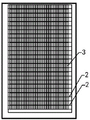
FIG. 2 is a schematic diagram showing the distribution structure of baffles in the example;
FIG. 3 is a schematic view of a connection structure of an arch springing and a ground beam of the arch center in the embodiment;
FIG. 4 is a schematic view of a connection structure between I-beams in the embodiment;
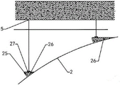
FIG. 5 is a schematic structural view of the installation of the vertical rods on the arch in the embodiment;
FIG. 6 is a schematic view of a connecting structure between a baffle plate and an I-shaped steel in the embodiment.
In the figure: the structure comprises a ground beam 1, an embedded steel plate 11, an embedded anchor rod 12, an arch frame 2, I-steel 21, an installation plate 22, threaded holes 23, bolts 24, corner connectors 25, a concrete cushion layer 26, wood purlin 27, a baffle 3, an adjusting plate 31, a first hook 311, a buckle plate 312, a strip-shaped hole 313, a fixing plate 32, a second hook 321, an arched storage space 4, a vertical rod 5 and a cross rod 6.
Detailed Description
The invention is further illustrated by the following examples in conjunction with the drawings.
Example (b):
as shown in fig. 1 and fig. 2, the formwork support system for a tower-type cast-in-place structure and the construction process thereof provided by the present embodiment include a plurality of arches 2 arranged in parallel in a row at intervals, wherein the bottom ends of the arches are fixed on a ground beam 1, a plurality of baffles 3 with tightly attached side edges are fixedly installed between adjacent arches 2, or a protective net covers all the arches 2; the baffle 3 completely covers gaps between the adjacent arch frames 2 and forms an arch-shaped storage space 4 with the ground beam 1; a plurality of rows of upright rods 5 are fixedly arranged on each arch frame 2 and on the left side and the right side of all the arch frames 2, the upright rods 5 are arranged in a stepped layered manner according to the size and specification of a tower building to be erected, and a plurality of transverse rods 6 which are transversely and longitudinally arranged are fixedly arranged on each row of upright rods 5.
As shown in fig. 3 and 4, in the present embodiment, the node of the arch 2 is at the same level as the floor level, and the specific structure of the arch 2 is as follows: each arch center 2 is formed by fixedly connecting a plurality of I-beams 21 with different radians, two ends of each I-beam 21 are fixedly provided with a mounting plate 22, the mounting plates 22 are fixed with the ends of the I-beams 21 in a welding mode, four corners of each mounting plate 22 are provided with threaded holes 23, the mounting plates 22 of adjacent I-beams 21 are fixed by welding, and penetrate through the threaded holes 23 through bolts 24 to be fixedly connected; an embedded steel plate 11 and at least two embedded anchor rods 12 are arranged in the ground beam 1 corresponding to the fixed ends of the left side and the right side of each arch centering 2, and each arch centering 2 penetrates through the mounting plates 22 of the fixed ends of the left side and the right side of each arch centering 2 and the embedded steel plates 11 through the embedded anchor rods 12 and then is fixed on the ground beam 1. The embedded anchor rod 12 is a hollow anchor rod, the outer surface of the embedded anchor rod is threaded to increase contact with concrete, and the inner surface of the embedded anchor rod is smooth to facilitate insertion of a long threaded rod.
As shown in fig. 5, the concrete installation structure of the vertical rod 5 and the i-steel 21 is as follows: the equal fixed mounting in the middle waist portion of every I-steel 21 has the angle sign indicating number 25 of at least one L shape, angle sign indicating number 25 sets up towards 2 central directions of bow member to form a half enclosure space with the I-steel 21 upside fill in the half enclosure space and be filled with the concrete cushion 26 that up end and horizontal plane are parallel and be used for supporting the bow member and go up the pole, every concrete cushion 26 corresponds a pole setting 5, is equipped with a wood purlin 27 between pole setting 5 and concrete cushion 26, and the thickness of wood purlin is not less than 50mm, the width is not less than 200mm.
Above-mentioned baffle 3 includes regulating plate 31 and fixed plate 32, regulating plate 31 and fixed plate 32 are the overlapping setting from top to bottom, and overlap sliding type connection and can be spacing, and the outer end of regulating plate 31 and fixed plate 32 articulates respectively in the preceding waist and the back waist of two adjacent I-steel 21. When in use, the baffle 3 can be made of an aluminum buckle plate with the thickness of 1 cm.
As shown in fig. 6, adjusting plate 31 wherein one end is equipped with two at least first couples 311, and the left and right sides of the other end all is fixed with at least one buckle 312, and the one end that adjusting plate 31 was equipped with buckle 312 is equipped with at least one bar hole 313 that sets up along its length direction, the wherein one end of fixed plate 32 is equipped with two at least second couples 321, and the other end middle part is equipped with at least one screw hole, adjusting plate 31 and fixed plate 32 articulate with I-steel 21 through first couple 311 and second couple 321 respectively, and the buckle 312 joint of adjusting plate 31 both sides is in fixed plate 32 both sides to can slide along fixed plate 32 length direction, adjusting plate 31 and fixed plate 32 overlap portion pass through behind the screw hole of adjusting plate 31 and the bar hole 313 of fixed plate 32 through the bolt, fixed with the lock nut cooperation.
Aiming at the support system, the embodiment also provides a construction process of the tower type cast-in-place structure formwork support system, which comprises the following steps: step one, drawing a construction drawing by using cad, and preparing materials according to a material table after listing the material table; secondly, pouring the concrete ground beam 1, and embedding anchor rods 12 and embedded steel plates 11 at the fixed end positions of the left side and the right side of each arch frame 2 according to the requirements of construction drawings; step three, installing the arch frames 2 one by one, wherein during installation, sectional manufacturing, transportation and installation are adopted, the installation sequence of the arch frames 2 is that the arch feet at two sides are installed from bottom to top, and finally the arch frames are folded at the middle of the top; step four, sequentially laying and fixing a layer of protective net and a baffle 3 between adjacent arch frames 2 until all the arch frames 2 are sealed; step five, mounting horizontal cushion layers of the vertical rods 5 on the arch frames 2, specifically, according to a construction drawing, welding angle codes 25 of 100mm x 8mm on the I-steel 21 of each arch frame 2, pouring concrete cushion layers 26, and placing one wood brace 27 on each concrete cushion layer 26; and step six, erecting upright posts 5 and cross bars 6 on two sides of the arch frame 2 and the arch frame 2 according to a construction drawing to form a step-shaped support frame body.
In the first step, in the material preparation stage, the specification of the embedded steel plate 11 is 400mm 10mm, and during manufacturing, the embedded steel plate is cut into a square by a plate shearing machine in a processing factory, the length and width dimensions are controlled between plus and minus 1mm, and the thickness is not less than 8mm.
Four corners on the embedded steel plate 11 in the second step are provided with anchor rod through holes, before embedding the embedded anchor rod 12, an ink fountain needs to be adopted to pop out the positioning lines of the embedded steel plate 11 on the foundation cushion layer, the anchor rod 12 is embedded according to the positions of the anchor rod through holes in the embedded steel plate 11, after the embedded anchor rod 12 is embedded, the embedded steel plate 11 is correspondingly sleeved on the embedded anchor rod 12, and then the embedded anchor rod 12 and the embedded steel plate 11 are fixed together in a welding mode. In the embedding process, the embedded steel plates 11 are required to be tightly attached to the template, the influence is small when the deviation from the upper part to the lower part, the left part to the right part and the front part to the rear part is 20mm, and the direct contact between the corner connectors and the embedded steel plates 11 is reduced due to the fact that the angle connectors are inclined from the front part to the rear part.
The arch center in the third step comprises the following specific installation steps: s1, stacking and discharging materials according to the shape and the number of the required I-steel 21 of each arch frame 2; s2, welding a mounting plate 22 at the left end and the right end of each I-shaped steel 21; and S3, fixing and installing the corresponding I-beams 21 from the arch springing position from bottom to top in sequence until the top is folded, fully welding the peripheries of the installation plates 22 between the adjacent I-beams 21 during installation, penetrating the threaded holes in the installation plates through bolts, locking the installation plates 22 by nuts, aligning the threaded holes of the installation plates 22 to the embedded anchor rods 12 and sleeving the embedded anchor rods 12 during installation of the installation plates 22 of the I-beams 21 at the arch springing position, and then welding the peripheries of the installation plates 22 to the peripheries of the embedded steel plates 11.
In the fourth step, the concrete installation process of the baffle 3 is as follows: assembling the adjusting plate 31 and the fixing plate 32 to form a plurality of baffle plates 3, hanging hooks at one end of each baffle plate 3 on a waist plate at one side of the I-steel, sliding the fixing plate 32 according to the distance between the arch frames 2 until the fixing plate extends out of the middle part of the adjacent I-steel 21, sliding the other end of each baffle plate 3 back until the fixing plate is tightly attached to the waist part of the adjacent I-steel 21, and finally, rotating the nut to fix the adjusting plate 31 and the fixing plate 32 together to complete the installation of one baffle plate 3. The remaining baffle plates 3 may be sequentially installed in the above-described manner.
The adjustable U-shaped jacking device comprises upright posts 5 and a positioning nut, wherein the upright posts 5 are made of steel pipes, an adjustable U-shaped jacking is arranged at the top end of each upright post 5, each adjustable U-shaped jacking comprises a vertically arranged steel pipe, a screw rod and a supporting plate arranged at the tail end of the screw rod, one end of each screw rod is sleeved in the steel pipe, an adjustable mounting support is arranged at the upper end and/or the lower end of each steel pipe, each adjustable mounting support comprises a mounting cylinder, two semicircular arc-shaped buckling plates symmetrically arranged at two sides of the mounting cylinder and a positioning nut connected with the mounting cylinder and positioned in the arc-shaped buckling plates; the arc-shaped buckling plates can be rotatably connected to the left side and the right side of the installation cylinder, the tail ends of the arc-shaped buckling plates can be fixedly connected through bolts, and the two arc-shaped buckling plates are closed to form a cylinder and used for clamping a steel pipe; the positioning nut is matched with the steel pipe, and a center hole of the positioning nut is in threaded connection with the screw rod. The adjustable U-shaped jacking and the clearance at two sides of the stupefied beam must be wedged tightly, the screw rod of the adjustable U-shaped jacking and the top of the upright rod 5 must not be larger than 200mm, the clearance between the outer diameter of the screw rod and the inner diameter of the steel pipe of the upright rod 5 must not be larger than 3mm, and the adjustable U-shaped jacking and the stupefied beam are concentric up and down during installation. At 5 bottoms of pole setting 200mm eminences apart from the bow member, along moving about freely and quickly the horizontal direction according to indulge down horizontal procedure and be provided with the pole of sweeping the ground, 5 tops of pole setting respectively are provided with one horizontal pull rod along moving about freely and quickly the direction, and the tip of all horizontal pull rods is provided with continuous type bridging, and bridging adopts the overlap joint, and overlap joint length is not less than 500mm to adopt 2 rotatory fasteners to fix from the rod end respectively is not less than 100mm department.
It should be noted that, although the above embodiments are only used for illustrating the technical solutions of the present invention and not for limiting the technical solutions, the applicant has described the technical solutions of the present invention in detail with reference to the preferred embodiments, and it should be understood by those skilled in the art that modifications or equivalent substitutions may be made to the technical solutions of the present invention without departing from the spirit and scope of the technical solutions, and all the technical solutions are covered by the claims of the present invention.
Claims (9)
1. A tower type cast-in-place structure formwork supporting system is characterized by comprising a plurality of arch frames (2) which are arranged at intervals and are arranged side by side in a row, wherein the bottom ends of the arch frames are fixed on a ground beam (1), a plurality of baffle plates (3) with side edges being clung to each other are fixedly arranged between the adjacent arch frames (2), or a protective net covers all the arch frames (2); the baffle (3) completely covers gaps between the adjacent arch frames (2) and forms an arched storage space (4) with the ground beam (1); a plurality of rows of upright rods (5) are fixedly mounted on each arch frame (2) and the left side and the right side of each arch frame (2), each arch frame (2) is formed by fixedly connecting a plurality of I-shaped steels (21) with different radians, at least one L-shaped angle brace (25) is fixedly mounted at the middle waist part of each I-shaped steel (21), each angle brace (25) is arranged in the direction facing the center of each arch frame (2) and forms a semi-surrounding space with the upper side of each I-shaped steel (21), a concrete cushion layer (26) with the upper end surface parallel to the horizontal plane and used for supporting the upright rods on the arch frames is filled in the semi-surrounding space, and each concrete cushion layer (26) corresponds to one upright rod (5); the upright posts (5) are arranged in a stepped layered manner according to the size and specification of a tower building to be erected, and a plurality of transverse rods (6) which are transversely and longitudinally arranged are fixedly arranged on each row of upright posts (5).
2. The tower type cast-in-place structural formwork support system according to claim 1, wherein two ends of each I-steel (21) are fixedly provided with a mounting plate (22), the mounting plates (22) are fixed with the ends of the I-steels (21) in a welding mode, four corners of each mounting plate (22) are provided with a threaded hole (23), the mounting plates (22) of adjacent I-steels (21) are fixed through welding, and are fixedly connected after penetrating through the threaded holes (23) through bolts (24); an embedded steel plate (11) and at least two embedded anchor rods (12) are arranged in the ground beam (1) corresponding to the fixed ends of the left side and the right side of each arch centering (2), and each arch centering (2) penetrates through the mounting plates (22) of the fixed ends of the left side and the right side of each arch centering (2) and the embedded steel plates (11) through the embedded anchor rods (12) and is then fixed on the ground beam (1).
3. The tower cast-in-place structural formwork support system as claimed in claim 2, wherein a wood purlin (27) is provided between the upright (5) and the concrete pad (26).
4. The tower type cast-in-place structural formwork support system according to claim 2, wherein the baffle (3) comprises an adjusting plate (31) and a fixing plate (32), the adjusting plate (31) and the fixing plate (32) are arranged in an up-down overlapping mode, the overlapped parts are connected in a sliding mode and can limit the position, and the outer ends of the adjusting plate (31) and the fixing plate (32) are respectively hung at the front waist part and the rear waist part of two adjacent I-shaped steels (21).
5. The tower type cast-in-place structure formwork support system according to claim 4, wherein one end of the adjusting plate (31) is provided with at least two first hooks (311), the left side and the right side of the other end of the adjusting plate are both fixed with at least one buckle plate (312), one end of the adjusting plate (31) provided with the buckle plate (312) is provided with at least one strip-shaped hole (313) arranged along the length direction of the adjusting plate, one end of the fixing plate (32) is provided with at least two second hooks (321), the middle part of the other end of the adjusting plate is provided with at least one threaded hole, the adjusting plate (31) and the fixing plate (32) are respectively hooked with the I-shaped steel (21) through the first hooks (311) and the second hooks (321), the buckle plates (312) on the two sides of the adjusting plate (31) are clamped on the two sides of the fixing plate (32) and can slide along the length direction of the fixing plate (32), and the overlapped part of the adjusting plate (31) and the fixing plate (32) penetrates through the threaded hole of the adjusting plate (31) and the strip-shaped hole (313) of the fixing plate (32) through a bolt and then is matched and fixed with a locking nut.
6. A construction process of a tower type cast-in-situ structure formwork support system is characterized by comprising the following steps: step one, drawing a construction drawing by using cad, and preparing materials according to a material table after listing the material table; secondly, pouring a concrete ground beam (1), and embedding anchor rods (12) and embedded steel plates (11) at the fixed end positions of the left side and the right side of each arch frame (2) according to the requirements of construction drawings; step three, installing the arch frames (2) one by one, wherein during installation, the installation sequence of the arch frames (2) is that the arch feet at two sides are installed from bottom to top, and finally the arch frames are folded at the middle of the top; step four, sequentially laying and fixing a layer of protective net and a baffle (3) between adjacent arch frames (2) until all the arch frames (2) are sealed; fifthly, installing a horizontal cushion layer of the vertical rod (5) on the arch frames (2), specifically, according to a construction drawing, welding corner connectors (25) on the I-shaped steel (21) of each arch frame (2), pouring concrete cushion layers (26), and placing a wood purlin (27) on each concrete cushion layer (26); and step six, erecting vertical rods (5) and cross rods (6) on two sides of the arch frame (2) and the arch frame (2) according to a construction drawing to form a step-shaped support frame body.
7. The construction process of the tower type cast-in-place structure formwork support system according to claim 6, wherein an anchor rod penetrating hole is formed in each of four corners of the embedded steel plate (11) in the second step, before the embedded anchor rod (12) is embedded, an ink fountain needs to be adopted to pop out a positioning line of the embedded steel plate (11) on a foundation cushion layer, the anchor rod (12) is embedded according to the position of the anchor rod penetrating hole in the embedded steel plate (11), after the embedded anchor rod (12) is embedded, the embedded steel plate (11) is correspondingly sleeved on the embedded anchor rod (12), and then the embedded anchor rod (12) and the embedded steel plate (11) are fixed together in a welding mode.
8. The construction process of the tower type cast-in-situ structural formwork support system according to claim 6, characterized in that the concrete installation steps of the arch frame in the third step are as follows: s1, stacking and discharging materials according to the shape and the number of the required I-steel (21) of each arch frame (2); s2, welding a mounting plate (22) at the left end and the right end of each I-shaped steel (21); s3, fixing and installing the corresponding I-beams (21) from bottom to top from the arch foot until the top is folded, fully welding the peripheries of the installation plates (22) between the adjacent I-beams (21) during installation, penetrating the threaded holes in the installation plates through bolts, locking the installation plates with nuts, aligning the threaded holes of the installation plates (22) to the embedded anchor rods (12) and sleeving the embedded anchor rods (12) when the installation plates (22) of the I-beams (21) at the arch foot are installed, and then welding the peripheries of the installation plates (22) and the peripheries of the embedded steel plates (11).
9. The construction process of the tower type cast-in-place structural formwork support system according to claim 6, wherein an adjustable U-shaped jacking is arranged at the top end of each upright post (5), floor sweeping rods are arranged at the positions, 200mm away from an arch frame, of the bottoms of the upright posts (5) along the longitudinal and horizontal directions according to the longitudinal, downward and transverse procedures, horizontal pull rods are arranged at the top ends of the upright posts (5) along the longitudinal and horizontal directions respectively, and continuous type cross braces are arranged at the end parts of all the horizontal pull rods.
Priority Applications (1)
| Application Number | Priority Date | Filing Date | Title |
|---|---|---|---|
| CN201711021728.2A CN107740598B (en) | 2017-10-26 | 2017-10-26 | Tower type cast-in-situ structure formwork support system and construction process thereof |
Applications Claiming Priority (1)
| Application Number | Priority Date | Filing Date | Title |
|---|---|---|---|
| CN201711021728.2A CN107740598B (en) | 2017-10-26 | 2017-10-26 | Tower type cast-in-situ structure formwork support system and construction process thereof |
Publications (2)
| Publication Number | Publication Date |
|---|---|
| CN107740598A CN107740598A (en) | 2018-02-27 |
| CN107740598B true CN107740598B (en) | 2023-01-17 |
Family
ID=61238202
Family Applications (1)
| Application Number | Title | Priority Date | Filing Date |
|---|---|---|---|
| CN201711021728.2A Active CN107740598B (en) | 2017-10-26 | 2017-10-26 | Tower type cast-in-situ structure formwork support system and construction process thereof |
Country Status (1)
| Country | Link |
|---|---|
| CN (1) | CN107740598B (en) |
Families Citing this family (1)
| Publication number | Priority date | Publication date | Assignee | Title |
|---|---|---|---|---|
| CN109458195B (en) * | 2018-12-26 | 2020-06-09 | 中国建筑第八工程局有限公司 | Construction method of tunnel secondary lining under condition of small turning radius |
Citations (4)
| Publication number | Priority date | Publication date | Assignee | Title |
|---|---|---|---|---|
| CN102505708A (en) * | 2011-10-21 | 2012-06-20 | 中冶建工集团有限公司 | Construction method of tunnel at oversized cross section open cut area in track traffic |
| CN104234418A (en) * | 2013-12-06 | 2014-12-24 | 绍兴文理学院 | Early removal formwork for fabrication of reinforced concrete beams and construction method thereof |
| CN204876514U (en) * | 2015-08-31 | 2015-12-16 | 合肥建工集团有限公司 | Outer hanging scaffold system of assembled house |
| CN207348497U (en) * | 2017-10-26 | 2018-05-11 | 中冶建工集团有限公司 | Tower cast-in-place structural form bracing system |
Family Cites Families (1)
| Publication number | Priority date | Publication date | Assignee | Title |
|---|---|---|---|---|
| US6981348B2 (en) * | 2002-08-15 | 2006-01-03 | Dale Kjorsvik | Flashing for an exterior arched surface and method |
-
2017
- 2017-10-26 CN CN201711021728.2A patent/CN107740598B/en active Active
Patent Citations (4)
| Publication number | Priority date | Publication date | Assignee | Title |
|---|---|---|---|---|
| CN102505708A (en) * | 2011-10-21 | 2012-06-20 | 中冶建工集团有限公司 | Construction method of tunnel at oversized cross section open cut area in track traffic |
| CN104234418A (en) * | 2013-12-06 | 2014-12-24 | 绍兴文理学院 | Early removal formwork for fabrication of reinforced concrete beams and construction method thereof |
| CN204876514U (en) * | 2015-08-31 | 2015-12-16 | 合肥建工集团有限公司 | Outer hanging scaffold system of assembled house |
| CN207348497U (en) * | 2017-10-26 | 2018-05-11 | 中冶建工集团有限公司 | Tower cast-in-place structural form bracing system |
Also Published As
| Publication number | Publication date |
|---|---|
| CN107740598A (en) | 2018-02-27 |
Similar Documents
| Publication | Publication Date | Title |
|---|---|---|
| CN110374612B (en) | Shield machine receiving platform applied to near-empty state and construction process | |
| CN112411391A (en) | Single-column capping beam steel pipe column Bailey beam construction supporting system and construction method thereof | |
| CN109139049B (en) | Construction method for secondary lining buckling arch of underground excavation station of subway | |
| CN107435335A (en) | Brick retaining wall steel bar girder hardened system and method on foundation pit enclosure top beam | |
| CN116480133A (en) | Supporting system and method for Gaussian curved surface bare concrete construction formwork in sea environment | |
| WO2020098394A1 (en) | Gob-side entry confined concrete supporting construction device and mechanized construction method | |
| CN107740598B (en) | Tower type cast-in-situ structure formwork support system and construction process thereof | |
| CN205369229U (en) | But walking hoisting frame suitable for manual hole digging pile steel reinforcement cage is laid | |
| CN111424948A (en) | Construction method and construction platform for cantilever structure layer of high-rise building | |
| CN111042575A (en) | Steel structure upright post reinforcing structure and method for basement roof temporary road | |
| CN109252661B (en) | Construction method for quick disassembly and quick rotation of lattice beam and high beam slab formwork of clean workshop | |
| CN212201400U (en) | Assembled steel structure external hanging type protective frame | |
| CN114319809A (en) | Construction method of ultrahigh operation platform disc buckle type operation scaffold system | |
| CN210216705U (en) | Urban underground space concrete pouring formwork system | |
| CN111608691B (en) | Shield working well template support construction method | |
| CN110656787A (en) | Protection device for building interior demolition and use method thereof | |
| CN206418817U (en) | A kind of assembled arch steel machining shed | |
| CN209760871U (en) | Transfinite beam support system | |
| CN114108642B (en) | Parallel construction method for ramp bridge and underground complex structure | |
| CN212271228U (en) | Jig frame system for building truss in complex terrain | |
| CN212825316U (en) | Prefabricated interior wallboard storage rack | |
| CN218881583U (en) | Constructional column construction supporting template | |
| CN216428010U (en) | Cast-in-place beam support of ramp bridge | |
| CN112411753B (en) | Construction method of large-span suspended steel truss girder structure | |
| CN215052133U (en) | Steel case roof beam is alternately construction supporting structure from top to bottom |
Legal Events
| Date | Code | Title | Description |
|---|---|---|---|
| PB01 | Publication | ||
| PB01 | Publication | ||
| SE01 | Entry into force of request for substantive examination | ||
| SE01 | Entry into force of request for substantive examination | ||
| GR01 | Patent grant | ||
| GR01 | Patent grant |