CN107736024B - Method and apparatus for video processing - Google Patents
Method and apparatus for video processing Download PDFInfo
- Publication number
- CN107736024B CN107736024B CN201680032461.4A CN201680032461A CN107736024B CN 107736024 B CN107736024 B CN 107736024B CN 201680032461 A CN201680032461 A CN 201680032461A CN 107736024 B CN107736024 B CN 107736024B
- Authority
- CN
- China
- Prior art keywords
- codewords
- color values
- processing
- inverse
- post
- Prior art date
- Legal status (The legal status is an assumption and is not a legal conclusion. Google has not performed a legal analysis and makes no representation as to the accuracy of the status listed.)
- Active
Links
Images


Classifications
-
- H—ELECTRICITY
- H04—ELECTRIC COMMUNICATION TECHNIQUE
- H04N—PICTORIAL COMMUNICATION, e.g. TELEVISION
- H04N19/00—Methods or arrangements for coding, decoding, compressing or decompressing digital video signals
- H04N19/10—Methods or arrangements for coding, decoding, compressing or decompressing digital video signals using adaptive coding
- H04N19/169—Methods or arrangements for coding, decoding, compressing or decompressing digital video signals using adaptive coding characterised by the coding unit, i.e. the structural portion or semantic portion of the video signal being the object or the subject of the adaptive coding
- H04N19/186—Methods or arrangements for coding, decoding, compressing or decompressing digital video signals using adaptive coding characterised by the coding unit, i.e. the structural portion or semantic portion of the video signal being the object or the subject of the adaptive coding the unit being a colour or a chrominance component
-
- H—ELECTRICITY
- H04—ELECTRIC COMMUNICATION TECHNIQUE
- H04N—PICTORIAL COMMUNICATION, e.g. TELEVISION
- H04N19/00—Methods or arrangements for coding, decoding, compressing or decompressing digital video signals
- H04N19/10—Methods or arrangements for coding, decoding, compressing or decompressing digital video signals using adaptive coding
- H04N19/102—Methods or arrangements for coding, decoding, compressing or decompressing digital video signals using adaptive coding characterised by the element, parameter or selection affected or controlled by the adaptive coding
- H04N19/117—Filters, e.g. for pre-processing or post-processing
-
- H—ELECTRICITY
- H04—ELECTRIC COMMUNICATION TECHNIQUE
- H04N—PICTORIAL COMMUNICATION, e.g. TELEVISION
- H04N19/00—Methods or arrangements for coding, decoding, compressing or decompressing digital video signals
- H04N19/10—Methods or arrangements for coding, decoding, compressing or decompressing digital video signals using adaptive coding
- H04N19/134—Methods or arrangements for coding, decoding, compressing or decompressing digital video signals using adaptive coding characterised by the element, parameter or criterion affecting or controlling the adaptive coding
- H04N19/136—Incoming video signal characteristics or properties
-
- H—ELECTRICITY
- H04—ELECTRIC COMMUNICATION TECHNIQUE
- H04N—PICTORIAL COMMUNICATION, e.g. TELEVISION
- H04N19/00—Methods or arrangements for coding, decoding, compressing or decompressing digital video signals
- H04N19/10—Methods or arrangements for coding, decoding, compressing or decompressing digital video signals using adaptive coding
- H04N19/169—Methods or arrangements for coding, decoding, compressing or decompressing digital video signals using adaptive coding characterised by the coding unit, i.e. the structural portion or semantic portion of the video signal being the object or the subject of the adaptive coding
- H04N19/1887—Methods or arrangements for coding, decoding, compressing or decompressing digital video signals using adaptive coding characterised by the coding unit, i.e. the structural portion or semantic portion of the video signal being the object or the subject of the adaptive coding the unit being a variable length codeword
-
- H—ELECTRICITY
- H04—ELECTRIC COMMUNICATION TECHNIQUE
- H04N—PICTORIAL COMMUNICATION, e.g. TELEVISION
- H04N19/00—Methods or arrangements for coding, decoding, compressing or decompressing digital video signals
- H04N19/60—Methods or arrangements for coding, decoding, compressing or decompressing digital video signals using transform coding
- H04N19/61—Methods or arrangements for coding, decoding, compressing or decompressing digital video signals using transform coding in combination with predictive coding
- H04N19/615—Methods or arrangements for coding, decoding, compressing or decompressing digital video signals using transform coding in combination with predictive coding using motion compensated temporal filtering [MCTF]
-
- H—ELECTRICITY
- H04—ELECTRIC COMMUNICATION TECHNIQUE
- H04N—PICTORIAL COMMUNICATION, e.g. TELEVISION
- H04N19/00—Methods or arrangements for coding, decoding, compressing or decompressing digital video signals
- H04N19/85—Methods or arrangements for coding, decoding, compressing or decompressing digital video signals using pre-processing or post-processing specially adapted for video compression
-
- H—ELECTRICITY
- H04—ELECTRIC COMMUNICATION TECHNIQUE
- H04N—PICTORIAL COMMUNICATION, e.g. TELEVISION
- H04N19/00—Methods or arrangements for coding, decoding, compressing or decompressing digital video signals
- H04N19/90—Methods or arrangements for coding, decoding, compressing or decompressing digital video signals using coding techniques not provided for in groups H04N19/10-H04N19/85, e.g. fractals
- H04N19/98—Adaptive-dynamic-range coding [ADRC]
Landscapes
- Engineering & Computer Science (AREA)
- Multimedia (AREA)
- Signal Processing (AREA)
- Compression Or Coding Systems Of Tv Signals (AREA)
- Processing Of Color Television Signals (AREA)
- Image Processing (AREA)
Abstract
The invention relates to processing video data, including processing video data to conform to a high dynamic range HDR/wide gamut WCG color container. The techniques apply pre-processing of color values prior to applying a static transfer function and/or apply post-processing to the output from the application of the static transfer function at an encoding side. By applying pre-processing, the examples can generate color values that linearize the output codeword when the color values are compacted into different dynamic ranges by applying the static transfer function. By applying post-processing, the examples can improve the signal to quantization noise ratio. The example may apply the inverse of the operation on the encoding side on the decoding side to reconstruct the color values.
Description
This application claims the benefit of U.S. provisional application No. 62/172,713, filed on day 8, 6/2015 and U.S. provisional application No. 62/184,216, filed on day 24, 6/2015, the entire contents of each U.S. provisional application being incorporated herein by reference.
Technical Field
The present disclosure relates to video coding.
Background
Digital video capabilities can be incorporated into a wide range of devices, including digital televisions, digital direct broadcast systems, wireless broadcast systems, Personal Digital Assistants (PDAs), laptop or desktop computers, tablet computers, e-book readers, digital cameras, digital recording devices, digital media players, video gaming devices, video gaming consoles, cellular or satellite radio telephones, so-called "smart phones," video teleconferencing devices, video streaming devices, and the like. Digital video devices implement video coding techniques such as those described in the standards defined by MPEG-2, MPEG-4, ITU-T H.263, ITU-T H.264/MPEG-4 part 10 Advanced Video Coding (AVC), ITU-T H.265, High Efficiency Video Coding (HEVC), and extensions of these standards. Video devices may more efficiently transmit, receive, encode, decode, and/or store digital video information by implementing such video coding techniques.
Video coding techniques include spatial (intra-picture) prediction and/or temporal (inter-picture) prediction to reduce or remove redundancy inherent in video sequences. For block-based video coding, a video slice (e.g., a video frame or a portion of a video frame) may be partitioned into video blocks (which may also be referred to as treeblocks), Coding Units (CUs) and/or coding nodes. Video blocks in an intra-coded (I) slice of a picture are encoded using spatial prediction with respect to reference samples in neighboring blocks in the same picture. Video blocks in an inter-coded (P or B) slice of a picture may use spatial prediction with respect to reference samples in neighboring blocks in the same picture or temporal prediction with respect to reference samples in other reference pictures. A picture may be referred to as a frame and a reference picture may be referred to as a reference frame.
Spatial or temporal prediction generates a predictive block for the block to be coded. The residual data represents pixel differences between the original block to be coded and the predictive block. An inter-coded block is encoded according to a motion vector that points to a block of reference samples that forms a predictive block and residual data that indicates a difference between the coded block and the predictive block. The intra-coded block is encoded according to an intra-coding mode and residual data. For further compression, the residual data may be transformed from the pixel domain to the transform domain, resulting in residual transform coefficients, which may then be quantized. The quantized transform coefficients, initially arranged in a two-dimensional array, may be scanned in order to generate a one-dimensional vector of transform coefficients, and entropy coding may be applied to achieve even more compression.
Disclosure of Invention
The present invention relates to processing video data, including processing video data to conform to a High Dynamic Range (HDR)/Wide Color Gamut (WCG) color container. As will be explained in more detail below, the techniques of the present invention apply pre-processing of color values and/or post-processing to the output from the application of the static transfer function prior to applying the static transfer function on the encoding side. By applying pre-processing, the example can generate color values that linearize the output codeword when the color values are compressed into different dynamic ranges by applying the static transfer function. By applying post-processing, the example can apply the inverse of the operation on the encoding side on the decoding side to reconstruct the color values.
In one example, this disclosure describes a method of video processing, the method comprising: receiving a first plurality of codewords representing compressed color values of the video data, the compressed color values representing colors within a first dynamic range; decompressing (uncompact) a second plurality of codewords based on the first plurality of codewords using an inverse static transfer function that is not adaptive to the video data to produce decompressed color values, the decompressed color values representing colors within a second, different dynamic range, wherein the second plurality of codewords are one of codewords from the inverse post-processed first plurality of codewords or the first plurality of codewords; reverse post-processing the first plurality of codewords to produce at least one of a second plurality of codewords or reverse pre-processing the decompressed color values; and outputting the decompressed color values or the inverse preprocessed decompressed color values.
In one example, this disclosure describes a method of video processing, the method comprising: receiving a plurality of color values of video data representing colors in a first dynamic range; compressing color values using a static transfer function that is non-adaptive to the compressed video data to generate a plurality of codewords representing the compressed color values, the compressed color values representing colors within a second, different dynamic range; pre-processing the color values prior to compression to produce at least one of compressed color values or post-processing codewords produced by compressing the color values; and outputting a color value based on one of the compressed color value or the post-processed compressed color value.
In one example, this disclosure describes a device for video processing comprising a video data memory configured to store video data and a video post-processor comprising at least one of fixed-function or programmable circuitry. The video post-processor is configured to: receiving, from a video data memory, a first plurality of codewords representing compressed color values of the video data, the compressed color values representing colors within a first dynamic range; decompressing a second plurality of codewords based on the first plurality of codewords using an inverse static transfer function that is not adaptive to the video data to produce decompressed color values, the decompressed color values representing colors within a second, different dynamic range, wherein the second plurality of codewords are one of codewords from the inverse post-processed first plurality of codewords or the first plurality of codewords; reverse post-processing the first plurality of codewords to produce at least one of a second plurality of codewords or reverse pre-processing the decompressed color values; and outputting the decompressed color values or the inverse preprocessed decompressed color values.
In one example, this disclosure describes a device for video processing comprising a video data memory configured to store video data and a video preprocessor comprising at least one of a fixed function or a programmable circuit. The video preprocessor is configured to: receiving a plurality of color values of video data representing colors within a first dynamic range from a video data memory; compressing color values using a static transfer function that is non-adaptive to the compressed video data to generate a plurality of codewords representing the compressed color values, the compressed color values representing colors within a second, different dynamic range; pre-processing the color values prior to compression to produce at least one of compressed color values or post-processing codewords produced by compressing the color values; and outputting a color value based on one of the compressed color value or the post-processed compressed color value.
In one example, this disclosure describes a computer-readable storage medium storing instructions that, when executed, cause one or more processors of a device for video processing to: receiving a first plurality of codewords representing compressed color values of the video data, the compressed color values representing colors within a first dynamic range; decompressing a second plurality of codewords based on the first plurality of codewords using an inverse static transfer function that is not adaptive to the video data to produce decompressed color values, the decompressed color values representing colors within a second, different dynamic range, wherein the second plurality of codewords are one of codewords from the inverse post-processed first plurality of codewords or the first plurality of codewords; reverse post-processing the first plurality of codewords to produce at least one of a second plurality of codewords or reverse pre-processing the decompressed color values; and outputting the decompressed color values or the inverse preprocessed decompressed color values.
In one example, this disclosure describes a device for video processing, the device comprising: means for receiving a first plurality of codewords representing compressed color values of video data, the compressed color values representing colors within a first dynamic range; means for decompressing a second plurality of codewords based on the first plurality of codewords using an inverse static transfer function that is non-adaptive to the video data to produce decompressed color values, the decompressed color values representing colors within a second, different dynamic range, wherein the second plurality of codewords are one of codewords from the inverse post-processed first plurality of codewords or the first plurality of codewords; at least one of means for inverse post-processing the first plurality of codewords to produce a second plurality of codewords or means for inverse pre-processing the decompressed color values; and means for outputting the decompressed color values or the inverse preprocessed decompressed color values.
The details of one or more examples are set forth in the accompanying drawings and the description below. Other features, objects, and advantages will be apparent from the description and drawings, and from the claims.
Drawings
FIG. 1 is a block diagram illustrating an example video encoding and decoding system configured to implement the techniques of this disclosure.
Fig. 2 is a diagram illustrating the concept of High Dynamic Range (HDR) data.
Fig. 3 is a conceptual diagram of a color gamut of a video signal of a relatively High Definition Television (HDTV) (bt.709) and an Ultra High Definition Television (UHDTV) (bt.2020).
FIG. 4 is a conceptual diagram showing HDR/WCG representation conversion.
FIG. 5 is a conceptual diagram showing HDR/WCG reverse conversion.
FIG. 6 is a conceptual diagram showing an example transfer function.
FIG. 7 is a conceptual diagram showing a visualization of the output versus input of PQ TF (ST2084 EOTF).
Fig. 8 is a conceptual diagram showing a content adaptive HDR processing pipeline (encoder side) with an adaptive shape Transfer Function (TF).
Fig. 9 is a conceptual diagram showing a content adaptive HDR processing pipeline (encoder side) with a fixed TF.
Fig. 10 is a conceptual diagram showing a content adaptive HDR processing pipeline (decoder side) with a fixed TF.
FIG. 11 is a conceptual diagram showing a content adaptive HDR pipeline (encoder side) with static TF.
FIG. 12 is a conceptual diagram showing a content adaptive HDR pipeline (decoder side) with static TF.
Fig. 13A shows an example of a histogram of a linear light signal (red component) of an HDR signal overlapping with pqtf (ST 2084) for visualization purposes.
Fig. 13B shows an example of a histogram of a nonlinear signal generated by applying PQ TF (ST 2084) to a linear light signal (red component).
Figure 14 is a histogram output of the nonlinear signal resulting from pqtf and processing according to the techniques described in the present invention.
Figure 15A is a graph illustrating the effect of pqtf on signal statistics after preprocessing.
Fig. 15B is a diagram illustrating a histogram of an output nonlinear signal generated by PQTF.
Fig. 16A is a diagram illustrating a histogram of the normalized nonlinear signal S.
Fig. 16B is a diagram illustrating a histogram of the normalized nonlinear signal S2 after the post-processing.
Fig. 17A is a diagram illustrating a non-linear PQ TF for the purpose of HDR as defined in ST 2084.
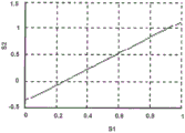
Fig. 17B is a diagram illustrating a linear transfer function y ═ x by the techniques described in this disclosure modeled with Scale2 ═ 1 and Offset2 ═ 0.
Fig. 17C is a diagram illustrating a linear transfer function modeled with scale2 ═ 1.5 and Offset ═ 0.25 by the techniques described in this disclosure.
FIG. 18 is a conceptual diagram illustrating an example of performing color conversion after applying a transfer function and before the post-processing techniques described in this disclosure.
FIG. 19 is a conceptual diagram illustrating an example of performing a reverse color conversion after the reverse post-processing technique described in this disclosure and before applying a reverse transfer function.
Fig. 20A is a diagram illustrating a post-process of clipping the histogram of S2 to a certain range.
Fig. 20B is another diagram illustrating the post-processing of clipping the histogram of S2 to a certain range.
Fig. 20C is another diagram illustrating the post-processing of clipping the histogram of S2 to a certain range.
21A and 21B are diagrams illustrating histograms of codewords after the post-processing techniques described in this disclosure with tail handling.
FIG. 22 is a conceptual diagram illustrating another example of a content adaptive HDR pipeline (encoder side) with a static TF.
FIG. 23 is a conceptual diagram illustrating another example of a content adaptive HDR pipeline (decoder side) with static TF.
Fig. 24 is a diagram illustrating a histogram with two reserved coded treatment color values.
FIGS. 25A and 25B are diagrams illustrating parameter adaptation functions implemented by the techniques described in this disclosure.
Fig. 26A, 26B, and 26C are diagrams illustrating post-processing in the case where a piece-by-piece linear transfer function implemented with the technique described in the present invention is applied to an input signal and the effect of the post-processing on the histogram of the output signal.
FIG. 27 illustrates, as an example, a mixed logarithmic gamma transfer function and a range of potential targets.
Figure 28 illustrates that the slope of the parabola around the corner is an adjustable transfer function.
Fig. 29 is a flow diagram illustrating an example method of video processing in a content adaptive High Dynamic Range (HDR) system.
Fig. 30 is a flow diagram illustrating another example method of video processing in a content adaptive High Dynamic Range (HDR) system.
Detailed Description
The present invention relates to the field of coding video signals with a High Dynamic Range (HDR) and a Wide Color Gamut (WCG) representation. More particularly, the techniques of this disclosure include signaling and operations applied to video data in certain color spaces to enable more efficient compression of HDR and WCG video data. The proposed techniques may improve compression efficiency of hybrid video coding systems (e.g., HEVC-based video coders) for coding HDR and WCG video data.
Video coding standards, including hybrid video coding standards, include ITU-T H.261, ISO/IEC MPEG-1Visual, ITU-T H.262, or ISO/IEC MPEG-2Visual, ITU-T H.263, ISO/IEC MPEG-4Visual, and ITU-T H.264 (also known as ISO/IEC MPEG-4AVC), including Scalable Video Coding (SVC) and multi-view video coding (MVC) extensions thereof. The design of a new video coding standard, namely HEVC, has been finalized by the joint collaboration group on video coding (JCT-VC) of the ITU-T Video Coding Experts Group (VCEG) and the ISO/IEC Motion Picture Experts Group (MPEG). HEVC draft specification "High Efficiency Video Coding (HEVC) text specification draft 10(for FDIS and last call) (High efficiency video coding (HEVC) text specification draft 10(for FDIS) by Bross et al, referred to as HEVC working draft 10(WD10) (Bross) et al&Last Call)) "(ITU-T SG16WP3 with the Joint collaboration team on video coding (JCT-VC) of ISO/IEC JTC1/SC29/WG 11), conference 12: rinderella Switzerland, 1 month, 14 days to 23 days 2013, JCTVC-L1003v34) may be selected fromhttp://phenix.int-evry.fr/jct/doc_end_user/documents/12_Geneva/ wg11/JCTVC-L1003-v34.zipAnd (4) obtaining. The finalized HEVC standard is referred to as HEVC version 1.
King (Wang) et al's Defect Report "High Efficiency Video Coding (HEVC) Defect Report" (Joint collaborative team on video coding (JCT-VC) of ITU-T SG16WP3 and ISO/IEC JTC1/SC29/WG 11), conference No. 14: Vienna, Austria, 7.25.2013 to 8.2.1003.v. 1) can be selected from JCT-VChttp://phenix.int-evry.fr/jct/doc_end_user/documents/14_ Vienna/wg11/JCTVC-N1003-v1.zipAnd (4) obtaining. The HEVC standard document with a fixed plan is published as ITU-T H.265 in 2013 at 4 monthsColumn H: audiovisual and multimedia systems, audiovisual service infrastructure-coding of mobile video, high efficiency video coding (telecommunication standardization sector of the International Telecommunication Union (ITU)), and another version published in 10 months 2014.
FIG. 1 is a block diagram illustrating an example video encoding and decoding system 10 that may utilize techniques of this disclosure. As shown in fig. 1, system 10 includes a source device 12 that provides encoded video data to be later decoded by a destination device 14. In particular, source device 12 provides video data to destination device 14 via computer-readable medium 16. Source device 12 and destination device 14 may comprise any of a wide range of devices, including desktop computers, notebook (i.e., laptop) computers, tablet computers, set-top boxes, telephone handsets (e.g., so-called "smart" phones), so-called "smart" tablets, televisions, cameras, display devices, digital media players, video game consoles, video streaming devices, or the like. In some cases, source device 12 and destination device 14 may be equipped for wireless communication.
In some examples, the encoded data may be output from output interface 22 to a storage device. Similarly, encoded data may be accessed from a storage device through an input interface. The storage device may include any of a variety of distributed or locally accessed data storage media, such as a hard drive, Blu-ray disc, DVD, CD-ROM, flash memory, volatile or non-volatile memory, or any other suitable digital storage medium for storing encoded video data. In another example, the storage device may correspond to a file server or another intermediate storage device that may store the encoded video generated by source device 12. Destination device 14 may access the stored video data from the storage device via streaming or download. The file server may be any type of server capable of storing encoded video data and transmitting that encoded video data to destination device 14. Example file servers include web servers (e.g., for a website), FTP servers, Network Attached Storage (NAS) devices, or local disk drives. Destination device 14 may access the encoded video data over any standard data connection, including an internet connection. Such a data connection may include a wireless channel (e.g., a Wi-Fi connection), a wired connection (e.g., DSL, cable modem, etc.), or a combination of both suitable for accessing encoded video data stored on a file server. The transmission of the encoded video data from the storage device may be a streaming transmission, a download transmission, or a combination thereof.
The techniques of this disclosure are not necessarily limited to wireless applications or settings. The techniques may be applicable to video coding in support of any of a variety of multimedia applications, such as over-the-air television broadcasts, cable television transmissions, satellite television transmissions, internet streaming video transmissions (e.g., dynamic adaptive streaming over HTTP (DASH)), digital video encoded onto a data storage medium, decoding of digital video stored on a data storage medium, or other applications. In some examples, system 10 may be configured to support one-way or two-way video transmission to support applications (e.g., video streaming, video playback, video broadcasting, and/or video telephony).
In the example of fig. 1, source device 12 includes video source 18, video encoding unit 21 (which includes video preprocessor 19 and video encoder 20), and output interface 22. Destination device 14 includes an input interface 28, a video decoding unit 29, which includes a video decoder 30 and a video post-processor 31, and a display device 32. In accordance with this disclosure, video pre-processor 19 and video post-processor 31 may be configured to apply the example techniques described in this disclosure. For example, video pre-processor 19 and video post-processor 31 may include static transfer function units configured to apply static transfer functions, also with pre-processing and post-processing units that may adapt signal characteristics.
In other examples, the source device and destination device may include other components or arrangements. For example, source device 12 may receive video data from an external video source 18, such as an external video camera. Likewise, destination device 14 may interface with an external display device, rather than including an integrated display device.
The system 10 illustrated in fig. 1 is merely one example. The techniques for processing video data may be performed by any digital video encoding and/or decoding device. Although the techniques of this disclosure are generally performed by a video encoding device, the techniques may also be performed by a video encoder/decoder (commonly referred to as a "CODEC"). For ease of description, this disclosure is described with reference to video pre-processor 19 and video post-processor 31 that pre-form the example techniques described in this disclosure in a respective one of source device 12 and destination device 14. Source device 12 and destination device 14 are merely examples of such coding devices, where source device 12 generates coded video data for transmission to destination device 14. In some examples, devices 12, 14 may operate in a substantially symmetric manner such that each of devices 12, 14 includes video encoding and decoding components. Thus, system 10 may support one-way or two-way video propagation between video devices 12, 14 for, for example, video streaming, video playback, video broadcasting, or video telephony.
Computer-readable medium 16 may include transitory media such as a wireless broadcast or a wired network transmission, or storage media (i.e., non-transitory storage media) such as a hard disk, flash drive, compact disc, digital video disc, blu-ray disc, or other computer-readable media. In some examples, a network server (not shown) may receive encoded video data from source device 12 and provide the encoded video data to destination device 14, e.g., via a network transmission. Similarly, a computing device of a media generation facility (e.g., a disc stamping facility) may receive encoded video data from source device 12 and generate a disc containing the encoded video data. Thus, in various examples, it may be appreciated that computer-readable medium 16 includes one or more computer-readable media in various forms.
As illustrated, video preprocessor 19 receives video data from video source 18. Video preprocessor 19 may be configured to process the video data to convert it into a form suitable for encoding by video encoder 20. For example, video preprocessor 19 may perform mobile dynamic range compression (e.g., using a non-linear transfer function), color conversion to a tighter or robust color space, and/or conversion of floating point to integer representations. Video encoder 20 may perform video encoding on the video data output by video pre-processor 19. Video decoder 30 may perform the inverse operations of video encoder 20 to decode the video data, and video post-processor 31 may perform the inverse operations of video pre-processor 19 to convert the video data into a form suitable for display. For example, video post-processor 31 may perform the inverse operations of integer to floating point conversion, color conversion from a compact or robust color space, and/or dynamic range compression to generate video data suitable for a display.
Video encoding unit 21 and video decoding unit 29 may each be implemented as any of a variety of fixed-function and programmable circuits, such as one or more microprocessors, Digital Signal Processors (DSPs), Application Specific Integrated Circuits (ASICs), Field Programmable Gate Arrays (FPGAs), discrete logic, software, hardware, firmware or any combinations thereof. When the techniques are implemented in part in software, a device may store instructions for the software in a suitable non-transitory computer-readable medium and execute the instructions in hardware using one or more processors to perform the techniques of this disclosure. Each of video encoding unit 21 and video decoding unit 29 may be included in one or more encoders or decoders, either of which may be integrated as part of a combined encoder/decoder (CODEC) in the respective device.
Although video pre-processor 19 and video encoder 20 are illustrated as separate units within video encoding unit 21, and video post-processor 31 and video decoder 30 are illustrated as separate units within video decoding unit 29, the techniques described in this disclosure are not so limited. Video preprocessor 19 and video encoder 20 may be formed as a common device (e.g., the same integrated circuit or housed within the same chip or chip package). Similarly, the video post-processor 31 and the video decoder 30 may be formed as a common device (e.g., the same integrated circuit or housed within the same chip or chip package).
In some examples, video encoder 20 and video decoder 30 operate according to a video compression standard such as: ISO/IEC MPEG-4Visual and ITU-T H.264 (also known as ISO/IEC MPEG-4AVC), including its Scalable Video Coding (SVC) extensions, Multiview Video Coding (MVC) extensions, and MVC-based three-dimensional video (3DV) extensions. In some cases, any bitstream that adheres to MVC-based 3DV always contains sub-bitstreams that are consistent with an MVC profile (e.g., a stereoscopic high profile). Furthermore, there is a continuing effort to produce the 3DV coding extension of H.264/AVC, i.e., AVC-based 3 DV. Other examples of video coding standards include ITU-T H.261, ISO/IEC MPEG-1Visual, ITU-T H.262, or ISO/IEC MPEG-2Visual, ITU-T H.263, ISO/IEC MPEG-4Visual, and ITU-T H.264, ISO/IEC Visual. In other examples, video encoder 20 and video decoder 30 may be configured to operate according to the ITU-T h.265, HEVC standard.
In HEVC and other video coding standards, a video sequence typically includes a series of pictures. Pictures may also be referred to as "frames". A picture may include a representation SL、SCbAnd SCrThree sample arrays. SLIs a two-dimensional array (i.e., block) of luma samples. SCbIs a two-dimensional array of Cb chroma samples. SCrIs a two-dimensional array of Cr chroma samples. Chroma samples may also be referred to herein as "chroma" samples. In other cases, a picture may be monochrome and may include only an array of luma samples.
This disclosure may use the terms "video unit" or "video block" to refer to one or more blocks of samples, and syntax structures for coding samples of the one or more blocks of samples. Example types of video units may include CTUs, CUs, PUs, Transform Units (TUs) in HEVC, or macroblocks, macroblock partitions, and so forth in other video coding standards.
After video encoder 20 generates the predictive luma block, the predictive Cb block, and the predictive Cr block for one or more PUs of the CU, video encoder 20 may generate the luma residual block for the CU. Each sample in the luma residual block of the CU indicates a difference between luma samples in one of the predictive luma blocks of the CU and corresponding samples in the original luma coding block of the CU. In addition, video encoder 20 may generate Cb residual blocks for the CU. Each sample in the Cb residual block of the CU may indicate a difference between the Cb sample in one of the predictive Cb blocks of the CU and the corresponding sample in the original Cb coding block of the CU. Video encoder 20 may also generate a Cr residual block for the CU. Each sample in the Cr residual block of the CU may indicate a difference between a Cr sample in one of the predictive Cr blocks of the CU and a corresponding sample in the original Cr coding block of the CU.
Furthermore, video encoder 20 may use quadtree partitioning to decompose the luma, Cb, and Cr residual blocks of the CU into one or more luma, Cb, and Cr transform blocks. The transform block may be a rectangular block of samples to which the same transform is applied. A Transform Unit (TU) of a CU may include a transform block of luma samples, two corresponding transform blocks of chroma samples, and syntax structures for transforming the transform block samples. In a monochrome picture or a picture with three separate color planes, a TU may comprise a single transform block, and syntax structures used to transform the transform block samples. Thus, each TU of a CU may be associated with a luma transform block, a Cb transform block, and a Cr transform block. A luma transform block associated with a TU may be a sub-block of a luma residual block of a CU. The Cb transform block may be a sub-block of a Cb residual block of the CU. The Cr transform block may be a sub-block of a Cr residual block of the CU.
After generating the coefficient blocks (e.g., luma coefficient blocks, Cb coefficient blocks, or Cr coefficient blocks), video encoder 20 may quantize the coefficient blocks. Quantization generally refers to the process by which transform coefficients are quantized to possibly reduce the amount of data used to represent the transform coefficients, providing further compression. Furthermore, video encoder 20 may inverse quantize the transform coefficients and apply an inverse transform to the transform coefficients in order to reconstruct the transform blocks of the TUs of the CU of the picture. Video encoder 20 may reconstruct the coding blocks of the CU using the reconstructed transform blocks of the TUs of the CU and the predictive blocks of the PUs of the CU. By reconstructing the coding blocks of each CU of a picture, video encoder 20 may reconstruct the picture. Video encoder 20 may store the reconstructed pictures in a Decoded Picture Buffer (DPB). Video encoder 20 may use the reconstructed pictures in the DPB for inter-prediction and intra-prediction.
After video encoder 20 quantizes the coefficient block, video encoder 20 may entropy encode syntax elements indicating the quantized transform coefficients. For example, video encoder 20 may perform Context Adaptive Binary Arithmetic Coding (CABAC) on syntax elements that indicate quantized transform coefficients. Video encoder 20 may output the entropy-encoded syntax elements in a bitstream.
Different types of NAL units may encapsulate different types of RBSPs. For example, a first type of NAL unit may encapsulate an RBSP of a Picture Parameter Set (PPS), a second type of NAL unit may encapsulate an RBSP of a coded slice, a third type of NAL unit may encapsulate an RBSP that complements enhancement information (SEI), and so on. A PPS is a syntax structure that may contain syntax elements applicable to zero or more completely coded pictures. NAL units that encapsulate RBSPs for video coding data (as opposed to RBSPs for parameter sets and SEI messages) may be referred to as Video Coding Layer (VCL) NAL units. NAL units that encapsulate a coded slice may be referred to herein as coded slice NAL units. An RBSP for a coded slice may include a slice header and slice data.
In addition, video decoder 30 may inverse quantize coefficient blocks associated with TUs of the current CU. Video decoder 30 may perform an inverse transform on the coefficient blocks to reconstruct the transform blocks associated with the TUs of the current CU. By adding samples of predictive sample blocks for PUs of the current CU to corresponding samples of transform blocks for TUs of the current CU, video decoder 30 may reconstruct coding blocks of the current CU. By reconstructing the coding blocks of each CU of a picture, video decoder 30 may reconstruct the picture. Video decoder 30 may store the decoded pictures in a decoded picture buffer for output and/or for decoding other pictures.
Next generation video applications are expected to operate on video data representing captured scenes in HDR (high dynamic range) and WCG (wide color gamut). The parameters of dynamic range and color gamut utilized are two independent attributes of video content, and their specifications for the purpose of digital television and multimedia services are defined by several international standards. For example, ITU-R Rec.709 defines the parameters of HDTV (high definition television), such as Standard Dynamic Range (SDR) and Standard color gamut, and ITU-R Rec.2020 specifies the UHDTV (ultra high definition television) parameters, such as HDR and WCG. There are also other Standards Development Organization (SDO) documents that specify dynamic range and gamut attributes in other systems, for example the P3 gamut is defined in SMPTE-231-2 (society of motion picture and television engineers) and some parameters of HDR are defined in stmpt-2084. A brief description of the dynamic range and color gamut of video data is provided below.
Dynamic range is typically defined as the ratio between the minimum and maximum luminance of a video signal. The dynamic range can also be measured in terms of 'f-stops', where one f-stop corresponds to a doubling of the signal dynamic range. In the definition of MPEG, HDR content is such content characterized by luminance variations greater than 16 f-stops. In some conditions, a scale between 10 and 16 f-stops is considered an intermediate dynamic range, but may be considered HDR in other definitions. In some examples, the HDR video content may be any video content having a higher dynamic range than conventionally used standard dynamic range-enabled video content (e.g., video content as specified by ITU-R rec.bt.709). At the same time, the Human Visual System (HVS) is able to perceive a much larger dynamic range. However, the HVS includes an adaptive mechanism to narrow the so-called simultaneous range. The visualization of the dynamic range and HVS dynamic range provided by the SDR of the HDTV, the expected HDR of the UHDTV is shown in figure 2.
Current video applications and services are governed by rec.709 and provide SDR, typically supporting a luminance (or brightness) range of about 0.1 to 100 candelas per m2 (often referred to as "nit"), resulting in less than 10 f-stops. Next generation video services are expected to provide dynamic range up to 16 f-stops. Although detailed specifications are currently under development, some initial parameters have been specified in SMPTE-2084 and rec.2020.
Another aspect of a more realistic video experience beyond HDR is the color dimension, which is conventionally defined by the color gamut. Fig. 3 is a conceptual diagram showing the SDR color gamut (triangles based on bt.709 red, green, and blue primaries) and the wider color gamut of UHDTV (triangles based on bt.2020 red, green, and blue primaries). Fig. 3 also depicts a so-called spectral trajectory (delimited by a tongue-shaped zone) which represents the boundaries of the natural color. As illustrated by fig. 3, the shift from the bt.709 primary color to the bt.2020 primary color is intended to provide approximately 70% more color for UHDTV service. D65 specifies the white color of a given specification (e.g., the bt.709 and/or bt.2020 specifications).
Several examples of color gamut specifications are shown in table 1.
TABLE 1 color gamut parameters

As can be seen in table 1, the gamut may be defined by the X and Y values of the white point and by the X and Y values of the primary colors (e.g., red (R), green (G), and blue (B)). The X and Y values represent the chromaticity (X) and luminance (Y) of a color, as defined by the CIE 1931 color space. The CIE 1931 color space defines the connection between pure colors (e.g., in terms of wavelength) and how the human eye perceives such colors.
HDR/WCG are typically acquired and stored in a 4:4:4 chroma format and an extremely wide color space (e.g., CIE 1931XYZ color space) at very high precision per component (even floating point). This representation targets high precision and is mathematically (almost) lossless. However, this format feature may include much redundancy and is not optimal for compression purposes. Lower accuracy formats with HVS-based assumptions are typically used for current advanced technology video applications.
For compression purposes, a typical video data format conversion consists of three main processes, as shown in fig. 4. The techniques of fig. 4 may be performed by video preprocessor 19. The linear RGB data 110 may be HDR/WCG video data and may be stored in floating point representation. The linear RGB data 110 may be compressed using a nonlinear Transfer Function (TF) for dynamic range compression. For example, video preprocessor 19 may include a Transfer Function (TF) unit 112 configured to use a nonlinear transfer function for dynamic range compression.
The output of the TF unit 112 may be a set of codewords, where each codeword represents a range of color values (e.g., illumination levels). Dynamic range compression means that the dynamic range of the linear RGB data 110 may be a first dynamic range (e.g., a human visual range as illustrated in fig. 2). The dynamic range of the resulting codeword may be a second dynamic range (e.g., an HDR display range as illustrated in fig. 2). Thus, the codeword captures a smaller dynamic range than the linear RGB data 110, and thus, the TF unit 112 performs dynamic range compression.
As described in more detail, the technology may scale and offset the linear RGB data 110 received by the TF unit 112 and/or scale and offset the codewords output by the TF unit 112 to better utilize the codeword space. The TF unit 112 may compress the linear RGB data 110 (or scaled and shifted RGB data) using any number of non-linear transfer functions (e.g., PQ (perceptual quantizer) TF as defined in SMPTE-2084).
In some examples, color conversion unit 114 converts the compressed data into a tighter or more robust color space that is more suitable for compression by video encoder 20 (e.g., into a YUV or YCrCb color space via a color conversion unit). As described in more detail, in some examples, the techniques may scale and offset the codeword output by the TF unit 112 application TF before the color conversion unit 114 performs the color conversion. Color conversion unit 114 may receive these scaled and offset codewords. In some examples, some scaled and offset codewords may be greater than or less than respective thresholds; for these codewords, the techniques may assign respective set codewords.
This data is then quantized using floating point to integer representation conversion (e.g., via quantization unit 116) to generate video data (e.g., HDR data 118) that is transmitted to video encoder 20 for encoding. In this example, the HDR data 118 is in an integer representation. HDR data 118 may now be in a format more suitable for compression by video encoder 20. It should be understood that the order of the processes depicted in fig. 4 is given as an example, and may be changed in other applications. For example, the TF process may be preceded by color conversion. In addition, video preprocessor 19 may apply more processing (e.g., spatial subsampling) to the color components.
Thus, in fig. 4, the high dynamic range of the input RGB data 110 in linear and floating point representations is compressed by a non-linear transfer function utilized by the TF unit 112 (e.g., PQ TF as defined in SMPTE-2084), then converted to a target color space more suitable for compression (e.g., by the color conversion unit 114) (e.g., YCbCr), and then quantized (e.g., by the quantization unit 116) to achieve an integer representation. The order of these elements is given as an example and may be changed in real world applications, e.g., the TF module (e.g., TF unit 112) may be preceded by a color conversion. Additional processing such spatial subsampling may be applied to the color components before TF unit 112 applies the transfer function.
The inverse conversion at the decoder side is depicted in fig. 5. The techniques of fig. 5 may be performed by video post-processor 31. For example, video post-processor 31 receives video data (e.g., HDR data 120) from video decoder 30 and inverse quantization unit 122 may inverse quantize the data; the reverse color conversion unit 124 performs reverse color conversion; and the inverse nonlinear transfer function unit 126 performs an inverse nonlinear transfer to generate linear RGB data 128.
The reverse color conversion process performed by reverse color conversion unit 124 may be the reverse process of the color conversion process performed by color conversion unit 114. For example, inverse color conversion unit 124 may convert HDR data from the YCrCb format back to the RGB format. The inverse transfer function unit 126 may apply an inverse transfer function to the data to add back the dynamic range compressed by the TF unit 112 to reconstruct the linear RGB data 128.
In the example techniques described in this disclosure, video post-processor 31 may apply inverse post-processing before inverse transfer function unit 126 executes the inverse transfer function; and video post-processor 31 may apply inverse pre-processing after inverse transfer function unit 126 performs the inverse transfer function. For example, as described above, in some examples, video pre-processor 19 may apply pre-processing (e.g., scaling and offsetting) before TF unit 112 and may apply post-processing (e.g., scaling and offsetting) after TF unit 112. To compensate for pre-processing and post-processing, video post-processor 31 may apply inverse post-processing before inverse TF unit 126 performs the inverse transfer function and apply inverse pre-processing after inverse TF unit 126 performs the inverse transfer function. Applying both pre-and post-processing and both inverse post-and inverse pre-processing is optional. In some examples, video pre-processor 19 may apply one, but not both, of pre-processing and post-processing, and for such examples video post-processor 31 may apply the inverse of the processing applied by video pre-processor 19.
The example video pre-processor 19 illustrated in fig. 4 is described in further detail, with the understanding that the example video post-processor 31 illustrated in fig. 5 generally performs reciprocal operations. The transfer function is applied to the data (e.g., HDR/WCG RGB video data) to compress its dynamic range and make it possible to represent the data by a limited number of bits. These limited number of bits representing data are referred to as codewords. This function is typically a one-dimensional (1D) nonlinear function that reflects the inverse of the electro-optic transfer function (EOTF) of the end-user display as specified in rec.709 for SDR, or approximates the HVS perception of luminance change for the PQ TF specified in SMPTE-2084 for HDR. The inverse of the OETF (e.g. as performed by the video post-processor 31) is the EOTF (electro-optical transfer function), which maps the code levels back to luma. Fig. 6 shows several examples of non-linear TFs. These transfer functions may also be applied separately to each R, G and B component.
In the context of the present invention, the term "signal value" or "color value" may be used to describe the brightness level of a value corresponding to a particular color component (e.g., R, G, B or Y) of an image element. The signal values typically represent linear light levels (lightness values). The terms "code level", "digital code value" or "codeword" may refer to a digital representation of an image signal value. Typically, this digital representation represents a non-linear signal value. The EOTF represents the relationship between the value of a non-linear signal provided to a display device (e.g., display device 32) and the value of a linear color generated by the display device.
The specification of ST2084 defines the EOTF application as follows. TF was applied to normalize the linear R, G, B values, which resulted in a non-linear representation of R ' G ' B '. ST2084 is standardized by the NORM 10000 definition, which correlates to a peak brightness of 10000 nits (candles/square meter).
○R'=PQ_TF(max(0,min(R/NORM,1)))
(1)
○G'=PQ_TF(max(0,min(G/NORM,1)))
(1)
○B'=PQ_TF(max(0,min(B/NORM,1)))
Wherein


PQ EOTF is visualized in fig. 7 by normalized input values (linear color values) to the range 0 … 1 on the x-axis and normalized output values (non-linear color values) on the y-axis. As can be seen from the graph in fig. 7, 1 percent of the dynamic range of the input signal (low illumination) is converted into 50% of the dynamic range of the output signal.
There are a limited number of codewords that can be used to represent an input linear color value. Fig. 7 illustrates that for PQ EOTF, approximately 50% of the available codewords are dedicated to low illumination input signals, such that fewer available codewords are used for higher illumination input signals. Thus, slight changes to the relatively high illumination input signal may not be captured because there are insufficient codewords to represent these slight changes. However, there may be an unnecessarily large number of available codewords for the low illumination input signal, meaning that even very slight changes of the relatively low illumination input signal may be represented by different codewords. Thus, there may be a larger distribution of available codewords for low illumination input signals and a relatively low distribution of available codewords for high illumination input signals.
Typically, EOTF is defined as a function with floating point accuracy. Thus, if an inverse TF (i.e. the so-called OETF) is applied, no error is introduced to the signal provided with this non-linearity. The inverse TF (OETF) specified in ST2084 is defined as the invertsepPQ function:
○R=10000*inversePQ_TF(R')
○G=10000*inversePQ_TF(G')
(2)
○B=10000*inversePQ_TF(B')
wherein


Applying EOTF and OETF in sequence provides a perfect reconstruction with no errors with floating point accuracy. However, this representation is not optimal for streaming or broadcast services. A tighter representation of non-linear R ' G ' B ' data with fixed bit accuracy is described below. It should be noted that EOTF and OETF are the subject of current very active research, and the TF utilized in some HDR video coding systems may be different from ST 2084.
Other transfer functions are also under consideration for HDR. Examples include phillips (Philips) TF or BBC hybrid "log gamma" TF. The BBC hybrid "logarithmic gamma" TF is based on the Rec 709TF for SDR traceback compatibility. To extend the dynamic range, the BBC hybrid adds a third part to the Rec 709 curve at higher input brightness. The new part of the curve is a logarithmic function.
OETF defined in Rec 709 is:

wherein L is the lightness of the image, and L is more than or equal to 0 and less than or equal to 1; and V is the corresponding electrical signal. In Rec 2020, the same equation is specified as:

where E is a voltage normalized by the reference white level and proportional to the implicit light intensity to be detected by the reference camera color channel R, G, B. E' is the resulting nonlinear signal.
For a 10-bit system, α is 1.099 and β is 0.018
For a 12-bit system, α is 1.0993 and β is 0.0181
Although not explicitly stated, α and β are solutions of the following simultaneous equations:
4.5β=αβ0.45-(α-1)
4.5=0.45αβ-0.55
the first equation is an average of the values of the linear function and the gamma function when E ═ β, and the second equation is the gradient of the two functions also when E ═ β.
Additional parts in the hybrid "logarithmic gamma" are shown below and fig. 27 illustrates the OETF. For example, fig. 27 shows a hybrid logarithmic gamma transfer function and a potential target range as an example.

In fig. 27, the corresponding curves are labeled by A, B, C, D and E to match the corresponding legend in the bottom right box of the graph. Specifically, A corresponds to 10-bit PQ-EOTF, B corresponds to 8-bit BT.709EOTF, C corresponds to 10-bit BT.709EOTF, D corresponds to 10-bit BBC mixed logarithmic gamma EOTF, and E corresponds to 12-bit PQ-EOTF.
Figure 28 illustrates that the slope of the parabola around the corner is an adjustable transfer function. FIG. 28 is illustrated merely as one example with a slope adjustment example of 5000[ candles/square meter ]. However, other examples of transfer functions with adjustable slopes are possible.
RGB data is typically used as input because it is generated by an image capture sensor. However, this color space has high redundancy among its components and is not optimal for a compact representation. To achieve a tighter and more robust representation, the RGB components are typically converted to a less relevant color space (e.g., YCbCr) that is more suitable for compression (i.e., a color transform is performed). This color space separates the luminance in the form of brightness and the color information in the different uncorrelated components.
For modern video coding systems, the commonly used color space is YCbCr, as specified in ITU-R BT.709 or ITU-R RBT.709. The YCbCr color space in the bt.709 standard specifies the following conversion process from R 'G' B 'to Y' CbCr (non-constant lightness representation):
○Y'=0.2126*R'+0.7152*G'+0.0722*B'
(3)


the above process can also be implemented using the following approximate transformation that avoids division of the Cb and Cr components:
○Y'=0.212600*R'+0.715200*G'+0.072200*B'
○Cb=-0.114572*R'-0.385428*G'+0.500000*B'
(4)
○Cr=0.500000*R'-0.454153*G'-0.045847*B'
the ITU-R bt.2020 standard specifies the following conversion process from R 'G' B 'to Y' CbCr (non-constant lightness representation):
○Y'=0.2627*R'+0.6780*G'+0.0593*B'


the above process can also be implemented using the following approximate transformation that avoids division of the Cb and Cr components:
○Y'=0.262700*R'+0.678000*G'+0.059300*B'
○Cb=-0.139630*R'-0.360370*G'+0.500000*B'
(6)
○Cr=0.500000*R'-0.459786*G'-0.040214*B'
it should be noted that both color spaces remain standardized. Thus, for input values normalized to the 0 … 1 range, the resulting values would map to the range 0 … 1. In general, color conversion implemented with floating point accuracy provides perfect reconstruction, so this process is lossless.
For quantization and/or fixed-point conversion, the processing stages described above are typically implemented in a floating-point accuracy representation, so they can be considered lossless. However, for most consumer electronics applications, this type of accuracy can be considered redundant and expensive. For such services, the input data in the target color space is converted to a target bit depth fixed-point accuracy. Some studies show that 10 to 12 bits of accuracy combined with PQ TF is sufficient to provide HDR data with 16 f-stops with less than Just-resolvable Difference (Just-Noticeable Difference). Data represented with 10 bit accuracy can be further decoded with most current state-of-the-art video coding solutions. This conversion process includes signal quantization and is a lossy coding element, and is a source of inaccuracy introduced to the converted data.
An example of such quantization applied to codewords in the target color space (YCbCr in this example) is shown below. The input values YCbCr, expressed in floating point accuracy, are converted into signals of BitDepthC with fixed bit depth BitDepthY of the Y value and chrominance values (Cb, Cr).
○DY′=Clip1Y(Round((1<<(BitDepthY-8))*(219*Y′+16)))
○DCb=Clip1C(Round((1<<(BitDepthC-8))*(224*Cb+128)))
(7)
○DCr=Clip1C(Round((1<<(BitDepthC-8))*(224*Cr+128)))
Wherein
Round(x)=Sign(x)*Floor(Abs(x)+0.5)
If x <0, sign (x) is-1; if x is 0, sign (x) is 0; if x >0, then sign (x) 1
Floor (x) maximum integer less than or equal to x
If x > -0, then abs (x) ═ x; if x <0, then abs (x) ═ x
Clip1Y(x)=Clip3(0,(1<<BitDepthY)-1,x)
Clip1C(x)=Clip3(0,(1<<BitDepthC)-1,x)
If z < x, then Clip3(x, y, z) ═ x; if z > y, then Clip3(x, y, z) ═ y; otherwise, Clip3(x, y, z) ═ z
Some techniques may not be well suited for HDR and WCG video data. Most of the currently publicly available EOTFs (e.g., PH, philips, and BBC) for use in HDR video systems are static, content-independent 1D transfer functions that are applied independently to the R, G and B components and do not take into account HDR video spatio-temporal statistics or regional brightness levels. With such EOTF utilization in an HDR video coding system, this approach would result in non-optimal bit allocation for the provided visual quality of the HDR video content.
A second problem with currently utilized HDR processing pipelines is the static conversion of non-linear codewords in the target color space from floating point accuracy representation to representation. Usually, HDR content where the codeword space is fixed and varies in time and space will not get an optimal representation. More details on these two issues are provided below.
Regarding the non-optimal of static 1D EOTF, the EOTF defined in ST2084 specifies a static, content-independent 1D transfer function, denoted PQ TF, which is presumably based on the perceptual sensitivity of the Human Visual System (HVS) at a certain level of brightness (a few candelas per square meter). While most studies define HVS perceptual sensitivity to luminance in candelas per square meter, PQ TF is independently applied to each of color values R, G and B, as in equation 1 (e.g., to determine R ', G ', and B '); and the luminance intensity of this RGB pixel is not utilized. This leads to possible inaccuracies in the PQ TF when approximating HVS sensitivity to non-linearity of the resulting R 'G' B ', e.g., a combination of R' G 'B' color values may result in different levels of brightness that would otherwise be associated with another PQ TF value compared to the PQ TF value applied independently to each of the R, G, B components.
Furthermore, due to this design intent, PQ TF combines HVS sensitivity in two modes, the so-called night light vision and the low-light (so-called night) vision. The latter vision comes into play when the luminance of the scene is below 0.03cd/m2 and is characterized by much higher sensitivity at the expense of reduced color perception. To achieve high sensitivity, the PQ TF utilized provides a larger number of codewords to low luma values, as reflected in fig. 7. Such codeword distribution may be optimal and will operate in night vision mode if the brightness of the picture is low HVS. For example, such a codeword distribution may be optimal if the codeword is sensitive to small changes in brightness. However, a typical HDR picture may be characterized by a bright scene and dark noisy segments that will not affect the visual quality but will greatly affect the bit rate using the current still TF due to shadowing from the nearest bright sample.
With regard to inefficient utilization of codeword space, the non-linear codewords (Y', Cb, Cr) represented in floating point accuracy and their representation (D) with a fixed number of bits as shown in equation (7) are quantizedY'、DCb、DCr) Is the primary compression tool for HDR pipelines. Typically, the dynamic range of the input signal prior to quantization is less than 1.0 and falls within the range of 0 … 1 for the Y component and-0.5 … 0.5.5 for the Cb and Cr components.
However, the actual distribution of the HDR signal varies from frame to frame, so quantization as shown in equation (7) will not provide the minimum quantization error, and can be improved by adjusting the dynamic range of the HDR signal to match the expected range equal to 1.0.
In order to solve the above-described problems, the following solutions may be considered. The EOTF may be defined as a dynamic, content adaptive transfer function having a shape that changes depending on the nature of the content (e.g., at the frame level), as illustrated in fig. 8. Fig. 8 illustrates a content adaptive HDR processing pipeline (encoder side) with an adaptive shape TF unit 112'. For example, fig. 8 illustrates another example of video preprocessor 19 that includes adaptive shape TF functions utilized by TF units.
The assembly of fig. 8 corresponds generally to the assembly of fig. 4. In the example of fig. 8, components having the same reference numerals as those of the example in fig. 4 are the same. However, in fig. 8, the adaptive TF unit 112' applies an adaptive TF, while the non-TF unit 112 applies a static TF, as illustrated in fig. 4. In this example, the manner in which the adaptive TF unit 112' performs data compression is adaptive and may vary based on the video content. Although a corresponding video post-processor 31 is not illustrated, this example video post-processor 31 will execute an adaptive inverse transfer function instead of the static inverse transfer function of inverse transfer function unit 126 of fig. 5. The video pre-processor 19 will output information indicating the parameters used by the TF unit 112' to adapt the TF. The video post-processor 31 will accordingly receive such information indicating the parameters used by the TF unit 112' to adapt the adaptive inverse transfer function.
However, this technique may require extensive signaling of parameters for transfer function adaptation as well as implementation to support such adaptation, such as storing multiple lookup tables or implementation branches. Furthermore, certain aspects of the non-optimality of PQ EOTF may be addressed via 3D transfer functions. Such approaches may be too expensive for certain implementations and signaling costs.
In this disclosure, signaling refers to outputting syntax elements or other video data for decoding or otherwise reconstructing the video data. The signaled parameters may be stored for later retrieval by the destination device 14 or may be transmitted directly to the destination device 14.
The present invention describes a content adaptive HDR video system using static fixed Transfer Functions (TF). This disclosure describes maintaining static TF in a pipeline, but adapting signal characteristics to a fixed process flow. This can be achieved by adaptively processing the signal to be processed by the TF or the signal generated by applying the TF. Some techniques may combine both of these adaptation mechanisms. At the decoder (e.g., video post-processor 31), the adaptation process (which is the inverse of the process applied at the encoder side (e.g., video pre-processor 19)) will be applied.
Fig. 9 is a conceptual diagram showing a content adaptive HDR processing pipeline (encoder side) with a fixed TF. As illustrated, video pre-processor 19 includes pre-processing unit 134 (also referred to as dynamic range adjustment (DRA1), TF unit 112, post-processing unit 138 (also referred to as DRA2), color conversion unit 114, and quantization unit 116.
In the illustrated example, video preprocessor 19 may be configured as a fixed function and programmable circuit. For example, video pre-processor 19 may include transistors, capacitors, inductors, passive and active components, Arithmetic Logic Units (ALUs), Elementary Function Units (EFUs), and the like, that collectively or separately form pre-processing unit 134, TF unit 112, post-processing unit 138, color conversion unit 114, and quantization unit 116. In some examples, video pre-processor 19 includes a programmable core that executes instructions that cause pre-processing unit 134, TF unit 112, post-processing unit 138, color conversion unit 114, and quantization unit 116 to perform their respective functions. In these examples, video data memory 132 or some other memory may store instructions that are executed by video preprocessor 19.
In fig. 9, the video data memory 132 is also illustrated for ease of understanding. For example, video data memory 132 may temporarily store video data before video preprocessor 19 receives the video data. As another example, any video data output by video preprocessor 19 may be temporarily stored in video data memory 132 (e.g., stored in video data memory prior to output to video encoder 20). Video data memory 132 may be part of video preprocessor 19 or may be external to video preprocessor 19.
The video data stored in video data memory 132 may be obtained, for example, from video source 18. The video data memory 132 may be formed from any of a variety of memory devices, such as Dynamic Random Access Memory (DRAM), including synchronous DRAM (sdram), magnetoresistive ram (mram), resistive ram (rram), or other types of memory devices. In various examples, video data memory 132 may be on-chip with other components of video preprocessor 19, or off-chip with respect to those components.
As described in more detail below, preprocessing unit 134 (e.g., DRA1) preprocesses linear RBG data 110 before static transfer function unit 112 applies the static transfer function. Part of the pre-processing includes scaling and offsetting (e.g., multiplying the input value by a factor to scale, and adding a value to offset). In some examples, pre-processing unit 134 pre-processes the video data based on the video content (e.g., the scaling factor and the offset factor are based on the video content). TF unit 112 then applies the transfer function to the scaled and offset input values to generate a plurality of codewords. In this example, TF unit 112 applies a static transfer function that compresses the dynamic range of the input values such that the generated plurality of codewords represent colors within a smaller dynamic range than the input color values (e.g., linear RGB data 110).
Post-processing unit 138 (e.g., DRA2) performs post-processing functions on the codewords generated by TF unit 112. For example, the output of the TF unit 112 may be a non-linear codeword representing a color value. Post-processing unit 138 may also scale and offset the codewords output by TF unit 112. The color conversion unit 114 performs color conversion (e.g., from RGB to YCrCb) on the output of the post-processing unit 138, and the quantization unit 116 performs quantization on the output of the color conversion unit 114.
By preprocessing the linear RGB data 110, the preprocessing unit 134 may be configured to scale and offset the linear RGB data 110 such that although the TF unit 112 applies the static transfer function, the input to the TF unit 112 is adjusted such that the output codeword of the TF unit 112 is more linear. In addition, by pre-processing the linear RGB data 110, the pre-processing unit 134 may use the video content to select scaling and offset parameters that take into account spatio-temporal statistics or regional luminance levels.
There may be various ways in which the pre-processing unit 134 may determine the scaling and offset parameters. As one example, pre-processing unit 134 may determine a histogram for each of the colors in the picture (e.g., determine a histogram for red, a histogram for green, and a histogram for blue). The histogram indicates how many pixels of a particular color have a particular illumination level. The pre-processing unit 134 may be pre-programmed with a mathematical representation of the transfer function to be applied by the TF unit 112 such that the pre-processing unit 134 may scale and shift the color values to improve the linearity of the codewords output by the TF unit 112.
The pre-processing unit 134 may normalize the histogram of the input signal over a limited span [ hist _ min … hist _ max ] within the full dynamic range [0 … 1] of the allowed codeword space of the input signal. The pre-processing unit 134 may determine scaling and offset parameters to be applied to the input signal by horizontally stretching the histogram for each of the color values and determining an offset and a scale based on the stretched histogram. For example, the equations used to determine the offset and scaling may be:
Offset1=-hist_min
Scale1=1/(hist_max-hist_min)
preprocessing unit 134 may determine Offset and scaling parameters for each of the colors using the equations of Offset1 and Scale1, and apply the Offset1 and Scale1 parameters as described in more detail to Scale and Offset the color values. There may be various other ways that pre-processing unit 134 determines the offset and scaling parameters for pre-processing, and the above equation is provided as one example.
The post-processing unit 138 may determine the offset and scaling parameters in a similar manner, but the post-processing unit 138 applies the determined offset and scaling parameters to the color codeword. For example, post-processing unit 138 may determine a histogram for each of the codewords output by TF unit 112. Post-processing unit 138 may normalize the histogram of the codeword over a limited span [ hist _ min … hist _ max ] within the full dynamic range [0 … 1] of the allowed codeword space. Post-processing unit 138 may determine the scaling and offset parameters to be applied to the codewords by stretching the histogram for each of the codewords for each of the color values and determining the offset and scaling based on the stretched histograms. For example, the equations used to determine the offset and scaling may be:
Offset1=-hist_min
Scale1=1/(hist_max-hist_min)
Although color conversion unit 114 is illustrated after post-processing unit 138, in some examples, color conversion unit 114 may first convert colors from RGB to YCrCb. The post-processing unit 138 may perform operations on the YCrCb codeword. For the luma (Y) component, the post-processing unit 138 may determine the scaling and offset values using techniques similar to those described above. Techniques for determining the scaling and offset of the chroma components are described below.
The post-processing unit 138 may determine the scaling and shifting parameters for the Cb and Cr color components based on the colorimetry of the input video signal and the target colorimetry of the output video signal. For example, consider a target (T) color container specified by primary color coordinates (xXt, yXt), where X refers to R, G, B color components:

and a native (N) gamut specified by primary color coordinates (xXn, yXn), where X refers to R, G, B color components:

the white point coordinates of the two gamuts are equal to whiteP ═ xW, yW. The DRA parameter estimation unit (e.g., post-processing unit 138) may derive the scales Cb and Cr for the Cb and Cr color components as a function of the distance between the primary color coordinates and the white point. An example of this estimate is given as follows:
rdT=sqrt((primeT(1,1)-whiteP(1,1))^2+(primeN(1,2)-whiteP(1,2))^2)
gdT=sqrt((primeT(2,1)-whiteP(1,1))^2+(primeN(2,2)-whiteP(1,2))^2)
bdT=sqrt((primeT(3,1)-whiteP(1,1))^2+(primeN(3,2)-whiteP(1,2))^2)
rdN=sqrt((primeN(1,1)-whiteP(1,1))^2+(primeN(1,2)-whiteP(1,2))^2)
gdN=sqrt((primeN(2,1)-whiteP(1,1))^2+(primeN(2,2)-whiteP(1,2))^2)
bdN=sqrt((primeN(3,1)-whiteP(1,1))^2+(primeN(3,2)-whiteP(1,2))^2)
scale Cb=bdT/bdN
scale Cr=sqrt((rdT/rdN)^2+(gdT/gdN)^2)
the Cb and Cr offset parameters for such embodiments may be set equal to 0:
offset Cb=offset Cr=0
in some examples, color conversion unit 114 may convert RGB to YCrCb before pre-processing unit 134 applies pre-processing. For such examples, pre-processing unit 134 may perform operations similar to those described above for post-processing unit 138 on the YCrCb values, but on the input color values before TF unit 112 applies the transfer function.
The signal-to-quantization noise ratio typically reflects the relationship between the maximum nominal signal strength and the quantization error (also called quantization noise): SNR ^ E (x ^2)/E (n ^2), wherein E (x ^2) is the power of the signal, and E (n ^2) is the power of the quantization noise; where ^ denotes exponential operation, E is energy and n is noise.
Multiplying the signal x with scaling parameters >1.0 will result in an increase of the signal power and thus in an improved signal to quantization noise ratio: SNR2 ═ E ((scale x) ^2)/E (n ^2) > SNR.
It is understood that in various examples, the transfer function applied by TF unit 112 is static (e.g., non-content adaptive). However, data output to the TF unit 112 may be adapted (e.g., by the pre-processing unit 134) and/or data output by the TF unit 112 may be adapted (e.g., by the post-processing unit 138). In this way, video preprocessor 19 outputs codewords representing colors within a reduced dynamic range (as compared to the dynamic range of linear RGB data 110), where the output codewords are based on video content. Thus, by adapting the input to the TF unit 112 and the output of the TF unit 112, the combination of the pre-processing unit 134, the TF unit 112 and the post-processing unit 138 functions to apply the adaptive transfer function.
Fig. 10 is a conceptual diagram showing a content adaptive HDR processing pipeline (decoder side) with a fixed TF. As illustrated, video post-processor 31 includes an inverse quantization unit 122, an inverse color conversion unit 124, an inverse post-processing unit 144, an inverse TF unit 126, and an inverse pre-processing unit 142.
In the illustrated example, the video post-processor 31 may be configured as a fixed function and programmable circuit. For example, video post-processor 31 may include transistors, capacitors, inductors, passive and active components, Arithmetic Logic Units (ALUs), Elementary Function Units (EFUs), and the like, that collectively or separately form inverse quantization unit 122, inverse color conversion unit 124, inverse post-processing unit 144, inverse TF unit 126, and inverse pre-processing unit 142. In some examples, video post-processor 31 includes a programmable core that executes instructions that cause inverse quantization unit 122, inverse color conversion unit 124, inverse post-processing unit 144, inverse TF unit 126, and inverse pre-processing unit 142 to perform their respective functions. In these examples, video data memory 140 or some other memory may store instructions that are executed by video post-processor 31.
In fig. 10, the video data memory 140 is also illustrated for ease of understanding. For example, video data memory 140 may temporarily store video data output by video post-processor 31. As another example, any video data output by video decoder 30 to video post-processor 31 may be temporarily stored in video data memory 140 (e.g., stored in video data memory prior to being received by video post-processor 31). The video data memory 140 may be part of the video post-processor 31 or may be external to the video post-processor 31.
For example, video data stored in video data memory 140 may be output to display device 32. The video data memory 140 may be formed from any of a variety of memory devices, such as Dynamic Random Access Memory (DRAM), including synchronous DRAM (sdram), magnetoresistive ram (mram), resistive ram (rram), or other types of memory devices. In various examples, video data memory 140 may be on-chip with other components of video post-processor 31, or off-chip with respect to those components.
The video post-processor 31 may be configured to perform the inverse processing of the video pre-processor 19. For example, video decoder 30 outputs decoded video data to video post-processor 31, which may be substantially similar to the video data output by video pre-processor 19 to video encoder 20. In addition, the video decoder 30 may output Adaptive Transfer Function (ATF) parameters to the video post-processor 31 to perform inverse processing of the pre-processing and post-processing performed by the video pre-processor 19.
The inverse post-processing unit 144 may perform the inverse operation of the post-processing unit 138. The inverse post-processing unit 144 receives codewords representing colors within a first dynamic range, which in this case is the same dynamic range as the output of the post-processing unit 138.
Rather than multiplying by a scaling factor as post-processing unit 138, inverse post-processing unit 144 may be divided by a scaling factor that is substantially similar to the scaling factor by which post-processing unit 138 is multiplied. If post-processing unit 138 subtracts the offset from the scaled codeword, inverse post-processing unit 144 may add the offset to the inversely scaled codeword. The output of inverse postprocessing unit 144 may be codewords that are not spread across the entire codeword space. In some examples, inverse post-processing unit 144 may receive scaling and offset parameters (e.g., scaling and offset factors) from video pre-processor 19. In some examples, the inverse post-processing unit 144 may receive information from which the inverse post-processing unit 144 determines the scaling and offset factors.
The reverse TF unit 126 performs a reverse operation of the TF unit 112. For example, TF unit 112 compresses the color values in codewords that represent a smaller dynamic range compared to the dynamic range of the color values. The inverse TF unit 126 extends the color values from the smaller dynamic range back into the larger dynamic range. The output of the inverse TF unit 126 may be linear RGB data; however, some pre-processing may need to be removed to produce the raw RGB data.
Rather than multiplying by a scaling factor as with pre-processing unit 134, inverse pre-processing unit 142 may be divided by a scaling factor that is substantially similar to the scaling factor by which pre-processing unit 134 multiplies. If pre-processing unit 134 subtracts the offset from the scaled color value, inverse pre-processing unit 142 may add the offset to the inversely scaled color value. In some examples, inverse pre-processing unit 142 may receive scaling and offset parameters (e.g., scaling and offset factors) from video pre-processor 19. In some examples, inverse pre-processing unit 142 may receive information (e.g., histogram information) from which inverse pre-processing unit 142 determines scaling and offset factors.
The output of the inverse pre-processing unit 142 may be linear RGB data 128. The linear RGB data 128 and the linear RGB data 110 should be substantially similar. The display device 32 may display linear RGB data 128.
Similar to TF unit 112, the inverse transfer function applied by inverse TF unit 126 is a static inverse transfer function (e.g., not adaptive to the video content). However, data output to inverse TF unit 126 may be adapted (e.g., by inverse post-processing unit 144) and/or data output by inverse TF unit 126 may be adapted (e.g., by inverse pre-processing unit 142). In this way, the video post-processor 31 outputs color values representing colors that are not within a reduced dynamic range (as compared to the reduced dynamic range of the output of the post-processing unit 138). Thus, by adapting the input to the inverse TF unit 126 and the output of the inverse TF unit 126, the combination of the inverse post-processing unit 144, the inverse TF unit 126, and the inverse pre-processing unit 142 functions to apply the adaptive inverse transfer function.
Although both pre-processing unit 134 and post-processing unit 138 are illustrated in FIG. 9, example techniques described in this disclosure are not so limited. In some examples, video pre-processor 19 may include pre-processing unit 134, but may not include post-processing unit 138. In some examples, video pre-processor 19 may include post-processing unit 138, but may not include pre-processing unit 134.
Thus, fig. 9 illustrates an example of a device (e.g., source device 12) for video processing in a content adaptive HDR system, where the device includes video data memory 132 and video preprocessor 19. Video preprocessor 19 includes at least one of a fixed function or a programmable circuit, or a combination of both, and is configured to receive a plurality of color values of video data (e.g., linear RGB data 110) representing colors within a first dynamic range. Video preprocessor 19 includes a TF unit 112 configured to compress color values using a static transfer function that is not adaptive to the compressed video data to generate a plurality of codewords representing compressed color values within a second dynamic range. The second dynamic range is more compact than the first dynamic range.
Furthermore, although both an inverse post-processing unit 144 and an inverse pre-processing unit 142 are illustrated in FIG. 10, example techniques described in this disclosure are not so limited. In some examples, video post-processor 31 may include inverse post-processing unit 144, but may not include inverse pre-processing unit 142 (e.g., in examples where video pre-processor 19 does not include pre-processing unit 134, although the techniques are not limited thereto). In some examples, video post-processor 31 may include inverse pre-processing unit 142, but may not include inverse post-processing unit 144 (e.g., in examples where video pre-processor 19 does not include post-processing unit 138, although the techniques are not limited thereto).
Thus, fig. 10 illustrates an example of a device (e.g., destination device 14) for video processing in a content adaptive HDR system, where the device includes video data memory 140 and video post-processor 31. The video post-processor 31 comprises at least one of a fixed function or a combination of two of programmable circuits, and is configured to receive a first plurality of codewords representing compressed color values of the video data. The compressed color values represent colors within a first dynamic range (e.g., a dynamic range substantially similar to the compressed dynamic range of the codeword output by video pre-processor 19). Video post-processor 31 includes an inverse TF unit 126 configured to decompress a second plurality of codewords based on the first plurality of codewords using an inverse static transfer function that is non-adaptive to the video data to generate decompressed color values. The decompressed color values represent colors within a second dynamic range (e.g., a dynamic range substantially similar to the linear RGB data 110). The second plurality of codewords is one of codewords from the first plurality of codewords that have been reverse post-processed (e.g., in an example that includes reverse post-processing unit 144) or the first plurality of codewords (e.g., in an example that does not include reverse post-processing unit 144).
Fig. 9 and 10 illustrate example techniques for content adaptive Dynamic Range Adjustment (DRA) to reduce artifacts generated by fixed (e.g., static) transfer functions. However, by pre-processing and/or post-processing the data received or output by TF unit 112 and by inverse post-processing and/or inverse pre-processing the data received or output by inverse TF unit 126, the example techniques may still use static transfer functions, yet still achieve a content adaptive DRA.
The present invention describes a content adaptive HDR video system using static fixed Transfer Functions (TF). Some examples are described below that may be used together or may be kept separate. For convenience, the examples are described separately with the understanding that various permutations and combinations are possible.
As described above, the techniques described in this disclosure utilize static TFs (e.g., for generating encoded video content) in the pipeline, but adapt the signal characteristics to a fixed processing flow. This may be achieved by adaptively processing the signal to be processed by the TF unit 112 (e.g., by the pre-processing unit 134) or adaptively processing the signal generated by the TF unit 112 applying the TF (e.g., by the post-processing unit 138).
In one example, pre-processing unit 134 may achieve adaptivity by linearly (scaling and offsetting) pre-processing the input linear color values before TF unit 112 applies the transfer function. In addition to or in lieu of pre-processing unit 134, post-processing unit 138 may achieve adaptivity by linearly (scaling and offset) post-processing the non-linear codewords generated by TF unit 112 applying a TF to linear color values. The inverse post-processing unit 144, the inverse TF unit 126, and the inverse pre-processing unit 142 may apply inverse operations of the post-processing unit 138, the TF unit 112, and the pre-processing unit 134, respectively.
In the example described above, the pre-processing unit 134 applies pre-processing to the linear RGB data 110. However, the techniques described in this disclosure are not so limited. RGB is one color space of HDR, which preprocessing unit 134 may perform preprocessing on. In general, pre-processing unit 134 may implement pre-processing in any color space of the HDR processing flow (e.g., in input linear RGB in the illustrated example, but other color spaces are also possible, such as the YCbCr color space) before TF unit 112 applies the transfer function.
The above example describes that post-processing unit 138 performs post-processing in an RGB color space (e.g., non-linear RGB due to the transfer function applied by TF unit 112). However, the techniques described in this disclosure are not so limited. RGB is one color space of HDR, on which post-processing unit 138 may perform post-processing. In general, post-processing unit 138 may implement post-processing in any color space of the HDR processing flow (e.g., in non-linear RGB in the illustrated example, but other color spaces are also possible, such as the YCbCr color space) after TF unit 112 applies the transfer function.
As described above, pre-processing unit 134 at the encoder side may derive and apply parameters such as Scale1 and Offset1 factors from the input or target color space (e.g., linear RGB data 110 or YCrCb if color conversion unit 114 receives linear RGB data 110 and converts colors to YCrCb values) or HDR signal properties in the supplemental color space to produce better parameter derivation, such as histogram distribution. Post-processing unit 138 may also derive and apply parameters, such as Scale2 and Offset2 factors, from the output of TF unit 112.
In some examples, video pre-processor 19 (e.g., via a controller circuit) may selectively enable use of pre-processing unit 134 and/or post-processing unit 138. Accordingly, video pre-processor 19 may output information indicating whether pre-processing unit 134 and/or post-processing unit 138 are enabled. In response, the video post-processor 31 (e.g., via a controller circuit) may selectively enable use of the inverse post-processing unit 144 and/or the inverse pre-processing unit 142.
There may be various ways in which video encoder 20 may encode and output various parameters. For example, video encoder 20 may signal the parameters and video decoder 30 may receive the parameters provided to the decoder side (e.g., video post-processor 31) via the bitstream by means of SEI (supplemental enhancement information)/VUI (video usability information), or as side information, or derived by the decoder side (e.g., by video post-processor 31) according to other identifications (e.g., input and output color spaces, utilized transfer functions, etc.).
Example techniques that may be applied in accordance with the example techniques described in this disclosure are described below. Each of these techniques may be applied separately or in any combination. Moreover, each of these techniques is described in further detail below.
In the above example, the video preprocessor 19 may signal the parameter information in various ways. As just one example, video encoder 20 includes an encoding unit (e.g., an entropy encoding unit), and the entropy encoding unit may encode the signaled parameter information. Similarly, video decoder 30 includes a decoding unit (e.g., an entropy decoding unit), and the entropy decoding unit may decode the signaled parameter information and video post-processor 31 may receive the parameter information from video decoder 30. There may be various ways in which parameter information may be signaled and received, and the techniques described in this disclosure are not limited to any particular techniques. Furthermore, as shown above, in all cases, video pre-processor 19 may not require signaling parameter information. In some examples, video post-processor 31 may derive the parameter information without having to receive the parameter information from video pre-processor 19.
The following are example implementations used for illustration purposes only and should not be viewed as limiting. For example, this disclosure describes achieving adaptivity by linearly (scaling and offsetting) preprocessing input linear color values before applying TFs (e.g., static, non-content adaptive) and/or by linearly (scaling and offsetting) post-processing non-linear codewords generated by TFs applied to linear color values. The following are several non-limiting examples of implementations of the technology.
The proposed forward ATF process flow is shown in fig. 11. In this example, linear signal component s in the input color space (e.g., RGB) is being pre-processed by pre-processing unit 134 to generate output signal s 1. TF unit 112 applies the transfer function to the value of S1 to produce output codeword S1. In the next step, the codeword of S1 is post-processed by post-processing unit 138 to produce output value S2.
Fig. 12 is a reverse process flow of the ATF process flow illustrated in fig. 11. For example, the inverse post-processing unit 144 performs inverse post-processing on the codeword S2'. Codeword S2' may be substantially similar to codeword S2. The output of the inverse post-processing by the inverse post-processing unit 144 is a codeword S1'. Codeword S1' may be similar to codeword S1. The inverse TF unit 126 receives the codeword S1', and the output of the inverse TF unit 126 is S1', which represents a color value and is similar to the color value S1. Inverse pre-processing unit 142 receives s1 'as input and outputs color value s'. The color value s' is substantially similar to the color value s.
For ease of illustration, the various processes are not illustrated in fig. 11 and 12. For example, color conversion and quantization, and their respective inverse processes, are not illustrated in fig. 11 and 12.
Example operations and algorithms executable by the pre-processing unit 134 and the inverse pre-processing unit 142 are described below. The pre-processing unit 134 is defined by the parameters Scale1 and Offset 1. The pre-processing unit 134 aims to adapt the input signal characteristics to certain properties of the transfer function applied by the TF unit 112. An example of such processing is illustrated in fig. 13A and 13B. FIG. 13A shows a histogram of the red component of an HDR signal overlaid with a PQT transfer function; it should be noted that the signals are shown in different scales for visualization purposes. A histogram of the nonlinear signal generated by the PQTF is shown in fig. 13B (e.g., if the TF unit 112 applies the PQTF without using the pre-processing unit 134).
As illustrated, with the curve of PQTF (which is the same as fig. 7), PQTF provides more codewords to low luminance samples, e.g., allowing 0 … 1% of the input dynamic range to be represented by 50% of the output dynamic range. Such a distribution may not be optimal for certain classes of signals and/or applications.
For linear pre-processing, pre-processing unit 134 may apply linear pre-processing to input signal s to achieve a preferred codeword distribution for the TF output from TF unit 112 by applying Offset1 and scaling Scale 1.
s1=Scale1*(s-Offset1)
(8)
The signal value s1 generated by equation 8 is utilized in equation 1, and the HDR processing pipeline specified in equations (3-7) is applied (e.g., by color conversion unit 114 and quantization unit 116).
At the decoder side (e.g., video post-processor 31), inverse pre-processing unit 142 applies the operations inverse to pre-processing as follows:

where the term s1' denotes the linear color value produced by the inverse TF as specified in equation 2. In other words, s1' is the output of the inverse transfer function applied by inverse TF unit 126.
The effect of such pre-processing with parameters (Scale1 ═ 0.1 and Offset1 ═ 0.0001) is shown in fig. 14. FIG. 14 results from the same inputs as illustrated in FIG. 13A. It can be seen that the codewords of the S1 signal occupy the available dynamic range more efficiently than the example illustrated in fig. 13B, and the representation of high luminance values is more accurate because they occupy a much larger dynamic range (see the stretched peaks of histogram S1 in fig. 14, compared to the histogram peaks in fig. 13B).
In some examples, the input to TF cell 112 may be a bipolar signal. The bipolar signal is intended to indicate that some values of the output of the preprocessing unit 138 are negative and others are positive. To enable a static TF to be applied even to (and an inverse static TF to be applied by inverse TF unit 126) the bipolar signal by TF unit 112, TF unit 112 may adjust the output of pre-processing unit 134 and/or adjust the output after applying the transfer function. For example, if the output of pre-processing unit 134 is negative, TF unit 126 may apply a transfer function to the absolute value of the output of pre-processing unit 134 and multiply the result by the output of a sign(s) function, where s is the output of pre-processing unit 134 and sign(s) -1 for s < 0; for s ═ 0, sign(s) ═ 0; and for s >0, sign(s) ═ 1. Thus, to enable the application of static TF, TF unit 112 may utilize a function defined by a positive value that implies some special handling of the sign of the bipolar signal for bipolar signals.
The transfer function with bipolar signal handling is described below. In some examples, the techniques may modify equation (1) to be able to handle bipolar input signals.

This technique may allow the TF unit 112 of fig. 9 to allocate a TF of a desired steepness at a desired region of the dynamic range, e.g., if a more accurate representation of the signal of a medium brightness level is desired. A visualization of this concept with the parameters scale 0.1 and offset 0.1 is shown in fig. 15A and 15B.
Thus, the inverse TF for a bipolar signal will be defined as modified equation 2:

for example, for the case where the input codeword is positive, the reverse TF unit 126 of fig. 10 may apply a reverse transfer function. For input codewords that are negative, inverse TF unit 126 may determine the absolute value of the input codeword and apply an inverse transfer function to the absolute value of the input codeword. TF unit 126 may multiply the result by the output of a sign () function, where the input to the sign () function is the codeword received by inverse TF unit 126.
Example operations and algorithms executable by the post-processing unit 138 and the inverse post-processing unit 144 are described below. The post-processing unit 138 is defined by the parameters Scale2 and Offset2 and allows for efficient utilization of the available codeword space (dynamic range) after application of the TF by the TF unit 112. Examples of such processing are described below.
The following is an example of the HDR signal after applying the TF by the TF unit 112. Fig. 16A shows a histogram of the red component of the HDR signal after applying the TF by TF unit 112. As illustrated, in this example, the histogram of the signal does not occupy the full codeword space, but instead only utilizes 60% of the codewords in practice. Neither of these representations is problematic until the signal is represented in floating point accuracy. However, unused codeword budget can be more efficiently utilized to reduce the quantization error introduced by equation 7.
The post-processing unit 138 may apply linear operations of offset and scaling to the codeword S generated after applying the TF by the TF unit 112:
S2=scale2*(S-offset2)
(12)
in some architectures, the post-processing unit 138 (FIG. 9) may clip the resulting S value to the specified dynamic range as follows:
S2=min(maxValue,max(S2,minValue))
(13)
after this processing, the signal value S2 is utilized in equation (3), and is followed by the HDR process flow specified in equations (3-7).
At the decoder side (e.g., video post-processor 31), inverse post-processing unit 144, which may apply operations inverse to post-processing, is implemented as follows:

in some architectures, the inverse post-processing unit 144 may clip the resulting S value to the specified dynamic range as follows:
S′=min(maxValue,max(S′,minValue))
(15)
where the term S2' represents a decoded non-linear color value.
The effect of such post-processing by the parameters (scale 0.8 and offset 0) is shown in fig. 16B. It can be seen that the codewords of the S2 signal occupy the available codeword space more efficiently (dynamic range) and the representation of high luminance values is more accurate because they occupy a much larger dynamic range (see the stretched peaks of histogram S2 in fig. 16B compared to the histogram peaks in fig. 16A).
In the above example, rather than applying the operation of equation (12), post-processing unit 138 may be considered to apply a second transfer function, which is a linear transfer function, rather than the non-linear transfer function applied by TF unit 112. Applying this second transfer function may be equivalent to multiplying the input codeword with Scale2 and adding Offset2, and inverse post-processing unit 144 applies the inverse of this process. Thus, in some examples, the techniques of post-processing unit 138 and inverse post-processing unit 144 (fig. 10) may be deployed via additional linear transfer function TF 2. The parameters of this additional linear transfer function TF2 may be specified via Scale2 and Offset2, for example as shown in fig. 17A-17C.
For example, fig. 17A illustrates the same transfer function behavior as fig. 7 (e.g., the static transfer function applied by TF unit 112). Fig. 17B illustrates the transfer function that post-processing unit 138 applies to the output of TF unit 112 if Scale2 is equal to 1 and Offset2 is equal to 0. Fig. 17C illustrates the transfer function that post-processing unit 138 applies to the output of TF unit 112 if Scale2 is 1.5 and Offset2 is-0.25.
The above examples describe the situation where pre-processing unit 134(DRA1) and/or post-processing unit 138(DRA2) are present, as well as corresponding inverse pre-processing unit 142 and inverse post-processing unit 144. In some examples, post-processing may be performed after color conversion (e.g., in the target color space) rather than before color conversion. For example, as illustrated in fig. 18, TF unit 112 outputs to color conversion unit 114 and post-processing unit 150 applies post-processing after color conversion. Similarly, as illustrated in fig. 19, inverse post-processing unit 152 applies inverse post-processing to the output of inverse quantization unit 122 and prior to application of color conversion by inverse color conversion unit 124. In fig. 18 and 19, the pre-processing unit 134 and the inverse pre-processing unit 142 are not illustrated for convenience, and may be included in other examples.
For some HDR systems that utilize some target color space (e.g., YCbCr of BT709 or BT 2020), and with post-processing that utilizes the same parameters for R, G and the 3 components of B, post-processing may be applied in the output color space rather than in the input RGB color space.
For example, for the YCbCr color transform, as defined in equations 3 and 5:
○Y'=a*R'+b*G'+c*B'
(16)


where the variables a, B, c, d1, and d2 are parameters of the color space, and R ', G ', B ' are nonlinear color values in the input color space after the EOTF is applied.
The post-processing defined in equations 12 and 13 is applied at the input color space, i.e., to R ', G', B ', to produce output values R2', G2', B2':

in equation 17, it is assumed that R, G is the same as the parameters of the post-processing in the B domain.
However, due to the linearity of the process defined in equations 16 and 17, post-processing can be implemented in the target color space:

wherein the post-processing unit 150 calculates the post-processing parameters as follows:

at the decoder side (e.g., video post-processor 31), the inverse operation of post-processing by inverse post-processing unit 152 may be implemented as follows:

where the variables Y2', Cb, and Cr are the decoded and dequantized components, and the parameters of the inverse postprocessing are calculated as shown in equation 19.
For YCbCr color transform defined in BT2020, the parameters of post-processing applied in the target color space are derived from the parameters of post-processing in the input color space and the parameters of color transform as follows:

in some examples, equation 20 implemented in the target color space with parameters derived from the post-processed parameters in the input color space may be implemented as equation 20A below:


offsetY=Offset2

offsetCb=0

offsetCr=0
in some examples, equation 20A above may be implemented via multiplication rather than division.
For non-linear processing, in addition to the pre-processing and post-processing techniques described above, the post-processing unit 138 or 150 and the inverse post-processing unit 144 or 152 may also utilize certain non-linear techniques to further improve codeword utilization. As one example of histogram tail handling, the post-processing unit 138 or 150 and the inverse post-processing unit 144 or 152 may supplement the linear codeword post-processing defined above by a parametric piece-wise specified transfer function applied to samples that are outside a specified range.
The processing flow of HDR signals specified above typically operates within a predefined range.
Range={minValue,MaxValue}
In the case of a normalized signal and the above equation, the values are:

by applying Offset2 and Scale2 to codeword S1, the post-processing proposed in equation 12 (e.g., as performed by post-processing unit 138) may result in a situation where the resulting S2 value overflows the specified range boundary. To ensure that the data remains within the specified range, a cutting operation may be applied to the range minValue … maxValue in equation 13, e.g., as shown in fig. 20A-20C.
Fig. 20A is a diagram illustrating post-processing of applying clipping to the range of the histogram of S2. Fig. 20B is another diagram illustrating the post-processing of applying clipping to the range of the histogram of S2 after the post-processing in equation 10. Fig. 20C is another diagram illustrating post-processing of applying clipping to the range of the histogram of S2 after clipping in equation 11.
As illustrated in fig. 20C, applying clipping after post-processing will result in an unrecoverable loss of information outside the specified range. To efficiently represent HDR signals in a limited codeword space and preserve TF assumptions perceived for HVS by applying Scale2/Offset2, post-processing unit 138 or 150 may supplement the codeword post-processing defined above by special handling of color samples that produce codewords outside of a specified range, allowing content adaptive histogram tail handling.
For all S2 resulting from equation 12 that are out of range, the post-processing unit 138 or 150 may apply a parametric piece-wise specified transfer function. Video encoder 20 encodes and signals the parameters for the representation of those samples separately from the S2 codewords that belong to the specified range.
By way of illustration, an operation may be provided to classify the codeword S2 generated by equation 12 according to its relationship to the supported data range as specified in equation 22.


Wherein S2inThe sample belongs to Range [ minValue … maxValue ]],S2lowIs a sample set outside the range and which is less than or equal to minValue; and S2highSamples that are out of range and which are greater than or equal to maxValue.
The techniques may be specified/determined/signaled individuallyOut-of-range S2lowAnd S2highCode word values or code word groups specifying/determining/signaling that best represents out-of-range information for each of S2lowAnd S2highThe clipping operation in equation 13 of the color value of (a).
Following is an alternative pair sample S2lowAnd S2highNon-limiting examples of the clipping determination process of (c):
a. determination S2lowAnd S2lowAverage value of each of:
Smin=mean(S2low) (26)
Smax=mean(S2high)
b. determination S2lowAnd S2highMedian value of each of:
Smin=median(S2low) (27)
Smax=median(S2high)
c. determining S2 that best represents each of those sample sets as a function of certain criteria, such as minimum Sum of Absolute Differences (SAD), Mean Square Error (MSE), or Rate Distortion Optimization (RDO) costlowAnd S2highA value of each of the.
Smin=fun(S2low) (28)
Smax=fun(S2high)
In these examples, each sample value S2lowOr S2highInstead of replacing the clipped value as shown in equation (13), the Smin and Smax values derived in equations (26, 27) respectively would be replaced.

The proposed parameter of the non-linear processing is denoted as S2lowAnd S2highA codeword for each of the plurality of codewords. These codewords are signaled to the decoder side (e.g., video post-processor 31) and utilized by reverse post-processing unit 144 or 152 in the process of reconstruction:

for example, in the above example of parametric piecewise processing, post-processing unit 138 or 150 may Scale and Offset (e.g., apply Scale2 and Offset2) the codewords generated by TF unit 112 compressing the color values (e.g., dynamic range compression resulting from applying the transfer function). Post-processing units 138 or 150 may determine that a set of scaled and shifted codewords have values less than a minimum threshold or greater than a maximum threshold. Post-processing units 138 or 150 may assign a first codeword (e.g., Smin) to the set of scaled and offset codewords having values less than a minimum threshold and a second codeword (e.g., Smax) to the set of scaled and offset codewords having values greater than the minimum threshold. For scaled and offset codewords between the minimum and maximum values, post-processing unit 138 or 150 may apply the scaling and offset as described in the example above.
The inverse post-processing unit 144 or 152 (fig. 10 or fig. 19) may perform inverse processing of the parametric piece-by-piece processing. For example, inverse post-processing unit 144 or 152 may determine that a first set of codewords from the plurality of codewords received from video decoder 30 represent compressed color values having values less than a minimum threshold or greater than a maximum threshold (e.g., where the dynamic range is compressed by applying a transfer function through TF unit 112). Inverse post-processing unit 144 or 152 may determine that a second set of codewords from the plurality of codewords represent compressed color values having values greater than or equal to a minimum threshold and less than or equal to a maximum threshold. For such examples, inverse post-processing unit 144 or 152 may assign a first codeword (e.g., Smin) to less than a minimum threshold codeword in the first set of codewords and a second codeword (e.g., Smax) to greater than a maximum threshold codeword in the first set of codewords. The values of Smin and Smax may be signaled from video preprocessor 19 via video encoder 20. Inverse post-processing unit 144 or 152 may inverse scale and offset the second set of codewords (e.g., those codewords that are greater than the minimum value and less than the maximum value) using the same example techniques as those described above.
In the above example, the application of the scaling and offset parameters segment by segment is described. In some examples, such piecewise application of scaling and offset parameters may be extended for both pre-processing unit 134 and post-processing unit 138 or 152, and both inverse post-processing unit 144 or 152 and inverse pre-processing unit 142.
For example, the codewords received by the inverse post-processing unit 144 or 152 may comprise a first set of codewords and a second set of codewords. The first set of codewords represents compressed color values having values belonging to a first partition of the dynamic range and the second set of codewords represents compressed color values having values belonging to a second partition of the dynamic range. In these examples, inverse post-processing unit 144 or 152 may Scale and Offset the first set of codewords with a first set of scaling and Offset parameters (e.g., first Scale2 and first Offset 2). Inverse postprocessing unit 144 or 152 may Scale and Offset the second set of codewords with a second set of scaling and Offset parameters (e.g., a second Scale2 and a second Offset 2).
As another example, the color values received by inverse pre-processing unit 142 may include a first set of decompressed color values and a second set of decompressed color values. The first set of decompressed color values represent decompressed color values having values belonging to a first partition of the dynamic range, and the second set of decompressed color values represent decompressed color values having values belonging to a second partition of the dynamic range. In these examples, inverse pre-processing unit 142 may Scale and Offset the first set of color values with a first set of scaling and Offset parameters (e.g., first Scale1 and first Offset 1). Inverse pre-processing unit 142 may Scale and Offset the second set of color values with a second set of scaling and Offset parameters (e.g., a second Scale1 and a second Offset 1).
Similarly, pre-processing unit 134 may determine that the first set of color values has values belonging to a first partition of the dynamic range and determine that the second set of color values has values belonging to a second partition of the dynamic range. The pre-processing unit 134 may Scale and Offset the first set of color values with a first set of scaling and Offset parameters (e.g., first Scale1 and first Offset 1). Preprocessing unit 134 may Scale and Offset the second set of color values with a second set of scaling and Offset parameters (e.g., a second Scale1 and a second Offset 1).
Fig. 21A and 21B are diagrams illustrating histograms of codewords after post-processing with tail handling. FIG. 22 is a conceptual diagram illustrating another example of a content adaptive HDR pipeline (encoder side) with a static TF. FIG. 23 is a conceptual diagram illustrating another example of a content adaptive HDR pipeline (decoder side) with static TF. Fig. 22 and 23 are virtually identical to fig. 11 and 12, but fig. 22 and 23 illustrate that in some examples, Smin and Smax codewords are output if the scaled and offset values are outside of range; and illustrates that in some examples, Smin 'and Smax' (both similar to Smin and Smax) are received codewords if the value is outside the range.
In the above example, for codewords less than the minimum value, the single codeword is inverted; and for codewords larger than the maximum, the single codeword is inverted. In some examples, codewords that belong to the end of the histogram outside the specified range may be represented by codewords that are more than a single reserved codeword.
The post-processing unit 138 can determine and signal a plurality of reserved codewords for a specified region of the dynamic range of the codeword S. At the decoder side (e.g., video post-processor 31), reverse post-processing unit 144 may determine reserved codewords for the specified region. The techniques may determine, signal, and apply signal values S' associated with each of the reserved codewords at a decoder.
Fig. 24 is a diagram illustrating a histogram with two reserved codewords handling color values. For example, a visualization of this example is shown in FIG. 24, at S2lowWith 2 reserved codewords handling colorsAnd (4) color value. In this example, S2lowThe code words are split in two sub-ranges, where each sub-range is decoded with the code words Smin1 and Smin2, respectively. In a process similar to equations 26-28, the values associated with each of these codewords are determined at the encoder side (e.g., by video pre-processor 19); the values are signaled to decoder 30 and applied at the decoder side (e.g., by video post-processor 31) via equation 29.
In some examples, the techniques may be implemented in the form of transfer functions. The non-linear portion of the transfer function (i.e., the histogram tail handling in a given example) may be modeled with an adaptive transfer function, where the two retained codewords are associated with values determined at the decoder side (e.g., signaled and applied at the decoder side).
Fig. 25A and 25B are diagrams illustrating parameter adaptation functions. Fig. 25A illustrates the modeled linear transfer function (TF2) with Scale 2-1.5 and Offset-0.25, and fig. 25B illustrates the modeled linear transfer function (TF2) and the parameterized non-linear segments with Scale 2-1.5 and Offset-0.25. The non-linear section is parameterized with 2 codewords associated with 2 color values Smin1 and Smin2 determined and signaled to the decoder, and S2highThe codeword of (c) is cut to the maxValue of the range.
Post-processing by a piece-wise linear transfer function (e.g., by post-processing units 138 or 150) is described below. Post-processing unit 138 or 150 may split the codeword space of S into a finite number of sections r, such that:
range riN (30), wherein i is 0
For these sections riThe post-processing unit 138 or 150 determines an independent post-processing parameter Scale2iAnd Offset2iAnd the Scale2i and Offset2i parameters are applied to the codeword S at the encoder side and decoder side to produce an output S2.
Scales={Scale2i};Offsets={Offset2i};i=0..N
With respect to transfer functions, an example algorithm may be modeled as follows. Fig. 26A to 26C are diagrams illustrating post-processing with piece-wise linear transfer functions. Fig. 26A illustrates a histogram of the S signal generated by the PQTF, fig. 26B illustrates a parametric piece-wise linear TF for post-processing, and fig. 26C illustrates a histogram of the S2 signal generated by the post-processed TF.
In the histogram of the S signal in fig. 26A, the lead-in section of the dynamic range is shown with a vertical grid. It can be seen that the signal occupies about 80% of the available codewords, and 20% of the available codewords can be utilized to reduce quantization error, as set forth in equations 12 and 13. At the same time, the histogram shows that a significant portion of the codewords are located in the 4 th section, which extends from 0.6 to 0.8 of the codeword range. The available codeword budget may be utilized to improve the quantization error for this particular 4 th section so that the accuracy of the representation of other sections is not changed.
The post-processing parameters for these r segments (N ═ 5) can be written as follows:
Scales2={1,1,1,2,1};Offsets2={-0.1,-0.1,-0.1,-0.1,0.1}
this will result in the piece-wise linear transfer function shown in fig. 26B. The histogram of the S2 signal resulting from applying this TF is shown in fig. 26C. As can be seen, the histogram is shifted to the left to occupy more codewords and the peak located in section 4 extends to a larger dynamic range, thus providing higher accuracy of the representation and reducing quantization error.
In general, the parameters of this scheme may include:
a. number of dynamic range partitions
b. Range of each of the sections
c. Scale and Offset for each of these segments
The application comprises the following steps:
a. in some examples, the techniques may include pre-processing, post-processing, and non-linear processing techniques. In some examples, the techniques may supplement linear codeword post-processing as defined above with a parametric, piece-wise specified transfer function applied to samples within a specified range. In one example, the techniques may retain a limited number of codewords within a specified range to identify samples that invoke such a parametric transfer function.
b. In some examples, the pre-processing and post-processing techniques are defined as scaling and Offset, i.e., Scale1 and Offset1 and/or Scale2 and Offset2, applied to the input signal. In some examples, the techniques are implemented in the form of transfer functions.
c. In some examples, non-linear processing may include a single parameter for defining color values that fall outside a specified range, one parameter for samples less than minValue and another parameter for samples greater than maxValue. In some examples, separately defined transfer functions may be applied.
d. In some examples, the Dynamic Range Adjustment (DRA) is made independently for each color component (independent parameter set) (e.g., independently for R, G, B or Y). In some examples, a single cross-component parameter set is applied to all color components.
e. In some examples, parameters for the entire video sequence may be determined. In some examples, the parameters may be adapted in time or spatio-temporally.
f. In some examples, the proposed processing may be utilized in SDR compatible HDR systems. In such systems, the proposed techniques are applied to codewords representing HDR signals (e.g., greater than 100 nits and/or less than 0.01 nits) with some transfer function in use, such that the remaining codewords are unprocessed, thus providing SDR compatibility.
Parameter derivation:
a. in some examples, the parameters for pre-processing and post-processing are derived independently. In some examples, the parameters for pre-processing and post-processing are derived jointly.
b. In some examples, the parameters are derived from a process that minimizes quantization error or by minimizing a cost function formed by a weighted sum of bit rates resulting from conversion and coding and distortion introduced by these two lossy processes.
c. In some examples, for each component, the parameters may be determined separately using information about that component and/or may be derived by using cross-component information.
d. In some examples, parameters (e.g., application ranges) may be determined according to the type and nature of the transfer function TF, e.g., processing may be applied only to codewords representing HDR signals (e.g., greater than 100 nits) and codewords representing SDR signals of < 100 remain unchanged.
e. In some examples, the range parameters may be provided to the decoder as side information and applied as a function of the TF utilized in processing.
f. In some examples, parameters (e.g., application range) may be determined according to the type and nature of the transfer function TF, e.g., for a TF to transition to a feature, the transition (inflection) location may be utilized to determine the dynamic range of the application process.
g. The parameters may include identification of multiple reserved codewords and their actual values
h. The parameters may include identification of a process associated with the reserved codeword
i. The parameters may include a number of sub-ranges within a codeword space for applying the determined processing
j. The parameters may include codeword value sub-range identification for applying the determined processing
Parameter signaling:
a. in some examples, the parameters are estimated at the encoder side (e.g., video pre-processor 19) and signaled to the decoder (e.g., video post-processor 31) via a bitstream (metadata, SEI messages, VUI, etc.). The decoder receives parameters from the bitstream.
b. In some examples, parameters are derived at the encoder and decoder sides from the input signal via a specified process or from other available parameters associated with the input signal and the processing flow.
c. In some examples, the parameters are explicitly signaled and are sufficient for performing the DRA at the decoder side. In some examples, the parameters are derived from other input signal parameters, such as parameters of the input color gamut and the target color container (color primaries).
d. In some examples, parameters of the proposed system may be signaled as parameters of a Transfer Function (TF) utilized in the system, or provided as side information to a decoder for a particular transfer function.
e. The parameters of the proposed scheme may be provided to the decoder by means of SEI/VUI through bitstream signaling or as side information, or derived by the decoder from other identifications (e.g., input and output color spaces, transfer functions utilized, etc.).
Fig. 29 is a flow diagram illustrating an example method of video processing in a content adaptive High Dynamic Range (HDR) system. The example of fig. 29 is described with respect to a video post-processor 31 to convert received video data into video data for display. In some examples, video post-processor 31 may perform the example techniques for each color (once for the red component, once for the green component, and once for the blue component) so that the processing is independent.
The video post-processor 31 receives a first plurality of codewords representing compressed color values of the video data, wherein the compressed color values represent colors within a first dynamic range (200). For example, to reduce the bit rate, video pre-processor 19 may have compressed the dynamic range of color values. The result of the compression is a first plurality of codewords. Video post-processor 31 may receive the first plurality of codewords directly from video decoder 30 or via video data memory 140. The compressed color values may be in a particular color space (e.g., RGB or YCrCb). The compressed color values may be inverse quantized by inverse quantization unit 122.
In some examples, rather than applying scaling and offset to the first plurality of codewords for all values of the codewords, inverse post-processing unit 144 or 152 may apply piece-wise scaling and offset. For example, inverse post-processing unit 144 or 152 may determine that a first set of codewords from the first plurality of codewords represent compressed color values having values less than a minimum threshold or greater than a maximum threshold and a second set of codewords from the first plurality of codewords represent compressed color values having values less than the maximum threshold and greater than the minimum threshold.
Inverse post-processing units 144 or 152 may assign a first codeword (e.g., Smin ') to a codeword in the first set of codewords that is less than a minimum threshold and a second codeword (e.g., Smax') to a codeword in the first set of codewords that is greater than a maximum threshold. Inverse postprocessing unit 144 or 152 may inverse Scale and Offset (e.g., based on Scale2 and Offset2) the second set of codewords. Although one minimum threshold and one maximum threshold are described, in some examples, there may be multiple such thresholds and reserved codewords for each of the thresholds. The inverse post-processing unit 144 or 152 may receive Smin ', Smax', or a reserved codeword; information on how to determine these codewords is received or these codewords may be pre-stored in the video data memory 140.
In examples where inverse post-processing unit 152 is used, inverse TF unit 126 receives an output from inverse post-processing unit 144 or from inverse color conversion unit 124. However, in some examples, the reverse post-processing unit 144 or 152 may not be enabled or may not be available. In these examples, reverse TF unit 126 receives a first plurality of codewords.
In some examples, inverse TF unit 126 may output the decompressed color values for output for display or further processing (208). However, in some examples (e.g., where video pre-processor 19 applies pre-processing prior to compression), inverse TF unit 126 may output the decompressed color values to inverse pre-processing unit 142. In this case, inverse pre-processing unit 142 may output the inverse pre-processed decompressed color values for display or further processing, as discussed below with respect to optional operation 206. The dynamic range of the decompressed color values may be greater than the dynamic range of the codewords received by the inverse TF unit 126. In other words, the inverse TF unit 126 increases the dynamic range of the codeword to produce a decompressed color value having a higher dynamic range.
In some examples, inverse pre-processing unit 142 may apply inverse pre-processing to the decompressed color values (206). Inverse pre-processing unit 142 may receive scaling and Offset parameters (e.g., Scale1 and Offset 1). In some examples, inverse pre-processing unit 142 may receive information from which inverse pre-processing unit 142 determines scaling and offset parameters (e.g., histograms of colors in a picture). Inverse pre-processing unit 142 outputs the resulting inverse pre-processed decompressed color values for display or further processing (208).
In general, reverse pre-processing unit 142 may derive scaling and offset parameters from a received bitstream or separately signaled side information for reverse scaling and offset of codewords. When receiving the scaling and offset parameters in the bitstream, the inverse pre-processing unit 142 receives the scaling and offset parameters and the picture data to be processed. When receiving the scaling and offset parameters in the separately signaled side information, inverse pre-processing unit 142 receives the scaling and offset parameters without any picture data to be processed (e.g., receives the scaling and offset parameters before any picture data).
As described above, video post-processor 31 may perform at least one of inverse post-processing the first plurality of codewords to generate the second plurality of codewords or inverse pre-processing on the decompressed color values. However, in some examples, video post-processor 31 may perform both inverse post-processing the first plurality of codewords to generate the second plurality of codewords (e.g., via inverse post-processing unit 144 or 152) and inverse pre-processing the decompressed color values (e.g., via inverse pre-processing unit 142) to generate inverse pre-processed decompressed color values.
Fig. 30 is a flow diagram illustrating another example method of video processing in a content adaptive High Dynamic Range (HDR) system. The example of fig. 30 is described with respect to video preprocessor 19 to convert received video data into video data for transmission. In some examples, video preprocessor 19 may perform the example techniques for each color (once for the red component, once for the green component, and once for the blue component) so that the processing is independent.
Preprocessing unit 134 may perform preprocessing on the color values such that when the preprocessed color values are processed by TF unit 112, the resulting codewords each substantially represent a range of color values, or at least are not so heavily weighted that low illumination colors are represented by a much larger range of codewords and high illumination colors are represented by a relatively smaller range of codewords (302). For example, pre-processing unit 134 may Scale and Offset (e.g., via Scale1 and Offset 1). Pre-processing unit 134 may determine scaling and offset parameters based on a histogram of color values in the picture (e.g., adaptively determine scaling factors and offset factors based on input linear color values). Pre-processing unit 134 may output values for Scale1 and Offset1 or may output information that may be used to determine values for Scale1 and Offset 1. For example, video pre-processor 19 may cause video encoder 20 to scale and offset parameters in the bitstream or as side information signaling for scaling and offsetting input linear color values.
The TF unit 112 may receive the output of the pre-processing unit 134 for compressing the color values. However, as illustrated, in some examples, pre-processing unit 134 may not be enabled or available. In these examples, TF unit 112 may receive multiple color values without pre-processing the color values.
In some examples, TF unit 112 may output a color value based on the compressed color value represented by the codeword (308). However, in some examples, post-processing unit 138 or 150 may post-process codewords resulting from the compressed color values to produce codewords that better use codeword space (e.g., improve use of available codeword space) (306). Post-processing unit 150 may receive the output of color conversion unit 114 for post-processing, and color conversion unit 114 receives the output of TF unit 112. Post-processing units 138 or 150 may be scaled with Scale2 and Offset with Offset 2. For example, video pre-processor 19 may cause video encoder 20 to signal scaling and offset parameters in the bitstream or as side information for scaling and offset of the codewords.
In some examples, rather than applying scaling and offsets to multiple codewords output by TF unit 112 for all values of the codewords, post-processing units 138 or 150 may apply piece-wise scaling and offsets. For example, post-processing unit 138 or 150 may determine that a set of scaled and offset codewords have values less than a minimum threshold or greater than a maximum threshold. Post-processing units 138 or 150 may assign a first codeword (Smin) to the set of scaled and offset codewords having values less than a minimum threshold and a second codeword (Smax) to the set of scaled and offset codewords having values greater than a maximum threshold. For other codewords, post-processing unit 138 or 150 may Scale and Offset the other codewords (e.g., based on Scale2 and Offset 2). Although one minimum threshold and one maximum threshold are described, in some examples, there may be multiple such thresholds and reserved codewords for each of the thresholds. Post-processing unit 138 or 150 may output information for Smin, Smax, or reserved codewords, or information on how to determine these codewords.
It will be recognized that depending on the example, certain acts or events of any of the techniques described herein can be performed in a different sequence, may be added, merged, or left out entirely (e.g., not all described acts or events are necessary for the practice of the techniques). Further, in some instances, acts or events may be moved concurrently, e.g., through multi-threaded processing, interrupt processing, or multiple processors, rather than sequentially.
In one or more examples, the functions described may be implemented in hardware, software, firmware, or any combination thereof. If implemented in software, the functions may be stored on or transmitted over as one or more instructions or code on a computer-readable medium and executed by a hardware-based processing unit. Computer-readable media may include computer-readable storage media, which corresponds to tangible media such as data storage media, or communication media, which includes any medium that facilitates transfer of a computer program from one place to another, such as according to a communication protocol. In this manner, the computer-readable medium may generally correspond to (1) a tangible computer-readable storage medium that is not transitory, or (2) a communication medium such as a signal or carrier wave. A data storage medium may be any available medium that can be accessed by one or more computers or one or more processors to retrieve instructions, code and/or data structures for implementing the techniques described in this disclosure. The computer program product may include a computer-readable medium.
By way of example, and not limitation, such computer-readable storage media can comprise RAM, ROM, EEPROM, CD-ROM or other optical disk storage, magnetic disk storage or other magnetic storage devices, flash memory, or any other medium that can be used to store desired program code in the form of instructions or data structures and that can be accessed by a computer. Also, any connection is properly termed a computer-readable medium. For example, if the instructions are transmitted from a website, server, or other remote source using a coaxial cable, fiber optic cable, twisted pair, Digital Subscriber Line (DSL), or wireless technologies such as infrared, radio, and microwave, then the coaxial cable, fiber optic cable, twisted pair, DSL, or wireless technologies such as infrared, radio, and microwave are included in the definition of medium. However, it should be understood that computer-readable storage media and data storage media do not include connections, carrier waves, signals, or other transitory media, but are directed to non-transitory tangible storage media. Disk and disc, as used herein, includes Compact Disc (CD), laser disc, optical disc, Digital Versatile Disc (DVD), floppy disk and blu-ray disc where disks usually reproduce data magnetically, while discs reproduce data optically with lasers. Combinations of the above should also be included within the scope of computer-readable media.
The instructions may be executed by one or more processors, such as one or more Digital Signal Processors (DSPs), general purpose microprocessors, Application Specific Integrated Circuits (ASICs), field programmable logic arrays (FPGAs), or other equivalent integrated or discrete logic circuitry. Thus, the term "processor," as used herein may refer to any of the foregoing structure or any other structure suitable for implementation of the techniques described herein. In addition, in some aspects, the functionality described herein may be provided within dedicated hardware and/or software modules configured for encoding and decoding, or incorporated in a combined codec. Furthermore, the techniques may be fully implemented in one or more circuits or logic elements.
The techniques of this disclosure may be implemented in a wide variety of devices or apparatuses including wireless handsets, Integrated Circuits (ICs), or sets of ICs (e.g., chipsets). Various components, modules, or units are described in this disclosure to emphasize functional aspects of devices configured to perform the disclosed techniques, but do not necessarily require realization by different hardware units. In particular, the various units may be combined in a codec hardware unit, as described above, or provided by a set of interoperability hardware units (including one or more processors as described above) in combination with suitable software and/or firmware.
Various examples have been described. These and other examples are within the scope of the following claims.
Claims (38)
1. A method of video processing, the method comprising:
receiving a first plurality of codewords representing compressed color values of video data, the compressed color values representing colors within a first dynamic range;
decompressing a second plurality of codewords based on the first plurality of codewords using an inverse static transfer function that is not adaptive to the video data to generate decompressed color values, the decompressed color values representing colors within a second, different dynamic range, wherein the second plurality of codewords are one of (a) codewords from the first plurality of codewords after inverse postprocessing or (b) the first plurality of codewords;
performing at least one of the following reverse processes:
inverse post-processing the first plurality of codewords to generate the second plurality of codewords, wherein inverse post-processing the first plurality of codewords comprises performing an inverse process for linear post-processing applied to compressed codewords to increase the spread of the compressed codewords over a codeword space, or
Inverse pre-processing the decompressed color values derived by an inverse static transfer function, wherein inverse pre-processing of the decompressed color values comprises performing an inverse process for linear pre-processing applied to color values to increase a dynamic range of a compressed codeword; and
outputting the decompressed color values or inverse preprocessed decompressed color values.
2. The method of claim 1, wherein at least one of inverse post-processing the first plurality of codewords to generate the second plurality of codewords or inverse pre-processing the decompressed color values comprises:
backward post-processing the first plurality of codewords to produce the second plurality of codewords; and
inverse pre-processing the decompressed color values to generate inverse pre-processed decompressed color values.
3. The method of claim 1, wherein the inverse post-processing comprises inverse scaling and offsetting the first plurality of codewords, and wherein the inverse pre-processing comprises inverse scaling and offsetting a decompressed second plurality of codewords resulting from decompression.
4. The method of claim 3, further comprising:
for one or both of the reverse scaling and offsetting of the first plurality of codewords and the reverse scaling and offsetting of the decompressed second plurality of codewords resulting from the decompression, scaling and offset parameters are derived from the received bitstream or separately signaled side information.
5. The method of claim 1, further comprising:
determining that a first set of codewords from the first plurality of codewords represent compressed color values having values less than a minimum threshold or greater than a maximum threshold; and
determining that a second set of codewords from the first plurality of codewords represent compressed color values having values greater than or equal to the minimum threshold and less than or equal to the maximum threshold,
wherein backward post-processing the first plurality of codewords comprises:
assigning a first codeword to codewords in the first set of codewords that are less than the minimum threshold,
assigning a second codeword to codewords in the first set of codewords that are greater than the maximum threshold, an
Reverse scaling and offsetting the second set of codewords.
6. The method of claim 5, further comprising:
determining one or more of the first codeword, the second codeword, the maximum threshold value, and the minimum threshold value based on information received from a bitstream or otherwise signaled side information indicating the first codeword, the second codeword, the maximum threshold value, or the minimum threshold value.
7. The method of claim 1, further comprising:
determining that a first set of codewords from the first plurality of codewords represent compressed color values having values belonging to a first partition of the first dynamic range; and
determining that a second set of codewords from the first plurality of codewords represent compressed color values having values belonging to a second partition of the first dynamic range,
wherein backward post-processing the first plurality of codewords comprises:
scaling and offsetting the first set of codewords with a first set of scaling and offset parameters, an
Scaling and offsetting the second set of codewords with a second set of scaling and offset parameters.
8. The method of claim 1, further comprising:
determining that a first set of decompressed color values represent decompressed color values having values of a first partition that belongs to the second dynamic range; and
determining that a second set of decompressed color values represent decompressed color values having values belonging to a second partition of the second dynamic range,
wherein reverse pre-processing the decompressed color values comprises:
scaling and offsetting the first set of decompressed color values with a first set of scaling and offset parameters, an
Scaling and offsetting the second set of decompressed color values with a second set of scaling and offset parameters.
9. A method of video processing, the method comprising:
receiving a plurality of color values of video data representing colors in a first dynamic range;
compressing the color values using a static transfer function that is non-adaptive to compressed video data to generate a plurality of codewords representing compressed color values, the compressed color values representing colors within a second, different dynamic range;
performing at least one of the following (a) or (b):
(a) linearly pre-processing the color values prior to compression to generate compressed color values, wherein linearly pre-processing the color values prior to compression comprises adjusting the color values prior to compression to increase a dynamic range of a codeword resulting from compression compared to no color value pre-processing, or
(b) Linear post-processing of codewords resulting from compression of the color values, wherein the linear post-processing of codewords comprises modifying codewords resulting from compression to increase spread over codeword space; and
outputting a color value based on one of the compressed color value or a post-processed compressed color value.
10. The method of claim 9, wherein at least one of the linear pre-processing or the linear post-processing comprises:
the linear pre-processing of the color values prior to compression to generate compressed color values; and
said linear post-processing of codewords obtained by compressing color values.
11. The method of claim 9, wherein the linear pre-processing comprises scaling and shifting input linear color values, and wherein the linear post-processing comprises scaling and shifting codewords resulting from compression.
12. The method of claim 11, further comprising:
the scaling and offset parameters for one or both of scaling and offsetting the input linear color values, scaling and offsetting the codewords resulting from the compression are signaled in the bitstream or as side information.
13. The method of claim 11, wherein scaling and offsetting an input linear color value comprises adaptively determining a scaling factor and an offset factor based on the input linear color value, and wherein scaling and offsetting the codeword comprises adaptively determining a scaling factor and an offset factor based on the codeword to increase use of available codeword space.
14. The method of claim 9, wherein the linear post-processing of the codeword comprises:
scaling and offsetting codewords obtained by compressing the color values;
determining that a set of scaled and offset codewords have values less than a minimum threshold or greater than a maximum threshold;
assigning a first codeword to the set of scaled and offset codewords having values less than the minimum threshold; and
assigning a second codeword to the set of scaled and offset codewords having values greater than the maximum threshold.
15. The method of claim 14, further comprising signaling information indicative of one or more of the first codeword, the second codeword, the maximum threshold value, or the minimum threshold value in a bitstream or as side information.
16. The method of claim 9, further comprising:
determining that the first set of color values has values belonging to a first partition of the first dynamic range; and
determining that the second set of color values has values belonging to a second partition of the first dynamic range,
wherein the linear pre-processing of the color values comprises:
scaling and shifting the first set of color values with a first set of scaling and shifting parameters, an
Scaling and shifting the second set of color values with a second set of scaling and shifting parameters.
17. The method of claim 9, further comprising:
determining that a first set of codewords from the plurality of codewords have values belonging to a first partition of the second dynamic range; and
determining that a second set of codewords from the plurality of codewords have values belonging to a second partition of the second dynamic range,
wherein the linear post-processing of the plurality of codewords comprises:
scaling and offsetting the first set of codewords with a first set of scaling and offset parameters, an
Scaling and offsetting the second set of codewords with a second set of scaling and offset parameters.
18. An apparatus for video processing, the apparatus comprising:
a video data memory configured to store video data; and
a video post-processor comprising at least one of fixed-function or programmable circuitry, the video post-processor configured to:
receiving, from the video data memory, a first plurality of codewords representing compressed color values of video data, the compressed color values representing colors within a first dynamic range;
decompressing a second plurality of codewords based on the first plurality of codewords using an inverse static transfer function that is not adaptive to the video data to generate decompressed color values, the decompressed color values representing colors within a second, different dynamic range, wherein the second plurality of codewords are one of (a) codewords from the first plurality of codewords after inverse postprocessing or (b) the first plurality of codewords;
performing at least one of the following reverse processes:
inverse post-processing the first plurality of codewords to generate the second plurality of codewords, wherein inverse post-processing the first plurality of codewords comprises performing an inverse process for linear post-processing applied to compressed codewords to increase the spread of the compressed codewords over a codeword space, or
Inverse pre-processing decompressed color values derived by an inverse static transfer function, wherein inverse pre-processing of the decompressed color values comprises performing an inverse process for linear pre-processing applied to color values to increase a dynamic range of a compressed codeword; and
outputting the decompressed color values or inverse preprocessed decompressed color values.
19. The device of claim 18, wherein the video post-processor is configured to:
backward post-processing the first plurality of codewords to produce the second plurality of codewords; and
inverse pre-processing the decompressed color values to generate inverse pre-processed decompressed color values.
20. The device of claim 18, wherein to perform the inverse postprocessing, the video postprocessor is configured to inverse scale and offset the first plurality of codewords, and wherein to perform the inverse preprocessing, the video postprocessor is configured to inverse scale and offset a decompressed second plurality of codewords resulting from decompression.
21. The device of claim 20, wherein the video post-processor is configured to derive scaling and offset parameters for one or both of reverse scaling and offsetting the first plurality of codewords, reverse scaling and offsetting a decompressed second plurality of codewords resulting from decompression from side information in a received bitstream or otherwise signaled.
22. The device of claim 18, wherein the video post-processor is configured to:
determining that a first set of codewords from the first plurality of codewords represent compressed color values having values less than a minimum threshold or greater than a maximum threshold; and
determining that a second set of codewords from the first plurality of codewords represent compressed color values having values greater than or equal to the minimum threshold and less than or equal to the maximum threshold,
wherein to inverse post-process the first plurality of codewords, the video post-processor is configured to:
assigning a first codeword to codewords in the first set of codewords that are less than the minimum threshold,
assigning a second codeword to codewords in the first set of codewords that are greater than the maximum threshold, an
Reverse scaling and offsetting the second set of codewords.
23. The device of claim 22, wherein the video post-processor is configured to:
determining one or more of the first codeword, the second codeword, the maximum threshold value, and the minimum threshold value based on information indicating the first codeword, the second codeword, the maximum threshold value, or the minimum threshold value received from a bitstream or received from side information otherwise signaled.
24. The device of claim 18, wherein the video post-processor is configured to:
determining that a first set of codewords from the first plurality of codewords represent compressed color values having values belonging to a first partition of the first dynamic range; and
determining that a second set of codewords from the first plurality of codewords represent compressed color values having values belonging to a second partition of the first dynamic range,
wherein to inverse post-process the first plurality of codewords, the video post-processor is configured to:
scaling and offsetting the first set of codewords with a first set of scaling and offset parameters, an
Scaling and offsetting the second set of codewords with a second set of scaling and offset parameters.
25. The device of claim 18, wherein the video post-processor is configured to:
determining that a first set of decompressed color values represent decompressed color values having values of a first partition that belongs to the second dynamic range; and
determining that a second set of decompressed color values represent decompressed color values having values belonging to a second partition of the second dynamic range,
wherein to reverse pre-process decompressed color values, the video post-processor is configured to:
scaling and offsetting the first set of decompressed color values with a first set of scaling and offset parameters, an
Scaling and offsetting the second set of decompressed color values with a second set of scaling and offset parameters.
26. An apparatus for video processing, the apparatus comprising:
a video data memory configured to store video data; and
a video preprocessor comprising at least one of a fixed function or a programmable circuit, the video preprocessor configured to:
receiving, from the video data memory, a plurality of color values of video data representing colors within a first dynamic range;
compressing the color values using a static transfer function that is non-adaptive to compressed video data to generate a plurality of codewords representing compressed color values, the compressed color values representing colors within a second, different dynamic range;
performing at least one of the following (a) or (b):
(a) linearly pre-processing the color values prior to compression to generate compressed color values, wherein linearly pre-processing the color values prior to compression comprises adjusting the color values prior to compression to increase a dynamic range of a codeword resulting from compression compared to without color value pre-processing, or
(b) Linear post-processing of codewords resulting from compression of the color values, wherein the linear post-processing of codewords comprises modifying codewords resulting from compression to increase spread over codeword space; and
outputting a color value based on one of the compressed color value or the post-processed compacted color value.
27. The device of claim 26, wherein the video preprocessor is configured to:
linearly pre-processing the color values prior to compression to generate compressed color values; and
performing linear post-processing on codewords obtained by compressing the color values.
28. The device of claim 26, wherein to perform the linear pre-processing, the video pre-processor is configured to scale and offset input linear color values, and wherein to perform the linear post-processing, the video pre-processor is configured to scale and offset codewords resulting from compression.
29. The device of claim 28, further comprising a video encoder, wherein the video preprocessor is configured to cause the video encoder to: the scaling and offset parameters for one or both of scaling and offsetting the input linear color values and scaling and offsetting the codewords resulting from the compression are signaled in the bitstream or as side information.
30. The device of claim 28, wherein to scale and offset an input linear color value, the video pre-processor is configured to adaptively determine a scale factor and an offset factor based on the input linear color value, and wherein to scale and offset the codeword, the video pre-processor is configured to adaptively determine a scale factor and an offset factor based on the codeword to improve use of available codeword space.
31. The device of claim 26, wherein to perform linear post-processing on the codewords, the video pre-processor is configured to:
scaling and offsetting the codeword obtained by compressing the color values;
determining that a set of scaled and offset codewords have values less than a minimum threshold or greater than a maximum threshold;
assigning a first codeword to the set of scaled and offset codewords having values less than the minimum threshold; and
assigning a second codeword to the set of scaled and offset codewords having values greater than the maximum threshold.
32. The device of claim 31, further comprising a video encoder, wherein the video pre-processor is configured to cause the video encoder to communicate information indicative of one or more of the first codeword, the second codeword, the maximum threshold value, or the minimum threshold value in a bitstream or as side information.
33. The device of claim 26, wherein the video preprocessor is configured to:
determining that the first set of color values has values belonging to a first partition of the first dynamic range; and
determining that the second set of color values has values belonging to a second partition of the first dynamic range,
wherein to perform the linear pre-processing on the color values, the video pre-processor is configured to:
scaling and shifting the first set of color values with a first set of scaling and shifting parameters, an
Scaling and shifting the second set of color values with a second set of scaling and shifting parameters.
34. The device of claim 26, wherein the video preprocessor is configured to:
determining that a first set of codewords from the plurality of codewords have values belonging to a first partition of the second dynamic range; and
determining that a second set of codewords from the plurality of codewords have values belonging to a second partition of the second dynamic range,
wherein to post-process the plurality of codewords, the video preprocessor is configured to:
scaling and offsetting the first set of codewords with a first set of scaling and offset parameters, an
Scaling and offsetting the second set of codewords with a second set of scaling and offset parameters.
35. A computer-readable storage medium storing instructions that, when executed, cause one or more processors of a device for video processing to:
receiving a first plurality of codewords representing compressed color values of video data, the compressed color values representing colors within a first dynamic range;
decompressing a second plurality of codewords based on the first plurality of codewords using an inverse static transfer function that is not adaptive to the video data to produce decompressed color values, a decompressed color value representing a color within a second, different dynamic range, wherein the second plurality of codewords are one of (a) codewords from the first plurality of codewords after inverse post-processing or (b) the first plurality of codewords;
performing at least one of the following reverse processes:
inverse post-processing the first plurality of codewords to generate a decompressed color value for the second plurality of codewords, wherein inverse post-processing the first plurality of codewords comprises performing an inverse process for linear post-processing applied to compressed codewords to increase the spread of the compressed codewords over a codeword space,
or
Inverse pre-processing decompressed color values derived by an inverse static transfer function, wherein inverse pre-processing of the decompressed color values comprises performing an inverse process for linear pre-processing applied to color values to increase a dynamic range of a compressed codeword; and
outputting the decompressed color values or the inverse preprocessed decompressed color values.
36. The computer-readable storage medium of claim 35, wherein instructions that cause the one or more processors to at least one of inverse post-process the first plurality of codewords to generate the second plurality of codewords or inverse pre-process the decompressed color values comprise instructions that cause the one or more processors to:
backward post-processing the first plurality of codewords to produce the second plurality of codewords; and
inverse pre-processing the decompressed color values to generate inverse pre-processed decompressed color values.
37. An apparatus for video processing, the apparatus comprising:
means for receiving a first plurality of codewords representing compressed color values of video data, the compressed color values representing colors within a first dynamic range;
means for decompressing a second plurality of codewords based on the first plurality of codewords using an inverse static transfer function that is non-adaptive to the video data to generate decompressed color values, the decompressed color values representing colors within a second, different dynamic range, wherein the second plurality of codewords are one of codewords from the first plurality of codewords or the first plurality of codewords after being inverse post-processed;
means for performing at least one of the following reverse processes:
inverse post-processing the first plurality of codewords to generate the second plurality of codewords, wherein means for inverse post-processing the first plurality of codewords comprises means for performing an inverse process for linear post-processing applied to compressed codewords to increase the spread of the compressed codewords over a codeword space, or
Inverse pre-processing the decompressed color values derived by an inverse static transfer function, wherein means for performing the inverse pre-processing on the decompressed color values comprises means for performing an inverse process for linear pre-processing applied to color values to increase a dynamic range of a compressed codeword; and
means for outputting the decompressed color values or inverse preprocessed decompressed color values.
38. The apparatus of claim 37, wherein means for performing at least one of the reverse post-processing or the reverse pre-processing comprises:
means for performing the inverse post-processing on the first plurality of codewords to generate the second plurality of codewords; and
means for performing the inverse pre-processing on the decompressed color values to generate inverse pre-processed decompressed color values.
Applications Claiming Priority (7)
| Application Number | Priority Date | Filing Date | Title |
|---|---|---|---|
| US201562172713P | 2015-06-08 | 2015-06-08 | |
| US62/172,713 | 2015-06-08 | ||
| US201562184216P | 2015-06-24 | 2015-06-24 | |
| US62/184,216 | 2015-06-24 | ||
| US15/176,034 US10244245B2 (en) | 2015-06-08 | 2016-06-07 | Content-adaptive application of fixed transfer function to high dynamic range (HDR) and/or wide color gamut (WCG) video data |
| US15/176,034 | 2016-06-07 | ||
| PCT/US2016/036480 WO2016200969A1 (en) | 2015-06-08 | 2016-06-08 | Content-adaptive application of fixed transfer function to high dynamic range (hdr) and/or wide color gamut (wcg) video data |
Publications (2)
| Publication Number | Publication Date |
|---|---|
| CN107736024A CN107736024A (en) | 2018-02-23 |
| CN107736024B true CN107736024B (en) | 2020-10-30 |
Family
ID=57452653
Family Applications (1)
| Application Number | Title | Priority Date | Filing Date |
|---|---|---|---|
| CN201680032461.4A Active CN107736024B (en) | 2015-06-08 | 2016-06-08 | Method and apparatus for video processing |
Country Status (14)
| Country | Link |
|---|---|
| US (1) | US10244245B2 (en) |
| EP (2) | EP3304900B1 (en) |
| JP (1) | JP6882198B2 (en) |
| KR (1) | KR102031477B1 (en) |
| CN (1) | CN107736024B (en) |
| AU (1) | AU2016274617B2 (en) |
| DK (1) | DK3304900T3 (en) |
| ES (1) | ES2916575T3 (en) |
| HU (1) | HUE058692T2 (en) |
| PL (1) | PL3304900T3 (en) |
| PT (1) | PT3304900T (en) |
| SI (1) | SI3304900T1 (en) |
| TW (1) | TWI670969B (en) |
| WO (1) | WO2016200969A1 (en) |
Families Citing this family (20)
| Publication number | Priority date | Publication date | Assignee | Title |
|---|---|---|---|---|
| US10116938B2 (en) * | 2015-07-22 | 2018-10-30 | Arris Enterprises Llc | System for coding high dynamic range and wide color gamut sequences |
| EP3329676B1 (en) * | 2015-07-28 | 2020-07-29 | Dolby Laboratories Licensing Corporation | Sdr bit depth enhancement via codeword range amplification in a codec with inverse display management |
| US10244249B2 (en) | 2015-09-21 | 2019-03-26 | Qualcomm Incorporated | Fixed point implementation of range adjustment of components in video coding |
| US10129558B2 (en) * | 2015-09-21 | 2018-11-13 | Qualcomm Incorporated | Supplement enhancement information (SEI) messages for high dynamic range and wide color gamut video coding |
| WO2017053860A1 (en) * | 2015-09-23 | 2017-03-30 | Arris Enterprises Llc | High dynamic range adaptation operations at a video decoder |
| US10715772B2 (en) | 2015-11-09 | 2020-07-14 | Netflix, Inc. | High dynamic range color conversion correction |
| US10742986B2 (en) | 2015-11-09 | 2020-08-11 | Netflix, Inc. | High dynamic range color conversion correction |
| US10080005B2 (en) | 2015-11-09 | 2018-09-18 | Netflix, Inc. | High dynamic range color conversion correction |
| KR101909867B1 (en) * | 2015-12-09 | 2018-10-18 | 돌비 레버러토리즈 라이쎈싱 코오포레이션 | Low Complexity Lookup Table Configuration with Reduced Interpolation Error |
| WO2018047557A1 (en) * | 2016-09-06 | 2018-03-15 | ソニー株式会社 | Image processing apparatus and image processing method, and program |
| JP6822123B2 (en) * | 2016-12-19 | 2021-01-27 | ソニー株式会社 | Image processing equipment, image processing methods and programs |
| JP6822121B2 (en) * | 2016-12-19 | 2021-01-27 | ソニー株式会社 | Image processing equipment, image processing methods and programs |
| JP6822122B2 (en) * | 2016-12-19 | 2021-01-27 | ソニー株式会社 | Image processing equipment, image processing methods and programs |
| US10778979B2 (en) * | 2018-01-11 | 2020-09-15 | Qualcomm Incorporated | Signaling mechanisms for equal ranges and other DRA parameters for video coding |
| CN112005271B (en) * | 2018-04-02 | 2022-07-19 | 华为技术有限公司 | Video coding with a continuous codec |
| CN110691277B (en) | 2018-07-05 | 2024-03-05 | 华为技术有限公司 | Video signal processing method and device |
| CN109146822A (en) * | 2018-09-05 | 2019-01-04 | 成都索贝数码科技股份有限公司 | A method of equipment simulating HDR monitor is shown using SDR |
| KR20210110502A (en) | 2018-12-27 | 2021-09-08 | 돌비 레버러토리즈 라이쎈싱 코오포레이션 | Rendering of wide-gamut two-dimensional (2D) images on three-dimensional (3D) capable displays |
| US11076152B2 (en) * | 2019-03-18 | 2021-07-27 | Sony Group Corporation | Quantization step parameter for point cloud compression |
| CN115293994B (en) * | 2022-09-30 | 2022-12-16 | 腾讯科技(深圳)有限公司 | Image processing method, image processing device, computer equipment and storage medium |
Citations (1)
| Publication number | Priority date | Publication date | Assignee | Title |
|---|---|---|---|---|
| CN102388612A (en) * | 2009-03-13 | 2012-03-21 | 杜比实验室特许公司 | Layered compression of high dynamic range, visual dynamic range, and wide color gamut video |
Family Cites Families (14)
| Publication number | Priority date | Publication date | Assignee | Title |
|---|---|---|---|---|
| US5258928A (en) * | 1990-05-03 | 1993-11-02 | Rca Thomson Licensing Corporation | Parts efficient memory based functional circuit having selectable transfer characteristics |
| US6118820A (en) * | 1998-01-16 | 2000-09-12 | Sarnoff Corporation | Region-based information compaction as for digital images |
| US7483486B2 (en) * | 2004-07-02 | 2009-01-27 | Max-Planck-Gesellschaft Zur Forderung Der Wissenschaften E.V. | Method and apparatus for encoding high dynamic range video |
| US7885469B2 (en) * | 2006-05-22 | 2011-02-08 | Microsoft Corporation | Encoded high dynamic range textures |
| JP5878524B2 (en) | 2010-06-14 | 2016-03-08 | 株式会社アモーレパシフィックAmorepacific Corporation | Novel soil microorganisms, novel oxidoreductases isolated from the soil microorganisms, genes encoding the oxidoreductases, and methods for producing aglycosides using them |
| TWI575933B (en) * | 2011-11-04 | 2017-03-21 | 杜比實驗室特許公司 | Layer decomposition in hierarchical vdr coding |
| KR20130141920A (en) | 2012-06-18 | 2013-12-27 | 삼성디스플레이 주식회사 | System and method for converting color gamut |
| CN104429075B (en) | 2012-07-09 | 2017-10-31 | 太阳专利托管公司 | Method for encoding images, picture decoding method, picture coding device and picture decoding apparatus |
| US10194162B2 (en) * | 2013-07-18 | 2019-01-29 | Koninklijke Philips N.V. | Methods and apparatuses for creating code mapping functions for encoding an HDR image, and methods and apparatuses for use of such encoded images |
| US9948916B2 (en) | 2013-10-14 | 2018-04-17 | Qualcomm Incorporated | Three-dimensional lookup table based color gamut scalability in multi-layer video coding |
| ES2744795T3 (en) * | 2014-05-28 | 2020-02-26 | Koninklijke Philips Nv | Methods and apparatus for encoding HDR images, and methods and apparatus for using such encoded images |
| US10735755B2 (en) * | 2015-04-21 | 2020-08-04 | Arris Enterprises Llc | Adaptive perceptual mapping and signaling for video coding |
| US10397585B2 (en) * | 2015-06-08 | 2019-08-27 | Qualcomm Incorporated | Processing high dynamic range and wide color gamut video data for video coding |
| WO2017053860A1 (en) * | 2015-09-23 | 2017-03-30 | Arris Enterprises Llc | High dynamic range adaptation operations at a video decoder |
-
2016
- 2016-06-07 US US15/176,034 patent/US10244245B2/en active Active
- 2016-06-08 PT PT167306596T patent/PT3304900T/en unknown
- 2016-06-08 TW TW105118290A patent/TWI670969B/en active
- 2016-06-08 PL PL16730659T patent/PL3304900T3/en unknown
- 2016-06-08 ES ES16730659T patent/ES2916575T3/en active Active
- 2016-06-08 DK DK16730659.6T patent/DK3304900T3/en active
- 2016-06-08 JP JP2017563203A patent/JP6882198B2/en active Active
- 2016-06-08 SI SI201631527T patent/SI3304900T1/en unknown
- 2016-06-08 HU HUE16730659A patent/HUE058692T2/en unknown
- 2016-06-08 EP EP16730659.6A patent/EP3304900B1/en active Active
- 2016-06-08 AU AU2016274617A patent/AU2016274617B2/en active Active
- 2016-06-08 EP EP22164055.0A patent/EP4090017A1/en active Pending
- 2016-06-08 WO PCT/US2016/036480 patent/WO2016200969A1/en active Application Filing
- 2016-06-08 CN CN201680032461.4A patent/CN107736024B/en active Active
- 2016-06-08 KR KR1020177035102A patent/KR102031477B1/en active IP Right Grant
Patent Citations (1)
| Publication number | Priority date | Publication date | Assignee | Title |
|---|---|---|---|---|
| CN102388612A (en) * | 2009-03-13 | 2012-03-21 | 杜比实验室特许公司 | Layered compression of high dynamic range, visual dynamic range, and wide color gamut video |
Non-Patent Citations (4)
| Title |
|---|
| Call for Evidence (CfE) for HDR and WCG Video Coding;Ajay Luthra et al;《MPEG MEETING》;20150220;说明书第[0001]、[0004]段,附件B.1.5,附图1,B.1,B.2 * |
| CE1 related: Usage of CRI SEI message for range adjustment;A.Ramasubramonian et al;《MPEG MEETING》;20151014;第2部分,附图2,3 * |
| D.Rusanovskyy.S.Lee et.al.Single layer non-normative (category 3a) NCL and CL responses to the Call for Evidence on HDR/WCG.《MPEG MEETING》.2015, * |
| Single layer non-normative (category 3a) NCL and CL responses to the Call for Evidence on HDR/WCG;D.Rusanovskyy.S.Lee et.al;《MPEG MEETING》;20150626;摘要,第3部分 * |
Also Published As
| Publication number | Publication date |
|---|---|
| US20160360215A1 (en) | 2016-12-08 |
| AU2016274617B2 (en) | 2019-10-03 |
| WO2016200969A1 (en) | 2016-12-15 |
| TW201711471A (en) | 2017-03-16 |
| AU2016274617A1 (en) | 2017-11-30 |
| KR20180016383A (en) | 2018-02-14 |
| HUE058692T2 (en) | 2022-09-28 |
| KR102031477B1 (en) | 2019-10-11 |
| SI3304900T1 (en) | 2022-06-30 |
| JP6882198B2 (en) | 2021-06-02 |
| DK3304900T3 (en) | 2022-05-23 |
| EP4090017A1 (en) | 2022-11-16 |
| TWI670969B (en) | 2019-09-01 |
| ES2916575T3 (en) | 2022-07-01 |
| JP2018524870A (en) | 2018-08-30 |
| CN107736024A (en) | 2018-02-23 |
| PT3304900T (en) | 2022-05-27 |
| EP3304900A1 (en) | 2018-04-11 |
| EP3304900B1 (en) | 2022-04-27 |
| PL3304900T3 (en) | 2022-06-20 |
| US10244245B2 (en) | 2019-03-26 |
Similar Documents
| Publication | Publication Date | Title |
|---|---|---|
| CN107736024B (en) | Method and apparatus for video processing | |
| US10200701B2 (en) | HDR and WCG coding architecture with SDR backwards compatibility in a single bitstream for video coding | |
| CN109155848B (en) | In-loop sample processing for high dynamic range and wide color gamut video coding | |
| CN111194551B (en) | Video coding with content adaptive spatial variation quantization | |
| KR102612652B1 (en) | System and method of cross-component dynamic range adjustment (CC-DRA) in video coding | |
| CN109643531B (en) | Method and apparatus for color gamut adaptation with feedback channel | |
| CN107950028B (en) | Method and apparatus for processing video data | |
| CN108028936B9 (en) | Method and apparatus for component for implementing dynamic range adjustment using fixed point calculation | |
| WO2016200977A1 (en) | Processing high dynamic range and wide color gamut video data for video coding | |
| JP2021507614A (en) | Quantization parameter control for video coding with combined pixel / transformation-based quantization | |
| AU2017308831B2 (en) | Color remapping information sei message signaling for display adaptation | |
| EP3476127A1 (en) | Signaling target display parameters of color remapping information in supplemental enhancement information messages | |
| TWI765903B (en) | Video coding tools for in-loop sample processing | |
| KR20220137913A (en) | Dynamic range adjustment parameters and dynamic range signaling for decoded picture buffer management |
Legal Events
| Date | Code | Title | Description |
|---|---|---|---|
| PB01 | Publication | ||
| PB01 | Publication | ||
| SE01 | Entry into force of request for substantive examination | ||
| SE01 | Entry into force of request for substantive examination | ||
| GR01 | Patent grant | ||
| GR01 | Patent grant |