CN107734246B - Image processing method, device and related circuit - Google Patents
Image processing method, device and related circuit Download PDFInfo
- Publication number
- CN107734246B CN107734246B CN201610662563.6A CN201610662563A CN107734246B CN 107734246 B CN107734246 B CN 107734246B CN 201610662563 A CN201610662563 A CN 201610662563A CN 107734246 B CN107734246 B CN 107734246B
- Authority
- CN
- China
- Prior art keywords
- image
- images
- color value
- color
- scene
- Prior art date
- Legal status (The legal status is an assumption and is not a legal conclusion. Google has not performed a legal analysis and makes no representation as to the accuracy of the status listed.)
- Active
Links
Images


Classifications
-
- H—ELECTRICITY
- H04—ELECTRIC COMMUNICATION TECHNIQUE
- H04N—PICTORIAL COMMUNICATION, e.g. TELEVISION
- H04N23/00—Cameras or camera modules comprising electronic image sensors; Control thereof
- H04N23/70—Circuitry for compensating brightness variation in the scene
- H04N23/73—Circuitry for compensating brightness variation in the scene by influencing the exposure time
-
- H—ELECTRICITY
- H04—ELECTRIC COMMUNICATION TECHNIQUE
- H04N—PICTORIAL COMMUNICATION, e.g. TELEVISION
- H04N23/00—Cameras or camera modules comprising electronic image sensors; Control thereof
- H04N23/10—Cameras or camera modules comprising electronic image sensors; Control thereof for generating image signals from different wavelengths
-
- H—ELECTRICITY
- H04—ELECTRIC COMMUNICATION TECHNIQUE
- H04N—PICTORIAL COMMUNICATION, e.g. TELEVISION
- H04N23/00—Cameras or camera modules comprising electronic image sensors; Control thereof
- H04N23/60—Control of cameras or camera modules
- H04N23/68—Control of cameras or camera modules for stable pick-up of the scene, e.g. compensating for camera body vibrations
- H04N23/682—Vibration or motion blur correction
- H04N23/684—Vibration or motion blur correction performed by controlling the image sensor readout, e.g. by controlling the integration time
- H04N23/6845—Vibration or motion blur correction performed by controlling the image sensor readout, e.g. by controlling the integration time by combination of a plurality of images sequentially taken
-
- H—ELECTRICITY
- H04—ELECTRIC COMMUNICATION TECHNIQUE
- H04N—PICTORIAL COMMUNICATION, e.g. TELEVISION
- H04N23/00—Cameras or camera modules comprising electronic image sensors; Control thereof
- H04N23/80—Camera processing pipelines; Components thereof
- H04N23/84—Camera processing pipelines; Components thereof for processing colour signals
- H04N23/88—Camera processing pipelines; Components thereof for processing colour signals for colour balance, e.g. white-balance circuits or colour temperature control
Abstract
The embodiment of the invention belongs to the field of image processing, and relates to an image processing method, an image processing device and a related circuit, wherein the image processing method comprises the steps of obtaining a plurality of images of the same scene; acquiring color values of pixels in the plurality of images; and obtaining the color value of the pixel at the corresponding position in the synthesized image according to the color values of the pixels at the same position in the plurality of images. The image processing device comprises an image acquisition module, an image information acquisition module and an image synthesis module. The image processing circuit comprises an image acquisition circuit module, a storage circuit module, an image information acquisition circuit module and an image synthesis circuit module which are sequentially connected. According to the image processing method, the image processing device and the related circuit provided by the embodiment of the invention, the algorithm adopted by the image processing method can be realized on an FPGA (field programmable gate array), so that the synthesis of a plurality of LDR (low density direct conversion) images is quickly realized, an HDR (high density direct conversion) image is obtained, and the details of a dark part and a bright part are simultaneously displayed in one image.
Description
Technical Field
The present invention relates to the field of image processing, and in particular, to an image processing method, an image processing apparatus, and a related circuit.
Background
When taking pictures or videos with a camera, the visual effect in the real environment cannot be really displayed by the picture captured by the film or the photosensitive element because the brightness range of the light is large in the real scene, and the brightness difference existing in the real scene is 10 orders of magnitude8The range of brightness seen by the human eye is in the order of 105On the left and right sides, the camera can only represent 256 different levels of brightness, and the brightness Range that can be exhibited by the camera is very narrow, so that the image captured by the camera is a Low-Dynamic Range (LDR) image, and the LDR image can only clearly image a narrow brightness Range, and for a real environment with a large Dynamic Range, dark details and bright details in a scene cannot be considered at the same time.
In order to reveal details of a real scene as much as possible, the prior art generally obtains a High Dynamic Range (HDR) image by synthesizing a plurality of LDR images, and the synthesizing process is mainly implemented by software algorithms.
Disclosure of Invention
Based on the above background, embodiments of the present invention provide an image processing method, an image processing apparatus, and a related circuit, where an algorithm used in the image processing method can be implemented on an FPGA, and the problems of complex processing algorithm, large computation amount, and system resource consumption in the prior art can be solved.
The image processing method based on the FPGA provided by the embodiment of the invention specifically comprises the following steps:
acquiring a plurality of images of the same scene, wherein the exposure time of the plurality of images is different;
acquiring color values of pixels in the plurality of images;
and obtaining the color value of the pixel at the corresponding position in the synthesized image according to the color values of the pixels at the same position in the plurality of images.
Further, the method further comprises performing a color correction operation on the composite image
Further, the color correction operation includes:
correcting color values of scene light corresponding to pixels in the plurality of images;
calculating the optimal color value of the scene light corresponding to the pixels of the synthetic image;
and calculating the corrected color value of the synthesized image according to the optimal color value.
Further, the synthesized image pixel color values are obtained by:


wherein the content of the first and second substances, for pixel color values of the plurality of images, Rx,Gx,BxIn order to synthesize the color values of the image,
 and RxIn correspondence with the red light component,
 and GxCorresponding to the green light component, and,
 and BxCorresponding to the blue light component.
Further, the optimal color value is obtained by:


wherein The optimum color value for the red light is,
 the optimum color value for the green light is,
 for the best color value of the blue light,
 to correct the parameters, ar、ag、abIs a constant.
Further, the corrected color values are obtained by:


on the other hand, an embodiment of the present invention further provides an image processing apparatus, including:
the system comprises an image acquisition module, a processing module and a display module, wherein the image acquisition module is used for acquiring a plurality of images of the same scene, and the exposure time of the images is different;
the image information acquisition module is used for acquiring color values of pixels in the plurality of images;
and the image synthesis module is used for obtaining the color value of the pixel at the corresponding position in the synthesized image according to the color values of the pixels at the same position in the plurality of images.
Further, the apparatus also includes an image correction module to perform a color correction operation on the composite image.
Further, the image correction module includes:
a color value correction unit for correcting color values of scene light corresponding to pixels in the plurality of images;
an optimal color value obtaining unit for calculating an optimal color value of the scene light corresponding to the synthesized image pixel;
and the correction color value acquisition unit is used for calculating the correction color value of the synthesized image according to the optimal color value.
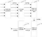
On the other hand, the embodiment of the invention also provides an FPGA circuit for image processing, which comprises an image acquisition circuit module, a storage circuit module, an image information acquisition circuit module and an image synthesis circuit module which are connected in sequence;
the image acquisition circuit module is used for acquiring a plurality of images of the same scene and storing the plurality of images to the storage circuit module; the image information acquisition circuit module is used for acquiring the plurality of images from the storage circuit module to acquire color values of pixels in the plurality of images; and the image synthesis circuit module is used for obtaining the color value of the pixel at the corresponding position in the synthesized image according to the color values of the pixels at the same position in the plurality of images.
Further, the circuit also includes an image correction circuit module for performing a color correction operation on the composite image.
According to the image processing method, the image processing device and the related circuit provided by the embodiment of the invention, the algorithm adopted by the image processing method can be realized on an FPGA (field programmable gate array), so that the synthesis of a plurality of LDR (low density direct conversion) images is quickly realized, an HDR (high density direct conversion) image is obtained, and the details of a dark part and a bright part are simultaneously displayed in one image.
Drawings
While the drawings needed to describe the invention or prior art arrangements in a more complete description of the embodiments or prior art are briefly described below, it should be apparent that the drawings described below are illustrative of some embodiments of the invention and that other drawings may be derived therefrom by those skilled in the art without the benefit of the inventive faculty.
Fig. 1 is a flowchart of an image processing method according to an embodiment of the present invention.
Fig. 2 is another flowchart of an image processing method according to an embodiment of the present invention.
Fig. 3 is a photoelectric conversion curve of the photosensor.
Fig. 4 is a flowchart of image color correction according to an embodiment of the present invention.
FIG. 5 is a graph of confidence versus brightness.
Fig. 6 is a block diagram of an image processing apparatus according to an embodiment of the present invention.
Fig. 7 is a block diagram of an image correction module according to an embodiment of the present invention.
Fig. 8 is a circuit block diagram of an FPGA for implementing the image processing method according to the embodiment of the present invention.
Fig. 9 is a block diagram of an FPGA for synthesizing pixel points in an HDR image according to an embodiment of the present invention.
Fig. 10 is a block diagram of an FPGA implementation for obtaining an optimal color value according to an embodiment of the present invention.
Fig. 11 is a block diagram of an FPGA implementation for correcting HDR image colors according to an embodiment of the present invention.
Detailed Description
In order to facilitate an understanding of the invention, a full description thereof will be given below with reference to the accompanying drawings. The invention may, however, be embodied in many different forms and should not be construed as limited to the embodiments set forth herein.
Unless defined otherwise, technical terms used herein have the same meaning as commonly understood by one of ordinary skill in the art.
In a natural scene, the brightness range of scene light is large, a common camera can only clearly image (LDR) in a narrow brightness range, and a plurality of LDR images clearly imaged in different brightness ranges (different exposure times are adopted by the camera) can be combined into an image clearly imaged in a wide brightness range (HDR). The technical contents of the present invention will be described below by way of specific examples.
In the embodiment of the present invention, referring to the flowchart shown in fig. 1, an image processing method provided in the embodiment of the present invention is specifically described as follows:
s01, acquiring a plurality of images of the same scene, wherein the exposure time of the images is different;
the LDR images with different brightness ranges are obtained by adopting different exposure times, specifically, by sequentially increasing the exposure times, and preferably, the exposure times corresponding to the sequentially obtained LDR images are an arithmetic progression.
S02, acquiring color values of pixels in the multiple images;
specifically, the technical scheme of the embodiment of the invention is realized based on RGB space, and the RGB space is used for realizing the RGB spaceThe red, green and blue light components characterize the brightness and color of the real scene. According to the RGB color model, the light value corresponding to the scene light emitted from the scene H in the real scene can be H ═ lr,lg,lb]Is shown in which lr、lg、lbRespectively a red light component, a green light component and a blue light component in the scene light emitted by the scene H. When the camera shoots, red light, green light and blue light are separated by the filter piece of the camera lens, the photoelectric sensors respectively collect the light intensity of the three components, the light signals are converted into electric signals, the electric signals obtained by the photoelectric sensors are used for generating black and white or color images, and the image shooting method is specifically realized through the mapping relation of scene light to image color values.
When scene light emitted by a scene H in a real scene is represented by brightness and color, the brightness value of the scene light can be represented by the sum of three components of red light, green light and blue light, specifically, L ═ Lr+lg+lb(ii) a The color value of scene light can be characterized by the ratio of red light, green light and blue light, and is specifically P ═ lr:lg:lb。
A simple mapping of light values of scene light emanating from the scene H to image color values will be given below.
In an embodiment of the present invention, for an LDR image, the light value H of the given scene light is ═ lr,lg,lb]After the image is formed by the camera, the color value of the pixel point corresponding to the generated image is [ r, g, b ]]Then, the correspondence between the light value of the scene light and the color value of the pixel point of the image is as follows:
r=ψ(arlr)+n, (1)
g=ψ(aglg)+n, (2)
b=ψ(ablb)+n, (3)
where n is noise, ar、ag、abIs constant for a given camera.
Correspondingly, the brightness value of the pixel point corresponding to the generated image is l ═ r + g + b.
And S03, obtaining a color value and a brightness value of a pixel at a corresponding position in the composite image according to the color values of the pixels at the same position in the plurality of images.
Specifically, the corresponding pixel color values of the pixel points at the same position in the plurality of LDR images are added, and the information of clear imaging in each LDR image is concentrated into one HDR image.
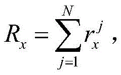
When a set of LDR images is combined into an HDR image, adding the corresponding pixel color values of the LDR images allows to compactly integrate the sharp imaged information in each LDR image into the same HDR image. According to the embodiment of the invention, the existing N LDR images are respectively represented by I1、I2、…、Ij、…INIs represented by the formula pxFor the pixel points at any position in the LDR image, the color value of each pixel point in each LDR image is Where j is the label of the corresponding LDR image. Pixel point p in the synthesized HDR imagexHas a new color value of [ R ]x,Gx,Bx]Then, there is the following formula:


accordingly, the pixel point p in the synthesized HDR image can be obtained by the equations (4), (5), and (6)xHas a brightness value of
In the present embodiment, referring to fig. 2, a flowchart of an image processing method provided by an embodiment of the present invention is shown.
In the first aspect, in the formulas (1), (2) and (3), a is a due to the fact that the filter of the camera has different filtering degrees for the red light component, the green light component and the blue light component, and the liker、ag、abThe values of these three constants will not be equal, which is also an important reason why the camera needs white balance;
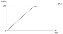
in a second aspect, the function ψ (x) in the equations (1), (2) and (3) substantially represents the photoelectric conversion performance of the photoelectric sensor, and as shown in fig. 3, when the light intensity is too large, the function ψ (x) enters a saturation region of the photoelectric conversion, and before the light intensity enters the saturation region, the function ψ (x) substantially represents the characteristic of a linear function, which corresponds to the embodiment of the present invention
In a third aspect, the camera is noisy when taking a picture or video.
In summary, due to ar、ag、abThe values of the three constants are different, and due to saturation regions existing in photoelectric conversion, noise and the like, a color distortion phenomenon occurs in an LDR image obtained by the camera.
The HDR synthesized by the foregoing embodiments of the invention may have a color distortion phenomenon due to the original distortion of the pixel colors in each LDR image during the acquisition process. Based on the above, further, the image processing method based on the FPGA further includes the steps of:
and S05, correcting the HDR image color.
Specifically, as shown in fig. 4, the HDR image color correction step includes:
s051, correcting the color value of scene light corresponding to each pixel point in the LDR image;
specifically, since the color value of the scene light in the real scene can be represented by the ratio of the red light component, the green light component, and the blue light component, in order to correct the distorted color, it is necessary to obtain the correct ratio of each pixel point in the HDR image to the red light component, the green light component, and the blue light component in the scene light, and the HDR image is synthesized from the LDR imageBefore obtaining the correct color value of the scene light corresponding to the HDR image, the corrected color value of the scene light corresponding to each LDR image, i.e. l of the scene light corresponding to the LDR image, needs to be obtainedr:lg:lbIs a correct value of lr:lg:lbCan pass through ar、ag、abThe ratio of three constants is obtained by calculating lr:lg:lbBefore the correct value of (A), first, a is obtainedr、ag、abRatio of three constants.
Optionally, in the mapping relationship between the light value of the scene light and the image color value, which is formed in the formula (1), the formula (2), and the formula (3), ar、ag、abThe ratio of these three constants can be found by white balance. Obtaining a by white balancer、ag、abAfter the ratio of the three constants, the correct l can be obtainedr:lg:lbThe value of (c). In an embodiment of the invention, standard a may be obtained by gray card imagingr、ag、abRatio of three constants.
Specifically, the camera images a gray card, which is not in the saturation region of the photosensor, and the gray value cannot be too small (the noise specific gravity is large), preferably, 18% gray card imaging is adopted, and the color value of the pixel point corresponding to the gray card is [ y ]r,yg,yb]In the embodiment of the present invention, there are:
ar:ag:ab=yr:yg:yb, (7)
when noise in an image is ignored, it is known from equations (1), (2) and (3)
r:g:b=ψ(arlr):ψ(aglg):ψ(ablb), (8)
In the linear region of the function ψ (x), the following equation is given:
ψ(arlr):ψ(aglg):ψ(ablb)=arlr:aglg:ablb, (9)
therefore, when ignoring noise in the image, the ratios of the three components of an LDR image are obtained according to equations (8) and (9) as follows:

color values [ y ] obtained by 18% Gray card imagingr,yg,yb]Can obtain ar、ag、abThe ratio of these three constants, in combination with equation (7), equation (10), and the color value [ r, g, b ] of the LDR image pixel]Corrected l can be obtainedr:lg:lbThe values of (A) are:

s052, calculating the optimal color value of the scene light corresponding to the pixel of the synthetic image;
given a set of N LDR images numbered I1、I2、…、Ij、…、INCorresponding to a certain pixel point p with the same position in the N imagesxThe color values of the N corrected scene lights can be calculated respectively:
Pj=lrj:lg j:lbj,
after the color values of the scene light corresponding to the N corrected LDR images obtained in the foregoing steps, the optimal color values of the scene light corresponding to the pixels in the HDR image are further obtained, and the optimal color values infinitely approximate to the real color values of the scene light.
Suppose that a pixel p at a corresponding position in the HDR image is synthesizedxThe optimal color value of the corresponding scene light is It can be known that when the brightness value of the scene light is in the saturation region of ψ (x), the corrected color value PiWill deviate from the true color value when the scene is illuminatedWhen the brightness value is smaller, the corrected color value P is obtained in the same way because the color value noise ratio of the pixel points in the LDR image is greatiWill deviate from the true color value.
For brightness LjAfter normalization, LDR image IjCalculated corrected color value PiConfidence θ (L) for true color valuej) Substantially gaussian, as shown in fig. 5.
Further, the confidence degree θ (L)j) Calculating optimal color values as correction parameters Optimum color value
 Can be obtained by maximum likelihood theorem calculation or by weighted sum. In the embodiment of the present invention, the calculation formula is specifically described as the following formula:

wherein Correcting the color value P for scene lightiIs the confidence of the true color value, rj,gj,bjThree components of the image pixel color value.


green light optimum color value Comprises the following steps:

optimum color value of blue light Comprises the following steps:

s053, calculating a corrected color value of the synthesized image according to the optimal color value;
the HDR image color value obtained by simple addition in the foregoing is [ R ]x,Gx,Bx]Let the corrected color value be [ R'x,G'x,B'x]And then:


thereby resulting in a color corrected HDR image.
In the embodiment of the present invention, when the HDR image is displayed by the display, the HDR image needs to be converted into the LDR image again before being displayed on the display because the dynamic range that the display can display is limited. For example, 4 LDR images with 8-bit color channels are processed by the method to obtain an HDR image with 10-bit color channels, but a single color channel of a current display is also 8-bit, when the HDR image is displayed on the display, the HDR image needs to be converted into an LDR image again, in order to retain information of the image as much as possible, in the conversion process, a contrast enhancement method is used to enhance image detail information (such as information of edges, textures, and the like).
In an embodiment of the present invention, an image processing apparatus is provided, as shown in a block diagram of fig. 6, and includes an image acquisition module 01, an image information acquisition module 02, and an image synthesis module 03. Preferably, the image processing apparatus further includes an image correction module 04 for correcting HDR image colors.
The image acquisition module 01 is configured to acquire a plurality of images of the same scene, wherein the plurality of images have different exposure times; specifically, the acquired images are all LDR images.
The image information obtaining module 02 obtains color values of pixels in the plurality of images by a user;
for an LDR image, the light value H of the scene light is given as [ l [ [ L ]r,lg,lb]After the image is formed by the camera, the color value of the pixel corresponding to the generated image is [ r, g, b ]]Then, the image information obtaining module 02 obtains the color value of the image pixel according to the following formula:
r=ψ(arlr)+n,
g=ψ(aglg)+n,
b=ψ(ablb)+n,
where n is noise, ar、ag、abIs constant for a given camera.
Accordingly, the image information obtaining module 02 further obtains the luminance value of the image pixel based on l ═ r + g + b.
The image synthesis module 03 is configured to obtain a color value and a luminance value of a pixel at a corresponding position in the synthesized image according to the color value and the luminance value of a pixel at the same position in the plurality of images.
Specifically, the image synthesis module 03 adds the color values of the pixels corresponding to the same position in the plurality of LDR images, and concentrates the clearly imaged information in each LDR image into one HDR image.
In this embodiment, the image synthesis module 03 obtains the color value of the synthesized image pixel based on the following formula:


accordingly, the image synthesis module 03 obtains the luminance value of the synthesized image pixel by:

since the color value of the scene light in the real scene can be represented by the ratio of the red light component, the green light component, and the blue light component, in order to correct the distorted color, it is necessary to obtain the correct ratio of the red light component, the green light component, and the blue light component in the scene light corresponding to each pixel point in the HDR image, and the HDR image is synthesized from the LDR images, and before obtaining the correct color value of the scene light corresponding to the HDR image, it is necessary to obtain the corrected color value of the scene light corresponding to each LDR image, that is, l of the scene light corresponding to the LDR imager:lg:lbIs a correct value of lr:lg:lbCan pass through ar、ag、abThe ratio of three constants is obtained by calculating lr:lg:lbBefore the correct value of (A), first, a is obtainedr、ag、abRatio of three constants. Specifically, as shown in fig. 7, the image correction module 04 includes a color value correction unit 041, an optimal color value acquisition unit 042, and a corrected color value acquisition unit 043.
The color value correction unit 041 obtains a by white balancer、ag、abAfter the ratio of three constants, the correct l is obtainedr:lg:lbThe value of (c). Based on the related art content of the foregoing embodiment, the color value correction unit 041 finally obtains lr:lg:lbHas a value of And will not be described in detail herein.
Also, based on the related art contents of the foregoing embodiments, the optimal color value obtaining unit 042 obtains an optimal color value based on the following formula:

wherein theta (L)j) To correct the color value PiIs the confidence of the true color value, rj,gj,bjThree components of the LDR image pixel color values.
By using To express, for a certain pixel point p in the imagexFinally, the optimum color value of the red light is obtained
 Comprises the following steps:

green light optimum color value Comprises the following steps:

optimum color value of blue light Comprises the following steps:

let the corrected color value be [ R'x,G'x,B'x]That is, the corrected color value obtaining unit 043 obtains a corrected color value of the synthesized image based on the following expression:

optionally, an image mapping unit 05 is further included for remapping the synthesized HDR image to an LDR image for display on a display.
In the embodiment of the invention, an FPGA circuit for realizing the image processing method is provided. Specifically, as shown in the block diagram of fig. 8, the FPGA circuit includes an image acquisition circuit module 11, a storage circuit module 12, an image information acquisition circuit module 13, and an image synthesis circuit module 14, which are connected in sequence.
The image acquisition circuit module and the image information acquisition circuit module are both connected to the storage circuit module, the image acquisition circuit module acquires an image in a real scene and then stores the generated LDR image in the storage circuit module, the image information acquisition circuit module reads the LDR image information from the storage module, and the storage module comprises but is not limited to a Static Random Access Memory (SRAM), an electrically erasable programmable read-only memory (EEPROM), an erasable programmable read-only memory (EPROM), a programmable read-only memory (PROM), a read-only memory (ROM), a magnetic memory, a flash memory, a magnetic disk or an optical disk and the like.
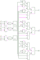
As can be known from the related art in the image processing method provided in the foregoing embodiment, the image synthesis circuit module 14 obtains the color value of the HDR image pixel by the following formula:


specifically, an implementation block diagram of an FPGA for synthesizing pixel points in an HDR image is shown in fig. 9.
Preferably, the FPGA circuit further includes an image correction circuit module 15, and based on the related art in the image processing method provided in the foregoing embodiment, the image correction circuit module 15 obtains an optimal color value of the HDR image for the scene light by the following formula:

wherein is made of To express, for a certain pixel point p in the imagexOptimum color value of red light
 Comprises the following steps:

green light optimum color value Comprises the following steps:

optimum color value of blue light Comprises the following steps:

specifically, an optimum color value is obtained The FPGA implementation block diagram of fig. 10.
After obtaining the optimal color value, let the corrected color value be [ R'x,G'x,B'x]That is, the image correction circuit module 15 further obtains the corrected color value of the synthesized image by:

thereby resulting in a color corrected HDR image. The FPGA block diagram is shown in FIG. 11.
Optionally, the FPGA circuit further comprises an image mapping circuit module 16 for remapping the combined HDR image into an LDR image for display on a display. '
According to the image processing method, the image processing device and the related circuit provided by the embodiment of the invention, the algorithm adopted by the image processing method can be realized on an FPGA (field programmable gate array), so that the synthesis of a plurality of LDR (low density direct conversion) images is quickly realized, an HDR (high density direct conversion) image is obtained, and the details of a dark part and a bright part are simultaneously displayed in one image.
Although the present invention has been described in detail with reference to the foregoing embodiments, it will be apparent to those skilled in the art that modifications may be made to the embodiments described in the foregoing detailed description, or equivalent changes may be made in some of the features of the embodiments described above. All equivalent structures made by using the contents of the specification and the attached drawings of the invention can be directly or indirectly applied to other related technical fields, and are also within the protection scope of the patent of the invention.
Claims (6)
1. An image processing method is realized based on an FPGA, and is characterized by comprising the following steps:
acquiring a plurality of images of the same scene, wherein the exposure time of the plurality of images is different;
acquiring color values of pixels in the plurality of images;
obtaining a color value of a pixel at a corresponding position in the synthesized image according to the color values of the pixels at the same position in the plurality of images;
performing a color correction operation on the composite image;
wherein the color correction operation step comprises:
correcting color values of scene light corresponding to pixels in the plurality of images; wherein the step of correcting the color values of the scene light corresponding to the pixels in the plurality of images comprises: obtaining three constants a in each LDR image through white balance on the basis of neglecting noise in the imager、ag、abThe standard ratio therebetween; obtaining the correct ratio of the red light component, the green light component and the blue light component in the scene light corresponding to each LDR image according to the standard ratio of the three constants so as to correct the distorted color;
calculating the optimal color value of the scene light corresponding to the synthesized image pixel according to the corrected color value;
calculating a corrected color value of the composite image according to the optimal color value;
wherein, in each LDR image, the light value H corresponding to the scene light emitted by the given scene is ═ lr,lg,lb]After the image is formed by the camera, the color value of the pixel point corresponding to the generated image is [ r, g, b ]]The correspondence between the light value of the scene light and the color value of the pixel point of the image is as follows:
r=ψ(arlr)+n
g=ψ(aglg)+n
b=ψ(ablb)+n
wherein n is noise;
ar、ag、abis constant for a given camera, and ar、ag、abThe ratio between the gray scale and the gray scale is equal to the color value [ y ] of the corresponding pixel point of the gray scale in the gray scale imaging processr,yg,yb]The corresponding relation is ar:ag:ab=yr:yg:yb;
The function psi (x) is a linear function for embodying the photoelectric conversion performance of the photoelectric sensor for respectively collecting the light intensity of the red light, the green light and the blue light after being separated by the optical filter;
lr、lg、lbred light component, green light component and blue light component in scene light emitted by a given scene respectively;
according to ar、ag、abThe corrected LDR image corresponds to the red, green and blue light components l in the scene lightr:lg:lbThe correct ratio of (A) to (B) is:

2. the image processing method of claim 1, wherein the composite image pixel color values are obtained by:


wherein the content of the first and second substances, for pixel color values of the plurality of images, Rx,Gx,BxIn order to synthesize the color values of the image,
 and RxIn correspondence with the red light component,
 and GxCorresponding to the green light component, and,
 and BxCorresponding to the blue light component.
3. The image processing method according to claim 2, wherein the optimal color value is obtained by:


wherein The optimum color value for the red light is,
 the optimum color value for the green light is,
 for the best color value of the blue light,
 to correct the parameters, ar、ag、abIs a constant.
4. The image processing method according to claim 3, wherein the corrected color values are obtained by:


wherein R isx,Gx,BxColor value of the synthesized-before-correction image, R'x,G'x,B'xIs the color value of the corrected composite image.
5. An image processing apparatus characterized by comprising:
the system comprises an image acquisition module, a processing module and a display module, wherein the image acquisition module is used for acquiring a plurality of images of the same scene, and the exposure time of the images is different;
the image information acquisition module is used for acquiring color values of pixels in the plurality of images;
the image synthesis module is used for obtaining the color value of the pixel at the corresponding position in the synthesized image according to the color values of the pixels at the same position in the plurality of images; and
an image correction module for performing a color correction operation on the composite image;
wherein the image correction module employs the color correction operation method according to any one of claims 1 to 4, including:
a color value correction unit for correcting color values of scene light corresponding to pixels in the plurality of images;
an optimal color value obtaining unit for calculating an optimal color value of the scene light corresponding to the synthesized image pixel; and
and the correction color value acquisition unit is used for calculating the correction color value of the synthesized image according to the optimal color value.
6. An FPGA circuit for image processing is characterized in that the circuit comprises an image acquisition circuit module, a storage circuit module, an image information acquisition circuit module, an image synthesis circuit module and an image correction circuit module which are connected in sequence;
the image acquisition circuit module is used for acquiring a plurality of images of the same scene and storing the plurality of images to the storage circuit module; the image information acquisition circuit module is used for acquiring the plurality of images from the storage circuit module to acquire color values of pixels in the plurality of images; the image synthesis circuit module is used for obtaining the color value of the pixel at the corresponding position in the synthesized image according to the color values of the pixels at the same position in the plurality of images; the image correction circuit block for performing a color correction operation on the composite image according to the color correction operation method of any one of claims 1 to 4.
Priority Applications (1)
| Application Number | Priority Date | Filing Date | Title |
|---|---|---|---|
| CN201610662563.6A CN107734246B (en) | 2016-08-12 | 2016-08-12 | Image processing method, device and related circuit |
Applications Claiming Priority (1)
| Application Number | Priority Date | Filing Date | Title |
|---|---|---|---|
| CN201610662563.6A CN107734246B (en) | 2016-08-12 | 2016-08-12 | Image processing method, device and related circuit |
Publications (2)
| Publication Number | Publication Date |
|---|---|
| CN107734246A CN107734246A (en) | 2018-02-23 |
| CN107734246B true CN107734246B (en) | 2020-09-15 |
Family
ID=61199934
Family Applications (1)
| Application Number | Title | Priority Date | Filing Date |
|---|---|---|---|
| CN201610662563.6A Active CN107734246B (en) | 2016-08-12 | 2016-08-12 | Image processing method, device and related circuit |
Country Status (1)
| Country | Link |
|---|---|
| CN (1) | CN107734246B (en) |
Families Citing this family (1)
| Publication number | Priority date | Publication date | Assignee | Title |
|---|---|---|---|---|
| CN113271393B (en) * | 2021-07-19 | 2021-10-15 | 浙江华睿科技股份有限公司 | Multi-band flat field correction method, device and computer readable medium |
Citations (3)
| Publication number | Priority date | Publication date | Assignee | Title |
|---|---|---|---|---|
| CN103124358A (en) * | 2011-11-18 | 2013-05-29 | 株式会社其恩斯 | Image processing apparatus and image processing method |
| CN104125408A (en) * | 2013-04-28 | 2014-10-29 | 比亚迪股份有限公司 | High dynamic range image processing method and device |
| CN105812761A (en) * | 2015-08-03 | 2016-07-27 | 维沃移动通信有限公司 | Image color reduction method and terminal |
Family Cites Families (1)
| Publication number | Priority date | Publication date | Assignee | Title |
|---|---|---|---|---|
| US20120106840A1 (en) * | 2010-10-28 | 2012-05-03 | Amit Singhal | Combining images captured with different color patterns |
-
2016
- 2016-08-12 CN CN201610662563.6A patent/CN107734246B/en active Active
Patent Citations (3)
| Publication number | Priority date | Publication date | Assignee | Title |
|---|---|---|---|---|
| CN103124358A (en) * | 2011-11-18 | 2013-05-29 | 株式会社其恩斯 | Image processing apparatus and image processing method |
| CN104125408A (en) * | 2013-04-28 | 2014-10-29 | 比亚迪股份有限公司 | High dynamic range image processing method and device |
| CN105812761A (en) * | 2015-08-03 | 2016-07-27 | 维沃移动通信有限公司 | Image color reduction method and terminal |
Also Published As
| Publication number | Publication date |
|---|---|
| CN107734246A (en) | 2018-02-23 |
Similar Documents
| Publication | Publication Date | Title |
|---|---|---|
| US10091479B2 (en) | Hardware-based convolutional color correction in digital images | |
| JP6351903B1 (en) | Image processing apparatus, image processing method, and photographing apparatus | |
| CN108055452A (en) | Image processing method, device and equipment | |
| EP3123710B1 (en) | System and method of fast adaptive blending for high dynamic range imaging | |
| CN108717691B (en) | Image fusion method and device, electronic equipment and medium | |
| CN108156369B (en) | Image processing method and device | |
| JP2010220184A (en) | Dark space exposure compensation method for simulating high dynamic range by single image and image processor employing the same | |
| KR102102740B1 (en) | Image processing apparatus and image processing method | |
| KR20150109177A (en) | Photographing apparatus, method for controlling the same, and computer-readable recording medium | |
| US20180025476A1 (en) | Apparatus and method for processing image, and storage medium | |
| Kao et al. | Design considerations of color image processing pipeline for digital cameras | |
| JP2015154102A (en) | Image processing apparatus and method, image processing program, imaging device | |
| KR20120114899A (en) | Image processing method and image processing apparatus | |
| Kao | High dynamic range imaging by fusing multiple raw images and tone reproduction | |
| CN111970432A (en) | Image processing method and image processing device | |
| CN102339461A (en) | Method and equipment for enhancing image | |
| CN107682611B (en) | Focusing method and device, computer readable storage medium and electronic equipment | |
| CN107734246B (en) | Image processing method, device and related circuit | |
| JP2015192338A (en) | Image processing device and image processing program | |
| JP4359662B2 (en) | Color image exposure compensation method | |
| CN107317968A (en) | Image defogging method, device, computer can storage medium and mobile terminals | |
| CN109447925B (en) | Image processing method and device, storage medium and electronic equipment | |
| JP5050141B2 (en) | Color image exposure evaluation method | |
| Wang et al. | Retinex-based color correction for displaying high dynamic range images | |
| Singh et al. | Detail Enhanced Multi-Exposer Image Fusion Based on Edge Perserving Filters |
Legal Events
| Date | Code | Title | Description |
|---|---|---|---|
| PB01 | Publication | ||
| PB01 | Publication | ||
| SE01 | Entry into force of request for substantive examination | ||
| SE01 | Entry into force of request for substantive examination | ||
| GR01 | Patent grant | ||
| GR01 | Patent grant |