CN1077329C - Circuit breaker - Google Patents
Circuit breaker Download PDFInfo
- Publication number
- CN1077329C CN1077329C CN96100626A CN96100626A CN1077329C CN 1077329 C CN1077329 C CN 1077329C CN 96100626 A CN96100626 A CN 96100626A CN 96100626 A CN96100626 A CN 96100626A CN 1077329 C CN1077329 C CN 1077329C
- Authority
- CN
- China
- Prior art keywords
- output
- harmonic wave
- checkout gear
- definite value
- current
- Prior art date
- Legal status (The legal status is an assumption and is not a legal conclusion. Google has not performed a legal analysis and makes no representation as to the accuracy of the status listed.)
- Expired - Fee Related
Links
Images

Classifications
-
- H—ELECTRICITY
- H01—ELECTRIC ELEMENTS
- H01H—ELECTRIC SWITCHES; RELAYS; SELECTORS; EMERGENCY PROTECTIVE DEVICES
- H01H83/00—Protective switches, e.g. circuit-breaking switches, or protective relays operated by abnormal electrical conditions otherwise than solely by excess current
- H01H83/20—Protective switches, e.g. circuit-breaking switches, or protective relays operated by abnormal electrical conditions otherwise than solely by excess current operated by excess current as well as by some other abnormal electrical condition
-
- H—ELECTRICITY
- H01—ELECTRIC ELEMENTS
- H01H—ELECTRIC SWITCHES; RELAYS; SELECTORS; EMERGENCY PROTECTIVE DEVICES
- H01H71/00—Details of the protective switches or relays covered by groups H01H73/00 - H01H83/00
- H01H71/04—Means for indicating condition of the switching device
Abstract
To avoid a sudden unexpected interruption by generating an alarm output when the higher harmonics of an incoming and distributing system exceed a prescribed value. A master current is detected by current transformers 11-15, its secondary output current is rectified by a commutator 15, and an internal circuit power source is generated by a power source circuit 16, while a detected current is transmitted to a MPU 18 through a signal detecting circuit 17. In the MPU 18, the content ratio of n-order higher harmonics is calculated. The calculation data is compared with a value preset by a characteristic setting part 19 in the MPU 18, and when it exceeds the set value, an alarm is displayed, and an alarm output is also generated. At that time, alarm/interruption can be selected by the distortion of the current waveform.
Description
The present invention relates to have the circuit breaker of warning function, relate in particular to and be suitable for by detecting the circuit breaker that harmonic current is reported to the police.
Office automation (OA) equipment and inverter controller produce a large amount of harmonic waves, and harmonic wave has adverse effect to other electric installation and device.As the measure that overcomes these adverse effects, various types of filters or similar device have been installed, so far to suppress the harmonic measure that the harmonic wave desired data carries out and analyze be to carry out on the level of measuring instrument in order to obtain, and promptly only shows and write down the value that measurement (detection) is arrived.For example, as the Furuya on Kenchikusetsubishi94-8 phase: the Furuya's on " harmonic wave countermeasure (1) ", Kenchikusetsubishi94-11 phase: the Sekimoto's on " harmonic wave countermeasure (2) ", Kenchikusetsubishi92-5 phase etc.: harmonic analysis and countermeasure of discussing in " harmonic problem status investigation in the existing structure ".
Above-mentioned prior art only shows and record, and the result in order to understand fully the influence of harmonic with the load operation working conditions change, needs harmonic wave is measured and record for a long time; And will take some countermeasures, after measurement, also need further human intervention.In addition, because the harmonic wave detecting unit of above-mentioned prior art is to be installed separately with the circuit breaker that is subjected to electroplax or distribution panelboard, thereby have a problem: the harmonic wave detecting unit is installed in the enough reliable space of needs, but in fact the harmonic wave detecting unit can not be installed in the power panel.
The present invention is exactly in order to address the above problem, and its objective is to provide to have the circuit breaker that detects harmonic effects and start warning function.
According to an aspect of the present invention, for achieving the above object, provide a kind of circuit breaker, it comprises the power line conductor with logical-disconnected contact, and described power line conductor links to each other with distribution system at opposite side with the electric power receiving system in a side; Detect the current sensing means of electric current in the power line; When the tripgear of logical-disconnected contact takes place to disconnect when unusual electric current; Detect the harmonic wave checkout gear of harmonic components from the output of current sensing means; With the output of harmonic wave checkout gear and definite value compares and produce the comparison means of output during greater than definite value when the output of harmonic wave checkout gear; And the alarm output device that produces warning according to the output of comparison means.
Being converted into form factor (hereinafter referred to as C.F.) by the detected electric current of current sensing means promptly is converted into effective value/peak value or forms nth harmonic in follow-up phase by arithmetic operating apparatus, and surpass when adjusting the level that piece determines by characteristic when harmonic wave, just send and report to the police or breaker contact point is disconnected.
According to the present invention, when harmonic current surpasses setting, can before breaker contact point disconnects, send warning, thereby can avoid disconnection suddenly and protection equipment not to be subjected to influence of harmonic.
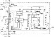
Fig. 1 is a circuit breaker loop block diagram according to an embodiment of the invention.
Fig. 2 is the profile of circuit breaker according to an embodiment of the invention.
Below with reference to Fig. 1 and Fig. 2 most preferred embodiment of the present invention is introduced.
Present embodiment represents that the present invention is used to the situation with the four-pole circuit breaker of center line.
Fig. 1 is a circuit breaker loop block diagram according to an embodiment of the invention, and Fig. 2 is the structure chart with the circuit breaker in this loop.The present embodiment circuit breaker has power supply side terminal 1,2,3 and 4 in a side, correspondingly at opposite side load side terminal 5,6,7 and 8 is arranged, and they are contained in the shell of being made up of housing 41 and cap 43 42.Provide U power line conductor 24U mutually 5 of power supply side terminal 1 and load side terminals, provide V power line conductor 24V mutually 6 of power supply side terminal 2 and load side terminals, provide W power line conductor 24W mutually 7 of power supply side terminal 3 and load side terminals, provide N power line conductor 24N mutually 8 of power supply side terminal 4 and load side terminals.In addition, between these power line conductor, also be inserted with logical- disconnected contact 25U, 25W, 25V and 25N.Make logical- disconnected contact 25U, 25W, 25V and 25N open and close under the normal condition by control crank 44, disconnect in the tripping operation action that takes place such as overcurrent, unsymmetrical current or harmonic wave etc. when unusual then by tripping mechanism 21.Disclosed release mechanism (giving an example) can be used as above-mentioned tripping mechanism among JP-A-61-151945. Current transformer 11,12,13 and 14 current sensing meanss that then can be used as on power line conductor 24U, 24V, 24W and the 24N.The V that Fig. 2 represents to have handle 44 and release mechanism is the sectional view of power line conductor mutually.
The output of current transformer is supplied to electric power loop 16 and input loop 17 by rectifier 15.Electric power loop adjust commutating circuit 15 output so that its remain constant voltage and with this constant voltage supply with input loop 17, as arithmetic operating apparatus MPU18, characteristic tuning device 19, attention display 20, tripping mechanism 21 and as the warning output loop 22 of alarm output device.
Rectifier 15, electric power loop 16, input loop 17, MPU18, characteristic tuning device 19, attention display 20 and warning output loop 22 are installed on the circuit board 46, and circuit board 46 is installed in the cap 43 and be positioned at housing 42 upper positions so that can read shows signal on the attention display by the transparent part of cap 43.In the present embodiment, lead-out terminal 30 is by the connector that makes it possible to receive from the surface of cap 43 the such formation of output.
To MPU18 by following programming: calculate harmonic components from the output of detected current transformer 11,12,13 and 14, when the system harmonics electric current surpasses first definite value, sending the output of reporting to the police, and send the circuit open command during above second definite value when harmonic current.Circuit according to this instruction disconnects the time response that action has the harmonic wave tolerance limit that meets load.
C.F. value, n-subharmonic value or current in middle wire value can be used for first or second definite value.
MPU18 is based on the harmonic component amplitude, and the C.F. that more specifically says so calculates respectively amount, or utilizes and pay a upright leaf unfolding calculation n-subharmonic content, and therefore detection has or not harmonic wave or humorous wave amplitude.C.F. and the calculating of n-subharmonic content be well-known, omit its introduction herein.MPU18 will compare about the result of calculation and the predetermined value of harmonic wave, if surpassed this definite value, just sends warning by attention display 20, and provides the output of reporting to the police by warning output loop 22.At this moment, can be according to determining whether that as being used to the predetermined threshold that only provides the warning or also want second definite value of cut-off breaker determines whether only to provide warning or also wants cut-off breaker.When cutoff circuit, according to the time response of the harmonic wave tolerance limit that is suitable for loading, circuit breaker disconnects in the back of exceeding schedule time.In other words, in the present embodiment, MPU18 has the function of harmonic wave checkout gear and comparison means.
According to present embodiment, by a plurality of definite values and detection C.F. or the n-subharmonic adjusted, can before switch disconnects, send warning, thereby may prevent unexpected cut-off breaker (hereinafter referred to as unexpected disconnection) under the situation that is not having prompting in advance.Or, when sending alarm signal,, can prevent that these devices are damaged by isolating device to the responsive or easy influence from harmonic of harmonic wave.
In addition, by the electric current among the center line conductor 24N and the value of adjusting at characteristic tuning device 19 are compared, just may avoid current in middle wire being increased and to the adverse effect of device by harmonic wave.
When harmonic current surpasses a setting, can before circuit breaker disconnects, send alarm signal according to the present invention, can avoid unexpected disconnection.In addition, but protective device is not subjected to influence of harmonic.
Claims (4)
1. circuit breaker, power line conductor current sensing means and tripgear with band on-off contact, described on-off contact links to each other with distribution system with the electric power receiving system, described current sensing means detects the electric current that flows through power line conductor, described tripgear takes place to disconnect described on-off contact when unusual at electric current, it is characterized in that comprising:
Be used for detecting the harmonic wave checkout gear of harmonic component according to the output of described current sensing means;
Be used for relatively, produce the comparison means of an output during greater than this definite value when the output of described harmonic wave checkout gear one of the output of described harmonic wave checkout gear and this harmonic wave checkout gear predetermined definite value; And
Be used for producing the alarm output device of the output of reporting to the police according to the output of described comparison means,
Wherein, described comparison means with the output of described harmonic wave checkout gear and its first definite value and greater than second definite value of first definite value relatively, when the output of described harmonic wave checkout gear surpasses described first definite value, described comparison means provides an output to described alarm output device, and when the output of described harmonic wave checkout gear surpassed described second definite value, described comparison means provided an output to described tripgear.
2. according to the circuit breaker of claim 1, wherein said harmonic wave checkout gear and described comparison means are made of arithmetic operating apparatus, so constitute described arithmetic operating apparatus, make its time response according to the harmonic wave tolerance limit that is suitable for loading carry out opening operation.
3. according to the circuit breaker of claim 1, wherein, described harmonic wave checkout gear and described comparison means are made of arithmetic operating apparatus, so constitute described arithmetic operating apparatus, make its amplitude evaluation based on the harmonic component of the output of described current sensing means, this numerical value and described definite value are compared, and when this numerical value surpasses described definite value, produce output.
4. according to the circuit breaker of claim 3, wherein, the numerical value of described amplitude based on described harmonic component is a value in form factor, n-subharmonic value and the current in middle wire at least.
Applications Claiming Priority (3)
| Application Number | Priority Date | Filing Date | Title |
|---|---|---|---|
| JP7001015A JPH08190851A (en) | 1995-01-09 | 1995-01-09 | Circuit breaker |
| JP001015/1995 | 1995-01-09 | ||
| JP001015/95 | 1995-01-09 |
Publications (2)
| Publication Number | Publication Date |
|---|---|
| CN1137685A CN1137685A (en) | 1996-12-11 |
| CN1077329C true CN1077329C (en) | 2002-01-02 |
Family
ID=11489757
Family Applications (1)
| Application Number | Title | Priority Date | Filing Date |
|---|---|---|---|
| CN96100626A Expired - Fee Related CN1077329C (en) | 1995-01-09 | 1996-01-08 | Circuit breaker |
Country Status (3)
| Country | Link |
|---|---|
| JP (1) | JPH08190851A (en) |
| KR (1) | KR100196016B1 (en) |
| CN (1) | CN1077329C (en) |
Families Citing this family (8)
| Publication number | Priority date | Publication date | Assignee | Title |
|---|---|---|---|---|
| KR100922265B1 (en) * | 2007-08-20 | 2009-10-15 | 엘에스산전 주식회사 | Breaker |
| JP5212005B2 (en) * | 2008-10-08 | 2013-06-19 | 三菱電機株式会社 | Electronic circuit breaker |
| JP5243344B2 (en) * | 2009-05-20 | 2013-07-24 | 三菱電機株式会社 | Circuit breaker |
| WO2013125255A1 (en) * | 2012-02-21 | 2013-08-29 | 株式会社 東芝 | Integration unit and protection relay system |
| CN104217871A (en) * | 2013-06-05 | 2014-12-17 | 施耐德电器工业公司 | Multifunctional isolating switch |
| WO2015159364A1 (en) * | 2014-04-15 | 2015-10-22 | 三菱電機株式会社 | Circuit breaker |
| GB2538087B (en) * | 2015-05-06 | 2019-03-06 | Torro Ventures Ltd | Analysing a power circuit |
| US11726117B2 (en) | 2020-04-30 | 2023-08-15 | Florida Power & Light Company | High frequency data transceiver and surge protection retrofit for a smart meter |
Citations (2)
| Publication number | Priority date | Publication date | Assignee | Title |
|---|---|---|---|---|
| US4104687A (en) * | 1976-11-24 | 1978-08-01 | S&C Electric Company | Device for detecting unbalanced conditions in a polyphase equipment bank |
| JPH03135324A (en) * | 1989-10-18 | 1991-06-10 | Fuji Electric Co Ltd | Higher harmonic current monitoring and warning apparatus |
-
1995
- 1995-01-09 JP JP7001015A patent/JPH08190851A/en active Pending
-
1996
- 1996-01-08 KR KR1019960000188A patent/KR100196016B1/en not_active IP Right Cessation
- 1996-01-08 CN CN96100626A patent/CN1077329C/en not_active Expired - Fee Related
Patent Citations (2)
| Publication number | Priority date | Publication date | Assignee | Title |
|---|---|---|---|---|
| US4104687A (en) * | 1976-11-24 | 1978-08-01 | S&C Electric Company | Device for detecting unbalanced conditions in a polyphase equipment bank |
| JPH03135324A (en) * | 1989-10-18 | 1991-06-10 | Fuji Electric Co Ltd | Higher harmonic current monitoring and warning apparatus |
Also Published As
| Publication number | Publication date |
|---|---|
| KR100196016B1 (en) | 1999-06-15 |
| CN1137685A (en) | 1996-12-11 |
| KR960030288A (en) | 1996-08-17 |
| JPH08190851A (en) | 1996-07-23 |
Similar Documents
| Publication | Publication Date | Title |
|---|---|---|
| CA2320859C (en) | Electrical fault detection system | |
| EP1103057B1 (en) | Arc fault detection system | |
| US5182547A (en) | Neutral wire current monitoring for three-phase four-wire power distribution system | |
| US6218844B1 (en) | Method and apparatus for testing an arcing fault circuit interrupter | |
| CN1077329C (en) | Circuit breaker | |
| JPH07322473A (en) | Digital control type interrupter automatically selecting sampling interval | |
| CA2145471C (en) | Overcurrent trip unit with separately adjustable neutral protection | |
| CN111579934A (en) | Method and device for realizing electric safety monitoring of external power network of base station and base station | |
| KR102040573B1 (en) | Arc detection apparatus using composite sensor | |
| WO1993012436A1 (en) | Fault indicator for power lines | |
| KR100290575B1 (en) | Apparatus for monitoring insulation of non-grounded power line | |
| US4675598A (en) | Current measuring device in an electrical distribution switchboard or enclosure | |
| KR101030925B1 (en) | Solar power generation system with monitoring and neutral line replacement | |
| US4532568A (en) | Three-phase leakage protection by electronic control | |
| KR20180115451A (en) | Digital electric distribution equipment for display of protective relay condition | |
| EP1448997A2 (en) | Energy consumption control unit | |
| CN213813746U (en) | Residual current protection and data output circuit | |
| KR100691612B1 (en) | Monitoring system of disconnection for Reactor coil | |
| JPH0879987A (en) | Power load monitoring system | |
| JP3360968B2 (en) | Protective relay | |
| CN111736041A (en) | Fault arc monitoring device and method | |
| CN116632789A (en) | Comprehensive online monitoring, analyzing and protecting method and system for switch cabinet | |
| JPH06165368A (en) | High frequency trouble preventive method | |
| SU1032509A1 (en) | Device for protective de-energization of a.c.electrical installation | |
| JPH06153380A (en) | Anti-burning system of dc reactor for power factor improving capacitor in transforming facility |
Legal Events
| Date | Code | Title | Description |
|---|---|---|---|
| C10 | Entry into substantive examination | ||
| SE01 | Entry into force of request for substantive examination | ||
| C06 | Publication | ||
| PB01 | Publication | ||
| C14 | Grant of patent or utility model | ||
| GR01 | Patent grant | ||
| REG | Reference to a national code |
Ref country code: HK Ref legal event code: GR Ref document number: 1002552 Country of ref document: HK |
|
| C19 | Lapse of patent right due to non-payment of the annual fee | ||
| CF01 | Termination of patent right due to non-payment of annual fee |