CN1076448C - DC blasting vane wheel - Google Patents
DC blasting vane wheel Download PDFInfo
- Publication number
- CN1076448C CN1076448C CN97102053A CN97102053A CN1076448C CN 1076448 C CN1076448 C CN 1076448C CN 97102053 A CN97102053 A CN 97102053A CN 97102053 A CN97102053 A CN 97102053A CN 1076448 C CN1076448 C CN 1076448C
- Authority
- CN
- China
- Prior art keywords
- vane wheel
- blade
- blasting vane
- decided
- periodicity
- Prior art date
- Legal status (The legal status is an assumption and is not a legal conclusion. Google has not performed a legal analysis and makes no representation as to the accuracy of the status listed.)
- Expired - Lifetime
Links
Images


Classifications
-
- F—MECHANICAL ENGINEERING; LIGHTING; HEATING; WEAPONS; BLASTING
- F04—POSITIVE - DISPLACEMENT MACHINES FOR LIQUIDS; PUMPS FOR LIQUIDS OR ELASTIC FLUIDS
- F04D—NON-POSITIVE-DISPLACEMENT PUMPS
- F04D29/00—Details, component parts, or accessories
- F04D29/66—Combating cavitation, whirls, noise, vibration or the like; Balancing
- F04D29/661—Combating cavitation, whirls, noise, vibration or the like; Balancing especially adapted for elastic fluid pumps
- F04D29/666—Combating cavitation, whirls, noise, vibration or the like; Balancing especially adapted for elastic fluid pumps by means of rotor construction or layout, e.g. unequal distribution of blades or vanes
-
- F—MECHANICAL ENGINEERING; LIGHTING; HEATING; WEAPONS; BLASTING
- F04—POSITIVE - DISPLACEMENT MACHINES FOR LIQUIDS; PUMPS FOR LIQUIDS OR ELASTIC FLUIDS
- F04D—NON-POSITIVE-DISPLACEMENT PUMPS
- F04D17/00—Radial-flow pumps, e.g. centrifugal pumps; Helico-centrifugal pumps
- F04D17/02—Radial-flow pumps, e.g. centrifugal pumps; Helico-centrifugal pumps having non-centrifugal stages, e.g. centripetal
- F04D17/04—Radial-flow pumps, e.g. centrifugal pumps; Helico-centrifugal pumps having non-centrifugal stages, e.g. centripetal of transverse-flow type
-
- F—MECHANICAL ENGINEERING; LIGHTING; HEATING; WEAPONS; BLASTING
- F04—POSITIVE - DISPLACEMENT MACHINES FOR LIQUIDS; PUMPS FOR LIQUIDS OR ELASTIC FLUIDS
- F04D—NON-POSITIVE-DISPLACEMENT PUMPS
- F04D29/00—Details, component parts, or accessories
- F04D29/26—Rotors specially for elastic fluids
- F04D29/28—Rotors specially for elastic fluids for centrifugal or helico-centrifugal pumps for radial-flow or helico-centrifugal pumps
- F04D29/281—Rotors specially for elastic fluids for centrifugal or helico-centrifugal pumps for radial-flow or helico-centrifugal pumps for fans or blowers
- F04D29/282—Rotors specially for elastic fluids for centrifugal or helico-centrifugal pumps for radial-flow or helico-centrifugal pumps for fans or blowers the leading edge of each vane being substantially parallel to the rotation axis
- F04D29/283—Rotors specially for elastic fluids for centrifugal or helico-centrifugal pumps for radial-flow or helico-centrifugal pumps for fans or blowers the leading edge of each vane being substantially parallel to the rotation axis rotors of the squirrel-cage type
Abstract
To reduce its rotational noise in a particular frequency band, the cross flow fan impeller comprises a plurality of division plates 3 perpendicular to the rotational axis and a plurality of blades 1 provided between each pair of division plates 3. The angular location of the blades is varied cyclically based on a specific equation.
Description
The present invention relates to the through-flow blasting vane wheel, this impeller can suppress the especially generation of low-frequency band noise of impeller rotation sound.
Existing air conditioner indoor unit 5 as shown in Figure 7, lower portion is being provided with exhaust nozzle 7 in the front of casing 6, and air suction inlet 8 is being set above it, is disposing heat exchanger 9 at these air suction inlet 8 rear sides.To carry out heat exchange by heat exchanger 9 from the air that air suction inlet 8 imports by the through-flow blasting vane wheel 4 that is configured between casing 6 and the heat exchanger 9, become cold wind or warm braw, be blown into indoor from air nozzle 7 again.
As shown in Figure 8, above-mentioned through-flow blasting vane wheel has perpendicular to several dividing plates 3 of running shaft with periodic intervals and is installed in several blades 1 between aforementioned barriers.In order to lower the sound that produces when impeller 4 rotates, the fan rotation sound (hereinafter referred to as NZ sound) relevant with blade quantity, once there were many schemes to be suggested, for example: open the Japanese patent gazette spy and promptly once to have disclosed a kind of impeller in clear 60-17296 number, the installation interval aperiodicity of the blade 1 of this impeller is disposing randomly.
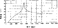
Existing blasting vane wheel structure as above-mentioned, Fig. 9 represents that blade installation has the level of noise frequency analysis result of periodic impeller at interval.Figure 10 represents that above-mentioned spy opens the level of noise frequency analysis result of the acyclic impeller in blade installation interval of clear 60-17296 communique announcement.As seen, open shown in the clear 60-17296 communique, can lower the NZ sound, as shown in figure 10, newly produced the following low frequency noise of 600Hz again though blade is installed according to the spy.
Figure 10 is to simulating the result according to the frequency analysis of following formula (2) when disposing blade randomly.
Formula (2)
θ
k=θ
k0+dθ×(rnd(δ)-δ/2)
In the formula, θ
k: the arrangement angles of determining the blade installation position
θ
k0: the arrangement angles during with impartial arranged spaced
D θ: the blade space angle degree during impartial arranged spaced
Rnd (): random numbers produces function
δ: torsional deformation coefficient
K: the blade that will be configured in the benchmark angle this blade numbering during as O
When the blade 1 of through-flow blasting vane wheel 4 by stabilizer 10 near the time, because of the variation in pressure trigger noise that blade 1 produces, torsional deformation coefficient δ is big more, corresponding the diminishing of noise coherence between the blade 1, its NZ sound will reduce more.In addition, the fan rotation sound (hereinafter referred to as the N sound) of impeller self generation but generates highlightedly in low-frequency band.
The object of the present invention is to provide a kind ofly can reduce the NZ sound, and suppress the through-flow blasting vane wheel of low-frequency band (600Hz is following) N sound noise simultaneously.
The through-flow blasting vane wheel of claim 1 of the present invention, its blade installation position is a starting point with the reference vanes, according to the following formula decision, determines the arrangement angles θ of blade installation position
kWith following formula 3 decision, in the formula, the blade of establishing the blade that is configured in the benchmark angle and being 0 o'clock is numbered k, and the arrangement angles variable quantity is α, and periodicity is β.
θ
k=θ
k0+α·dθ·Sin(β·θ0k)
In the formula, θ
k: the arrangement angles of determining the blade installation position
θ
k0: the arrangement angles during with impartial arranged spaced
α: arrangement angles variable quantity coefficient
D θ: the blade space angle degree when being configured to all uniformly-spaced
β: periodicity
θ 0: benchmark angle between blade
K: the blade numbering of the blade that will be configured in the benchmark angle during as O
The through-flow blasting vane wheel of claim 2 of the present invention, its periodicity β is decided to be the natural number more than 2.
The through-flow blasting vane wheel of claim 3 of the present invention, its periodicity β is decided to be the natural number more than 2 and is even number.
The through-flow blasting vane wheel of claim 4 of the present invention, its arrangement angles variable quantity α is decided to be the rational of 0<α<1 scope.
The through-flow blasting vane wheel of claim 5 of the present invention forms the blade screw angle.
The through-flow blasting vane wheel of claim 6 of the present invention is provided with helix angle and periodicity β is decided to be natural number more than 2.
The through-flow blasting vane wheel of claim 7 of the present invention is provided with helix angle and periodicity β is decided to be the natural number more than 2 and is even number.
The through-flow blasting vane wheel of claim 8 of the present invention is provided with helix angle and arrangement angles variable quantity α is decided to be the rational of 0<α<1 scope.
Fig. 1 is the sectional view of the expression embodiment of the invention 1 through-flow blasting vane wheel.
Fig. 2 is the air conditioner sectional view that expression is assembled with the through-flow blasting vane wheel of the embodiment of the invention 1.
Fig. 3 is the leaf position and the sinusoidal curve comparative illustration figure of the embodiment of the invention 1.
Fig. 4 is the level of noise frequency analysis result's of the expression embodiment of the invention 1 through-flow blasting vane wheel a performance plot.
Fig. 5 is the explanatory drawing of the helix angle of the expression embodiment of the invention 5 through-flow blasting vane wheels.
Fig. 6 is the through-flow blasting vane wheel level of noise frequency analysis result's who is provided with helix angle of the expression embodiment of the invention 5 a performance plot.
Fig. 7 represents the indoor set of existing air conditioner.
Fig. 8 represents existing through-flow blasting vane wheel.
Fig. 9 is the level of noise frequency analysis fruiting characteristic figure that the existing blade installation of expression has periodically variable through-flow blasting vane wheel at interval.
Figure 10 is the level of noise frequency analysis result's of the existing through-flow blasting vane wheel of expression a performance plot.
Below, with reference to the description of drawings embodiments of the invention.
Fig. 1 represents embodiments of the invention 1.Among Fig. 1,1 expression blade, 2 expression reference vanes, 3 expression dividing plates, θ represents to determine the arrangement angles of blade installation position, the impeller that 4 expressions are made up of blade 1, reference vanes 2 and dividing plate 3.The blade installation position is determined by the position angle formula shown in the formula 4.
θ
k=θ
k0+α·dθ·Sin(β·θ0k)
In the formula, θ
k: the arrangement angles of determining the blade installation position
θ
k0: the arrangement angles during with impartial arranged spaced
α: arrangement angles variable quantity coefficient
D θ: the blade space angle degree when being configured to all uniformly-spaced
β: periodicity
θ 0: configuration baseline angle between blade
K: the blade numbering of the blade that will be configured in the benchmark angle during as O
In present embodiment 1, arrangement angles variable quantity factor alpha=0.2, periodicity β=2, blade space angle degree d θ=2 π/35 during impartial arranged spaced, during the arrangement angles θ 0k=2 π when being configured to all uniformly-spaced * k/35, obtain the arrangement angles of determining this blade installation position.
Fig. 2 has represented to assemble the air conditioner of the embodiment of the invention 1 impeller 4.The indoor set of 5 expression air conditioners, 6 expression casings, 7 expression air ejiction openings, 8 expression air suction inlets, 9 expression heat exchangers, 10 expression stabilizers.Explanatory drawing when Fig. 3 represents the position of blade 1 of the embodiment of the invention 1 and sinusoidal curve contrast.
Through-flow blasting vane wheel in the embodiment of the invention 1, owing to change the mounting point of blade 1 periodically, so, as shown in Figure 4, the NZ sound is modulated, peak value is disperseed, thereby lowered noise, and, owing to kept the coherence of 1 in blade, so the N sound that produces of blade self also is suppressed separately.
The through-flow blasting vane wheel of the embodiment of the invention 2 is in the foregoing description 1, and periodicity β is decided to be natural number more than 2.Its result, modulating action increases, and can fully obtain periodic effects.
The through-flow blasting vane wheel of the embodiment of the invention 3 is in the foregoing description 1, and periodicity β is decided to be the natural number more than 2 and is decided to be even number.Its result also can obtain simultaneously mechanical balance.
The through-flow blasting vane wheel of the embodiment of the invention 4 is in the foregoing description 1, arrangement angles variable quantity factor alpha is decided to be the rational of 0<α<1 scope.Like this, blade neither can become equalization at interval, also can be not overlapping between the adjacent vanes.
As shown in Figure 5, additional helixangle ' can lower the NZ sound is a known technology.The through-flow blasting vane wheel of the embodiment of the invention 5 is that this known technology is used for embodiment 1.Like this, can lower the NZ sound more.
The through-flow blasting vane wheel of the embodiment of the invention 6 is in the foregoing description 5, and periodicity β is decided to be natural number more than 2.Its result, modulating action increases, and can fully obtain periodic effects.
Embodiment 7
The through-flow blasting vane wheel of the embodiment of the invention 7 is in the foregoing description 5, and periodicity β is decided to be the natural number more than 2 and is decided to be even number.Its result has also obtained mechanical balance simultaneously.
The through-flow blasting vane wheel of the embodiment of the invention 8 is in the foregoing description 5, arrangement angles variable quantity factor alpha is decided to be the rational of 0<α<1 scope.Like this, blade can not become equalization at interval, and adjacent vanes can be not overlapping yet.
The through-flow blasting vane wheel of claim 1 of the present invention has perpendicular to several dividing plates of running shaft and is configured in several blades between the dividing plate, because the mounting point of blade is by arranged spaced shown in the formula 5
θ
k=θ
k0+α·d?θ·Sin(β·θ0·k)
In the formula, θ
k: the arrangement angles of determining the blade installation position
θ
k0: the arrangement angles during with impartial arranged spaced
α: arrangement angles variable quantity coefficient
D θ: the blade space angle degree when being configured to all uniformly-spaced
β: periodicity
θ 0: configuration baseline angle between blade
K: the blade numbering of the blade that will be configured in the benchmark angle during as O
Make the blade installation position do to change periodically, so, the NZ sound being played modulating action, thereby peak value is disperseed, noise lowers, and simultaneously, owing to kept interlobate coherence, the N sound that blade self produces also is suppressed.
The through-flow blasting vane wheel of claim 2 of the present invention, owing to the natural number that periodicity β is decided to be more than 2, so, can obtain sufficient periodic effects.
The blasting vane wheel of the generation of claim 3 of the present invention, because periodicity β is decided to be the natural number more than 2 and is decided to be even number, so, can also obtain the balance of machinery of blasting vane wheel.
The through-flow blasting vane wheel of claim 4 of the present invention, because of α=0 o'clock, Cheng Jun blade uniformly-spaced can not reduce the NZ sound, in addition, α=1 o'clock, adjacent blades can be overlapping, so, α is decided to be the rational of 0<α<1 scope, and like this, blade at interval can be impartial, and adjacent blades can be not overlapping yet.
The blasting vane wheel of claim 5 of the present invention, owing to be the structure that in being provided with the through-flow blasting vane wheel of helix angle, adds claim 1, so, as shown in Figure 8, suppressed the peak value sound that only can not suppress fully further with helix angle structure shown in Figure 5.
The through-flow blasting vane wheel of claim 6 of the present invention, owing to be provided with helix angle and periodicity β is decided to be natural number 2 or more, so, the periodically effect of generation can fully be obtained.
The through-flow blasting vane wheel of claim 7 of the present invention, owing to be provided with helix angle and periodicity β is decided to be the natural number more than 2 and is even number, so, can obtain the balance of machinery of through-flow blasting vane wheel.
The through-flow blasting vane wheel of claim 8 of the present invention, owing to be provided with helix angle and the arrangement angles variable quantity α of system is decided to be the rational of 0<α<1 scope, so it is impartial that blade can not be at interval, adjacent blades can be not overlapping yet.
Claims (8)
1. through-flow blasting vane wheel has perpendicular to several dividing plates of running shaft and is configured in several blades between this dividing plate, it is characterized in that arranged spaced shown in the following formula 1 is pressed in the mounting point of blade
Formula 1
θ
k=θ
k0+α·dθ·Sin(β·θ0)k
In the formula, θ
k: the arrangement angles of determining the blade installation position
θ
k0: the arrangement angles during with impartial arranged spaced
α: arrangement angles variable quantity coefficient
D θ: the blade space angle degree when being configured to all uniformly-spaced
β: periodicity
θ 0: configuration baseline angle between blade
K: the blade numbering of the blade that will be configured in the benchmark angle during as O
2. through-flow blasting vane wheel as claimed in claim 1 is characterized in that, periodicity β is decided to be natural number more than 2.
3. through-flow blasting vane wheel as claimed in claim 1 is characterized in that, periodicity β is decided to be the natural number more than 2 and is even number.
4. through-flow blasting vane wheel as claimed in claim 1 is characterized in that, arrangement angles variable quantity factor alpha is decided to be the rational of 0<α<1 scope.
5. through-flow blasting vane wheel as claimed in claim 1 is characterized in that, is formed with helix angle.
6. through-flow blasting vane wheel as claimed in claim 5 is characterized in that, periodicity β is decided to be natural number more than 2.
7. through-flow blasting vane wheel as claimed in claim 5 is characterized in that, periodicity β is decided to be the natural number more than 2 and is even number.
8. through-flow blasting vane wheel as claimed in claim 5 is characterized in that, arrangement angles variable quantity factor alpha is decided to be the rational of 0<α<1 scope.
Applications Claiming Priority (3)
| Application Number | Priority Date | Filing Date | Title |
|---|---|---|---|
| JP6447/96 | 1996-01-18 | ||
| JP00644796A JP3484854B2 (en) | 1996-01-18 | 1996-01-18 | Once-through fan |
| JP6447/1996 | 1996-01-18 |
Publications (2)
| Publication Number | Publication Date |
|---|---|
| CN1164619A CN1164619A (en) | 1997-11-12 |
| CN1076448C true CN1076448C (en) | 2001-12-19 |
Family
ID=11638682
Family Applications (1)
| Application Number | Title | Priority Date | Filing Date |
|---|---|---|---|
| CN97102053A Expired - Lifetime CN1076448C (en) | 1996-01-18 | 1997-01-15 | DC blasting vane wheel |
Country Status (8)
| Country | Link |
|---|---|
| EP (1) | EP0785362B1 (en) |
| JP (1) | JP3484854B2 (en) |
| KR (1) | KR100216104B1 (en) |
| CN (1) | CN1076448C (en) |
| AU (1) | AU680173B1 (en) |
| DE (1) | DE69625322T2 (en) |
| ES (1) | ES2191080T3 (en) |
| HK (1) | HK1000496A1 (en) |
Families Citing this family (16)
| Publication number | Priority date | Publication date | Assignee | Title |
|---|---|---|---|---|
| TW377393B (en) * | 1998-03-30 | 1999-12-21 | Sanyo Electric Co | Air coondition |
| KR100315518B1 (en) * | 1999-09-10 | 2001-11-30 | 윤종용 | Crossflow fan for an air conditioner |
| JP4075264B2 (en) * | 2000-01-28 | 2008-04-16 | セイコーエプソン株式会社 | Axial fan, centrifugal fan, and electronic equipment using them |
| AU2003266567A1 (en) * | 2002-09-24 | 2004-04-19 | Toshiba Carrier Corporation | Cross flow fan and air conditioner with the fan |
| CN100501170C (en) * | 2006-09-11 | 2009-06-17 | 广东科龙电器股份有限公司 | Through-flow fan impeller |
| US8881396B2 (en) | 2011-02-07 | 2014-11-11 | Revcor, Inc. | Method of manufacturing a fan assembly |
| EP2696078B1 (en) | 2012-08-09 | 2019-10-02 | MTU Aero Engines AG | Bladed rotor for a turbomachine and corresponding assembly method |
| JP6601994B2 (en) * | 2013-09-06 | 2019-11-06 | 日立ジョンソンコントロールズ空調株式会社 | Indoor unit of air conditioner and air conditioner using the same |
| JP5804044B2 (en) | 2013-12-27 | 2015-11-04 | ダイキン工業株式会社 | Multi-wing fan |
| US9995316B2 (en) | 2014-03-11 | 2018-06-12 | Revcor, Inc. | Blower assembly and method |
| CN104132004B (en) * | 2014-08-04 | 2016-08-24 | 绿田机械股份有限公司 | A kind of cooling fan of use for diesel engine |
| CN104153905B (en) * | 2014-08-04 | 2016-08-17 | 绿田机械股份有限公司 | A kind of air-cooled inclined type diesel engine |
| CN105020176A (en) * | 2015-08-20 | 2015-11-04 | 珠海格力电器股份有限公司 | Fan blade and centrifugal fan |
| CN106837859B (en) * | 2017-02-13 | 2019-11-29 | 美的集团股份有限公司 | Draught fan impeller and centrifugal blower |
| CN108916078A (en) * | 2018-07-16 | 2018-11-30 | 大连碧蓝节能环保科技有限公司 | Helical blade centrifugal blower |
| US11274677B2 (en) | 2018-10-25 | 2022-03-15 | Revcor, Inc. | Blower assembly |
Citations (3)
| Publication number | Priority date | Publication date | Assignee | Title |
|---|---|---|---|---|
| GB2270152A (en) * | 1992-08-25 | 1994-03-02 | Toshiba Kk | Air conditioner |
| CN1112653A (en) * | 1994-02-08 | 1995-11-29 | 株式会社金星社 | Cross flow fan assembly |
| JPH0890397A (en) * | 1994-09-21 | 1996-04-09 | Kawasaki Steel Corp | Grinding structure for detecting minute defect in steel plate |
Family Cites Families (4)
| Publication number | Priority date | Publication date | Assignee | Title |
|---|---|---|---|---|
| DE2322734A1 (en) * | 1973-05-05 | 1974-11-21 | Buderus Eisenwerk | FAN |
| JPS6017296A (en) * | 1983-07-08 | 1985-01-29 | Matsushita Electric Ind Co Ltd | Vane wheel of crossing current blower |
| US5266007A (en) * | 1993-03-01 | 1993-11-30 | Carrier Corporation | Impeller for transverse fan |
| DE4421604C1 (en) * | 1994-06-21 | 1995-04-13 | Siemens Ag | Side-passage compressor |
-
1996
- 1996-01-18 JP JP00644796A patent/JP3484854B2/en not_active Expired - Lifetime
- 1996-10-18 ES ES96307582T patent/ES2191080T3/en not_active Expired - Lifetime
- 1996-10-18 DE DE69625322T patent/DE69625322T2/en not_active Expired - Lifetime
- 1996-10-18 EP EP96307582A patent/EP0785362B1/en not_active Expired - Lifetime
- 1996-11-01 AU AU70557/96A patent/AU680173B1/en not_active Expired
-
1997
- 1997-01-14 KR KR1019970000872A patent/KR100216104B1/en active IP Right Grant
- 1997-01-15 CN CN97102053A patent/CN1076448C/en not_active Expired - Lifetime
- 1997-10-17 HK HK97101945A patent/HK1000496A1/en not_active IP Right Cessation
Patent Citations (3)
| Publication number | Priority date | Publication date | Assignee | Title |
|---|---|---|---|---|
| GB2270152A (en) * | 1992-08-25 | 1994-03-02 | Toshiba Kk | Air conditioner |
| CN1112653A (en) * | 1994-02-08 | 1995-11-29 | 株式会社金星社 | Cross flow fan assembly |
| JPH0890397A (en) * | 1994-09-21 | 1996-04-09 | Kawasaki Steel Corp | Grinding structure for detecting minute defect in steel plate |
Also Published As
| Publication number | Publication date |
|---|---|
| CN1164619A (en) | 1997-11-12 |
| HK1000496A1 (en) | 2003-04-25 |
| KR100216104B1 (en) | 1999-08-16 |
| DE69625322T2 (en) | 2003-10-16 |
| DE69625322D1 (en) | 2003-01-23 |
| KR970059509A (en) | 1997-08-12 |
| EP0785362B1 (en) | 2002-12-11 |
| EP0785362A1 (en) | 1997-07-23 |
| ES2191080T3 (en) | 2003-09-01 |
| AU680173B1 (en) | 1997-07-17 |
| JPH09195979A (en) | 1997-07-29 |
| JP3484854B2 (en) | 2004-01-06 |
Similar Documents
| Publication | Publication Date | Title |
|---|---|---|
| CN1076448C (en) | DC blasting vane wheel | |
| CN1063530C (en) | Transversly blowing fan | |
| CN1270102C (en) | Cross-flow fan and air-conditioner using it | |
| CN1074094C (en) | Transversly blowing fan and method and apparatus for making same | |
| CN1134622C (en) | Indoor unit for air conditioner | |
| CN1756908A (en) | Radial fan wheel, fan unit, and radial fan arrangement | |
| CN1083947C (en) | Impeller for centrifugal fan | |
| CN1723348A (en) | Engine-cooling fan assembly with overlapping fans | |
| CN1813135A (en) | Guide blade of axial-flow fan shroud | |
| CN1190595C (en) | Horizontal flow air fan for air conditioner | |
| CN1215289C (en) | Transverse-flow fan and air conditioner using same | |
| CN1782440A (en) | Cross flow fan and indoor unit of air conditioner with cross flow fan | |
| CN1906419A (en) | Blower and air conditioner | |
| CN100339601C (en) | Axial flow fan | |
| CN1664376A (en) | Blower | |
| CN1220001C (en) | Transverse flow fan and air conditioner with the same | |
| CN1854526A (en) | Transverse flow fan of indoor unit of air conditioner | |
| CN1685159A (en) | Cross flow fan and air conditioner with the fan | |
| CN1090740C (en) | Air conditioning device | |
| CN1078683C (en) | Cross flow fan assembly | |
| CN101038001A (en) | Centrifugal multiblade fan | |
| CN1265139C (en) | Indoor side air flowing device of integrated air conditioner | |
| CN1734101A (en) | Blast and heat radiation fan wheel with sparse blades arrangement at air inlet side | |
| CN1242223C (en) | Wind outlet unit of split air conditioner | |
| CN1815091A (en) | Air conditioner |
Legal Events
| Date | Code | Title | Description |
|---|---|---|---|
| C10 | Entry into substantive examination | ||
| SE01 | Entry into force of request for substantive examination | ||
| C06 | Publication | ||
| PB01 | Publication | ||
| C14 | Grant of patent or utility model | ||
| GR01 | Patent grant | ||
| CX01 | Expiry of patent term |
Granted publication date: 20011219 |
|
| EXPY | Termination of patent right or utility model |