CN107638708B - Series-parallel connection integrated multi-effect evaporator - Google Patents
Series-parallel connection integrated multi-effect evaporator Download PDFInfo
- Publication number
- CN107638708B CN107638708B CN201711075344.9A CN201711075344A CN107638708B CN 107638708 B CN107638708 B CN 107638708B CN 201711075344 A CN201711075344 A CN 201711075344A CN 107638708 B CN107638708 B CN 107638708B
- Authority
- CN
- China
- Prior art keywords
- main
- heating
- liquid separation
- cavities
- series
- Prior art date
- Legal status (The legal status is an assumption and is not a legal conclusion. Google has not performed a legal analysis and makes no representation as to the accuracy of the status listed.)
- Expired - Fee Related
Links
- 238000010438 heat treatment Methods 0.000 claims abstract description 116
- 239000007788 liquid Substances 0.000 claims abstract description 83
- 238000000926 separation method Methods 0.000 claims abstract description 55
- 239000006260 foam Substances 0.000 claims abstract description 6
- 239000000463 material Substances 0.000 claims description 23
- 238000009825 accumulation Methods 0.000 claims description 12
- 230000000694 effects Effects 0.000 claims description 7
- 238000009991 scouring Methods 0.000 claims description 2
- 238000001704 evaporation Methods 0.000 abstract description 6
- 230000008020 evaporation Effects 0.000 abstract description 6
- 206010030113 Oedema Diseases 0.000 abstract description 5
- 241000521257 Hydrops Species 0.000 abstract description 3
- 230000007547 defect Effects 0.000 description 3
- 239000002994 raw material Substances 0.000 description 3
- CURLTUGMZLYLDI-UHFFFAOYSA-N Carbon dioxide Chemical compound O=C=O CURLTUGMZLYLDI-UHFFFAOYSA-N 0.000 description 2
- RAHZWNYVWXNFOC-UHFFFAOYSA-N Sulphur dioxide Chemical compound O=S=O RAHZWNYVWXNFOC-UHFFFAOYSA-N 0.000 description 2
- 238000002425 crystallisation Methods 0.000 description 2
- 230000008025 crystallization Effects 0.000 description 2
- 239000011552 falling film Substances 0.000 description 2
- 238000005187 foaming Methods 0.000 description 2
- 238000004519 manufacturing process Methods 0.000 description 2
- 238000012986 modification Methods 0.000 description 2
- 230000004048 modification Effects 0.000 description 2
- 230000000630 rising effect Effects 0.000 description 2
- 239000013589 supplement Substances 0.000 description 2
- 238000005406 washing Methods 0.000 description 2
- 239000002699 waste material Substances 0.000 description 2
- 230000002411 adverse Effects 0.000 description 1
- 230000009286 beneficial effect Effects 0.000 description 1
- 229910002092 carbon dioxide Inorganic materials 0.000 description 1
- 239000001569 carbon dioxide Substances 0.000 description 1
- 238000009833 condensation Methods 0.000 description 1
- 230000005494 condensation Effects 0.000 description 1
- 238000004134 energy conservation Methods 0.000 description 1
- 238000005265 energy consumption Methods 0.000 description 1
- 239000010408 film Substances 0.000 description 1
- 239000007789 gas Substances 0.000 description 1
- 238000000034 method Methods 0.000 description 1
- 239000000047 product Substances 0.000 description 1
- 238000004064 recycling Methods 0.000 description 1
- 150000003839 salts Chemical class 0.000 description 1
- 239000000126 substance Substances 0.000 description 1
- XLYOFNOQVPJJNP-UHFFFAOYSA-N water Substances O XLYOFNOQVPJJNP-UHFFFAOYSA-N 0.000 description 1
Images


Abstract
The invention discloses a series-parallel connection integrated multi-effect evaporator, which comprises an evaporator body and is characterized in that: the evaporimeter body includes shell, feeding chamber, hydrops jar and heater, inside main heating chamber and the main vapour-liquid separation room of being equipped with of shell, establish ties together through the main vapour-liquid separation room that corresponds between the main heating chamber of a plurality of, main heating chamber includes the vice heating chamber of a plurality of, just be linked together between the vice heating chamber of a plurality of, main vapour-liquid separation room includes the vice vapour-liquid separation room of a plurality of, just be linked together between the vice vapour-liquid separation room. The auxiliary heating cavities in the same main steam chamber are connected in parallel, and different main heating cavities are connected in series, so that the series-parallel integrated multi-effect evaporator is realized, the foam generation is better inhibited, the vapor-liquid separation is more sufficient, the heating area is more matched, the evaporation is more stable, the performance matching is more balanced, the paste collecting amount is minimized, and the occupied area of the equipment is minimized.
Description
Technical Field
The invention relates to the technical field of evaporation and concentration equipment, in particular to a series-parallel connection integrated multi-effect evaporator.
Background
At present, in the manufacturing process of products in the industries of chemical industry, pharmacy, papermaking, salt manufacturing and the like, the technological processes of steam concentration, evaporative crystallization, low-temperature evaporation and the like are required. The concentration, crystallization and the like of the solution are mostly realized by adopting industrial steam, the traditional evaporators such as single-effect or multi-effect evaporators have the defects of low heat efficiency, large power consumption, high operation cost, resource waste and the like, and harmful gases such as carbon dioxide, sulfur dioxide and the like can be generated, thereby bringing many adverse effects to social economy and human development.
In order to solve the problems, an integrated parallel multi-effect MVR evaporator and an integrated series multi-effect MVR evaporator are also developed in the prior art, wherein the integrated parallel 3-effect MVR evaporator has several obvious defects 1) that the integrated parallel 3-effect MVR evaporator is not suitable for materials which are washed and foamed; 2) the minimum paste yield and the paste loss are still high; 3) when the centrifugal machine is used as a heat source, the surge condition still exists; 4) the paste collecting density is lower and is only 1.2 g/mL; the integrated series multi-effect MVR evaporator has certain advantages in energy saving compared with parallel connection, but has more defects, such as: 1) the material is easy to foam and run when the machine is started, and the material adaptability is poor; 2) the heating areas of the effects are difficult to match, so that the problems of attractive appearance, balanced area, minimum paste collection amount and the like are difficult to solve well; 3) the MVR compressor is difficult to control, and the service life is difficult to guarantee.
Disclosure of Invention
In order to solve the problems, the invention provides the series-parallel connection integrated multi-effect evaporator which has reasonable structural design, can better adapt to foaming materials, has more sufficient vapor-liquid separation, more stable operation and evaporation, more balanced performance matching and minimized paste collecting amount, and simultaneously minimizes the occupied area of equipment.
The invention adopts the following technical scheme:
the utility model provides a many effect evaporators of series-parallel connection integral type, includes the evaporimeter body, its characterized in that: the evaporator body comprises a shell, a plurality of feeding cavities arranged at one end of the shell, a plurality of liquid accumulation cylinders arranged at the other end of the shell and corresponding to the feeding cavities one by one, and a heater arranged in the shell, wherein a plurality of main heating cavities arranged along the length direction of the shell and a plurality of main vapor-liquid separation chambers arranged along the length direction of the shell are arranged in the shell, the main heating cavities and the main vapor-liquid separation chambers are in one-to-one correspondence, the plurality of main heating cavities are connected in series through the corresponding main vapor-liquid separation chambers, the main heating cavities comprise a plurality of auxiliary heating cavities, the auxiliary heating cavities and the feeding cavities are in one-to-one correspondence, a plurality of auxiliary heating cavities in the same main heating cavity are communicated, the main vapor-liquid separation chambers comprise a plurality of auxiliary vapor-liquid separation chambers, the auxiliary vapor-liquid separation chambers and the auxiliary heating cavities are in one-to one correspondence, and the auxiliary vapor-liquid separation chambers in the, the feeding cavity is internally provided with a distributing device, the two adjacent liquid accumulating cylinders are communicated through a material transferring pipeline, the liquid accumulating cylinders and the corresponding feeding cavity are connected through a conveying pipeline, the conveying pipeline is provided with a conveying pump, the heater comprises a plurality of heating pipes which are uniformly distributed in the auxiliary heating cavity, one end of each heating pipe is communicated with the feeding cavity, and the other end of each heating pipe is communicated with the liquid accumulating cylinder.
As a preferable technical solution of the present invention, the number of the main heating cavities and the number of the main vapor-liquid separation chambers are respectively more than 2, and the number of the auxiliary heating cavities in each main heating cavity and the number of the auxiliary vapor-liquid separation chambers in each main vapor-liquid separation chamber are respectively more than 1.
As a preferable technical scheme of the invention, one end of the heating pipe close to the liquid accumulation cylinder is provided with a guide plate which can prevent the material from washing to generate disturbance foam, one end of the guide plate is connected with the heating pipe, and the other end of the guide plate is abutted against the inner wall of the liquid accumulation cylinder.
As a preferable technical solution of the present invention, the main vapor-liquid separation chamber is disposed in the main heating chamber.
As a preferable technical solution of the present invention, the main vapor-liquid separation chamber is disposed outside the main heating chamber and is parallel to the main heating chamber.
As a preferred technical solution of the present invention, the heating pipe is an in-line heating pipe, a curved heating pipe or a plate-and-plate heat exchanger.
In a preferred embodiment of the present invention, the sum of the volumes of the inner tubes of all the heating tubes in the heater accounts for 1/12 to 1/6 of the total volume of the interior of the outer shell.
The invention has the beneficial effects that:
1. the invention has reasonable structural design, the multi-effect evaporator is arranged into a series-parallel connection integrated type, which can effectively reduce waste, ensure that the vapor-liquid separation is more sufficient, the operation and the evaporation are more stable, the performance matching is more balanced, the paste collecting amount is minimized, and simultaneously the occupied area of the equipment is minimized;
2. the auxiliary heating cavities in the same main heating cavity are connected in parallel and then are connected in series with different main heating cavities in an auxiliary manner, so that the heating areas among all shell layers are ensured to accord with a balance proportion; meanwhile, a 2-effect or three-effect mode is formed after the series connection, so that the utilization of the steam by the equipment is maximized, the energy conservation is ensured, and the energy consumption of the motor can be reduced even if the MVR compressor is used as a heat source;
3. when the flow guide plate is arranged, the material flow can flow downwards along the tangent line on the side wall of the liquid accumulation cylinder when flowing out of the heating pipe, so that the material cannot directly scour the material in the liquid accumulation cylinder, and the generation of scouring foam is avoided, so that the invention can better adapt to the evaporation of foaming materials;
4. the volume sum of the inner pipes of all the heating pipes in the heater is set to be 1/12-1/6 of the total volume in the shell, so that the paste collecting amount of materials can be minimized.
Drawings
FIG. 1 is a schematic structural view of the present invention in an assembled state in accordance with embodiment 1;
FIG. 2 is a schematic structural view of an evaporator body according to embodiment 1 of the present invention;
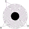
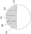
FIG. 3 is a cross-sectional view taken at A-A of FIG. 2;
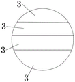
FIG. 4 is a cross-sectional view taken at B-B of FIG. 2;
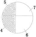
FIG. 5 is a cross-sectional view taken at C-C of FIG. 2;
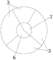
FIG. 6 is a cross-sectional view taken at D-D of FIG. 2;
FIG. 7 is a schematic structural view of an evaporator body according to embodiment 2 of the present invention;
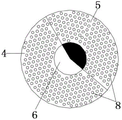
FIG. 8 is a cross-sectional view taken at E-E of FIG. 7;
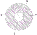
FIG. 9 is a cross-sectional view at F-F in FIG. 7;
FIG. 10 is a cross-sectional view taken at G-G of FIG. 7;
FIG. 11 is a cross-sectional view taken at H-H in FIG. 7;
the symbols in the drawings illustrate that:
the shell 1, feeding chamber 2, hydrops jar 3, first main heating chamber 4, the main heating chamber 5 of second, first main vapor-liquid separation room 6, the main vapor-liquid separation room 7 of second, heating pipe 8, steam inlet 9, MVR compressor 10, condenser export 11, condensation vapor-liquid separator 12.
Detailed Description
The invention will now be described in further detail with reference to the accompanying drawings. It is noted that the present invention is applicable to a variety of multi-effect evaporators, and to rising film, falling film or rising and falling film integrated evaporators. For reasons of space, the following description will be made in detail by taking as an example an evaporator in which the number of the main heating chambers is only two, and each of the main heating chambers includes two sub-heating chambers.
Example 1
As shown in fig. 1 to 6, a series-parallel connection integrated multi-effect evaporator comprises an evaporator body, wherein the evaporator body comprises a shell 1, four feeding cavities 2 arranged at the top of the shell, four liquid accumulation cylinders 3 arranged at the bottom of the shell 1 and corresponding to the feeding cavities 2 one by one, and a heater arranged in the shell 1;
the heating device is characterized in that two main heating cavities arranged along the length direction of the shell 1 and two main vapor-liquid separation chambers arranged along the length direction of the shell are arranged in the shell 1, the two main heating cavities are respectively a first main heating cavity 4 and a second main heating cavity 5, the two main vapor-liquid separation chambers are respectively a first main vapor-liquid separation chamber 6 and a second main vapor-liquid separation chamber 7, the first main vapor-liquid separation chamber 6 is arranged in the first main heating cavity 4, the second main vapor-liquid separation chamber 7 is arranged in the second main heating cavity 5, and the first main heating cavity 4 is connected with the second main heating cavity 5 in series through the first main vapor-liquid separation chamber 6; namely, the secondary steam generated after the material is heated by the steam in the first main heating cavity 4 is conveyed into the second main heating cavity 5 through the first main steam-liquid separation chamber 6 to heat the material, so that the materials are connected in series;
the first main heating cavity 4 comprises two auxiliary heating cavities, the second main heating cavity 5 also comprises two auxiliary heating cavities, at the moment, the whole equipment has four auxiliary heating cavities in total, the four auxiliary heating cavities correspond to the four feeding cavities 2 in a one-to-one manner, the two auxiliary heating cavities in the first main heating cavity 4 are communicated with each other, and the two auxiliary heating cavities in the second main heating cavity 5 are also communicated with each other, so that the two auxiliary heating cavities in the same main heating cavity can be kept in the same air pressure and the same heating temperature, namely, a parallel mode is formed;
the main vapor-liquid separation chamber 5 comprises two auxiliary vapor-liquid separation chambers 7, the auxiliary vapor-liquid separation chambers 7 correspond to the auxiliary heating cavities 6 one by one, and the auxiliary vapor-liquid separation chambers 7 in the same main vapor-liquid separation chamber 5 are communicated;
a distributing device is arranged in the feeding cavity 2, the adjacent liquid accumulating cylinders 3 are communicated through a material transferring pipeline, so that the four liquid accumulating cylinders 3 are connected in series, when in use, the first liquid accumulating cylinder adopts the material with the external original concentration as the raw material supplement, the next liquid accumulating cylinder connected in series with the liquid accumulating cylinder adopts the material in the first liquid accumulating cylinder as the raw material supplement, and so on, thereby leading the materials in the four liquid accumulating cylinders which are connected in series to form a certain concentration difference, further achieving the effect of multi-stage concentration, the liquid accumulation cylinder 3 is connected with the corresponding feeding cavity 2 through a conveying pipeline, a conveying pump is arranged on the conveying pipeline, the feeding cavity 2 adopts the material in the liquid accumulation cylinder corresponding to the feeding cavity as the raw material for adding, the feeding concentrations in the four feeding cavities 2 form a concentration difference, and then the parallel heating concentration effect among materials with different concentrations in the main heating cavity is realized;
the heater comprises a plurality of heating pipes 8 which are uniformly distributed in four auxiliary heating cavities, the heating pipes 8 are one of in-line heating pipes, curved heating pipes or plate-type heat exchangers, one end of each heating pipe 8 is communicated with the feeding cavity 2, and the other end of each heating pipe 8 is communicated with the liquid accumulating cylinder 3; a guide plate capable of preventing the material from washing to generate disturbance foam is arranged at the lower end of the heating pipe 8, one end of the guide plate is connected with the heating pipe 8, and the other end of the guide plate is abutted against the inner wall of the liquid accumulation cylinder;
a steam inlet 9 is arranged at one side of the top of the shell 1 corresponding to the first main heating cavity 4, the steam inlet 9 is externally connected with an MVR compressor 10, a condenser outlet 11 is arranged at one side of the bottom of the shell 1 corresponding to the first main heating cavity 4, and the condenser outlet 11 is externally connected with a condensed water vapor-liquid separator 12; the top of the second main vapor-liquid separation chamber 7 is communicated with an MVR compressor 7 outside the shell 1, so that the vapor separated from the second main vapor-liquid separation chamber 7 enters the MVR compressor 7 for recycling, and the effect of saving energy is achieved;
the sum of the volumes of the inner pipes of all the heating pipes 8 in the heater accounts for 1/12-1/6 of the total volume of the interior of the shell 1;
the four dropsy cavities are arranged at the positions below the bottoms of the first main heating cavity and the second main heating cavity respectively, wherein two dropsy cavities are arranged in one group.
Example 2
As shown in fig. 7 to 11, the present embodiment is different from embodiment 1 in that: first main vapour-liquid separation chamber 6 sets up 4 outside first main heating chamber, second main vapour-liquid separation chamber 7 sets up outside second main heating chamber 5, just first main heating chamber 4 and second main heating chamber 5 set up in the inside one side of shell 1 outward, and first main vapour-liquid separation chamber 6 and second main vapour-liquid separation chamber 7 set up in the inside opposite side of shell 1, and this moment four hydrops chambeies use two to set up respectively in the below position of first main vapour-liquid separation chamber 6 and second main vapour-liquid separation chamber 7 as a set of.
Finally, it should be noted that: these embodiments are merely illustrative of the present invention and do not limit the scope of the present invention. In addition, other variations and modifications will be apparent to persons skilled in the art based on the foregoing description. And are neither required nor exhaustive of all embodiments. And obvious variations or modifications of the invention may be made without departing from the scope of the invention.
Claims (7)
1. The utility model provides a many effect evaporators of series-parallel connection integral type, includes the evaporimeter body, its characterized in that: the evaporator body comprises a shell, a plurality of feeding cavities arranged at one end of the shell, a plurality of liquid accumulation cylinders arranged at the other end of the shell and corresponding to the feeding cavities one by one, and a heater arranged in the shell, wherein a plurality of main heating cavities arranged along the length direction of the shell and a plurality of main vapor-liquid separation chambers arranged along the length direction of the shell are arranged in the shell, the main heating cavities and the main vapor-liquid separation chambers are in one-to-one correspondence, the plurality of main heating cavities are connected in series through the corresponding main vapor-liquid separation chambers, the main heating cavities comprise a plurality of auxiliary heating cavities, the auxiliary heating cavities and the feeding cavities are in one-to-one correspondence, a plurality of auxiliary heating cavities in the same main heating cavity are communicated, the main vapor-liquid separation chambers comprise a plurality of auxiliary vapor-liquid separation chambers, the auxiliary vapor-liquid separation chambers and the auxiliary heating cavities are in one-to one correspondence, and the auxiliary vapor-liquid separation chambers in the, the feeding cavity is internally provided with a distributing device, a plurality of liquid accumulating cylinders are sequentially communicated through a material transferring pipeline, the liquid accumulating cylinders are connected with the corresponding feeding cavity through a conveying pipeline, the conveying pipeline is provided with a conveying pump, the heater comprises a plurality of heating pipes which are uniformly distributed in the auxiliary heating cavity, one end of each heating pipe is communicated with the feeding cavity, and the other end of each heating pipe is communicated with the liquid accumulating cylinder.
2. The series-parallel integrated multi-effect evaporator of claim 1, wherein: the quantity of main heating chamber, the quantity of main vapour-liquid separation room are more than 2 respectively, the quantity of vice heating chamber in each main heating chamber, the quantity of vice vapour-liquid separation room in each main vapour-liquid separation room are more than 1 respectively.
3. The series-parallel integrated multi-effect evaporator of claim 1, wherein: one end of the heating pipe close to the liquid accumulation cylinder is provided with a guide plate capable of avoiding the material from scouring to generate disturbance foam, one end of the guide plate is connected to the heating pipe, and the other end of the guide plate is abutted to the inner wall of the liquid accumulation cylinder.
4. The series-parallel integrated multi-effect evaporator of claim 1, wherein: the main vapor-liquid separation chamber is arranged in the main heating cavity.
5. The series-parallel integrated multi-effect evaporator of claim 1, wherein: the main vapor-liquid separation chamber is arranged outside the main heating cavity and is arranged in parallel with the main heating cavity.
6. The series-parallel integrated multi-effect evaporator as set forth in any one of claims 1-5, wherein: the heating pipe is an in-line heating pipe, a curve-shaped heating pipe or a plate type heat exchanger.
7. The series-parallel integrated multi-effect evaporator as set forth in any one of claims 6, wherein: the sum of the volumes of the inner pipes of all the heating pipes in the heater accounts for 1/12-1/6 of the total volume of the interior of the shell.
Priority Applications (1)
| Application Number | Priority Date | Filing Date | Title |
|---|---|---|---|
| CN201711075344.9A CN107638708B (en) | 2017-11-06 | 2017-11-06 | Series-parallel connection integrated multi-effect evaporator |
Applications Claiming Priority (1)
| Application Number | Priority Date | Filing Date | Title |
|---|---|---|---|
| CN201711075344.9A CN107638708B (en) | 2017-11-06 | 2017-11-06 | Series-parallel connection integrated multi-effect evaporator |
Publications (2)
| Publication Number | Publication Date |
|---|---|
| CN107638708A CN107638708A (en) | 2018-01-30 |
| CN107638708B true CN107638708B (en) | 2021-06-01 |
Family
ID=61125255
Family Applications (1)
| Application Number | Title | Priority Date | Filing Date |
|---|---|---|---|
| CN201711075344.9A Expired - Fee Related CN107638708B (en) | 2017-11-06 | 2017-11-06 | Series-parallel connection integrated multi-effect evaporator |
Country Status (1)
| Country | Link |
|---|---|
| CN (1) | CN107638708B (en) |
Families Citing this family (2)
| Publication number | Priority date | Publication date | Assignee | Title |
|---|---|---|---|---|
| CN110075557A (en) * | 2019-06-04 | 2019-08-02 | 吉林惠利现代轻工装备有限公司 | A kind of multistage suitching type feed liquid method of evaporating and device |
| CN113577802A (en) * | 2021-08-19 | 2021-11-02 | 南京金日轻工科技发展有限公司 | Extensible energy-saving evaporator |
Citations (6)
| Publication number | Priority date | Publication date | Assignee | Title |
|---|---|---|---|---|
| CN2179187Y (en) * | 1993-09-19 | 1994-10-12 | 李春崇 | Falling-film evaporator |
| CN102553274A (en) * | 2012-03-11 | 2012-07-11 | 甘肃蓝科石化高新装备股份有限公司 | Tubular evaporator device with mechanical steam compressor |
| CN102657958A (en) * | 2012-04-21 | 2012-09-12 | 深圳市汇清科技有限公司 | Ultrafiltration membrane deaerating unit |
| CN102989181A (en) * | 2012-12-17 | 2013-03-27 | 李锦龙 | Compound type monomer multi-effect steam mechanical recompression evaporator |
| CN104667550A (en) * | 2015-02-09 | 2015-06-03 | 南京工业大学 | MVR continuous evaporation system |
| CN205293453U (en) * | 2015-12-22 | 2016-06-08 | 广州立白企业集团有限公司 | Liquid feeding guiding device |
-
2017
- 2017-11-06 CN CN201711075344.9A patent/CN107638708B/en not_active Expired - Fee Related
Patent Citations (6)
| Publication number | Priority date | Publication date | Assignee | Title |
|---|---|---|---|---|
| CN2179187Y (en) * | 1993-09-19 | 1994-10-12 | 李春崇 | Falling-film evaporator |
| CN102553274A (en) * | 2012-03-11 | 2012-07-11 | 甘肃蓝科石化高新装备股份有限公司 | Tubular evaporator device with mechanical steam compressor |
| CN102657958A (en) * | 2012-04-21 | 2012-09-12 | 深圳市汇清科技有限公司 | Ultrafiltration membrane deaerating unit |
| CN102989181A (en) * | 2012-12-17 | 2013-03-27 | 李锦龙 | Compound type monomer multi-effect steam mechanical recompression evaporator |
| CN104667550A (en) * | 2015-02-09 | 2015-06-03 | 南京工业大学 | MVR continuous evaporation system |
| CN205293453U (en) * | 2015-12-22 | 2016-06-08 | 广州立白企业集团有限公司 | Liquid feeding guiding device |
Also Published As
| Publication number | Publication date |
|---|---|
| CN107638708A (en) | 2018-01-30 |
Similar Documents
| Publication | Publication Date | Title |
|---|---|---|
| CN204034294U (en) | The board-like forced-circulation evaporator of novel triple effect | |
| CN206304378U (en) | The energy-conservation MVR evaporators that a kind of vapor recompression is utilized | |
| CN107638708B (en) | Series-parallel connection integrated multi-effect evaporator | |
| CN105664514B (en) | Horizontal MVC evaporators | |
| CN219735652U (en) | Supercritical CO2 refrigeration cycle coupling high-salt water evaporation zero-emission system | |
| CN107098419A (en) | A kind of solar airconditioning seawater desalination system | |
| CN202538618U (en) | Air pretreatment device capable of utilizing waste heat | |
| CN104329837B (en) | A kind of enhanced heat exchange heat pump | |
| CN108159717B (en) | Internal rotation heating circulation evaporator and system for treating salt-containing wastewater by using same | |
| CN105645491A (en) | Water purification system and process | |
| CN106474756A (en) | A kind of energy-efficient MVR vaporising device | |
| CN109939454A (en) | A kind of heat pump vacuum concentration system | |
| CN104027990A (en) | Mechanical steam recompression evaporator | |
| CN210751327U (en) | Multi-effect evaporator | |
| CN212523051U (en) | Seven-effect tube plate combined falling film evaporation system for concentrating sodium aluminate solution | |
| CN209828291U (en) | Heat pump vacuum concentration system | |
| CN112657219A (en) | Evaporation concentration system and evaporation concentration method | |
| CN202393258U (en) | Vertical indirect condenser applicable to vacuum evaporation and crystallizing system | |
| CN110882553A (en) | Low-temperature vacuum evaporator | |
| CN213466793U (en) | Glycerol concentration device | |
| CN205461082U (en) | Horizontal MVC evaporimeter | |
| CN205730417U (en) | A kind of MVR multi-stage evaporation unit | |
| CN110420469A (en) | Evaporation concentration system | |
| CN217593859U (en) | Double-effect evaporation concentration system | |
| CN214232802U (en) | Evaporation concentration system |
Legal Events
| Date | Code | Title | Description |
|---|---|---|---|
| PB01 | Publication | ||
| PB01 | Publication | ||
| SE01 | Entry into force of request for substantive examination | ||
| SE01 | Entry into force of request for substantive examination | ||
| GR01 | Patent grant | ||
| GR01 | Patent grant | ||
| CF01 | Termination of patent right due to non-payment of annual fee |
Granted publication date: 20210601 |
|
| CF01 | Termination of patent right due to non-payment of annual fee |