CN107596530B - Medical component with microstructures for humidification and condensate management - Google Patents
Medical component with microstructures for humidification and condensate management Download PDFInfo
- Publication number
- CN107596530B CN107596530B CN201710470785.2A CN201710470785A CN107596530B CN 107596530 B CN107596530 B CN 107596530B CN 201710470785 A CN201710470785 A CN 201710470785A CN 107596530 B CN107596530 B CN 107596530B
- Authority
- CN
- China
- Prior art keywords
- microstructures
- patient interface
- tube
- mask
- microstructure
- Prior art date
- Legal status (The legal status is an assumption and is not a legal conclusion. Google has not performed a legal analysis and makes no representation as to the accuracy of the status listed.)
- Active
Links
- 230000029058 respiratory gaseous exchange Effects 0.000 claims abstract description 13
- 239000000463 material Substances 0.000 claims description 41
- 238000010438 heat treatment Methods 0.000 claims description 24
- 229920000642 polymer Polymers 0.000 claims description 17
- 230000001788 irregular Effects 0.000 claims description 14
- 239000000758 substrate Substances 0.000 claims description 13
- 239000000654 additive Substances 0.000 claims description 11
- 230000000996 additive effect Effects 0.000 claims description 7
- 238000004891 communication Methods 0.000 claims description 5
- 238000002644 respiratory therapy Methods 0.000 claims description 4
- 239000013078 crystal Substances 0.000 claims description 2
- 239000011159 matrix material Substances 0.000 claims description 2
- 238000004381 surface treatment Methods 0.000 claims description 2
- XLYOFNOQVPJJNP-UHFFFAOYSA-N water Substances O XLYOFNOQVPJJNP-UHFFFAOYSA-N 0.000 abstract description 53
- 230000003434 inspiratory effect Effects 0.000 abstract description 9
- 239000000523 sample Substances 0.000 abstract description 9
- 241001631457 Cannula Species 0.000 abstract description 3
- 239000007788 liquid Substances 0.000 description 75
- 230000008020 evaporation Effects 0.000 description 40
- 238000001704 evaporation Methods 0.000 description 40
- 239000007789 gas Substances 0.000 description 39
- 239000003570 air Substances 0.000 description 35
- 238000000034 method Methods 0.000 description 25
- 230000001965 increasing effect Effects 0.000 description 16
- 239000004094 surface-active agent Substances 0.000 description 16
- 239000003795 chemical substances by application Substances 0.000 description 15
- 238000004519 manufacturing process Methods 0.000 description 14
- 229910052751 metal Inorganic materials 0.000 description 12
- 239000002184 metal Substances 0.000 description 12
- 238000001125 extrusion Methods 0.000 description 10
- 238000003892 spreading Methods 0.000 description 10
- 230000007480 spreading Effects 0.000 description 10
- 239000004594 Masterbatch (MB) Substances 0.000 description 7
- 238000000576 coating method Methods 0.000 description 7
- 238000003475 lamination Methods 0.000 description 7
- 239000003607 modifier Substances 0.000 description 7
- ZMXDDKWLCZADIW-UHFFFAOYSA-N N,N-Dimethylformamide Chemical compound CN(C)C=O ZMXDDKWLCZADIW-UHFFFAOYSA-N 0.000 description 6
- 229920003023 plastic Polymers 0.000 description 6
- 239000004033 plastic Substances 0.000 description 6
- 229910052782 aluminium Inorganic materials 0.000 description 5
- XAGFODPZIPBFFR-UHFFFAOYSA-N aluminium Chemical compound [Al] XAGFODPZIPBFFR-UHFFFAOYSA-N 0.000 description 5
- 239000011248 coating agent Substances 0.000 description 5
- 238000009833 condensation Methods 0.000 description 5
- 230000005494 condensation Effects 0.000 description 5
- 230000005484 gravity Effects 0.000 description 5
- -1 polypropylene Polymers 0.000 description 5
- 230000008569 process Effects 0.000 description 5
- 239000007787 solid Substances 0.000 description 5
- 239000002904 solvent Substances 0.000 description 5
- 238000003860 storage Methods 0.000 description 5
- VBICKXHEKHSIBG-UHFFFAOYSA-N 1-monostearoylglycerol Chemical compound CCCCCCCCCCCCCCCCCC(=O)OCC(O)CO VBICKXHEKHSIBG-UHFFFAOYSA-N 0.000 description 4
- WYURNTSHIVDZCO-UHFFFAOYSA-N Tetrahydrofuran Chemical compound C1CCOC1 WYURNTSHIVDZCO-UHFFFAOYSA-N 0.000 description 4
- 230000015572 biosynthetic process Effects 0.000 description 4
- 239000011521 glass Substances 0.000 description 4
- 230000003993 interaction Effects 0.000 description 4
- 239000000203 mixture Substances 0.000 description 4
- 239000013500 performance material Substances 0.000 description 4
- 239000000126 substance Substances 0.000 description 4
- 238000012546 transfer Methods 0.000 description 4
- RYGMFSIKBFXOCR-UHFFFAOYSA-N Copper Chemical compound [Cu] RYGMFSIKBFXOCR-UHFFFAOYSA-N 0.000 description 3
- 230000009471 action Effects 0.000 description 3
- 230000008901 benefit Effects 0.000 description 3
- 229910052802 copper Inorganic materials 0.000 description 3
- 239000010949 copper Substances 0.000 description 3
- 238000005259 measurement Methods 0.000 description 3
- 239000012528 membrane Substances 0.000 description 3
- 238000002156 mixing Methods 0.000 description 3
- 230000003746 surface roughness Effects 0.000 description 3
- 238000012876 topography Methods 0.000 description 3
- 206010002091 Anaesthesia Diseases 0.000 description 2
- 229910001369 Brass Inorganic materials 0.000 description 2
- 239000002202 Polyethylene glycol Substances 0.000 description 2
- 239000004743 Polypropylene Substances 0.000 description 2
- 239000012080 ambient air Substances 0.000 description 2
- 230000037005 anaesthesia Effects 0.000 description 2
- 239000011324 bead Substances 0.000 description 2
- 239000010951 brass Substances 0.000 description 2
- 239000003093 cationic surfactant Substances 0.000 description 2
- 230000000295 complement effect Effects 0.000 description 2
- 238000010276 construction Methods 0.000 description 2
- 238000013461 design Methods 0.000 description 2
- 238000010586 diagram Methods 0.000 description 2
- 239000006185 dispersion Substances 0.000 description 2
- 238000004049 embossing Methods 0.000 description 2
- 230000002708 enhancing effect Effects 0.000 description 2
- 230000001815 facial effect Effects 0.000 description 2
- 239000012530 fluid Substances 0.000 description 2
- 239000011888 foil Substances 0.000 description 2
- 230000006870 function Effects 0.000 description 2
- 230000001976 improved effect Effects 0.000 description 2
- 229920000092 linear low density polyethylene Polymers 0.000 description 2
- 239000004707 linear low-density polyethylene Substances 0.000 description 2
- 229920001684 low density polyethylene Polymers 0.000 description 2
- 239000004702 low-density polyethylene Substances 0.000 description 2
- 239000000155 melt Substances 0.000 description 2
- 150000002739 metals Chemical class 0.000 description 2
- 238000002715 modification method Methods 0.000 description 2
- 239000002736 nonionic surfactant Substances 0.000 description 2
- 229920001223 polyethylene glycol Polymers 0.000 description 2
- 229920000139 polyethylene terephthalate Polymers 0.000 description 2
- 239000005020 polyethylene terephthalate Substances 0.000 description 2
- 229920001155 polypropylene Polymers 0.000 description 2
- 230000005855 radiation Effects 0.000 description 2
- 230000004044 response Effects 0.000 description 2
- YLQBMQCUIZJEEH-UHFFFAOYSA-N tetrahydrofuran Natural products C=1C=COC=1 YLQBMQCUIZJEEH-UHFFFAOYSA-N 0.000 description 2
- 238000002560 therapeutic procedure Methods 0.000 description 2
- 230000007704 transition Effects 0.000 description 2
- JNYAEWCLZODPBN-JGWLITMVSA-N (2r,3r,4s)-2-[(1r)-1,2-dihydroxyethyl]oxolane-3,4-diol Chemical class OC[C@@H](O)[C@H]1OC[C@H](O)[C@H]1O JNYAEWCLZODPBN-JGWLITMVSA-N 0.000 description 1
- ZZNDQCACFUJAKJ-UHFFFAOYSA-N 1-phenyltridecan-1-one Chemical compound CCCCCCCCCCCCC(=O)C1=CC=CC=C1 ZZNDQCACFUJAKJ-UHFFFAOYSA-N 0.000 description 1
- 229920008132 Arnitel® VT3108 Polymers 0.000 description 1
- 241000579895 Chlorostilbon Species 0.000 description 1
- 229920010126 Linear Low Density Polyethylene (LLDPE) Polymers 0.000 description 1
- 239000004425 Makrolon Substances 0.000 description 1
- CBENFWSGALASAD-UHFFFAOYSA-N Ozone Chemical compound [O-][O+]=O CBENFWSGALASAD-UHFFFAOYSA-N 0.000 description 1
- 229920012485 Plasticized Polyvinyl chloride Polymers 0.000 description 1
- 229920000034 Plastomer Polymers 0.000 description 1
- 239000004952 Polyamide Substances 0.000 description 1
- 229920002614 Polyether block amide Polymers 0.000 description 1
- 239000004721 Polyphenylene oxide Substances 0.000 description 1
- XUIMIQQOPSSXEZ-UHFFFAOYSA-N Silicon Chemical group [Si] XUIMIQQOPSSXEZ-UHFFFAOYSA-N 0.000 description 1
- 210000000683 abdominal cavity Anatomy 0.000 description 1
- 230000002745 absorbent Effects 0.000 description 1
- 239000002250 absorbent Substances 0.000 description 1
- 230000001133 acceleration Effects 0.000 description 1
- 239000002253 acid Substances 0.000 description 1
- 150000007513 acids Chemical class 0.000 description 1
- NIXOWILDQLNWCW-UHFFFAOYSA-N acrylic acid group Chemical group C(C=C)(=O)O NIXOWILDQLNWCW-UHFFFAOYSA-N 0.000 description 1
- 239000004480 active ingredient Substances 0.000 description 1
- 239000000853 adhesive Substances 0.000 description 1
- 238000004026 adhesive bonding Methods 0.000 description 1
- 230000001070 adhesive effect Effects 0.000 description 1
- 150000001412 amines Chemical class 0.000 description 1
- 125000000129 anionic group Chemical group 0.000 description 1
- 239000003945 anionic surfactant Substances 0.000 description 1
- 239000002518 antifoaming agent Substances 0.000 description 1
- 210000003050 axon Anatomy 0.000 description 1
- 230000036760 body temperature Effects 0.000 description 1
- 238000005266 casting Methods 0.000 description 1
- 125000002091 cationic group Chemical group 0.000 description 1
- 229910010293 ceramic material Inorganic materials 0.000 description 1
- 230000008859 change Effects 0.000 description 1
- 229920001940 conductive polymer Polymers 0.000 description 1
- 239000004020 conductor Substances 0.000 description 1
- 238000011513 continuous positive airway pressure therapy Methods 0.000 description 1
- 229920001577 copolymer Polymers 0.000 description 1
- 238000005520 cutting process Methods 0.000 description 1
- 230000018044 dehydration Effects 0.000 description 1
- 238000006297 dehydration reaction Methods 0.000 description 1
- 230000002939 deleterious effect Effects 0.000 description 1
- 150000005690 diesters Chemical class 0.000 description 1
- 238000007599 discharging Methods 0.000 description 1
- KPUWHANPEXNPJT-UHFFFAOYSA-N disiloxane Chemical class [SiH3]O[SiH3] KPUWHANPEXNPJT-UHFFFAOYSA-N 0.000 description 1
- 230000000694 effects Effects 0.000 description 1
- 238000010894 electron beam technology Methods 0.000 description 1
- 230000008030 elimination Effects 0.000 description 1
- 238000003379 elimination reaction Methods 0.000 description 1
- 229910052876 emerald Inorganic materials 0.000 description 1
- 239000010976 emerald Substances 0.000 description 1
- 229920006351 engineering plastic Polymers 0.000 description 1
- 239000005038 ethylene vinyl acetate Substances 0.000 description 1
- 150000002191 fatty alcohols Chemical class 0.000 description 1
- 239000002223 garnet Substances 0.000 description 1
- 229940075507 glyceryl monostearate Drugs 0.000 description 1
- PCHJSUWPFVWCPO-UHFFFAOYSA-N gold Chemical compound [Au] PCHJSUWPFVWCPO-UHFFFAOYSA-N 0.000 description 1
- 239000010931 gold Substances 0.000 description 1
- 229910052737 gold Inorganic materials 0.000 description 1
- GPRLSGONYQIRFK-UHFFFAOYSA-N hydron Chemical compound [H+] GPRLSGONYQIRFK-UHFFFAOYSA-N 0.000 description 1
- 229920001477 hydrophilic polymer Polymers 0.000 description 1
- 230000006872 improvement Effects 0.000 description 1
- 238000010348 incorporation Methods 0.000 description 1
- 230000001939 inductive effect Effects 0.000 description 1
- 239000004615 ingredient Substances 0.000 description 1
- 238000001746 injection moulding Methods 0.000 description 1
- 238000009413 insulation Methods 0.000 description 1
- 238000010884 ion-beam technique Methods 0.000 description 1
- 238000005304 joining Methods 0.000 description 1
- 238000002032 lab-on-a-chip Methods 0.000 description 1
- 238000003754 machining Methods 0.000 description 1
- 230000007246 mechanism Effects 0.000 description 1
- 239000007769 metal material Substances 0.000 description 1
- 238000003801 milling Methods 0.000 description 1
- 230000004048 modification Effects 0.000 description 1
- 238000012986 modification Methods 0.000 description 1
- 239000002991 molded plastic Substances 0.000 description 1
- 239000001788 mono and diglycerides of fatty acids Substances 0.000 description 1
- 229920000847 nonoxynol Polymers 0.000 description 1
- 230000006911 nucleation Effects 0.000 description 1
- 238000010899 nucleation Methods 0.000 description 1
- 230000003287 optical effect Effects 0.000 description 1
- 230000003647 oxidation Effects 0.000 description 1
- 238000007254 oxidation reaction Methods 0.000 description 1
- 239000002245 particle Substances 0.000 description 1
- 239000008188 pellet Substances 0.000 description 1
- 230000002186 photoactivation Effects 0.000 description 1
- 238000000053 physical method Methods 0.000 description 1
- 239000000049 pigment Substances 0.000 description 1
- 229920003229 poly(methyl methacrylate) Polymers 0.000 description 1
- 229920002647 polyamide Polymers 0.000 description 1
- 229920000515 polycarbonate Polymers 0.000 description 1
- 229920000728 polyester Polymers 0.000 description 1
- 229920000570 polyether Polymers 0.000 description 1
- 229920002338 polyhydroxyethylmethacrylate Polymers 0.000 description 1
- 239000004926 polymethyl methacrylate Substances 0.000 description 1
- 229920000098 polyolefin Polymers 0.000 description 1
- 229920002635 polyurethane Polymers 0.000 description 1
- 239000004814 polyurethane Substances 0.000 description 1
- 239000004800 polyvinyl chloride Substances 0.000 description 1
- 230000002980 postoperative effect Effects 0.000 description 1
- 238000011084 recovery Methods 0.000 description 1
- 230000009467 reduction Effects 0.000 description 1
- 230000002787 reinforcement Effects 0.000 description 1
- 230000003014 reinforcing effect Effects 0.000 description 1
- 230000000241 respiratory effect Effects 0.000 description 1
- 230000000630 rising effect Effects 0.000 description 1
- 229920006395 saturated elastomer Polymers 0.000 description 1
- 238000007789 sealing Methods 0.000 description 1
- 238000000926 separation method Methods 0.000 description 1
- 229920002545 silicone oil Polymers 0.000 description 1
- 229910052708 sodium Inorganic materials 0.000 description 1
- 239000011734 sodium Substances 0.000 description 1
- 230000003381 solubilizing effect Effects 0.000 description 1
- 238000001179 sorption measurement Methods 0.000 description 1
- 230000003068 static effect Effects 0.000 description 1
- 238000010998 test method Methods 0.000 description 1
- 210000001835 viscera Anatomy 0.000 description 1
- 238000003466 welding Methods 0.000 description 1
- 238000009736 wetting Methods 0.000 description 1
- 239000000080 wetting agent Substances 0.000 description 1
- 238000004804 winding Methods 0.000 description 1
Images


Classifications
-
- A—HUMAN NECESSITIES
- A61—MEDICAL OR VETERINARY SCIENCE; HYGIENE
- A61M—DEVICES FOR INTRODUCING MEDIA INTO, OR ONTO, THE BODY; DEVICES FOR TRANSDUCING BODY MEDIA OR FOR TAKING MEDIA FROM THE BODY; DEVICES FOR PRODUCING OR ENDING SLEEP OR STUPOR
- A61M16/00—Devices for influencing the respiratory system of patients by gas treatment, e.g. mouth-to-mouth respiration; Tracheal tubes
- A61M16/06—Respiratory or anaesthetic masks
-
- A—HUMAN NECESSITIES
- A61—MEDICAL OR VETERINARY SCIENCE; HYGIENE
- A61M—DEVICES FOR INTRODUCING MEDIA INTO, OR ONTO, THE BODY; DEVICES FOR TRANSDUCING BODY MEDIA OR FOR TAKING MEDIA FROM THE BODY; DEVICES FOR PRODUCING OR ENDING SLEEP OR STUPOR
- A61M16/00—Devices for influencing the respiratory system of patients by gas treatment, e.g. mouth-to-mouth respiration; Tracheal tubes
- A61M16/10—Preparation of respiratory gases or vapours
- A61M16/1075—Preparation of respiratory gases or vapours by influencing the temperature
- A61M16/109—Preparation of respiratory gases or vapours by influencing the temperature the humidifying liquid or the beneficial agent
-
- A—HUMAN NECESSITIES
- A61—MEDICAL OR VETERINARY SCIENCE; HYGIENE
- A61M—DEVICES FOR INTRODUCING MEDIA INTO, OR ONTO, THE BODY; DEVICES FOR TRANSDUCING BODY MEDIA OR FOR TAKING MEDIA FROM THE BODY; DEVICES FOR PRODUCING OR ENDING SLEEP OR STUPOR
- A61M16/00—Devices for influencing the respiratory system of patients by gas treatment, e.g. mouth-to-mouth respiration; Tracheal tubes
- A61M16/10—Preparation of respiratory gases or vapours
- A61M16/1075—Preparation of respiratory gases or vapours by influencing the temperature
- A61M16/1095—Preparation of respiratory gases or vapours by influencing the temperature in the connecting tubes
-
- A—HUMAN NECESSITIES
- A61—MEDICAL OR VETERINARY SCIENCE; HYGIENE
- A61M—DEVICES FOR INTRODUCING MEDIA INTO, OR ONTO, THE BODY; DEVICES FOR TRANSDUCING BODY MEDIA OR FOR TAKING MEDIA FROM THE BODY; DEVICES FOR PRODUCING OR ENDING SLEEP OR STUPOR
- A61M16/00—Devices for influencing the respiratory system of patients by gas treatment, e.g. mouth-to-mouth respiration; Tracheal tubes
- A61M16/10—Preparation of respiratory gases or vapours
- A61M16/14—Preparation of respiratory gases or vapours by mixing different fluids, one of them being in a liquid phase
- A61M16/16—Devices to humidify the respiration air
-
- A—HUMAN NECESSITIES
- A61—MEDICAL OR VETERINARY SCIENCE; HYGIENE
- A61M—DEVICES FOR INTRODUCING MEDIA INTO, OR ONTO, THE BODY; DEVICES FOR TRANSDUCING BODY MEDIA OR FOR TAKING MEDIA FROM THE BODY; DEVICES FOR PRODUCING OR ENDING SLEEP OR STUPOR
- A61M11/00—Sprayers or atomisers specially adapted for therapeutic purposes
- A61M11/04—Sprayers or atomisers specially adapted for therapeutic purposes operated by the vapour pressure of the liquid to be sprayed or atomised
- A61M11/041—Sprayers or atomisers specially adapted for therapeutic purposes operated by the vapour pressure of the liquid to be sprayed or atomised using heaters
- A61M11/042—Sprayers or atomisers specially adapted for therapeutic purposes operated by the vapour pressure of the liquid to be sprayed or atomised using heaters electrical
-
- A—HUMAN NECESSITIES
- A61—MEDICAL OR VETERINARY SCIENCE; HYGIENE
- A61M—DEVICES FOR INTRODUCING MEDIA INTO, OR ONTO, THE BODY; DEVICES FOR TRANSDUCING BODY MEDIA OR FOR TAKING MEDIA FROM THE BODY; DEVICES FOR PRODUCING OR ENDING SLEEP OR STUPOR
- A61M16/00—Devices for influencing the respiratory system of patients by gas treatment, e.g. mouth-to-mouth respiration; Tracheal tubes
- A61M16/0057—Pumps therefor
- A61M16/0066—Blowers or centrifugal pumps
- A61M16/0069—Blowers or centrifugal pumps the speed thereof being controlled by respiratory parameters, e.g. by inhalation
-
- A—HUMAN NECESSITIES
- A61—MEDICAL OR VETERINARY SCIENCE; HYGIENE
- A61M—DEVICES FOR INTRODUCING MEDIA INTO, OR ONTO, THE BODY; DEVICES FOR TRANSDUCING BODY MEDIA OR FOR TAKING MEDIA FROM THE BODY; DEVICES FOR PRODUCING OR ENDING SLEEP OR STUPOR
- A61M16/00—Devices for influencing the respiratory system of patients by gas treatment, e.g. mouth-to-mouth respiration; Tracheal tubes
- A61M16/021—Devices for influencing the respiratory system of patients by gas treatment, e.g. mouth-to-mouth respiration; Tracheal tubes operated by electrical means
-
- A—HUMAN NECESSITIES
- A61—MEDICAL OR VETERINARY SCIENCE; HYGIENE
- A61M—DEVICES FOR INTRODUCING MEDIA INTO, OR ONTO, THE BODY; DEVICES FOR TRANSDUCING BODY MEDIA OR FOR TAKING MEDIA FROM THE BODY; DEVICES FOR PRODUCING OR ENDING SLEEP OR STUPOR
- A61M16/00—Devices for influencing the respiratory system of patients by gas treatment, e.g. mouth-to-mouth respiration; Tracheal tubes
- A61M16/08—Bellows; Connecting tubes ; Water traps; Patient circuits
- A61M16/0875—Connecting tubes
-
- A—HUMAN NECESSITIES
- A61—MEDICAL OR VETERINARY SCIENCE; HYGIENE
- A61M—DEVICES FOR INTRODUCING MEDIA INTO, OR ONTO, THE BODY; DEVICES FOR TRANSDUCING BODY MEDIA OR FOR TAKING MEDIA FROM THE BODY; DEVICES FOR PRODUCING OR ENDING SLEEP OR STUPOR
- A61M2205/00—General characteristics of the apparatus
- A61M2205/33—Controlling, regulating or measuring
- A61M2205/3368—Temperature
-
- A—HUMAN NECESSITIES
- A61—MEDICAL OR VETERINARY SCIENCE; HYGIENE
- A61M—DEVICES FOR INTRODUCING MEDIA INTO, OR ONTO, THE BODY; DEVICES FOR TRANSDUCING BODY MEDIA OR FOR TAKING MEDIA FROM THE BODY; DEVICES FOR PRODUCING OR ENDING SLEEP OR STUPOR
- A61M2205/00—General characteristics of the apparatus
- A61M2205/75—General characteristics of the apparatus with filters
- A61M2205/7527—General characteristics of the apparatus with filters liquophilic, hydrophilic
Abstract
A medical component having a microstructure for humidification and condensate management is disclosed. These components include microstructures for humidification and/or condensate management. The disclosed microstructures can be incorporated into a wide variety of components, including tubes (e.g., inspiratory and expiratory breathing tubes and other tubing between different elements of a breathing circuit, such as ventilators, humidifiers, filters, water traps, sample lines, connectors, gas analyzers, and the like), Y-connectors, conduit adapters, humidifiers, and patient interfaces (e.g., masks for covering the nose and face, nasal masks, cannulas, nasal pillows, and the like), floats, probes, and sensors in a wide variety of medical circuits.
Description
This application is a divisional application based on the invention with application number 201380042710.4, filing date 2013, 25/06, filed by fisher corp healthcare limited, entitled medical component with microstructure for humidification and condensate management.
Cross Reference to Related Applications
The present application claims the benefit of priority from U.S. provisional application No. 61/785,895 filed on 3/14/2013 and U.S. provisional application No. 61/664,069 filed on 6/25/2012, the entire contents of which are hereby incorporated by reference.
Technical Field
The present disclosure relates generally to components suitable for medical use, and more particularly to components suitable for providing humidified gas to and/or removing humidified gas from a patient, such as used in Positive Airway Pressure (PAP), ventilator, anesthesia, ventilator, and insufflation systems.
Background
In the medical circuit, different components are carried to and from the patient natural or artificially humidified gases. E.g. in PAP or assisted breathingIn some breathing circuits, such as the circuit described above, gas inhaled by a patient is delivered from a heater-humidifier to a patient interface, such as a mask, via an inhalation tube. As another example, the tube may be filled with a humidified gas (typically CO)2) Into the abdominal cavity in an insufflation circuit. This may help prevent "dehydration" of the patient's internal organs, and may reduce the amount of time required for post-operative recovery.
In these medical applications, the gases are preferably delivered under conditions having a humidity near the saturation level and at near body temperature (typically at a temperature between 33 ℃ and 37 ℃). Condensation or "rain out" may form on the interior surfaces of the components as the high humidity breathing gases cool. There remains a need for components for allowing improved moisture and condensate management in medical circuits. It is therefore an object of certain components and methods described herein to ameliorate one or more problems of prior art systems, or at least to provide the public with a useful choice.
Disclosure of Invention
Medical components having microstructures for humidification and/or condensate management and methods of making such components are disclosed herein in various embodiments.
In at least one embodiment, a component for use in a medical circuit includes a first region that contacts a liquid in use; a second region different from the first region; and a microstructured surface in communication with the first region and the second region and configured to wick liquid from the first region to the second region in use, wherein the microstructured surface comprises a substrate having an equilibrium contact angle of less than about pi/2 radians.
In various embodiments, the aforementioned components may have one, some, or all of the following characteristics, as well as characteristics described elsewhere in this disclosure.
The second zone may be exposed to a higher velocity of air in use and the first zone may be exposed to a lower velocity of air in use. The second zone may be configured to communicate with a heat source. The microstructured surface can be configured to communicate with a heat source. The microstructured surface may include substantially parallel microchannels. The microchannels may be substantially square. θ the critical contact angle of these microchannels may satisfy the following equation:

where X represents the aspect ratio of these square channels. The microchannels may be substantially v-shaped. The critical contact angle θ of these microchannels may satisfy the following equation:

wherein β represents the angle of the v-shape. The microstructured surface may comprise micropillars. The microcolumns may have substantially the same cross-sectional dimensions. At least some of the microcolumns may have a cross-sectional size different from that of other microcolumns.
In various embodiments, the aforementioned components may be incorporated into the mask. The mask may further include a discharge in communication with the second region.
In various embodiments, the aforementioned components may be incorporated into a conduit. The component may form at least a portion of an inner wall of the conduit. The component may be an insert in the lumen of the conduit. The wall of the conduit may be configured to communicate with a heat source.
In at least one embodiment, a component for use in a medical circuit includes a storage portion configured to hold a liquid; an evaporator portion adjacent the storage portion configured to facilitate evaporation of the liquid; and a microstructured surface configured to transfer liquid from the storage portion to the evaporator portion.
In various embodiments, the aforementioned components have one, some, or all of the following characteristics, as well as characteristics described elsewhere in this disclosure.
The evaporator section may be heatable. The microstructured surface can include microchannels having an aspect ratio that is lower proximate the storage portion and higher proximate the evaporator portion, the aspect ratio increasing along a gradient. The microstructured surface can include first microchannels extending substantially horizontally proximate the storage portion and second microchannels extending substantially vertically proximate the evaporator portion, wherein the first microchannels are configured to deliver liquid to the second microchannels.
In various embodiments, the aforementioned components may be incorporated into the mask.
In various embodiments, the aforementioned components may be incorporated in a chamber suitable for use with a humidifier unit. The member may form at least a portion of an inner wall of the chamber. The chamber may include a wall configured to be heated by a heater base of the humidifier unit. The chamber may include a wall configured to be heated by a heating member different from the humidifier unit. The chamber may further comprise an insulation arranged on or above at least the wall of the chamber near the evaporator section.
In various embodiments, the aforementioned components may be incorporated into a conduit. The microstructured surface can form at least a portion of an inner wall of the conduit. The microstructured surface may be disposed on an insert in the lumen of the tube. The wall of the conduit is configured to communicate with a heat source.
In at least one embodiment, a medical circuit component for use with humidified gases includes: a wall defining a space within the wall and wherein at least a portion of the wall comprises a surface comprising a plurality of microchannels within and on a substrate, the substrate having an outer surface with an equilibrium contact angle of less than about pi/2 radians, the microchannels being configured to wick, in use, liquid from a first region holding liquid water to a second region exposed to a flow of air to or from a patient, and the microchannels comprising first microchannels having side portions and floor portions lower than the outer surface of the substrate, and second microchannels having side portions higher than the outer surface of the substrate, wherein the side portions of the second microchannels are formed by ridges around or between the first microchannels.
In various embodiments, the aforementioned medical circuit may have one, some, or all of the following characteristics, as well as those described elsewhere in this disclosure.
The first microchannels may be substantially square. The critical contact angles θ of the first microchannels may satisfy the following equation:

where X represents the aspect ratio of these square channels. The first microchannels may be substantially v-shaped. θ the critical contact angle of these first microchannels may satisfy the following equation:

wherein β represents the angle of the v-shape.
In some embodiments, a component for use in a medical circuit includes a generally horizontal planar microstructured surface configured to disperse a liquid disposed thereon. The microstructured surface can be disposed in a flow gas path, and a liquid distributor can be configured to distribute the liquid over the microstructured surface.
In various embodiments, the microstructured surface comprises surface irregularities.
In various embodiments, the surface irregularities comprise at least one of the following group consisting of: particles, ridges, grooves, channels, and particulates.
In various embodiments, the liquid dispenser includes at least one drop tube configured to dispense the liquid onto the microstructured surface one drop at a time.
In various embodiments, the liquid distributor comprises a substantially flat plate positioned at a distance above the microstructured surface, the plate comprising a plurality of holes through which the liquid can fall onto the underlying microstructured surface.
These and other embodiments are described in more detail below.
Drawings
Exemplary embodiments that implement various features of the disclosed systems and methods will now be described with reference to the drawings. The drawings and the associated descriptions are provided to illustrate embodiments and not to limit the scope of the disclosure.
Fig. 1 shows a schematic diagram of a medical circuit incorporating one or more medical tubes, a humidification chamber, and a patient interface.
FIG. 2 shows a plan view of an example tube.
Fig. 3A and 3B show first and second enlarged longitudinal sections of an inner member of an example tube in accordance with at least one embodiment.
Fig. 4 shows a cross-sectional view of an example microstructure.
Fig. 5A shows a front perspective view of the inner components of the tube.
Fig. 5B shows a first enlarged portion of the inner member of fig. 5A shown as a front perspective view.
Fig. 6 shows a schematic of the air flow rate and temperature profile within the tube.
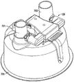
Fig. 7 shows a perspective view of an example humidification chamber.
Fig. 8A shows a perspective view of an example humidification chamber including a first microstructure configuration.
Fig. 8B and 8C show front plan views of first and second enlarged portions of the microstructure of fig. 8A.
Fig. 8D shows a cross-sectional view of an example microstructure.
Fig. 9A shows a perspective view of an example humidification chamber including a second microstructure configuration.
Fig. 9B and 9C show front plan views of first and second enlarged portions of the microstructure of fig. 9A.
Fig. 9D shows a cross-sectional view of an example microstructure.
Fig. 10A shows a front perspective view of an example patient interface.
Fig. 10B shows a front plan view of an example patient interface incorporating conductive filaments.
Fig. 11A shows a back plan view of an example patient interface including microstructures.
Fig. 11B shows a perspective view of an enlarged portion of the microstructure of fig. 11A.
Fig. 11C shows a cross-sectional view of an example microstructure.
Fig. 11D shows a back plan view of an example patient interface including microstructures.
Fig. 12A shows a schematic of the formation of water droplets on the interface surface without the incorporated microstructures.
Fig. 12B shows a schematic of water spreading on the interface surface of the bonded microstructure.
Figure 13 schematically illustrates the effect of added heat on evaporation from the microstructure.
Fig. 14 is a schematic diagram of a method of manufacturing a medical tube including a feed hopper, a screw feeder toward a die, and terminating in a corrugator.
Fig. 15 is a schematic view of a method of manufacturing a medical tubing by helical forming.
FIG. 16 is a graph of example conditions for wicking in a continuous microchannel.
Fig. 17 shows an image of a continuous microstructure.
Fig. 18A to 18L show images of continuous and discrete microstructures.
Figure 19 shows a perspective view of a humidification chamber with an inlet tube incorporating a microstructure.
Fig. 20 illustrates an embodiment in which a roughened surface may be used to enhance evaporation.
Fig. 21 illustrates another embodiment in which a roughened surface may be used to enhance evaporation.
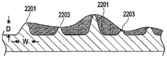
Fig. 22 shows some microstructure irregularities on the surface.
Fig. 23 illustrates an embodiment of a humidification chamber including an evaporation stack (stack) or evaporation tower.
Throughout the drawings, reference numbers are frequently reused to indicate correspondence between referenced (or similar) elements. Further, the first digit of each reference number indicates the figure in which the element first appears.
DETAILED DESCRIPTION OF EMBODIMENT (S) OF INVENTION
The following detailed description discloses new medical circuit components and methods of forming such components, such as insufflation, anesthesia, or breathing circuit components. As explained above, these components include microstructures for humidification and/or condensate management. The disclosed microstructures can be incorporated into a wide variety of components, including tubes (e.g., inspiratory and expiratory breathing tubes and other tubing between different elements of a breathing circuit, such as ventilators, humidifiers, filters, water traps, sample lines, connectors, gas analyzers, and the like), Y-connectors, conduit adapters, humidifiers, and patient interfaces (e.g., masks for covering the nose and face, nasal masks, cannulas, nasal pillows, and the like), floats (floats), probes, and sensors in a wide variety of medical circuits. Medical circuit is a broad term and is given its ordinary and customary meaning to one of ordinary skill in the art (i.e., it is not limited to a special or customized meaning). Thus, the medical circuit is meant to include an open circuit, such as certain CPAP systems, which may include a single inspiratory breathing tube between a ventilator/blower and a patient interface; a closed loop is also included.
Details regarding several illustrative embodiments for implementing the apparatus and methods described herein are described below with reference to the drawings. The invention is not limited to these described embodiments.
Medical circuit
For a more detailed understanding of the present disclosure, reference is first made to fig. 1, which shows a medical circuit according to at least one embodiment. More specifically, fig. 1 shows an example breathing circuit. Such a breathing circuit may be, for example, a continuous, variable or bi-level Positive Airway Pressure (PAP) system or another form of respiratory therapy. As explained below, the breathing circuit includes one or more medical tubes, a humidifier, and a patient interface. Any or all of these, as well as other components of the medical circuit, may incorporate microstructures for humidification and/or condensate management. Microstructures can generally be defined as structures having a microscale size in the range of 1 to 1000 micrometers (μm) (or about 1 to 1000 μm).
The gas may be conveyed in the circuit of fig. 1 as follows. The dry gas is delivered from ventilator/blower 105 to humidifier 107, which humidifies the dry gas. In some embodiments, the ventilator/blower 105 may be integrated with the humidifier 107. The humidifier 107 is connected to an inlet 109 (an end for receiving humidified gas) of the inhalation duct 103 via a port 111, thereby supplying humidified gas to the inhalation duct 103. An inspiratory tube is a tube configured to deliver breathing gas to a patient. The gas flows through the inspiratory tube 103 to the outlet 113 (the end for discharging humidified gas) and then to the patient 101 through the patient interface 115 connected to the outlet 113. In this example, the outlet 113 is a Y-piece adapter. Exhalation tube 117 is also connected to patient interface 115. An exhalation tube is a tube configured to move exhaled humidified gas away from the patient. Here, exhalation tube 117 returns exhaled humidified gas from patient interface 115 to ventilator/blower 105. Inhalation tube 103 and/or exhalation tube 117 according to at least one configuration may include microstructures. These tubes (and others) are described in more detail below.
In this example, dry gas enters ventilator/blower 105 through vent 119. The fan 121 may improve the flow of air into the ventilator/blower by drawing air or other gas through the vents 119. For example, the fan 121 may be a variable speed fan, with the electronic controller 123 controlling the fan speed. Specifically, the functions of the electronic controller 123 may be controlled by the electronic main controller 125 in response to inputs from the main controller 125 and predetermined required values (preset values) of pressure or fan speed set by the user via the dial 127.
The humidifier 107 may also include a plurality of electronic controls. In this example, the humidifier 107 includes an electronic analog or digital master controller 125. Preferably, the main controller 125 is a microprocessor-based controller that executes computer software commands stored in an associated memory. In response to user-set humidity or temperature values and other inputs entered via, for example, user interface 133, main controller 125 determines when (or at what level) to energize heater plate 131 in order to heat water 130 within humidification chamber 129.
Any suitable patient interface 115 may be incorporated. The patient interface is a broad term and is given its ordinary and customary meaning to those skilled in the art (that is, it is not limited to a special or customized meaning) and includes, without limitation, masks (e.g., endotracheal, facial, and nasal masks), cannulae, and nasal pillows. Temperature probe 135 may be connected to inspiratory tube 103 proximate to patient interface 115 or to patient interface 115. The temperature probe 135 monitors the temperature near or at the patient interface 115. A heating filament (not shown) associated with the temperature probe may be used to adjust the temperature of patient interface 115 and/or inspiratory tube 103 in order to raise the temperature of inspiratory tube 103 and/or patient interface 115 above the saturation temperature, thereby reducing the chance of unwanted condensation.
The patient interface 115 according to at least one embodiment may include microstructures and is described in more detail below.
In fig. 1, exhaled humidified gas is returned from patient interface 115 to ventilator/blower 105 via exhalation tube 117. Exhalation tube 117 may have a temperature probe and/or heating filament integrated with it (as described above with respect to inhalation tube 103), thereby reducing the chance of condensation. Furthermore, exhalation tube 117 does not need to return exhaled gas to ventilator/blower 105. Alternatively, the exhaled humidified gas may be passed directly to the ambient environment or to other auxiliary equipment, such as an air scrubber/filter (not shown). In some embodiments, the exhalation tube is omitted entirely.
As discussed above, the inspiratory tube 103, the expiratory tube 117, the humidification chamber 129, and/or the patient interface 115 of the example medical circuit may include microstructures. These components are discussed below. The invention is not limited by these embodiments, however, it is envisioned that the disclosed microstructures may be integrated into a wide variety of medical components that contact and/or transport humidified gases, such as humidified air.
Medical tube with microstructure
Fig. 2 shows a perspective view of a tube 201 suitable for use in a medical circuit, in accordance with at least one embodiment. As shown in fig. 2, the tube 201 may be corrugated, which advantageously improves the flexibility of the tube. However, in certain embodiments, the tube 201 may have relatively smooth non-corrugated walls.
In certain embodiments, tube 201 may be used to deliver gas to and/or from an infant or neonatal patient. In certain embodiments, tube 201 may be used to deliver gas to and/or from standard patients (e.g., older children and adults). Some example dimensions of "infant" and "standard" medical tubing, as well as some preferred ranges for these dimensions, described herein are described in commonly-owned U.S. provisional patent application nos. 61/492,970 filed on 3.6.2011 and 61/610,109 filed on 13.3.2012, and in commonly-owned international publication No. WO 2011/077250 a1, each of which is incorporated by reference in its entirety. An example length for an infant and standard tube may be 1 to 2m (or about 1 to 2 m).
In at least one embodiment, the tube 201 is formed from an extrudate comprising one or more polymers. Preferably, the polymer is selected such that the formed tube 201 is substantially flexible. Preferred polymers include Linear Low Density Polyethylene (LLDPE), Low Density Polyethylene (LDPE), polypropylene (PP), polyolefin plastomer (POP), Ethylene Vinyl Acetate (EVA), plasticized polyvinyl chloride (PVC), or blends of two or more of these materials. The polymer forms a weight percentage (wt%) of at least 98.4 (or about 98.4), 98.5 (or about 98.5), 98.6 (or about 98.6), 98.7 (or about 98.7), 98.8 (or about 98.8), 98.9 (or about 98.9), 99.0 (or about 99.0), 99.1 (or about 99.1), 99.2 (or about 99.2), 99.3 (or about 99.), 99.4 (or about 99.4), 99.5 (or about 99.5), 99.6 (or about 99.6), 99.7 (or about 99.7), 99.8 (or about 99.8), or 99.9 (or about 99.9) of the total extrudate. In particular embodiments, the extrudate comprises 99.488 (or about 99.488) wt% or about 99.49 (or about 99.49) wt% LLDPE. In certain embodiments, tube 201 is formed from a foamed polymer described in commonly assigned international publication number WO 2001/077250 a1, which is incorporated by reference in its entirety.
In some embodiments, the microstructures may be formed from a soft metal material such as aluminum foil, brass, and copper. In some such embodiments, the materials selected may have high surface energies. In some embodiments, the substrate materials may be coated and may include additives that increase the surface energy of the substrate material. In some embodiments, the use of a separate metal that is not formed in the microstructure may be advantageous due to the high surface energy alone. The microstructures may be formed from the metal, for example, by first forming the soft metal into a film or membrane and then stamping the material into the microstructures. The stamped material may then be used to form any number of suitable components in the humidifying device of the present disclosure. For example, at least the inner portion of the tube 201 may be formed from a metal that may or may not have been stamped to form the microstructure. And in some embodiments, the stamped metal film may form a surface on any number of structures (walls, towers, fins, bases, etc.) within the humidification chamber.
In certain embodiments, the tube 201 may include one or more conductive filaments. In certain embodiments, the tube 201 may include two or four conductive filaments, and pairs of these conductive filaments may form a connecting loop at one or both ends of the tube 201. The one or more filaments may be disposed on the exterior of the tube 201, e.g., helically wound around the exterior of the tube 201, or on the interior wall of the tube 201, e.g., helically wound around the lumen wall. Filaments are discussed in more detail below.
It has been found that interaction between a liquid and a surface comprising microstructures constructed for a particular purpose can result in the liquid spreading onto the surface and into or onto the microstructures. It has further been found that this interaction increases the liquid-vapor interface area and reduces the thickness of the liquid layer on top of the surface. The combination of increased surface area and reduced thickness improves evaporation of the liquid compared to the same volume of liquid on a flat surface. As discussed below, the combination of increased surface area, reduced thickness, and heating further improves evaporation of the liquid. Thus, in various embodiments, the inner wall of tube 201 includes microstructures 301, as shown in fig. 3A (not to scale). A first magnified view of a portion of microstructure 301 is shown in fig. 3B. Fig. 3B shows these microstructures 301 at a larger magnification than fig. 3A. In fig. 3A and 3B, the microstructures 301 are arranged axially along the tube 201 (that is, the microstructures extend in a direction perpendicular to the longitudinal length of the tube 201).
Polymers generally have low surface energy, resulting in poor wettability. To improve the water spreading capability of these microstructures 301 on polymer tube 201, it may be advantageous to treat one or more polymers with one or more materials in order to increase the surface energy. Surfactants, such as cationic surfactants, can be particularly desirable additive materials. Suitable surface modifying agents include Glycerol Monostearate (GMS), ethoxylated amines, sodium alkyl sulfonate salts, and lauric diethanolamide, as well as additives containing these materials. MLDNA-418 supplied by Clariant (New Zealand) Co., Ltd and having a product name of "418 LD antistatic masterbatch" is a surface modifier masterbatch in which 5 (+ -0.25)% of glyceryl monostearate (CAS number 123-94-4) is used as an active ingredient. Preferably, the surface modifier comprises at least about 0.05 (or about 0.05), 0.1 (or about 0.1), 0.15 (or about 0.15), 0.2 (or about 0.2), 0.25 (or about 0.25), 0.3 (or about 0.3), 0.35 (or about 0.35), 0.4 (or about 0.4), 0.45 (or about 0.45), 0.5 (or about 0.5), 1.1 (or about 1.1), 1.2 (or about 1.2), 1.3 (or about 1.3), 1.4 (or about 1.4), or 1.5 (or about 1.5) weight percent of the total extrudate. For example, in at least one embodiment, the tube extrudate comprises 0.25 wt% (or about 0.25 wt%) of the surface modifying agent. As another example, in at least one embodiment, the tube extrudate includes 0.5 wt% (or about 0.5 wt%) of the surface modifying agent.
Other materials, such as other surfactants or other hydrophilic agents, may also be used to improve the water spreading capability of the tube 201 or other embodiments. For example, any suitable anionic, cationic or nonionic surfactant or other hydrophilic agent, or combination of such surfactants or hydrophilic agents, may be used. Suitable hydrophilizing agents can be any agent or agents that generally increase the hydrophilic character of the composition. In some configurations, the surfactant or hydrophilic agent may comprise an ethoxylated fatty alcohol, such as those described in EP 0480238B 1, the entire contents of which are incorporated herein by reference. In some configurations, the surfactant or hydrophilic agent may include nonionic surfactants such as nonylphenol ethoxylates, polyethylene glycol mono-and diesters, sorbitan esters, polyethylene glycol mono-and diethers, and others described in EP 0268347B 1, or nonionic perfluoroalkylated (perfluorinated) surfactants such as those described in WO 87/03001, all of which are described inThe contents of which are incorporated herein by reference. In some configurations, the surfactant or hydrophilic agent may contain a silicon moiety. In some configurations, the surfactant or hydrophilic agent may include a wetting agent, such as a hydrophilic silicone oil as described in WO 87/03001 and EP 0231420B 1, as mentioned above, the entire contents of which are incorporated herein by reference. In some configurations, the surfactant or hydrophilic agent may include a polyether carbosilane, such as those described in WO 2007/001869, particularly at pages 13 and 14, which are incorporated herein by reference in their entirety. Other such suitable materials are described in US 5,750,589, US 4,657,959 and EP 0231420B 1, as cited in WO 2007/001869, the entire contents of which are incorporated herein by reference. In some configurations, the surfactant or hydrophilic agent may include an ethoxylated surfactant containing a siloxane solubilizing group, such as those described in US 4,657,949 and WO 2007/001869 mentioned above. Examples of such ethoxylated surfactants are the surface active copolymers available from Momentive Performance Materials Albani (Albany) of Momentive Performance Materials, N.Y. The first and second electrodes are electrically connected to each other (e.g.,
 l-77) and available from Emerson Performance Materials, Inc. (Emerald Performance Materials) Kyogawells (Cuyahoga Falls), Inc., Ohio, USA
 SF19。
SF19。
Other methods may also be used to increase the surface energy. Suitable methods include physical, chemical, and radiation methods. Physical methods include, for example, physical adsorption and langmuir-blodgett membranes. Chemical methods include oxidation by strong acids, ozone treatment, chemisorption, and flame treatment. Irradiation methods include plasma (glow discharge), corona discharge, photo-activation (UV), laser, ion beam, electron beam, and gamma irradiation.
By selecting a suitable surface modification method or surface modifier, it is possible to provide a pipe wall having a surface property contact angle of less than 50 (or about 50), 45 (or about 45), 40 (or about 40), 35 (or about 35), 30 (or about 30), 25 (or about 25), 20 (or about 20) degrees (°), as can be measured by an angle measuring device (e.g., goniometer). For example, a tube wall having a surface characteristic contact angle of less than 35 ° (or about 35 °) provides useful results. Desirably, the contact angle is less than π/2 (or about π/2). More desirably, the contact angle is 0 ° or about 0 °.
Table 1 below shows the contact angle measurements for different LLDPE samples, including samples treated with a surface modifier and samples treated with radiation. The contact angle measurement is based on a static droplet shape test method performed according to ASTM standard D7334, 2008, "standard practice for surface wettability of coatings, substrates and pigments by advancing contact angle measurement".
TABLE 1

The sample with 5% MLDNA-418 surface modifier produced the lowest measured contact angle compared to the other surface modification methods tested.
As discussed above, in certain embodiments, an additive material is added to the bulk polymer extrudate. It may be desirable to add this material to the polymer matrix in order to complement the surface with the additive material for the service life of the pipe. In some configurations, the material may be added to the polymer as a surface treatment, for example, by coating the surface of the polymer with the material. For example, the microstructured surface may be brushed, sprayed, or otherwise coated with an additive material, such as a HYDRON anti-fog coating (MXL industries, Lancaster, Pa.), an EXXENE anti-foam (anti-form) coating, such as HCAF-100 (Corpus Christi Exxene, Tex.), and a Moclone (MAKROLON) anti-fog coating (Bayer corporation), to produce a thin (e.g., 1 μm or so) coating of the additive material. Surface coatings may be desirable for reasons of low cost and ease of manufacture.
In some configurations, a film of a hydrophilic material, such as a breathable polyurethane, for example, ESTANE 58245 (wackliffe Lubrizol, ohio), a breathable polyester, for example, ARNITEL VT3108 (DSM Engineering Plastics, Sittard, netherlands), or a breathable polyamide, for example, PEBAX (colorbes, akoma), may be cast as a surface modifier. These hydrophilic materials can absorb moisture and become very wettable. An example method of implementing a hydrophilic membrane includes: the breathable polymer is dissolved in a solvent, the mixture is cast, and the solvent is allowed to evaporate, thus leaving a film of the breathable material on the microstructure. For example, ESTANE 58245 pellets can be dissolved in Tetrahydrofuran (THF) in Dimethylformamide (DMF) solvent and cast onto microstructures that are machined from brass or aluminum using a micro-milling process. Typical dimensions of the film are in the range of 1 to 10 μm (or about 1 to 10 μm). Preferably, the combination of the solvent, the breathable material, and the microstructure material is selected such that, for example, by dissolving the microstructure with the solvent, the shape and quality of the microstructure is substantially unaffected.
Certain embodiments include the implementation of the vertical configuration shown in fig. 3A and 3B, which may advantageously improve humidification and condensate management. As shown in fig. 1, the tubes (e.g., 103 and 117) extend generally in a horizontal direction, although some portions may extend vertically, particularly near the ends of the tubes, and some portions may be angled. Under the influence of gravity, the condensate tends to flow down the vertical and inclined portions of the tube and pool at the lowest point of the generally horizontal tube. When the microstructures are perpendicular to the bottom of the generally horizontal tube, the microstructures will cause the pooled condensate to move vertically against gravity. This action increases the amount of condensate on the tube walls and thereby increases the surface area of condensate exposed to the air flow. The greater surface area of the condensate exposed to the air stream increases the likelihood that the condensate will evaporate into the air stream. Thus, the vertical configuration reduces the condensate that collects in the tubes and increases the likelihood that the air passing through the tubes will maintain a desired near-saturated humidity level.
This arrangement may be advantageous because it causes minimal disruption of the airflow in the tube lumen, since there are no structures extending into the lumen. At least one embodiment includes the realization of microstructures that do not necessarily extend into or cover the lumen in order to enhance evaporation.
According to some embodiments, the microstructures may be oriented in the direction of the tube. For example, fig. 19 shows an embodiment of a chamber 129 with a tube 1901 attached at the inlet 701 that incorporates a microstructure 1903. The tube 1901 may be located at the inlet 701 of the evaporation chamber 129. A liquid, such as water, may be dispensed into tube 1901 a distance above inlet 701 such that the water flows through microstructures 1903 and follows in the direction of humidification chamber 129.
In some configurations, an amount of liquid may be taken onto the inner surface of tube 1901 such that the controlled introduction surrounds the circumference and spreads the liquid along the inner surface of tube 1901 by using microstructure and gravity. Any suitable rate limiting device may be used to control the introduction of the liquid. The rate of water flow into the tube 1901 can be adjusted using a rate limiting device to maximize the interaction between the water of the microstructures 1903 in the tube 1901. For example, increasing the amount of water in tube 1901 may increase the amount of evaporation that occurs. However, these microstructures 1903 may be most effective if not completely covered or coated in water. It has been found that evaporation occurs on a rough surface, mainly along the edges of the water and surrounding structures. Accordingly, it may be desirable to control the amount of water flowing through the tube 1901 so as to maximize the number of edges for the water.
In some configurations, the liquid supply tube may extend between the rate limiting device and the collar. The collar may include microchannels on the outer surface of the sleeve, which may be in communication with microchannels on the tube 1901. As such, the collar may be used to supply liquid to the tube 1901. Furthermore, the collar may comprise an outer surface to which the gas supply conduit may be connected. Air flowing down or through tube 1901 toward humidification chamber 129 begins to evaporate and entrain water from the inner surface of tube 1901. Thus, the air reaching the humidification chamber 129 has already gained at least some water vapor.
In some embodiments (not shown), a thermal jacket may also be incorporated in, or may surround, at least a portion of the tube 1901. The thermal jacket may further enhance the evaporation of water or liquid into the flowing gas. In some embodiments, rather than or in addition to having a thermal jacket, the tube 1901 can have a heater printed (printed) on one or more portions of the tube 1901. In some embodiments, tube 1901 may include a structure such as a thick film heating element, a corrosive foil, or a wire element to provide a heating element.
The tubes 1901 having these microstructures 1903 can be formed in any suitable manner and using any suitable material. In some embodiments, the tube 1901 may be formed from corrugated sheets formed from a hydrophilic polymer. Once formed, the corrugated material may be rolled to form a tube 1901 having the microstructures 1903 that extend along at least a portion of the length of the inner surface of the resulting structure. In some embodiments, the microstructures 1903 are V-grooves. In some embodiments, the V-grooves comprise grooves that are approximately 30 μm from adjacent grooves when the plate is laid flat. In some configurations, the plate, and thus the resulting tube 1901, may be about 150mm long, and may have a diameter of about 20mm after being folded to form the tube 1901.
Fig. 4 illustrates a cross-sectional view of an example microstructure 301. In this example embodiment, the microstructure 301 is a continuous microchannel having a wedge-like structure. A continuous microchannel may generally be defined as a continuous channel having a dimension of 1000 μm (or about 1000 μm) or less. In at least one embodiment, the microchannels have a depth d of 20-40 μm (or about 20-40 μm), a maximum width w of 20 μm (or about 20 μm), and an angle θ of 30-60 ° (or about 30-60 °). In certain embodiments, the tube surface has a microchannel-to-solids ratio of 1:1 (or about 1: 1). The foregoing dimensions are not limiting, and further suitable dimensions are discussed in further detail below. Due to the dimensional differences discussed above between these example embodiments and these example tube dimensions, the microstructured surface can reside and operate in an open system rather than a closed system (e.g., lab-on-a-chip).
Certain embodiments include achieving movement of the liquid in the microchannel based primarily on surface forces rather than inertial or gravitational forces. Certain embodiments further comprise the realization that if the feature size of the microstructure is less than the capillary length (L)c) Then the surface force is usually dominant and the capillary length is defined as

Where γ represents the surface tension, ρ represents the fluid density, and g represents the gravitational acceleration constant (9.8 m/s)2). For water at room temperature, the capillary length is about 2.3 mm. In accordance with the foregoing implementation, microscale sizes of less than about 2.3mm may result in observable surface phenomena for water at room temperature. However, it was found that the size of these microstructures does not always indicate whether there is observable capillary wicking, an increase in surface area, and/or a decrease in film thickness. Thus, in certain embodiments, the microstructures comprise a base substrate having an equilibrium contact angle of less than π/2 (or about π/2). Under isothermal (or near isothermal) conditions, and on a length scale less than the capillary length, a criterion for wicking can be defined that depends on the aspect ratio of the microstructure and the critical equilibrium contact angle. For a square slot, the relationship can be expressed as

Wherein X is the aspect ratio. For a v-groove, the relationship can be expressed as

Wherein β is the angle of the groove wedge. FIG. 16 is a graph of example conditions for wicking in a continuous microchannel, particularly square grooves (1601) and v-grooves (1603). In the region below the curve, wicking into the channel tends to occur. In the region slightly above the curve, many droplets in metastable equilibrium were observed, but wicking was not prone to occur. In the region of the upper curve, no continuous droplet was observed and no wicking occurred. Different combinations of surface wettability and channel aspect ratio will result in the wicking of liquids into these microchannels provided the characteristic dimension is less than the capillary length for the liquid (so that the surface tension is stronger than the viscous forces). However, in general, if the conditions are such that θCritical point ofBelow the curve, liquid will wick into the channel.
It was determined from the above implementation that structures with high aspect ratios and/or high surface energies (low contact angles) are desirable in order to promote wicking. Surfactants, such as those discussed above, can result in contact angles near 0 ° and therefore wicking can occur with ease. The equilibrium contact angle on most polymer surfaces is greater than about 0.87 radians (about 50 °), so deeper channels can be implemented to promote wetting.
Surface roughness or microstructure (e.g., regular microstructure) can facilitate dispersion of the liquid droplets and thus can reduce the thickness/depth of the liquid droplets, which increases the liquid/vapor surface area when the equilibrium contact angle is less than about 90 °. The surface roughness of the microchannels can also play a role in wicking. It is believed that the microstructured or nanostructured protrusions (bump) within these microchannels may pin the solid/liquid/vapor contact line, increase surface area, and/or act as nucleation sites for condensation. Fig. 17 shows microchannels similar to those shown in fig. 18C, but observed using an ambient scanning electron microscope. The roughness can be clearly seen on the surface. In some configurations, if the contact angle is greater than about 90 °, the surface roughness has a deleterious effect on spreading and evaporation, as the droplets will spread less, which will reduce the liquid/vapor surface area. For at least this reason, configurations having an equilibrium contact angle of less than about 90 ° are generally preferred.
Many different shapes of microstructures can achieve the desired result. For example, the continuous microchannel cross-section may be sinusoidal or sharp. In certain embodiments, the microchannels have aspect ratios that increase with distance (e.g., chemical or physical gradients). In some embodiments, a channel depth gradient is used to control the movement of liquid in a particular direction. It has been found that the liquid tends to move in the direction of the deeper channels. The gradient may be desirable because, given a slow hysteresis, the substrate may force the droplet to move towards a region of higher energy in order to lower it. The gradient may also accelerate or otherwise improve wicking of the liquid. For example, in some embodiments, a channel depth gradient is used to move liquid toward areas with higher air flow, thereby increasing evaporation. In some embodiments, larger channels along the vertical arms of the structure are used in order to direct water from the bottom of the structure to the top of the corrugated structure, thereby bringing the water closer to the heating elements for evaporation.
Furthermore, the microstructure need not be continuous. The discrete microstructures aid in liquid dispersion, thereby accelerating evaporation. It has been found that on rough surfaces most of the evaporation occurs around the transition zone of the solid structure and the liquid (i.e. at the edges of the liquid). Thus, increasing the roughness of the overall structure increases the transition region and improves evaporation. For example, the surface may contain discrete features such as cylindrical, conical, or cubic posts or posts. The microstructures may also comprise a hierarchical structure of the foregoing features. In some embodiments, the discrete features are uniform or partially uniform. In some embodiments, the discrete features are randomly distributed on the surface. For example, some embodiments utilize crystals having irregular shapes that are distributed throughout or attached to a surface. In some embodiments, an irregular surface (i.e., not smooth) may advantageously improve evaporation.
Fig. 20 and 21 illustrate embodiments that utilize irregular or rough surfaces to enhance liquid evaporation. Fig. 20 shows that liquid can be applied to the roughened surface 2001 using a dispensing mechanism 2003 located at a distance D from the surface 2001 that outputs a small amount of liquid. In some configurations, the droplets are emitted one drop at a time. In some configurations, the droplets may sputter upon contact, which results in smaller droplets.
Each droplet may contact a rough or irregular surface 2001 and spread rapidly over the surface 2001, thereby enhancing evaporation of the liquid into the gas flowing over the surface 2001. In some embodiments, surface 2001 is heated to further enhance evaporation of the liquid into the passing gas. While the embodiment in FIG. 20 has been shown with only a single liquid dispenser 2003, or drop tube, some embodiments, as shown in FIG. 21, may include more than one liquid dispenser 2003. Multiple liquid dispensers 2101 may be located at different locations on the surface 2001 to increase the coverage of liquid on the surface 2001. In some embodiments (not shown), a surface comprising a plurality of holes is used as the liquid distributor 2101. Allowing liquid (such as water) to flow over the surface. The liquid then drips or falls through a plurality of holes in the surface onto the underlying rough or irregular surface 2001. The gas may flow between the two surfaces (i.e., the first surface and the rough or irregular surface 2001) and cause the liquid to evaporate as it falls, before dispersing in the microstructure of the rough or irregular surface 2101. Fig. 21 further illustrates that in some embodiments, the flow of gas (e.g., air) to be humidified may be directed or shaped to form a relatively flat flow over the roughened surface 2001. Such a configuration may force more gas to interact with the roughened surface 2001.
Fig. 22 illustrates one type of rough surface comprising a plurality of ridges 2201 having different heights and widths. It is believed that a rough surface with a higher aspect ratio (i.e., a steeper slope) spreads the liquid and increases evaporation. In some configurations, having a steeper slope is believed to increase the number of contact lines. In some embodiments, increasing the number of lines of contact between the liquid and the roughened surface is believed to increase evaporation. In some embodiments, the presence of taller ridges 2201 may increase the number of lines of contact between the liquid and the roughened surface, thereby increasing evaporation relative to a surface with shorter ridges 2203. In some embodiments, the rate of evaporation, particularly at the contact line, may be increased by the heat applied to the roughened surface. In some embodiments, using a surface having an integral microstructure (i.e., a microstructure integrally connected to the underlying surface) may allow for better heat transfer (if the underlying surface is heated). Such an arrangement may improve the ability of the heat to assist in the evaporation of the liquid.
Although the discussion above with respect to fig. 20-22 refers to a rough or irregular surface, a microstructured surface having a regular pattern may achieve similar results. Similar to droplets on a rough surface, droplets on a surface with microstructures will disperse and evaporate into the passing gas faster than a smooth surface without microstructures or surface irregularities. In some embodiments, the microstructures are uniform. In some embodiments, the microstructures are sized and arranged according to a pattern if not every microstructure is the same.
If the wicking criteria discussed above are met, the water will wick into the microchannel and/or microcolumn due to some kinetics, known as Lucas-Walsh kinetics. The square root of the wicking length (L) with respect to time (t) And proportionally increased regardless of the shape or aspect ratio of the channel, so long as it has a uniform cross-section. A is a function of surface tension, viscosity, cross-sectional area of the channel, and contact angle. Therefore, what determines the strength of this relationship (i.e., the value of a) depends on some or all of these parameters.
Certain embodiments include achieving low contact angles, high aspect ratios, high surface tension, and low viscosity may result in improved wicking. Since the wicking length is proportional to the square root of time, the wicking rate is inversely proportional to the length and inversely proportional to the square root of time. Stated another way, wicking slows down with distance and over time.
Fig. 18A to 18L show images of continuous and discrete microstructures. The base material in fig. 18A is polyethylene terephthalate (PET). The base material in the other figures is acrylic. The v-shaped grooves in fig. 18A were cut using a double-edged razor blade. Other microstructures were made using a 3D printer (ProJet HD 3000). In some embodiments, the microstructure or the surface incorporating the microstructure may be fabricated by direct injection molding or hot embossing. Although not shown in these figures, it is also possible to machine the microstructures using CNC machines equipped with Micro-end mills, such as those sold by Performance Micro tools (Performance Micro Tool) (ussville, wisconsin). Fig. 18B and 18C show a square groove. Fig. 18D shows a front view of a square micro-tunnel array with a gradient in topography, and in particular a front view of the long ends of the micro-tunnels. FIG. 18E shows a front view of the short end of the microchannel of FIG. 18D. FIG. 18F shows a side view of the square micro-tunnel array of FIG. 18D. As discussed herein, wicking kinetics (specifically, the velocity-time relationship) can potentially be altered by microstructures having a change in depth of separation distance due to a gradient in the topography. Such topography can desirably affect the manner in which a liquid evaporates and condenses on a surface. Such variable depth configurations may be achieved by embossing, machining, or casting. Fig. 18G shows a droplet on a square groove that has not been treated with a surfactant. Fig. 18H shows spreading of the droplet on the surfactant treated square groove. Fig. 18I and 18J show top-down views of a surface with pillars at different magnifications. Figure 18K shows a side view of a surface with pillars. Fig. 18L shows another embodiment of a microstructure defining a surface shape that is an inverse of the shape of the microstructure of fig. 18A. The microstructure of fig. 18L comprises alternating taller and shorter ridges, each separated from each other by a small channel or first microchannel. Preferably, these taller ridges are substantially taller than these shorter ridges, and may be 2-3 times taller than these shorter ridges, or 2-3 times taller than these shorter ridges. In the illustrated arrangement, the shorter ridges are substantially wider than the taller ridges, such as, for example, about 3-5 times wider than them. The small channels may be of any suitable size, such as, for example, about the width of the higher ridges. In addition, these higher ridges define large channels or second microchannels therebetween, which may be in communication with or continuous with these small channels. The depth of the large channels may be greater than the depth of the small channels, for example up to 2-3 times greater, or 2-3 times greater than the small channels. The small channels may be generally triangular in cross-sectional shape, while the large channels may have a cross-sectional shape generally resembling an inverted trapezoid. Since it is preferred that the shorter ridges define areas that are significantly larger than the areas defined by the taller ridges, the upper surface of the shorter ridges can be considered the outer surface of the material or substrate from which the small channels are recessed and from which the taller ridges protrude.
These microstructures 301 may extend along the entire length of the tube 201 or along a portion of the length of the tube 201 (e.g., a central portion where condensate may collect). Alternatively, the microstructures 301 may extend along the tube 201 at regular or irregular intervals, the intervals being separated by portions that do not have microstructures. The aforementioned figures show the microstructures 301 around the inner circumference of the tube 201. However, the microstructures 301 need not surround the entire inner circumference in all embodiments. For example, the microstructures 301 may be arranged around half or a quarter of the circumference.
It has been found that if heat is supplied to the substrate below the liquid, a single droplet can spread many times its diameter and very efficient evaporation of the liquid can be achieved. Thus, in certain embodiments, one or more of the filaments discussed above comprise a heating filament. The heating filament may be embedded or encapsulated in the wall of the tube 201. For example, the one or more filaments may be helically coiled around the tube lumen in the wall of the tube 201. The one or more filaments may be disposed within the tube 201 in a helically coiled configuration, for example, as described in U.S. patent No. 6,078,730 to Huddard et al, which is incorporated by reference herein in its entirety. The arrangement of the heating filament is not limited to the one of the aforementioned configurations. Further, the heating filament may be arranged in a combination of the aforementioned configurations.
In certain embodiments, the tube 201 includes an inner member comprising a microstructure. An example internal component 501 is shown in fig. 5A-5B. An enlarged view of the internal components 501 is shown in fig. 5B. The example inner member 501 is a saw tooth strip. The serrations of the inner member 510 may be sized and configured to complement the corrugations of the tube (not shown) such that the tube substantially holds the inner member 501 in place. In fig. 5B, the microstructures 301 extend vertically to cover both axial surfaces of the inner member 501 along the longitudinal length of the inner member 501. Alternatively, the microstructure 301 may cover one axial surface. In some configurations, microstructures 301 can extend along a portion of the longitudinal length or at regular or irregular intervals along the longitudinal length. The inner member 501 may include more than one sawtooth rack. For example, the inner member may include two saw tooth bars and resemble a plus sign with saw teeth along the longitudinal length. These examples are not intended to be limiting. A greater number of strips may be incorporated. However, it may be advantageous to have a lower number of strips in order to improve the air flow through the tube lumen and/or to improve the flexibility of the tube.
The inclusion of the inner member 501 may be advantageous because the inner member 501 may allow the microstructures 301 to extend into the tube lumen and reach the center of the tube 201 lumen. As shown in fig. 6, the air flow rate increases gradually from the tube wall to the center of the tube lumen (centerline) and reaches a maximum at the centerline. Thus, the water rising onto the microstructures 301 in fig. 5A and 5B is exposed to a stream of warmed, higher velocity air. The higher air velocity at which the condensate is exposed near the center of the tube increases the likelihood that the condensate will evaporate into the air stream.
Alternative configurations for the internal components 501 are possible. For example, the inner member 501 may be coiled inside the tube 201. This configuration may be desirable because it allows the microstructures to extend a distance into the lumen of tube 201 that is exposed to a higher airflow rate than the walls of tube 201. In at least one embodiment, the inner member 501 is coiled such that at least a portion of the inner member 501 passes over the center of the tube lumen.
As mentioned above, it has been found that heat added to the microstructured surface can significantly increase the evaporation rate. Thus, the inner member 501 of any of the foregoing embodiments may incorporate heating filaments that can improve the heating of the air flow along the tube, and thus increase the likelihood that condensate in the microchannels will evaporate into the air flow. Incorporating one or more heating filaments into the inner member 501 also reduces the likelihood that condensation will occur on the warmed inner member. It has been found that evaporation is strongest at the contact zone where the solid surface, liquid droplets, and evaporated vapor meet. This is due to the proximity of the heated surface. The closer to the solid, the higher the mass transfer. Thus, certain embodiments include implementations with a greater number of narrower channels that may be desirable. For example, a higher evaporation rate can be achieved on a surface with ten 100 μm channels than on a surface with five 200 μm channels.
It should be noted that the above-described configuration of the microstructure may be advantageous in that it may be used to transport liquids without the use of a pump or pumps. Furthermore, certain embodiments include the realization that a pump will not be required to direct the microstructured surface of the liquid, as liquid movement is driven by capillary action.
Method for manufacturing a tube
As mentioned above, the tube may be made of one or more extruded polymer parts. The characteristics of the extrudate (including composition, surface modifier, method for increasing surface energy) are described above.
A first manufacturing method is described with reference to fig. 14. The method includes extruding an elongated tube having a longitudinal axis, a lumen extending along the longitudinal axis, and a wall surrounding the lumen. The microstructures may be pressed or otherwise formed onto the tube during extrusion. The microstructures may also be shaped, printed, cut, thermoformed, or otherwise formed on the tube after extrusion. As shown in fig. 4, 8D, and 9D, it was observed that cutting microchannels into a surface using a sharp object can result in raised edges around the top portion of the microchannel. Thus, in some processes, it may be desirable to grind or polish the surface after the formation of the microchannels in order to improve the uniformity of the surface. The method may further comprise corrugating the elongate tube, for example using a corrugating die. More specifically, the process involves mixing or providing a masterbatch of extrudate material (i.e., material for extrusion), feeding the masterbatch into an extrusion die, extruding an extrudate as described above, and (optionally) feeding the elongated tube into a corrugator using an endless chain of mold blocks to form a corrugated tube.
Fig. 14 generally illustrates an arrangement in which a feed hopper 1401 for receiving raw ingredients or materials (e.g., masterbatch and other materials) is provided that will be conveyed through a feed screw 1403 driven by a motor 1405 in a direction a toward a die 1407. A molten tube 1409 is extruded from a die 1411. The conductive filaments may optionally be coextruded on or in a melt tube 1409.
Extruders, such as the Werex (Welex) extruder equipped with 30mm to 40mm diameter screws and typically having a 12mm to 16mm annular die with 0.5mm to 1.0mm clearance, have been found suitable for the rapid production of low cost tubes. Similar extrusion machines are available from the american library (Kuhne) (germany), AXON AB plastics machinery (sweden), AMUT (italy), and Battenfeld (germany and china). Have found applications such as Corrugator mills, such as the corrugator mills manufactured and supplied (hasford, germany), are suitable for the corrugation forming step. Similar machines are available from OLMAS (california, italy), huakusu machinery manufacturing limited (celadon, china), or tuypro industry (achievement) limited (achievements, china).
During manufacture, molten tube 1409 is transferred between a series of rotating dies/blocks on a corrugator after exiting extruder die 1411 and forms a corrugated tube. The molten tube is formed by vacuum applied to the outside of the tube via slots and channels through the blocks and/or pressure applied to the inside of the tube via air channels through the center of the extruder die core. A specially shaped long inner rod extending from the core needle and closely fitting the inside of the corrugations may be required if internal pressure is applied, in order to prevent air pressure from escaping in an end-first fashion (endways) along the tube.
The tube may also include a flat cuff region for connection to an end connector fitting. Thus, during manufacture, the molded plastic end connector fitting may be permanently secured and/or hermetically sealed by friction fit, adhesive bonding, overmolding, or by thermal or ultrasonic welding.
Another suitable method for manufacturing a tube according to embodiments described herein involves spiral forming, as shown in fig. 15. In general, the method includes extruding a tape and helically winding the extruded tape around a mandrel, thereby forming an elongated tube having a longitudinal axis, a lumen extending along the longitudinal axis, and a wall surrounding the lumen. The method may further comprise optionally corrugating the elongate tube. The microstructures may be pressed or otherwise formed onto the ribbon during the extrusion process. The microstructures may also be shaped, printed, cut, thermoformed, or otherwise formed on the ribbon after extrusion. Further, the microstructures may also be shaped, printed, cut, thermoformed, or otherwise formed on the assembled conduits. In some methods, it may be desirable to grind or polish the surface after the microchannels are formed in order to improve the uniformity of the surface.
The extrusion process involves mixing or providing a masterbatch of extrudate material (i.e., material for extrusion), feeding the masterbatch into an extrusion die, and extruding the extrudate into a ribbon.
The extruded or preformed tape is then helically wound. In some embodiments, the reinforcing beads overlie the turns of the tape. The bead may provide helical reinforcement of the tube against crushing and may also provide a source of thermal, chemical or mechanical adhesive for fusing or joining the overlapping belt portions.
Shown in fig. 15 is a melt extruded tube 1501 exiting the die 1503 of the extruder prior to passing into the corrugator 1505. Upon exiting the corrugator 1505, a heating wire 1507 is wound around the outside of the shaped tubular member.
One advantage of the preferred type of tube manufacture described above with reference to fig. 15 is that some of the die blocks B may include end ferrule features that are simultaneously formed into a tubular member. Manufacturing speed can be significantly increased by complexity reduction and elimination of secondary manufacturing processes. While this method is an improvement over the separate cuff forming process, a disadvantage of the conventional cuffs of the prior art is that the corrugator must be decelerated to allow the wall thickness of the tube to increase in this region (the extruder continues at the same speed). The ferrule thickness is increased to achieve increased ferrule strength and sealing characteristics with the ferrule adapter fitting. Furthermore, during the limited contact time with the corrugator block, the heat of the molten polymer in this thicker region is difficult to remove and this can become an important limiting factor for the maximum operating speed of the pipe line.
Humidifying chamber with microstructure
Referring next to fig. 7, a humidification chamber 129 is shown in accordance with at least one embodiment. The humidification chamber 129 generally includes an inlet 701 and an outlet 703. The chamber 129 is configured to be mounted on a heating plate (element 131 as discussed above in fig. 1) such that the base 705 of the chamber contacts the heating plate 131. The base 705 preferably comprises a metal having good thermal conductivity, such as aluminum and copper. Humidification chamber 129 is further configured to hold a volume of liquid, such as water. In use, the liquid contacts a substantial portion of the base 705. The heater plate 131 heats the base 705 of the chamber 129, thereby causing at least some of the liquid in the chamber 129 to evaporate. In use, gas flows into the chamber 129 via the inlet 701. The gas is humidified in the chamber 129 and exits the chamber 129 through the outlet 703.
Fig. 8A shows an example configuration of the microstructure 801 of the humidification chamber 129. The characteristics of microstructure 801 discussed in the preceding sections are incorporated by reference. As shown in this example, the microstructures 801 are arranged vertically around the circumference of the humidification chamber 129. In other words, the microstructures are perpendicular (or substantially perpendicular) to the base 705 of chamber 129. These microstructures in fig. 8A are shown larger than actual size for illustrative purposes only. The vertical microstructures 801 carry the water 130 up the sides of the chamber 129 so that a greater surface area of the water 130 is exposed to the air flow within the chamber 129. In at least one embodiment, the microstructures extend from the base of the chamber a distance that is 100%, 99%, 95%, from 95% to 99%, 90%, or from 90% to 95% (or about so) of the height of chamber 129. The height of chamber 129 may be 50mm (or about 50 mm). In certain configurations, one or more additives, such as SILWET surfactants (albany, high new materials group, new york, n.y.), may be included in the water 130 to enhance uptake by these microstructures.
Although in 8A the microstructures 801 are arranged around the entire circumference of the chamber 129, it should be understood that in some embodiments the microstructures 801 are arranged less than the entire circumference. For example, the microstructures 801 may be arranged in a single portion of the chamber 129 or at random or fixed intervals around the chamber 129.
Fig. 8B shows a first enlarged view of a portion of the microstructure of fig. 8A. As shown in fig. 8B, water travels onto vertical microstructures 801. The micro-scale water droplets in or on these microstructures 801 are exposed to the air flow within chamber 129. Fig. 8C shows a second enlarged view of a portion of the microstructure of fig. 8A. As shown in fig. 8C, air flows through chamber 129 and across microstructures 801 causing at least some of the water droplets in microstructures 801 to evaporate. Evaporated water from these microstructures 801 enters the air stream as a vapor.
As shown in the previous figures, these microstructures 801 expose a greater surface area of the water 130 in the chamber 129 to the passing air flow, thereby increasing the efficiency of the chamber 129 compared to a chamber without any microstructures.
Fig. 8D shows a cross-sectional view of an example microstructure 801. In this exemplary embodiment, the microstructures 801 are wedge-shaped microchannels. The properties of these microstructures described above with respect to the tube configuration may also be incorporated into the microstructures for the humidification chamber configuration.
Fig. 9A shows another example configuration of the microstructure of the humidification chamber 129. As shown, these microstructures may be arranged vertically and horizontally within humidification chamber 129. The vertically arranged microstructures are perpendicular (or substantially perpendicular) to base 605 and are designated as 901, while the horizontally arranged microstructures are parallel (or substantially parallel) to base 705 and are designated as 903. Moreover, these microstructures are shown larger than actual size, for illustrative purposes only. Generally, in the configuration of fig. 9A, vertically arranged microstructures 901 carry water 130 up the sides of chamber 129. Horizontally arranged microstructures 903 spread the micro-scale water droplets from vertically arranged microstructures 901 around the top of chamber 129, exposing a larger surface area of water to the air flow than a chamber without any microstructures. The microstructures 901 and 903 thereby increase the efficiency of the chamber.
Fig. 9B shows a first enlarged view of a portion of the microstructure of fig. 9A. As shown in fig. 9B, the water travels onto vertically arranged microstructures 901. When a micro-scale water droplet reaches the top of its corresponding vertically arranged microstructure 901, it proceeds further along its corresponding horizontally arranged microstructure 903 (or group of microstructures). Fig. 9C shows a second enlarged view of a portion of the microstructure of fig. 9A. As shown in fig. 9C, air flows through chamber 129 and across microstructures 901 and 903, causing at least some of the water droplets in microstructures 901 and 903 to evaporate. The evaporated water from these microstructures 901 and 903 enters the air stream as a vapor. In an alternative configuration (not shown), chamber 129 may be configured to cause water to flow down these microstructures under gravity (rather than against gravity). Also, the combination of channels and pins may direct the flow in any desired manner.
The vertical microstructures 901 may be similar to those shown above in fig. 8D and elsewhere in this disclosure, and the above discussion of their shapes and characteristics is incorporated herein by reference. Fig. 9D shows a cross-section of an example horizontal microstructure 903.
The shape and configuration of vertically arranged microstructures 901 and horizontally arranged microstructures 903 in fig. 9A-9D are for illustration purposes only. The invention is not limited to the disclosed embodiments.
For the reasons explained above with respect to the embodiments of the tube, it may be desirable to utilize a microstructure in combination with a surface having a desired surface energy in order to improve the wettability and water spreading characteristics of the surface. Metals and glasses are known to have relatively high surface energy and good wettability. Thus, the inner surface of chamber 129 may comprise metal or glass. Metals such as aluminum or copper may be desirable because these materials also readily conduct heat, which may increase the evaporation rate within the chamber. Glass may be desirable because its optical transparency may allow a user to visually inspect the level of liquid within the chamber. Plastics are particularly desirable materials for chamber 129 because of their low cost and ease of use in manufacturing. However, as explained above, plastics have relatively low surface energies. Thus, it may be desirable to treat the plastic with additives in order to increase the surface energy, as explained above. In at least one configuration, the chamber 129 walls comprise poly (methyl methacrylate) plastic having inner walls coated with a layer of conductive metal (e.g., gold). In another configuration, the inner surface of the chamber 129 wall comprises a ceramic material, garnet, or sintered material (e.g., TiO)2)。
As mentioned above, it has been found that heat added to the microstructured surface can significantly increase the evaporation rate. Thus, the chamber 129 may incorporate heating filaments in the wall, which may improve the heating of the wall and thus the possibility of evaporation of the liquid in or on these microstructures. In at least one configuration, a heating shield may be placed around chamber 129 to improve heat transfer to chamber 129. In addition, an insulating jacket may be placed around the chamber 129 to prevent heat loss and improve heat retention within the chamber 129.
Fig. 23 illustrates an embodiment of a humidification chamber 2301 comprising a plurality of laminations 2303 having microstructures 2305 on at least some surfaces of the laminations 2303. As illustrated, laminations 2303 may be arranged as a number of fins or walls; however, other configurations may include a combination of columns, pillars or fins, towers, and pillars. As shown, the laminations 2303 may be arranged as fins oriented in the direction of airflow through the humidification chamber 2301. However, other configurations may also be used, extending into the flow through the chamber 2301 and inducing stronger mixing and interaction with the microstructures 2305, and thus stronger evaporation. Also, in some embodiments, different laminations may have different heights, creating an irregular flow pattern or turbulence for the gas passing through humidification chamber 2301.
In the illustrated embodiment, humidification chamber 2301 may be heated. In some embodiments, one or more laminations 2303 can comprise a thermally conductive material, such as a metal, to further enhance evaporation. In some embodiments, all exposed surfaces of each lamination 2303 may incorporate microstructures 2305, which may draw water 2307 up from the bottom of chamber 2301 to portions of chamber 2301 that have increased air flow or where the air is less humid and thus cause more moisture to evaporate. Chamber 2301 is shown as a square box; however, other shapes may be used, such as rectangular, cylindrical, spherical, domed, etc.
The microstructures may be incorporated into any number of structures within the humidification system. One such structure is the base or bottom of the humidification chamber itself. In some embodiments, the use of microstructures or irregular surface features on the bottom of the humidification chamber can disperse the fluid and create a larger surface area for enhanced evaporation. In some embodiments, the use of microstructures may act to reduce the depth of the liquid, thereby enhancing evaporation. In some embodiments, the microstructures may be configured in a pattern, such as a linear pattern or a rectilinear pattern or a circular pattern. In some embodiments, a linear pattern or a straight pattern increases the surface area better than a circular pattern. In some embodiments there is no pattern and the surface comprises irregular protrusions or surface irregularities.
Patient interface with microstructures
Condensate management is an important design issue for patient interface design. Thus, certain embodiments include implementations in which microstructures may be incorporated in patient interfaces including, but not limited to, masks (e.g., tracheal, facial, and nasal masks), cannulas, and nasal pillows.
Fig. 10A shows a front perspective view of one example interface 115. The interface 115 may be used in the field of respiratory therapy. The interface 115 has particular utility for forms of positive pressure respiratory therapy. For example, the interface 115 may be used to manage continuous positive airway pressure ("CPAP") therapy. In addition, these interfaces 115 may be used with variable positive airway pressure ("VPAP") therapy and bi-level positive airway pressure ("BiPAP") therapy. The interface 115 may be used with any suitable CPAP system.
The interface 115 may include any suitable mask configuration. For example, certain features, aspects, and advantages of the present invention may be used with a nasal mask, full face mask, oronasal mask, or any other positive pressure mask. The illustrated interface is a full facemask 1001. The full facepiece 1001 generally includes a shroud assembly 1003 and a connection port assembly 1005. The mask assembly 1003 generally includes a mask seal 1007 that contacts the user's face in use.
Fig. 10B illustrates the configuration of the full facemask 1001 of fig. 10A in combination with one or more conductive filaments 1009. As shown in fig. 10B, the conductive filaments 1009 may be arranged in a substantially sinusoidal pattern. However, many configurations are possible, such as a grid-like configuration, coils, or rings.
The one or more conductive filaments 1009 may be attached to an outer surface of the wall of the mask 1001 (i.e., the surface of the mask 1001 is configured to face ambient air during use). One or more conductive filaments 1009 may also be attached to an inner surface of the mask 1001 wall (i.e., the surface of the mask 1001 is configured to face the patient during use). One or more conductive filaments 1009 may also be embedded or otherwise incorporated in the mask 1001 wall. This last configuration may be desirable because it may prevent the patient from touching the conductive filament 1009. Combinations of the foregoing configurations may also be incorporated in the mask 1001. Also, the mask 1001 wall itself or at least a portion of the mask 1001 wall may be conductive. For example, the mask 1001 may include a conductive polymer or a conductive metal.
Fig. 11A is a rear front view of the mask 1001 of fig. 10A-10B. Fig. 11A generally illustrates an example configuration of microstructures 1101 on the interior surface of the mask. The characteristics of microstructure 1101 discussed in the preceding sections are incorporated by reference. The example mask 1001 has a longitudinal axis LA and a transverse axis TA. The mask 1001 includes a first portion 1103 on one side of the longitudinal axis LA and a second portion 1105 on the other side of the longitudinal axis LA. Generally, the microstructures 1101 extend along the underside of the mask 1001 parallel to the transverse axis TA. These microstructures 1101 form mirror image patterns on either side of the longitudinal axis LA. These microstructures 1101 are not drawn to scale, but are for illustration purposes only.
Fig. 11B shows a first enlarged view of a portion of microstructure 1101 of fig. 11A. Fig. 11C shows a cross-section of an example microstructure 1101. In this exemplary embodiment, the microstructures are microchannels. These microstructures may be similar to those discussed above, and the discussion of their shapes and characteristics is incorporated herein by reference.
As explained below, certain embodiments include implementations that incorporate microstructures in a patient interface that can improve coagulum management by preventing or reducing the formation of micro-scale water droplets (i.e., water droplets having a diameter greater than 1000 μm (or about 1000 μm)). Fig. 12A shows a schematic of the formation of water droplets on an interface surface without a bonded microstructure. In contrast, fig. 12B shows a schematic of water spreading on the interface surface of the bonded microstructure. In both figures 1201 indicates the outer surface of the interface (i.e. the interface surface facing the ambient air during use) and 1203 the inner surface of the interface (i.e. the interface surface facing the patient during use).
The patient interface experiences very high humidity conditions. As shown in blocks 1205 and 1207, when the interior surface 1203 of the interface is smooth (or relatively smooth), water droplets tend to form on the interior surface of the patient interface. As shown in block 1209, these water droplets will, in use, flow down to the lower region of the patient interface and pool or drip onto the patient's face. The bonding of the microstructures to the inner surface 1203 of the patient interface, as shown at blocks 1211 through 1213, may ameliorate this problem. As shown in blocks 1211 and 1213, the microstructures spread the condensate along the length (or at least a portion of the length) of the microstructures, preventing the condensate from forming droplets. As shown in block 1215, the condensate may evaporate more readily as it spreads over a large surface area along these microstructures. This spreading action also reduces the likelihood that condensate will pool in lower areas or drip onto the patient's face. In certain embodiments, the incorporation of the microstructures on the inner surface 1203 allows condensate to be redirected from the patient interface onto an absorbent layer (not shown), such as a sponge or breathable film.
FIG. 11D shows a rear elevation view of the mask 1001 of FIG. 10A. Figure 11D schematically illustrates the spreading of condensate along the microstructures 1101 on the inner surface of the mask.
In at least some configurations, the one or more conductive filaments 1009 (fig. 10B) include one or more heating filaments configured to heat the wall of the mask 1001. When the one or more conductive filaments 1009 include at least one heating filament, the heating filament may be connected to a power source and thereby apply heat to the mask 1001 body. As shown in fig. 13, the added heat accelerates the evaporation of condensate developing in or on these microstructures.
The above description of the invention includes preferred forms of the invention. Modifications may be made thereto without departing from the scope of the invention. To those skilled in the art to which the invention relates, many changes in construction and widely differing embodiments and applications of the invention will suggest themselves without departing from the scope of the invention as defined in the appended claims. The disclosures and the descriptions herein are purely illustrative and are not intended to be in any sense limiting.
Claims (18)
1. A patient interface for respiratory therapy, the patient interface comprising a mask assembly, the mask assembly comprising:
a breathing chamber formed by the mask wall; and
a mask seal configured to contact the patient's face, wherein the mask wall comprises an inner surface, and wherein the inner surface of the mask wall comprises microstructures integrally formed with at least a portion of the inner surface of the mask wall, the inner surface of the mask wall further comprising a longitudinal axis, the inner surface of the mask wall being symmetric about the longitudinal axis, and the microstructures extending perpendicular to the longitudinal axis.
2. A patient interface according to claim 1, further comprising a connection port assembly.
3. A patient interface according to claim 2, wherein the mask wall includes at least one heating filament.
4. The patient interface of claim 1, wherein the mask assembly further comprises an additive material to increase surface energy.
5. A patient interface according to claim 4, wherein the additive material is added to the polymer matrix of the mask assembly or as a surface treatment on at least a portion of the inner surface of the mask assembly.
6. The patient interface of claim 1, wherein the mask assembly further comprises a vent in communication with the microstructured surface.
7. The patient interface of claim 1, wherein the inner surface of the mask wall further comprises a first portion on a first side of a longitudinal axis and a second portion on a second side of the longitudinal axis, wherein the microstructures are disposed on the first portion and the second portion.
8. The patient interface of claim 7, wherein the first portion and the second portion form a mirror image pattern across the longitudinal axis.
9. The patient interface according to any one of claims 1 to 8, wherein the microstructured surface comprises a substrate having an equilibrium contact angle of less than pi/2 radians.
10. The patient interface according to any one of claims 1 to 8, wherein the microstructures comprise an aspect ratio that increases with distance.
11. The patient interface according to any one of claims 1 to 8, wherein the microstructures are formed by continuous channels and/or discrete microstructures.
12. The patient interface of claim 10, wherein the aspect ratio is a ratio of height to width.
13. The patient interface of claim 11, wherein the discrete microstructures are at least one of cylindrical pillars, tapered pillars, cubic pillars, crystals having an irregular shape.
14. The patient interface of claim 11, wherein the discrete microstructures are at least one of cylindrical posts, tapered posts, cubic posts.
15. The patient interface of claim 11, wherein the channel is at least one of sinusoidal, V-shaped, square, or wedge-shaped.
16. A patient interface according to claim 11, wherein the channel is a sharp slot.
17. The patient interface of claim 9, wherein the microstructures comprise an aspect ratio that increases with distance.
18. A patient interface according to claim 9, wherein the microstructures are formed by continuous channels and/or discrete microstructures.
Applications Claiming Priority (5)
| Application Number | Priority Date | Filing Date | Title |
|---|---|---|---|
| US201261664069P | 2012-06-25 | 2012-06-25 | |
| US61/664,069 | 2012-06-25 | ||
| US201361785895P | 2013-03-14 | 2013-03-14 | |
| US61/785,895 | 2013-03-14 | ||
| CN201380042710.4A CN104540540B (en) | 2012-06-25 | 2013-06-25 | With the medical components for humidifying the micro-structural managed with condensate |
Related Parent Applications (1)
| Application Number | Title | Priority Date | Filing Date |
|---|---|---|---|
| CN201380042710.4A Division CN104540540B (en) | 2012-06-25 | 2013-06-25 | With the medical components for humidifying the micro-structural managed with condensate |
Publications (2)
| Publication Number | Publication Date |
|---|---|
| CN107596530A CN107596530A (en) | 2018-01-19 |
| CN107596530B true CN107596530B (en) | 2021-08-31 |
Family
ID=49783583
Family Applications (4)
| Application Number | Title | Priority Date | Filing Date |
|---|---|---|---|
| CN201380042710.4A Active CN104540540B (en) | 2012-06-25 | 2013-06-25 | With the medical components for humidifying the micro-structural managed with condensate |
| CN201710470785.2A Active CN107596530B (en) | 2012-06-25 | 2013-06-25 | Medical component with microstructures for humidification and condensate management |
| CN201710470783.3A Active CN107596522B (en) | 2012-06-25 | 2013-06-25 | Medical component with microstructures for humidification and condensate management |
| CN201710470428.6A Active CN107596529B (en) | 2012-06-25 | 2013-06-25 | Medical component with microstructures for humidification and condensate management |
Family Applications Before (1)
| Application Number | Title | Priority Date | Filing Date |
|---|---|---|---|
| CN201380042710.4A Active CN104540540B (en) | 2012-06-25 | 2013-06-25 | With the medical components for humidifying the micro-structural managed with condensate |
Family Applications After (2)
| Application Number | Title | Priority Date | Filing Date |
|---|---|---|---|
| CN201710470783.3A Active CN107596522B (en) | 2012-06-25 | 2013-06-25 | Medical component with microstructures for humidification and condensate management |
| CN201710470428.6A Active CN107596529B (en) | 2012-06-25 | 2013-06-25 | Medical component with microstructures for humidification and condensate management |
Country Status (8)
| Country | Link |
|---|---|
| US (4) | US10155098B2 (en) |
| EP (4) | EP2863975B1 (en) |
| JP (5) | JP6313294B2 (en) |
| CN (4) | CN104540540B (en) |
| AU (4) | AU2013281354B2 (en) |
| DE (1) | DE112013003245T5 (en) |
| GB (4) | GB2571443B (en) |
| WO (1) | WO2014003579A1 (en) |
Families Citing this family (17)
| Publication number | Priority date | Publication date | Assignee | Title |
|---|---|---|---|---|
| US10449323B2 (en) * | 2012-03-30 | 2019-10-22 | Fisher & Paykel Healthcare Limited | Humidification system |
| AU2015259946B2 (en) * | 2014-05-15 | 2019-12-12 | Fisher & Paykel Healthcare Limited | Active smoke filtration for insufflation |
| US10688272B2 (en) * | 2014-09-03 | 2020-06-23 | Fisher & Paykel Healthcare Limited | Deterministically controlled humidification system |
| US10695527B2 (en) * | 2014-09-18 | 2020-06-30 | ResMed Pty Ltd | Gas without vent for patient interface |
| JP7091401B2 (en) * | 2014-09-18 | 2022-06-27 | レスメド・プロプライエタリー・リミテッド | Gas wash vent for patient interface |
| DE102014014661B4 (en) * | 2014-10-08 | 2022-10-13 | Drägerwerk AG & Co. KGaA | Device for removing and transporting a flow of breathing gas |
| SG11201703980YA (en) | 2014-12-03 | 2017-06-29 | Fisher & Paykel Healthcare Ltd | Respiratory gas therapy |
| CN106178219B (en) * | 2015-04-30 | 2018-06-15 | 小牛科技河北有限公司 | A kind of humidification machine of lung ventilator |
| USD807995S1 (en) | 2015-09-22 | 2018-01-16 | Fisher & Paykel Healthcare Limited | Circuit kit for a humidifier |
| USD841147S1 (en) * | 2015-09-30 | 2019-02-19 | Fisher & Paykel Healthcare Limited | Circuit kit for a humidifier |
| EP3338835A1 (en) * | 2016-12-23 | 2018-06-27 | Sanofi-Aventis Deutschland GmbH | Medicament delivery device |
| GB2570627B (en) * | 2017-11-03 | 2020-02-19 | Intersurgical Ag | Heat and moisture exchange media |
| CN112105410A (en) * | 2018-01-24 | 2020-12-18 | 菲舍尔和佩克尔保健有限公司 | Medical tube for breathing circuit |
| WO2019203664A1 (en) | 2018-04-18 | 2019-10-24 | Fisher & Paykel Healthcare Limited | Conduits and other components with wicking properties and associated methods |
| WO2020212902A1 (en) | 2019-04-17 | 2020-10-22 | ResMed Pty Ltd | Cpap system |
| US11839720B2 (en) | 2019-04-17 | 2023-12-12 | ResMed Pty Ltd | Humidification interface arrangements |
| CN111888612B (en) * | 2019-05-06 | 2022-10-28 | 宁波贝斯美德医用器械有限公司 | Improved structure of automatic water injection and humidification chamber |
Family Cites Families (106)
| Publication number | Priority date | Publication date | Assignee | Title |
|---|---|---|---|---|
| US1813959A (en) | 1928-11-17 | 1931-07-14 | Romanoff Alexis Lawrence | Gas conditioning apparatus |
| US3110748A (en) | 1961-06-26 | 1963-11-12 | Hankscraft Co | Humidifier |
| US3283478A (en) | 1964-06-24 | 1966-11-08 | Kaz Mfg Co Inc | Humidifier |
| US3655169A (en) | 1970-06-15 | 1972-04-11 | Fred A Goldfarb | Water vapor injection system and method for an internal combustion engine |
| US3906604A (en) | 1974-02-01 | 1975-09-23 | Hitachi Cable | Method of forming heat transmissive wall surface |
| US3965894A (en) * | 1975-01-30 | 1976-06-29 | Fischer Ernest J | Moisture trap for medical oxygen supply apparatus |
| US4110419A (en) | 1975-04-18 | 1978-08-29 | Respiratory Care, Inc. | High-volume disposable and semi-disposable cartridge humidifier with self-contained cartridge sterilizing means, and related method |
| US4489777A (en) | 1982-01-21 | 1984-12-25 | Del Bagno Anthony C | Heat pipe having multiple integral wick structures |
| AU1360183A (en) | 1982-04-28 | 1983-11-03 | Fisher & Paykel Limited | Humidifying method and apparatus |
| US4674494A (en) * | 1985-05-10 | 1987-06-23 | The Kendall Company | Humidifying device |
| US4657959A (en) | 1985-11-15 | 1987-04-14 | Minnesota Mining And Manufacturing Company | Hydrophilic silicones |
| US4657949A (en) | 1985-12-05 | 1987-04-14 | The Dow Chemical Company | Gamma radiation resistant carbonate polymer compositions with sorbates |
| EP0231420B1 (en) | 1986-02-06 | 1991-09-04 | Dentsply Gmbh | Dental impression material |
| JPS6365452U (en) | 1986-10-17 | 1988-04-30 | ||
| US4782101A (en) | 1986-11-19 | 1988-11-01 | Manufacturers Hanover Trust Company | Prevention of outgassing in polyvinylsiloxane elastomers by the use of finely divided platinum black |
| US4773448A (en) | 1987-02-26 | 1988-09-27 | Francis Norman L | Freeze-resistant plastic pipe and method for its manufacture |
| US4921642A (en) | 1987-12-03 | 1990-05-01 | Puritan-Bennett Corporation | Humidifier module for use in a gas humidification assembly |
| JP2767427B2 (en) * | 1988-07-05 | 1998-06-18 | 三菱樹脂株式会社 | Corrugated pipe manufacturing method |
| US5052476A (en) * | 1990-02-13 | 1991-10-01 | 501 Mitsubishi Shindoh Co., Ltd. | Heat transfer tubes and method for manufacturing |
| DE4031759A1 (en) | 1990-10-06 | 1992-04-09 | Bayer Ag | HYDROPHILIC MOLDING |
| JP2730824B2 (en) * | 1991-07-09 | 1998-03-25 | 三菱伸銅株式会社 | Heat transfer tube with inner groove and method of manufacturing the same |
| JP2907408B2 (en) * | 1991-11-26 | 1999-06-21 | 松下電工株式会社 | Surface treatment method for blowing member of spray generator |
| JPH06453U (en) | 1992-06-11 | 1994-01-11 | 株式会社日本気化器製作所 | Respiratory gas humidifier |
| EP0589429B1 (en) | 1992-09-23 | 1999-02-17 | FISHER & PAYKEL LIMITED | Humidifier with dual float valves |
| US5996976A (en) | 1993-07-13 | 1999-12-07 | Lynntech, Inc. | Gas humidification system using water permeable membranes |
| JPH08109984A (en) * | 1994-03-15 | 1996-04-30 | Fisher & Paykel Ltd | Conduit for forwarding humidified gas and manufacturing process thereof |
| DE4433139A1 (en) | 1994-09-16 | 1996-03-21 | Thera Ges Fuer Patente | Hydrophilized dental impression materials |
| US5607627A (en) | 1995-10-31 | 1997-03-04 | Berkeley; James E. | Spin disk humidifier |
| JP2000500359A (en) | 1995-11-13 | 2000-01-18 | フィッシャー アンド ペイケル リミティド | Heated respiratory conduit |
| US5778212A (en) | 1996-06-03 | 1998-07-07 | Silicon Graphics, Inc. | Interprocedural analysis user interface |
| US6167948B1 (en) | 1996-11-18 | 2001-01-02 | Novel Concepts, Inc. | Thin, planar heat spreader |
| US5955006A (en) | 1997-10-10 | 1999-09-21 | Charnecky; Ronald S. | Hydronic heater mounted humidifier |
| EP1037481A1 (en) | 1999-03-15 | 2000-09-20 | Sony International (Europe) GmbH | Simultaneous transmission of random access bursts |
| US6398197B1 (en) | 1999-05-10 | 2002-06-04 | Fisher & Paykel Limited | Water chamber |
| SE9902627D0 (en) * | 1999-07-08 | 1999-07-08 | Siemens Elema Ab | Medical nebulizer |
| JP2001032080A (en) * | 1999-07-22 | 2001-02-06 | Osaka Gas Co Ltd | Surface modified article |
| EP1586345A1 (en) | 1999-12-10 | 2005-10-19 | Vapotherm, Inc. | Apparatus and method for respiratory tract therapy |
| CN1189128C (en) * | 2000-02-25 | 2005-02-16 | 东拓工业株式会社 | Flexible hose |
| JP4795542B2 (en) | 2000-04-10 | 2011-10-19 | 株式会社クレハ | Near infrared light absorbing composition and optical material |
| BR0102116B1 (en) * | 2000-05-10 | 2010-09-21 | component for a breathing circuit member. | |
| US7559324B2 (en) * | 2000-06-21 | 2009-07-14 | Fisher & Paykel Healthcare Limited | Conduit with heated wick |
| US7043979B2 (en) * | 2001-01-31 | 2006-05-16 | Fisher & Paykel Healthcare Limited | Respiratory humidification system |
| US6531206B2 (en) * | 2001-02-07 | 2003-03-11 | 3M Innovative Properties Company | Microstructured surface film assembly for liquid acquisition and transport |
| US20040244858A1 (en) * | 2001-07-24 | 2004-12-09 | In-Seon Jeong | Spiral hose using polyethylene |
| US7204252B2 (en) | 2001-12-21 | 2007-04-17 | Eidon, Llc | Surface energy assisted fluid transport system |
| DE10207194C1 (en) | 2002-02-21 | 2003-06-12 | Binder Gottlieb Gmbh & Co | Self-cleaning material surface has a basic structure, and shaped capillary structures in a hydrophobic action to shed water drops and the like |
| CN1639532A (en) | 2002-02-26 | 2005-07-13 | 麦克罗斯制造公司 | Capillary evaporator |
| US6803090B2 (en) | 2002-05-13 | 2004-10-12 | 3M Innovative Properties Company | Fluid transport assemblies with flame retardant properties |
| AU2003237692A1 (en) * | 2002-05-29 | 2003-12-12 | Jean-Michel Anthony | Device for heating and moistening a breathing gas |
| US7108659B2 (en) * | 2002-08-01 | 2006-09-19 | Healthetech, Inc. | Respiratory analyzer for exercise use |
| AU2003244171B2 (en) * | 2002-09-09 | 2007-11-15 | Fisher & Paykel Healthcare Limited | Limb for Breathing Circuit |
| AU2003903139A0 (en) | 2003-06-20 | 2003-07-03 | Resmed Limited | Breathable gas apparatus with humidifier |
| US7616871B2 (en) | 2003-08-20 | 2009-11-10 | Fisher & Paykel Healthcare Limited | Water chamber for humidifier |
| US7840951B1 (en) | 2003-08-22 | 2010-11-23 | Oracle America, Inc. | Reducing the overhead involved in executing native code in a virtual machine through binary reoptimization |
| AU2004203870B2 (en) * | 2003-09-17 | 2011-03-03 | Fisher & Paykel Healthcare Limited | Breathable Respiratory Mask |
| CN2671550Y (en) | 2003-11-21 | 2005-01-19 | 张仁本 | Multifunction acupoint physiotherapeutic device |
| JP4622372B2 (en) | 2004-03-31 | 2011-02-02 | パナソニック株式会社 | Humidifier |
| DE102005042181B4 (en) * | 2004-09-03 | 2021-02-04 | Löwenstein Medical Technology S.A. | Shaped body and method for producing a shaped body |
| US9625065B2 (en) * | 2004-09-03 | 2017-04-18 | Loewenstein Medical Technology S.A. | Plastics for medical technical devices |
| DE102005000690B3 (en) | 2005-01-04 | 2006-05-11 | Dräger Medical AG & Co. KG | Artificial ventilation humidifier for use in active humidification system, has evaporator that has non-heated region made of porous glass or ceramic sinter at lower portion and heated region made of porous metal sinter at upper portion |
| KR100698462B1 (en) | 2005-01-06 | 2007-03-23 | (주)셀시아테크놀러지스한국 | Flat panel type heat transfer device using hydrophilic wick, manufacturing method thereof and chip set comprising the same |
| DE102005000922A1 (en) * | 2005-01-07 | 2006-07-20 | Seleon Gmbh | Aerial goggles, nosepiece, Y-piece and procedures |
| DE102005005349B3 (en) * | 2005-02-05 | 2006-06-01 | Dräger Medical AG & Co. KG | Automatic anesthesia dosage unit comprises tubular electrical evaporator having liquid connection face and gas inhaled face, which is filled with porous material, mixing chamber, gas and temperature sensors |
| CA2609146C (en) | 2005-05-16 | 2015-02-10 | Vapore, Inc. | Improved capillary force vaporizers |
| GB0512083D0 (en) | 2005-06-15 | 2005-07-20 | Intersurgical Ltd | Improvements relating to humidification chambers |
| EP1893163B1 (en) | 2005-06-22 | 2012-04-25 | 3M Innovative Properties Company | Hydrophilized curable silicone impression materials with improved storage behavior |
| WO2007012140A1 (en) * | 2005-07-29 | 2007-02-01 | Resmed Limited | Method and apparatus for managing moisture buildup in pressurised breathing systems |
| US20090056917A1 (en) | 2005-08-09 | 2009-03-05 | The Regents Of The University Of California | Nanostructured micro heat pipes |
| JP2009504278A (en) | 2005-08-15 | 2009-02-05 | レスメド・リミテッド | Humidifier tank for CPAP equipment |
| US20070062594A1 (en) | 2005-09-16 | 2007-03-22 | Extrand Charles W | Microfluidic device with anisotropic wetting surfaces |
| DE102005054344B3 (en) | 2005-11-15 | 2007-06-28 | Dräger Medical AG & Co. KG | A liquid vaporizer |
| JP4984550B2 (en) * | 2006-01-27 | 2012-07-25 | パナソニック株式会社 | Vaporization filter and humidifier |
| JP5200329B2 (en) | 2006-03-31 | 2013-06-05 | 大日本印刷株式会社 | Electrode plate for non-aqueous electrolyte secondary battery, method for producing the same, and non-aqueous electrolyte secondary battery |
| CN101055151A (en) | 2006-04-14 | 2007-10-17 | 富准精密工业(深圳)有限公司 | Heat pipe |
| CN100529641C (en) | 2006-05-19 | 2009-08-19 | 富准精密工业(深圳)有限公司 | Composite hot pipe and its production |
| GB0615872D0 (en) | 2006-08-10 | 2006-09-27 | Intersurgical Ag | Improvements relating to humidification chambers |
| EP2086745A4 (en) | 2006-10-25 | 2013-04-03 | Agency Science Tech & Res | Modification of surface wetting properties of a substrate |
| AU2007317198B2 (en) * | 2006-11-08 | 2013-08-22 | ResMed Pty Ltd | Conduit for use in a respiratory apparatus |
| JP5214873B2 (en) * | 2006-11-13 | 2013-06-19 | 帝人ファーマ株式会社 | Nose mask |
| US8312875B2 (en) * | 2007-01-11 | 2012-11-20 | Resmed Limited | Fastenable conduit for breathable gas delivery |
| WO2008095245A1 (en) | 2007-02-09 | 2008-08-14 | Resmed Ltd | Humidification arrangement for a respiratory apparatus |
| US8615747B2 (en) | 2007-04-18 | 2013-12-24 | Apple Inc. | Method and apparatus for dynamic code optimization |
| MX2009012655A (en) | 2007-05-23 | 2009-12-14 | Entegris Inc | Articles comprising wettable structured surfaces. |
| US8550075B2 (en) * | 2007-06-28 | 2013-10-08 | Resmed Limited | Removable and/or replaceable humidifier |
| DE102007037458B4 (en) | 2007-08-08 | 2010-01-14 | Dräger Medical AG & Co. KG | respiratory humidifier |
| US9119933B2 (en) * | 2007-08-14 | 2015-09-01 | Plastiflex Group | Respiratory system |
| US9067035B2 (en) * | 2009-03-03 | 2015-06-30 | Oridion Medical (1987) Ltd. | Drying substances, preparation and use thereof |
| EP2409066A4 (en) * | 2009-03-18 | 2017-11-29 | DeepFlex Inc. | Composite flexible pipe and method of manufacture |
| EP2233167B1 (en) | 2009-03-27 | 2016-07-20 | General Electric Company | Arrangement for improving accuracy of pressure measurement and flow sensor |
| US8623219B2 (en) | 2009-07-03 | 2014-01-07 | Next Generation Filtration Systems, Lp | Fluid purification level control apparatuses and methods |
| IN2012DN02856A (en) * | 2009-10-09 | 2015-07-24 | Philip Morris Products Sa | |
| JP3157009U (en) * | 2009-11-10 | 2010-01-28 | 株式会社ジェイエスピー | Air conditioning duct for vehicles |
| US8347909B2 (en) | 2009-11-11 | 2013-01-08 | Carefusion 2200, Inc. | Float valve system for a respiratory humidification system |
| CA3106017A1 (en) | 2009-12-22 | 2011-06-30 | Fisher & Paykel Healthcare Limited | Components for medical circuits |
| EP2340867B1 (en) | 2009-12-30 | 2013-05-15 | Deas S.R.L. | Humidification chamber with a safety sensor for detecting excessive levels of liquid |
| US8632670B2 (en) | 2010-04-13 | 2014-01-21 | Purdue Research Foundation | Controlled flow of a thin liquid film by electrowetting |
| CN106943657B (en) * | 2010-09-10 | 2023-02-17 | 费雪派克医疗保健有限公司 | Component for conveying gas |
| US9375548B2 (en) * | 2010-12-17 | 2016-06-28 | Koninklijke Philips N.V. | Humidifier system for humidifying gas delivered to a patient |
| CN201934816U (en) * | 2010-12-30 | 2011-08-17 | 上海宇擎稀贵金属材料有限公司 | Spring hose |
| US20120289851A1 (en) * | 2011-05-11 | 2012-11-15 | Varga Christopher M | Carbon-dioxide sampling device for noninvasively measuring carbon dioxide in exhaled breath |
| US20140318546A1 (en) * | 2011-09-27 | 2014-10-30 | Koninklijke Philips N.V. | Respiratory mask with condensed liquid outlet |
| US9289572B2 (en) * | 2011-09-30 | 2016-03-22 | Carefusion 207, Inc. | Humidifying gas for respiratory therapy |
| US9272113B2 (en) * | 2012-03-30 | 2016-03-01 | Carefusion 207, Inc. | Transporting liquid in a respiratory component |
| EP3909633B1 (en) | 2013-03-14 | 2023-11-22 | Fisher & Paykel Healthcare Limited | Humidification chamber with a mixing element comprising microstructures |
| US9632761B2 (en) | 2014-01-13 | 2017-04-25 | Red Hat, Inc. | Distribute workload of an application to a graphics processing unit |
| US9952843B2 (en) | 2014-05-15 | 2018-04-24 | Nvidia Corporation | Partial program specialization at runtime |
-
2013
- 2013-06-25 EP EP13809270.5A patent/EP2863975B1/en active Active
- 2013-06-25 GB GB1900629.5A patent/GB2571443B/en active Active
- 2013-06-25 GB GB1422520.5A patent/GB2517381B/en active Active
- 2013-06-25 EP EP21189571.9A patent/EP3960226A1/en active Pending
- 2013-06-25 WO PCT/NZ2013/000113 patent/WO2014003579A1/en active Application Filing
- 2013-06-25 DE DE112013003245.7T patent/DE112013003245T5/en active Pending
- 2013-06-25 GB GB1900631.1A patent/GB2567082B/en active Active
- 2013-06-25 EP EP18202379.6A patent/EP3498327B1/en active Active
- 2013-06-25 GB GB1900630.3A patent/GB2568409B/en active Active
- 2013-06-25 AU AU2013281354A patent/AU2013281354B2/en active Active
- 2013-06-25 CN CN201380042710.4A patent/CN104540540B/en active Active
- 2013-06-25 JP JP2015520100A patent/JP6313294B2/en active Active
- 2013-06-25 CN CN201710470785.2A patent/CN107596530B/en active Active
- 2013-06-25 CN CN201710470783.3A patent/CN107596522B/en active Active
- 2013-06-25 EP EP23165886.5A patent/EP4223348A1/en active Pending
- 2013-06-25 US US14/408,544 patent/US10155098B2/en active Active
- 2013-06-25 CN CN201710470428.6A patent/CN107596529B/en active Active
-
2018
- 2018-02-19 AU AU2018201175A patent/AU2018201175B2/en active Active
- 2018-03-20 JP JP2018053415A patent/JP7005405B2/en active Active
- 2018-12-07 US US16/213,101 patent/US11077280B2/en active Active
-
2019
- 2019-10-17 US US16/656,108 patent/US11413422B2/en active Active
-
2020
- 2020-03-30 JP JP2020061177A patent/JP7438817B2/en active Active
- 2020-05-19 AU AU2020203251A patent/AU2020203251C1/en active Active
-
2021
- 2021-07-01 US US17/365,295 patent/US11872332B2/en active Active
-
2022
- 2022-04-29 AU AU2022202872A patent/AU2022202872A1/en active Pending
- 2022-05-18 JP JP2022081916A patent/JP2022119857A/en active Pending
-
2023
- 2023-10-19 JP JP2023180484A patent/JP2023182804A/en active Pending
Also Published As
Similar Documents
| Publication | Publication Date | Title |
|---|---|---|
| CN107596530B (en) | Medical component with microstructures for humidification and condensate management | |
| CN108310575B (en) | Medical component with microstructures for humidification and condensate management |
Legal Events
| Date | Code | Title | Description |
|---|---|---|---|
| PB01 | Publication | ||
| PB01 | Publication | ||
| SE01 | Entry into force of request for substantive examination | ||
| SE01 | Entry into force of request for substantive examination | ||
| GR01 | Patent grant | ||
| GR01 | Patent grant |