CN107569254B - Ultrasonic signal processing device, ultrasonic signal processing method, and ultrasonic diagnostic device - Google Patents
Ultrasonic signal processing device, ultrasonic signal processing method, and ultrasonic diagnostic device Download PDFInfo
- Publication number
- CN107569254B CN107569254B CN201710518717.9A CN201710518717A CN107569254B CN 107569254 B CN107569254 B CN 107569254B CN 201710518717 A CN201710518717 A CN 201710518717A CN 107569254 B CN107569254 B CN 107569254B
- Authority
- CN
- China
- Prior art keywords
- ultrasonic
- transmission
- reception
- observation point
- signal
- Prior art date
- Legal status (The legal status is an assumption and is not a legal conclusion. Google has not performed a legal analysis and makes no representation as to the accuracy of the status listed.)
- Active
Links
Images


Classifications
-
- G—PHYSICS
- G01—MEASURING; TESTING
- G01S—RADIO DIRECTION-FINDING; RADIO NAVIGATION; DETERMINING DISTANCE OR VELOCITY BY USE OF RADIO WAVES; LOCATING OR PRESENCE-DETECTING BY USE OF THE REFLECTION OR RERADIATION OF RADIO WAVES; ANALOGOUS ARRANGEMENTS USING OTHER WAVES
- G01S7/00—Details of systems according to groups G01S13/00, G01S15/00, G01S17/00
- G01S7/52—Details of systems according to groups G01S13/00, G01S15/00, G01S17/00 of systems according to group G01S15/00
- G01S7/52017—Details of systems according to groups G01S13/00, G01S15/00, G01S17/00 of systems according to group G01S15/00 particularly adapted to short-range imaging
- G01S7/52085—Details related to the ultrasound signal acquisition, e.g. scan sequences
- G01S7/52087—Details related to the ultrasound signal acquisition, e.g. scan sequences using synchronization techniques
-
- G—PHYSICS
- G01—MEASURING; TESTING
- G01S—RADIO DIRECTION-FINDING; RADIO NAVIGATION; DETERMINING DISTANCE OR VELOCITY BY USE OF RADIO WAVES; LOCATING OR PRESENCE-DETECTING BY USE OF THE REFLECTION OR RERADIATION OF RADIO WAVES; ANALOGOUS ARRANGEMENTS USING OTHER WAVES
- G01S7/00—Details of systems according to groups G01S13/00, G01S15/00, G01S17/00
- G01S7/52—Details of systems according to groups G01S13/00, G01S15/00, G01S17/00 of systems according to group G01S15/00
- G01S7/52017—Details of systems according to groups G01S13/00, G01S15/00, G01S17/00 of systems according to group G01S15/00 particularly adapted to short-range imaging
- G01S7/52023—Details of receivers
- G01S7/52025—Details of receivers for pulse systems
- G01S7/52026—Extracting wanted echo signals
-
- A—HUMAN NECESSITIES
- A61—MEDICAL OR VETERINARY SCIENCE; HYGIENE
- A61B—DIAGNOSIS; SURGERY; IDENTIFICATION
- A61B8/00—Diagnosis using ultrasonic, sonic or infrasonic waves
- A61B8/13—Tomography
- A61B8/14—Echo-tomography
-
- A—HUMAN NECESSITIES
- A61—MEDICAL OR VETERINARY SCIENCE; HYGIENE
- A61B—DIAGNOSIS; SURGERY; IDENTIFICATION
- A61B8/00—Diagnosis using ultrasonic, sonic or infrasonic waves
- A61B8/44—Constructional features of the ultrasonic, sonic or infrasonic diagnostic device
- A61B8/4477—Constructional features of the ultrasonic, sonic or infrasonic diagnostic device using several separate ultrasound transducers or probes
-
- A—HUMAN NECESSITIES
- A61—MEDICAL OR VETERINARY SCIENCE; HYGIENE
- A61B—DIAGNOSIS; SURGERY; IDENTIFICATION
- A61B8/00—Diagnosis using ultrasonic, sonic or infrasonic waves
- A61B8/52—Devices using data or image processing specially adapted for diagnosis using ultrasonic, sonic or infrasonic waves
- A61B8/5207—Devices using data or image processing specially adapted for diagnosis using ultrasonic, sonic or infrasonic waves involving processing of raw data to produce diagnostic data, e.g. for generating an image
-
- G—PHYSICS
- G01—MEASURING; TESTING
- G01S—RADIO DIRECTION-FINDING; RADIO NAVIGATION; DETERMINING DISTANCE OR VELOCITY BY USE OF RADIO WAVES; LOCATING OR PRESENCE-DETECTING BY USE OF THE REFLECTION OR RERADIATION OF RADIO WAVES; ANALOGOUS ARRANGEMENTS USING OTHER WAVES
- G01S15/00—Systems using the reflection or reradiation of acoustic waves, e.g. sonar systems
- G01S15/88—Sonar systems specially adapted for specific applications
- G01S15/89—Sonar systems specially adapted for specific applications for mapping or imaging
- G01S15/8906—Short-range imaging systems; Acoustic microscope systems using pulse-echo techniques
- G01S15/8909—Short-range imaging systems; Acoustic microscope systems using pulse-echo techniques using a static transducer configuration
- G01S15/8915—Short-range imaging systems; Acoustic microscope systems using pulse-echo techniques using a static transducer configuration using a transducer array
-
- G—PHYSICS
- G01—MEASURING; TESTING
- G01S—RADIO DIRECTION-FINDING; RADIO NAVIGATION; DETERMINING DISTANCE OR VELOCITY BY USE OF RADIO WAVES; LOCATING OR PRESENCE-DETECTING BY USE OF THE REFLECTION OR RERADIATION OF RADIO WAVES; ANALOGOUS ARRANGEMENTS USING OTHER WAVES
- G01S15/00—Systems using the reflection or reradiation of acoustic waves, e.g. sonar systems
- G01S15/88—Sonar systems specially adapted for specific applications
- G01S15/89—Sonar systems specially adapted for specific applications for mapping or imaging
- G01S15/8906—Short-range imaging systems; Acoustic microscope systems using pulse-echo techniques
- G01S15/8997—Short-range imaging systems; Acoustic microscope systems using pulse-echo techniques using synthetic aperture techniques
-
- G—PHYSICS
- G10—MUSICAL INSTRUMENTS; ACOUSTICS
- G10K—SOUND-PRODUCING DEVICES; METHODS OR DEVICES FOR PROTECTING AGAINST, OR FOR DAMPING, NOISE OR OTHER ACOUSTIC WAVES IN GENERAL; ACOUSTICS NOT OTHERWISE PROVIDED FOR
- G10K11/00—Methods or devices for transmitting, conducting or directing sound in general; Methods or devices for protecting against, or for damping, noise or other acoustic waves in general
- G10K11/18—Methods or devices for transmitting, conducting or directing sound
- G10K11/26—Sound-focusing or directing, e.g. scanning
- G10K11/34—Sound-focusing or directing, e.g. scanning using electrical steering of transducer arrays, e.g. beam steering
- G10K11/341—Circuits therefor
- G10K11/346—Circuits therefor using phase variation
Abstract
The present invention relates to an ultrasonic signal processing apparatus, an ultrasonic signal processing method, and an ultrasonic diagnostic apparatus. The ultrasonic signal processing device is provided with: a transmission unit that changes a focus defining a position at which an ultrasonic beam is converged for each transmission event and causes the ultrasonic probe to transmit the ultrasonic beam into the subject for each transmission event; and a phase adjustment/addition unit that performs phase adjustment/addition on a plurality of observation points present on an object line group including a plurality of object lines passing through a focal point for each transmission event, the plurality of observation points being based on a received signal sequence of reflected ultrasonic waves obtained from each of the observation points, and generates a sub-frame acoustic line signal.
Description
Technical Field
The present disclosure relates to an ultrasonic signal processing apparatus and an ultrasonic diagnostic apparatus including the same, and more particularly, to a reception beamforming processing method in an ultrasonic signal processing apparatus.
Background
An ultrasonic diagnostic apparatus transmits ultrasonic waves to the inside of a subject through an ultrasonic probe (hereinafter referred to as "probe") and receives reflected ultrasonic waves (echoes) generated due to a difference in acoustic impedance of tissues of the subject. Further, an ultrasonic tomographic image showing the structure of the internal tissue of the subject is generated based on the electric signal obtained from the reception, and displayed on a monitor (hereinafter referred to as a "display unit"). Ultrasonic diagnostic apparatuses are widely used for morphological diagnosis of living bodies because they are less invasive to a subject and can observe the state of a tissue in the body in real time by a tomographic image or the like.
In a conventional ultrasonic diagnostic apparatus, a method called a phase modulation and addition algorithm is generally used as a reception beamforming method based on a received reflected ultrasonic wave signal (for example, non-patent document 1). In this method, generally, transmission beamforming is performed when transmitting an ultrasound wave to a subject by a plurality of transducers so that the ultrasound wave beam is focused at a certain depth of the subject. As shown in fig. 14(a), an observation point is set on the central axis of the transmission ultrasonic beam. Therefore, only one or a small number of sound ray signals on the central axis of the transmission ultrasonic beam can be generated in one ultrasonic transmission event, and the use efficiency of the ultrasonic waves is poor. Further, when the observation point is located far from the vicinity of the focal point, there is a problem that the spatial resolution and the signal S/N ratio of the obtained sound ray signal become low.
On the other hand, a reception beamforming Method is considered in which a high-quality image with high spatial resolution is obtained even in a region other than the vicinity of the transmission focus by a Synthetic Aperture Method (for example, non-patent document 2). According to this method, by performing delay control on both the propagation path of the ultrasonic transmission wave and the arrival time of the reflected wave to the transducer based on the propagation path, it is possible to perform receive beamforming in which the reflected ultrasonic wave from the ultrasonic main irradiation region other than the vicinity of the transmission focus is reflected. As a result, an acoustic line signal can be generated for the entire ultrasonic main irradiation region from one ultrasonic transmission event. The ultrasonic main irradiation region is a region in which the phases of ultrasonic waves transmitted from the transducers constituting the transmission transducer array coincide at all points in the region. In the synthetic aperture method, by virtually focusing transmission based on a plurality of reception signals for the same observation point obtained from a plurality of transmission events, an ultrasonic image with a high spatial resolution and S/N ratio can be obtained as compared with the reception beamforming method described in non-patent document 1.
Documents of the prior art
Non-patent document 1: "ultrasonic diagnostic device" published by コロナ society of Yidong Zhengan and Wang Yue ,2002, 8 Yue 26 (P42-P45)
Non-patent document 2: "Virtual excessive sources in high resolution excessive imaging", S.I. Nikolov and J.A. Jensen, in Proc, SPIE-progression in biological optics and imaging, vol.3,2002, P.395-405
Disclosure of Invention
In the synthetic aperture method, from the viewpoint of improving the ultrasonic wave utilization efficiency and resolution, it is preferable that the area of a region (hereinafter referred to as "target region") in which an acoustic line signal is generated in one ultrasonic wave transmission event is large, and it is more preferable that the entire region of the ultrasonic wave main irradiation region is set as the target region. However, when the area of the target area becomes large, the number of observation points present inside increases in proportion to the area of the target area, and therefore the amount of computation of the phase adjustment and addition in consideration of the delay of transmission and reception increases. Therefore, when the area of the ultrasonic main irradiation region is increased, hardware having high arithmetic processing capability is required to perform arithmetic processing of phase adjustment and addition at high speed, which causes a problem of an increase in cost of the ultrasonic diagnostic apparatus. On the other hand, when the width of the target region in the direction in which the transducers are arranged is simply reduced to reduce the area, the spatial resolution and the S/N ratio may not be sufficiently improved.
The present invention has been made in view of the above-described problems, and an object thereof is to provide an ultrasonic signal processing apparatus capable of reducing the amount of phase adjustment and addition operations while suppressing a decrease in spatial resolution and S/N ratio in a combining aperture method using a convergent transmit beamforming, and an ultrasonic diagnostic apparatus using the ultrasonic signal processing apparatus.
An ultrasonic signal processing apparatus according to an aspect of the present invention is an ultrasonic signal processing apparatus that repeats a transmission event of transmitting a convergent ultrasonic beam to a subject using an ultrasonic probe including a plurality of transducers, receives reflected ultrasonic waves from the subject in synchronization with each transmission event, and combines a plurality of sound ray signals generated from the received reflected ultrasonic waves to obtain a combined sound ray signal, the ultrasonic signal processing apparatus including an ultrasonic signal processing circuit including: a transmission unit that changes a focus defining a position at which an ultrasonic beam is converged for each transmission event and causes the ultrasonic probe to transmit the ultrasonic beam into the subject for each transmission event; a reception unit that generates a reception signal sequence for each transducer of the ultrasonic probe from a reflected ultrasonic wave received by the ultrasonic probe from the subject in synchronization with each transmission event; a phase adjustment and addition unit that performs a phase adjustment and addition operation on the received signal sequence based on the reflected ultrasonic waves obtained from each observation point, with respect to a plurality of observation points present on an object line group including a plurality of object lines passing through the focal point, for each of the transmission events, and generates a sub-frame acoustic line signal; and a synthesizing unit that synthesizes the frame acoustic line signals based on the plurality of sub-frame acoustic line signals generated by the phase adjustment and addition unit, wherein each object line included in the object line group is a straight line, and a distance between one observation point on one object line and a closest observation point on the one object line, the one observation point being located at a distance equal to or greater than a predetermined distance from the focal point, is shorter than a distance between the one observation point and the closest observation point on an object line adjacent to the one object line.
According to the ultrasonic signal processing device and the ultrasonic diagnostic device using the ultrasonic signal processing device of one aspect of the present invention, it is possible to suppress a decrease in the spatial resolution and S/N ratio of the frame acoustic line signal and reduce the number of observation points, and it is possible to reduce the amount of computation of phase adjustment and addition using delays of transmission and reception.
Drawings
Fig. 1 is a functional block diagram showing the configuration of an ultrasonic diagnostic apparatus 100 according to an embodiment.
Fig. 2 is a schematic diagram showing a propagation path of an ultrasonic transmission wave formed by the transmission beamformer unit 103 according to the embodiment.
Fig. 3 is a functional block diagram showing the configuration of the reception beamformer section 104 according to the embodiment.
Fig. 4 is a functional block diagram showing the configuration of the phasing and adding unit 1041 according to the embodiment.
Fig. 5 is a schematic diagram showing the target line group Bx according to the embodiment.
Fig. 6 is a schematic diagram showing the relationship between the reception aperture Rx and the transmission aperture Tx set by the reception aperture setting unit 1043 according to the embodiment.
Fig. 7 is a schematic diagram showing a propagation path of the ultrasonic wave from the transmission opening Tx to the reception transducer Rk via the observation point Pij according to the embodiment.
Fig. 8 is a functional block diagram showing the configuration of the combining unit 1140 according to the embodiment.
Fig. 9 is a schematic diagram showing a process of synthesizing the synthesized sound ray signal in the addition processing unit 11401 according to the embodiment.
Fig. 10 is a schematic diagram showing an outline of the maximum number of superimposed synthetic acoustic line signals and the amplification processing in the amplification processing unit 11402 according to the embodiment.
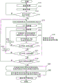
Fig. 11 is a flowchart showing the beamforming processing operation of the reception beamformer unit 104 according to the embodiment.
Fig. 12 is a flowchart showing an acoustic line signal generating operation for observation point Pij in reception beamformer unit 104 according to the embodiment.
Fig. 13 is a schematic diagram for explaining an operation of generating an acoustic line signal with respect to observation point Pij in reception beamformer section 104 according to the embodiment.
FIGS. 14(a) to (c) are schematic diagrams showing the shapes of target regions in comparative examples 1 to 3.
Fig. 15(a) to (d) are ultrasonic images obtained by the reception beam forming of the examples and comparative examples 1 to 3.
Fig. 16(a) to (d) are schematic diagrams showing the relationship between the traveling direction of the ultrasonic beam and the observation point in the examples and comparative examples 1 to 3.
Fig. 17 is a schematic diagram showing the relationship between the reception aperture Rx and the transmission aperture Tx set by the Tx reception aperture setting unit in modification 1.
Fig. 18 is a flowchart showing the beamforming processing operation of the reception beamformer unit of the ultrasonic diagnostic apparatus according to modification 1.
Fig. 19 is a schematic diagram for explaining an operation of generating an acoustic line signal with respect to observation point Pij in the reception beamformer unit of modification 1.
Fig. 20 is a schematic diagram showing another example of the object line group Bx according to the embodiment.
(symbol description)
1000: an ultrasonic diagnostic system; 100: an ultrasonic diagnostic apparatus; 101: a detector; 101 a: a vibrator; 102: a multiplexer section; 103: a transmission beam former section; 1031: a transmission unit; 104. 104A: a reception beam former section; 1040: a receiving section; 1041. 1041A: a phase adjustment addition unit; 1042. 1042A: a target line group setting unit; 1043. 1043A: a receiving opening setting section; 1044: a transmission time calculation unit; 1045: a reception time calculation unit; 1046: a delay amount calculation unit; 1047: a delay processing unit; 1048: a weight calculation unit; 1049: an addition unit; 1140. 1140A: a synthesis unit; 11401. 11401A: an addition processing unit; 11402. 11402A: an amplification processing section; 11403A: a bonding section; 105: an ultrasonic image generating unit; 106: a display unit; 107: a data storage unit; 108: a control unit; 150: an ultrasonic signal processing device.
Detailed Description
A procedure for attaining an embodiment of the invention
The present inventors have made various studies to suppress the reduction in spatial resolution and S/N ratio (hereinafter referred to as "quality of acoustic line signal") of acoustic line signals and reduce the amount of computation in an ultrasonic diagnostic apparatus using the synthetic aperture method.
In general, in the convergent-type transmit beamforming, a wavefront is converged at a certain depth of a subject (hereinafter referred to as "focal depth") to focus an ultrasonic beam. Therefore, the ultrasonic wave is mainly irradiated from a plurality of transducers (hereinafter referred to as "transmission transducer arrays") used for ultrasonic wave transmission to the ultrasonic wave main irradiation region by one ultrasonic wave transmission (transmission event). When the transmission focal point is one point, the ultrasonic main irradiation region is an hourglass clock-shaped region surrounded by two straight lines passing through the transmission focal point from each of the two ends of the bottom line with the transmission transducer array as the bottom line, and the wavefront is in an arc shape centered on the transmission focal point. In addition, not only is the ultrasonic beam focused at one point, but there is also a case where the ultrasonic beam is focused only in a region focused by an amount corresponding to 1.5 transducers to several transducers, for example, in this case, the width of the main ultrasonic irradiation region in the column direction up to the focal depth becomes narrow, and the region deeper than the focal depth becomes wider in the column direction again in the width of the focal region in the column direction below the focal depth. In this case, for convenience of explanation, the center point of the focus region at the focal depth is defined as "focal point". That is, the main irradiation region of the ultrasonic wave has the following shape regardless of whether the focus is focused at one point: the depth of focus is such that the width in the column direction (the direction in which the elements are arranged) is wider as the distance from the depth of focus is longer.
In the synthetic aperture method, since the observation point can be set for the entire ultrasonic main irradiation region in one transmission event, it is preferable that the entire ultrasonic main irradiation region be a target region. Since the entire region in which an ultrasound image is generated in one transmission event (hereinafter referred to as "the target region") cannot be regarded as the target region, a plurality of transmission events having different target regions are performed to generate one frame of ultrasound image. Therefore, from the viewpoint of the utilization efficiency of the ultrasonic waves, the target region in one transmission event is preferably increased in area within the main irradiation region of the ultrasonic waves. In general, in order to improve spatial resolution and signal S/N ratio, it is preferable that the overlap area of the target regions of two consecutive transmission events is large.
However, since the number of observation points included in the target area is proportional to the area of the target area, the amount of calculation for phase modulation and addition and the amount of memory required for storing the acoustic line signal after phase modulation and addition are necessarily proportional to the area of the target area. Therefore, the increase in the area of the target region directly leads to an increase in the storage amount required for the ultrasonic diagnostic apparatus. In addition, if the computation capability of the ultrasonic diagnostic apparatus is insufficient for the computation amount of the phase addition, the frame rate commensurate with the computation capability cannot be exceeded, and therefore, there is a possibility that the time resolution is reduced due to the reduction in the frame rate of the ultrasonic image, and the usability is reduced. Therefore, in order to suppress the decrease in time resolution and the decrease in usability, a processor having high processing capability, such as a high-performance GPU, which can perform the phase adjustment and addition operation at high speed is required, which increases the cost of the ultrasonic diagnostic apparatus.
In order to reduce the amount of computation, it is considered to reduce the number of observation points included in the target region. As a method of reducing the number of observation points, a method of reducing the area of the target region and a method of reducing the density of observation points in the target region are considered. However, when the target region is made small (narrowed) in the depth direction, the region in which an ultrasound image can be generated becomes small in proportion to the area of the target region, and when the observation point density is made low in the depth direction, the distance resolution, which is the spatial resolution in the depth direction, becomes low in proportion to the observation point density. Therefore, the inventors have found a method of suppressing the deterioration of the quality of the acoustic line signal and reducing the number of observation points in the direction in which the transducers are arranged, and have obtained the following idea: by setting a target line group consisting of a plurality of target lines passing through the focal point or its vicinity as a target region, the density of observation points in the direction intersecting the target lines is reduced. This makes it possible to reduce the number of observation points, and to reduce the range resolution and the range of generation of the ultrasonic image because neither the number nor the density of observation points is reduced in the depth direction. Further, as compared with the case where the width of the target region is reduced in the direction in which the transducers of the probe are arranged, it is possible to suppress a decrease in the resolution in the depth direction and the S/N ratio of the acoustic line signal due to a reduction in the overlapping area of the target regions of two consecutive transmission events. This is because, in the object line group of two consecutive transmission events, although the number of overlapping observation points itself decreases, the change in the positional relationship between one observation point and the focal point F and the receiving aperture does not decrease.
Hereinafter, an ultrasonic image processing method and an ultrasonic diagnostic apparatus using the method according to an embodiment will be described in detail with reference to the drawings.
Detailed description of the preferred embodiments
< integral Structure >
Hereinafter, an ultrasonic diagnostic apparatus 100 according to an embodiment will be described with reference to the drawings.
Fig. 1 is a functional block diagram of an ultrasonic diagnostic system 1000 according to an embodiment. As shown in fig. 1, the ultrasonic diagnostic system 1000 includes: a probe 101 having a plurality of transducers 101a that transmits an ultrasonic wave to a subject and receives a reflected wave thereof; an ultrasonic diagnostic apparatus 100 that transmits and receives ultrasonic waves to and from a probe 101 and generates an ultrasonic image based on an output signal from the probe 101; and a display unit 106 for displaying the ultrasonic image on the screen. The probe 101 and the display unit 106 are configured to be connectable to the ultrasonic diagnostic apparatus 100, respectively. Fig. 1 shows a state in which a probe 101 and a display unit 106 are connected to an ultrasonic diagnostic apparatus 100. The probe 101 and the display unit 106 may be inside the ultrasonic diagnostic apparatus 100.
< construction of ultrasonic diagnostic apparatus 100 >
The ultrasonic diagnostic apparatus 100 includes: a multiplexer unit 102 that selects each of the plurality of transducers 101a of the probe 101 to be used for transmission or reception and ensures input/output to/from the selected transducer; a transmission beamformer unit 103 for controlling the timing of applying a high voltage to each transducer 101a of the probe 101 in order to transmit an ultrasonic wave; and a reception beamformer unit 104 for amplifying and a/D converting the electric signals obtained by the plurality of transducers 101a based on the reflected wave of the ultrasonic wave received by the probe 101, and performing reception beamforming to generate an acoustic line signal. Further provided with: an ultrasonic image generation unit 105 that generates an ultrasonic image (B-mode image) based on the output signal from the reception beamformer unit 104; a data storage unit 107 for storing the acoustic line signal output from the reception beamformer unit 104 and the ultrasonic image output from the ultrasonic image generator 105; and a control unit 108 for controlling the respective components.
The multiplexer unit 102, the transmission beamformer unit 103, the reception beamformer unit 104, and the ultrasonic image generator unit 105 constitute an ultrasonic signal processing device 150 as an ultrasonic signal processing circuit.
Each of the elements constituting the ultrasonic diagnostic apparatus 100, for example, the multiplexer unit 102, the transmission beamformer unit 103, the reception beamformer unit 104, the ultrasonic image generation unit 105, and the control unit 108, is implemented by a hardware Circuit such as an FPGA (Field Programmable Gate Array) or an ASIC (application Specific integrated Circuit). Alternatively, the present invention may be implemented by software and a programmable device such as a processor. As the processor, a CPU (Central Processing Unit) and a GPGPU (General-Purpose computing Graphics processor) can be used, and a configuration using a GPU is called a GPGPU (General-Purpose computing Graphics Processing Unit). These components may be one circuit component or an assembly of a plurality of circuit components. In addition, a plurality of components may be combined into one circuit component or an assembly of a plurality of circuit components.
The data storage unit 107 is a computer-readable recording medium, and may be, for example, a flexible disk, a hard disk, an MO, a DVD-RAM, a BD, a semiconductor memory, or the like. The data storage unit 107 may be a storage device externally connected to the ultrasonic diagnostic apparatus 100.
The ultrasonic diagnostic apparatus 100 according to the present embodiment is not limited to the ultrasonic diagnostic apparatus having the configuration shown in fig. 1. For example, the transmission beamformer 103 and the reception beamformer 104 may be directly connected to the transducers 101a of the probe 101 without the multiplexer 102. The probe 101 may be configured to incorporate the transmission beamformer unit 103, the reception beamformer unit 104, or a part thereof. This is not limited to the ultrasonic diagnostic apparatus 100 of the present embodiment, but is also the same in the ultrasonic diagnostic apparatus of other embodiments and modifications to be described later.
< configuration of main part of ultrasonic diagnostic apparatus 100 >
The ultrasonic diagnostic apparatus 100 according to embodiment 1 is characterized by including: a transmission beam former unit 103 for transmitting ultrasonic waves from the transducers 101a of the probe 101; the reception beamformer unit 104 calculates an electric signal obtained from reception of the ultrasound reflected wave by the probe 101, and generates an acoustic line signal for generating an ultrasound image. Therefore, in the present specification, the configurations and functions of the transmission beamformer section 103 and the reception beamformer section 104 will be mainly described. The same configuration as that used in a known ultrasonic diagnostic apparatus can be applied to the configuration other than the transmission beamformer unit 103 and the reception beamformer unit 104, and the beamformer unit of the present embodiment can be replaced with the beamformer unit of the known ultrasonic diagnostic apparatus and used.
The configurations of the transmission beamformer section 103 and the reception beamformer section 104 are explained below.
1. Transmission beam former section 103
The transmission beam former unit 103 is connected to the probe 101 via the multiplexer unit 102, and controls timing of applying a high voltage to each of the plurality of transducers included in a transmission aperture Tx formed by a transmission transducer array corresponding to all or a part of the plurality of transducers 101a present in the probe 101 in order to transmit an ultrasonic wave from the probe 101. The transmission beamformer unit 103 is constituted by a transmission unit 1031.
The transmission unit 1031 performs transmission processing for supplying a pulse-shaped transmission signal for transmitting an ultrasonic beam to each transducer included in the transmission opening Tx among the plurality of transducers 101a present in the probe 101, in accordance with a transmission control signal from the control unit 108. Specifically, the transmission unit 1031 includes, for example, a clock generation circuit, a pulse generation circuit, and a delay circuit. The clock generation circuit is a circuit that generates a clock signal for determining the transmission timing of the ultrasonic beam. The pulse generating circuit is a circuit for generating a pulse signal for driving each transducer. The delay circuit is a circuit for setting a delay time for transmission timing of an ultrasonic beam for each transducer and performing ultrasonic beam focusing by delaying transmission of the ultrasonic beam by an amount corresponding to the delay time.
The transmission unit 1031 repeats ultrasonic transmission while sequentially moving the transmission openings Tx in the column direction for each ultrasonic transmission, and performs ultrasonic transmission from all the transducers 101a present in the probe 101. That is, in the present embodiment, the transmission opening Tx is sequentially shifted by an amount corresponding to one transducer for each ultrasonic transmission. Information indicating the positions of the transducers included in the transmission opening Tx is output to the data storage 107 via the control unit 108. For example, when the number of all the transducers 101a present in the probe 101 is 192, for example, 20 to 100 may be selected as the number of transducer rows constituting the transmission opening Tx, or a configuration may be adopted in which the transducer rows are shifted by an amount corresponding to one transducer for each ultrasonic transmission. Hereinafter, the ultrasonic transmission from the same transmission opening Tx by the transmission unit 1031 is referred to as a "transmission event".
Fig. 2 is a schematic diagram showing a propagation path of the ultrasonic transmission wave formed by the transmission beam former section 103. In a certain transmission event, a row of the array-like transducers 101a (transmission transducer row) contributing to ultrasonic transmission is shown as a transmission aperture Tx. The column length of the transmission aperture Tx is referred to as a transmission aperture length.
In the transmission beamformer section 103, the transmission timing of each transducer is controlled so that the transmission timing is delayed as the transducer is located at the center of the transmission aperture Tx. Thereby, the ultrasonic transmission waves transmitted from the transducer array in the transmission opening Tx are in the following states: at a certain depth (Focal depth) of the subject, the wavefronts converge (converge) at one point, i.e., at the transmit focus F (Focal point). The depth (Focal depth) of the transmission Focal point F (hereinafter referred to as "Focal depth") can be arbitrarily set. The wavefront focused at the transmission focal point F is diffused again, and the ultrasonic transmission wave propagates in an hourglass clock-shaped space defined by two intersecting straight lines with the transmission focal point F as a node and the transmission aperture Tx as a base. That is, the ultrasonic wave radiated at the transmission opening Tx gradually decreases its spatial width (horizontal axis direction in the figure), is smallest at the transmission focal point F, and increases its width again as it goes to a deeper portion (upper portion in the figure) than it, and spreads and propagates. The region of the hourglass clock shape is the main ultrasonic irradiation region Ax. As described above, the ultrasonic transmission wave may be transmitted so that the ultrasonic main irradiation region Ax converges in the vicinity of the transmission focal point F at one point.
2. Structure of receive beamformer section 104
The reception beamformer unit 104 generates an acoustic line signal from the electric signals obtained by the plurality of transducers 101a based on the reflected wave of the ultrasonic wave received by the probe 101. The term "sound ray signal" refers to a signal obtained by performing phase adjustment and addition processing on a certain observation point. The phase adjustment and addition processing will be described later. Fig. 3 is a functional block diagram showing the configuration of the receive beamformer section 104. As shown in fig. 3, the reception beamformer section 104 includes a reception section 1040, a phasing and addition section 1041, and a combining section 1140.
The configuration of each part constituting the receive beamformer section 104 will be described below.
(1) Receiving section 1040
The receiving section 1040 is a circuit as follows: the multiplexer unit 102 is connected to the probe 101, and generates a reception signal (RF signal) obtained by amplifying an electric signal obtained by receiving an ultrasonic reflected wave from the probe 101 and performing AD conversion in synchronization with a transmission event. The reception signal is generated in time series in the order of the transmission events and output to the data storage unit 107, and the reception signal is stored in the data storage unit 107.
Here, the reception signal (RF signal) is a digital signal obtained by a/D converting an electric signal obtained by converting reflected ultrasonic waves received by each transducer, and forms a sequence of signals that are continuous in the transmission direction (depth direction of the subject) of the ultrasonic waves received by each transducer.
In the transmission event, as described above, the transmission unit 1031 causes each of the plurality of transducers included in the transmission opening Tx among the plurality of transducers 101a present in the probe 101 to transmit an ultrasonic beam. On the other hand, the receiving unit 1040 generates a sequence of reception signals for each transducer from reflected ultrasonic waves obtained by each transducer corresponding to some or all of the plurality of transducers 101a present in the probe 101 in synchronization with the transmission event. Here, the transducer that receives the reflected ultrasonic wave is referred to as a "wave receiving transducer". The number of wave receiving oscillators is preferably larger than the number of oscillators included in the transmission aperture Tx. The number of wave-receiving oscillators may be the number of all oscillators 101a present in the probe 101.
The transmission unit 1031 repeats ultrasonic transmission while sequentially moving the transmission openings Tx in the column direction in synchronization with the transmission event, and performs ultrasonic transmission from the entire plurality of transducers 101a present in the probe 101. The receiving unit 1040 generates a sequence of reception signals for each reception oscillator in synchronization with a transmission event, and stores the generated reception signals in the data storage unit 107.
(2) Phase adjustment addition unit 1041
The phase adjustment and addition unit 1041 sets the target line group Bx in which the sub-frame acoustic line signal is generated in the subject in synchronization with the transmission event. Next, for each of a plurality of observation points Pij existing on the target line group Bx, a phase adjustment and addition operation is performed on the received signal sequence received by each receiver element Rk from the observation point. The phase adjustment and addition unit 1041 is a circuit that generates sub-frame acoustic line signals by calculating the sequence of acoustic line signals at each observation point. Fig. 4 is a functional block diagram showing the configuration of the phasing and adding unit 1041. As shown in fig. 4, the phasing and adding unit 1041 includes a target line group setting unit 1042, a reception aperture setting unit 1043, a transmission time calculation unit 1044, a reception time calculation unit 1045, a delay amount calculation unit 1046, a delay processing unit 1047, a weight calculation unit 1048, and an adding unit 1049.
The following describes the configuration of each part constituting the phasing and adding unit 1041.
i) Target line group setting unit 1042
The target line group setting unit 1042 sets the target line group Bx in which the sub-frame acoustic line signal is generated in the subject. The "target line group" is an area on a signal to be subjected to generation of a sub-frame sound ray signal in the subject in synchronization with a transmission event, and a sound ray signal is generated with respect to an observation point Pij on the target line group Bx. For the sake of convenience of calculation, the target line group Bx is set as a set of observation target points for generating the sound ray signal in synchronization with one transmission event.
Here, the "subframe acoustic line signal" is a set of acoustic line signals generated from one transmission event for all observation points Pij existing on the target line group Bx. The "subframe" is a unit for obtaining and forming a summed signal corresponding to all observation points Pij existing on the target line group Bx in one transmission event. The result obtained by obtaining a plurality of subframes different in time is synthesized as a frame.
The target line group setting unit 1042 sets the target line group Bx based on the information indicating the position of the transmission aperture Tx acquired from the transmission beamformer unit 103 in synchronization with the transmission event.
Fig. 5 is a schematic diagram showing the object line group Bx. As shown in fig. 5, the target line group Bx is present in the ultrasonic main irradiation region Ax and is constituted by a plurality of target lines BL1 to BL 7. Each object line is a straight line passing through or near the focal point F. The subject lines BL1 and BL7 correspond to the outer contour lines of the ultrasound main irradiation region Ax, respectively, and the subject line BL4 is present on the transmission aperture center axis Txo. For convenience, the outline of the main ultrasonic irradiation region Ax is defined by two lines, i.e., a straight line passing through one end of the transmission aperture Tx and the focal point F, and a straight line passing through the other end of the transmission aperture Tx and the focal point F. The angles formed by adjacent target lines among the target lines BL1 to BL7 are substantially equal. That is, observation points existing on an arc centered on the focal point F are arranged at equal intervals. In addition, the distance di between the observation point Pij and P (i +1) j on the adjacent object lines BL2 and BL3 is smaller than the distance dj between the observation point Pij and Pi (j +1) j on the same object line BL2, except for the case where the distance Pij from the focal point F is smaller than the predetermined distance. The distance di is at least twice, preferably four times or more, and more preferably eight times or more the distance dj. Thus, the observation points are uniformly arranged over substantially the entire ultrasonic main irradiation region Ax so as to have a high density in the depth direction and a low density in the direction in which the transducers are arranged (the circumferential direction around the focal point F). Here, the predetermined distance represents a range in which the distance between a point on the object line and a point on the adjacent object line is smaller than the interval of the observation points along the object line. For example, when an angle formed by adjacent object lines is θ, the predetermined distance dp satisfies the following expression.
di=2·dp·sin(θ/2)
The shape of the object line group Bx is not limited to the above, and for example, the distances of positions in contact with the transmission transducer rows may be set to be equal intervals in the object lines BL1 to BL 7. The object line group Bx is composed of seven object lines, but this is an example, and the number of object lines may be set arbitrarily as long as it is within a range of three or more.
Further, each observation point Pij is assumed to be present on the target line group Bx, but for example, a part or all of the observation points may be set at a position close to the target line. For example, the observation point Pij can be represented by the direction in which the transducers are arranged (x direction) and the depth direction (y direction), and can be present at a grid point of orthogonal coordinates in which the center of each transducer is a grid point. This is because, by making such a structure, the transducers having the same x coordinate are always present at each observation point Pij, and therefore, the quality of the sound ray signal can be improved. In this case, the object line is not necessarily parallel to the y direction, and therefore the object line may not pass through the grid point at a position where the observation point is desired to be set. In such a case, the observation point is not provided directly above the target line, but is provided at a square point close to the target line. For example, the actual coordinates of the observation points to be set on the object line are defined by rounding the coordinates of the observation points by a predetermined number of digits. Specifically, the observation point is determined as follows. In the direction in which the transducers are arranged (x direction), the number of transducers of the probe is 192, the position of the transducer at one end of the transducer array of the probe is 0, and the position of the transducer at the other end is 191. In the depth direction, the position of the transducer row is defined as y equal to 0, and a point having a depth corresponding to one transducer of the probe is defined as y equal to 1. If the coordinate of the focal point F is set to (64, 1000) and a line of objects passing through the coordinate (31, 0) is set, the line of objects is expressed by the following formula.
y=(1000/33)·(x-31)
At this time, for example, when it is desired to set an observation point at a depth of y 1500, (80.5, 1500). In this case, the observation point may be (81, 1500). This makes it possible to use the element with x of 81 as a reference in the phasing addition operation, and thus to improve the quality of the acoustic line signal. Further, the position at which the observation point is actually set is not limited to the above, and the observation point to be set on the target line group Bx may be arbitrarily set as long as a close point which is computationally preferable to round the value of the coordinate is set as the actual observation point.
The set target line group Bx is output to the transmission time calculation unit 1044, the reception time calculation unit 1045, and the delay processing unit 1047.
ii) a receiving opening setting part 1043
The reception aperture setting unit 1043 is a circuit: the reception aperture Rx is set by selecting, as reception transducers, transducer rows (reception transducer rows) corresponding to a part of the plurality of transducers present in the probe 101 and having a row center matching the row center of the transducer row included in the transmission aperture Tx, based on a control signal from the control unit 108 and information indicating the position of the transmission aperture Tx from the transmission beam former unit 103.
Reception aperture setting unit 1043 selects the reception aperture Rx transducer array such that the array center matches transducer Xk spatially closest to observation point Pij. Fig. 6 is a schematic diagram showing the relationship between the reception aperture Rx and the transmission aperture Tx set by the reception aperture setting unit 1043. As shown in fig. 6, the reception aperture Rx transducer array is selected such that the center of the array of the reception aperture Rx transducer array matches the transducer Xk spatially closest to the observation point Pij. Therefore, the position of the reception aperture Rx is determined by the position of the observation point Pij and does not change depending on the position of the transmission aperture Tx that changes in synchronization with the transmission event. That is, even in the case of different transmission events, in the process of generating the acoustic line signal with respect to the observation point Pij at the same position, the phase adjustment and addition are performed based on the reception signal acquired by the reception transducer Rk in the same reception aperture Rx.
In order to receive the reflected wave from the entire ultrasonic main irradiation region, the number of transducers included in the reception aperture Rx is preferably set to be equal to or greater than the number of transducers included in the transmission aperture Tx in the corresponding transmission event. The number of transducer arrays constituting the reception aperture Rx may be 32, 64, 96, 128, 192, for example.
In response to the transmission event, the reception aperture Rx is set at least as many times as the transmission event. The setting of the reception aperture Rx may be performed in synchronization with the transmission event, or may be performed collectively by the number of transmission events after all the transmission events have ended.
The information indicating the position of the selected reception aperture Rx is output to the data storage unit 107 via the control unit 108.
The data storage unit 107 outputs information indicating the position of the reception aperture Rx and the reception signal corresponding to the reception transducer to the transmission time calculation unit 1044, the reception time calculation unit 1045, the delay processing unit 1047, and the weight calculation unit 1048.
iii) Transmission time calculation Unit 1044
The transmission time calculation unit 1044 is a circuit that calculates the transmission time at which the transmitted ultrasonic wave reaches the observation point P in the subject. In response to the transmission event, the transmission time at which the transmitted ultrasonic wave reaches the observation point Pij in the subject is calculated for any observation point Pij present on the target line group Bx based on the information indicating the position of the transducer included in the transmission aperture Tx acquired from the data storage 107 and the information indicating the position of the target line group Bx including the main irradiation region Ax of the ultrasonic wave acquired from the target line group setting unit 1042.
Fig. 7 is a schematic diagram for explaining propagation paths of ultrasonic waves radiated from the transmission aperture Tx and reflected at an observation point Pij at an arbitrary position on the object line group Bx to reach the reception transducer Rk located in the reception aperture Rx. Fig. 7(a) shows a case where the depth of observation point Pij is equal to or greater than the focal depth, and fig. 7(b) shows a case where observation point Pij is shallower than the focal depth.
The transmission wave radiated from the transmission aperture Tx is wavefront-converged at the transmission focal point F by the path 401 to be diffused again. The transmission wave reaches the observation point Pij on the way to converge or diverge, and if the acoustic impedance changes at the observation point Pij, a reflected wave is generated, which returns to the reception oscillator Rk in the reception opening Rx in the probe 101. Since the transmission focal point F is defined as a design value of the transmission beamformer unit 103, the length of the path 402 between the transmission focal point F and an arbitrary observation point Pij can be geometrically calculated.
The method of calculating the transmission time will be described in more detail below.
First, a case where the depth of observation point Pij is equal to or greater than the focal depth will be described with reference to fig. 7 (a). When the depth of observation point Pij is equal to or greater than the focal depth, the depth is calculated as a case where the transmission wave radiated from transmission opening Tx passes through path 401 to reach transmission focal point F, and passes through path 402 from transmission focal point F to reach observation point Pij. Therefore, the sum of the time of the transmission wave passing through the path 401 and the time of the transmission wave passing through the path 402 is the transmission time. A specific calculation method is, for example, obtained by dividing the entire path length obtained by adding the length of the path 401 and the length of the path 402 by the transmission speed of the ultrasonic wave in the subject.
On the other hand, a case where the observation point Pij is shallower than the focal depth will be described with reference to fig. 7 (b). When observation point Pij is shallower than the focal depth, the time at which the transmission wave radiated from transmission opening Tx reaches transmission focal point F through path 401 is the same as the time at which the transmission wave reaches transmission focal point F through path 402 after reaching observation point Pij through path 404. That is, the transmission time is a value obtained by subtracting the time of the transmission wave passing through the path 402 from the time of the transmission wave passing through the path 401. A specific calculation method is, for example, obtained by dividing a path length difference obtained by subtracting the length of the path 402 from the length of the path 401 by the transmission speed of the ultrasonic wave in the subject.
In addition, as for the transmission time when observation point Pij is the depth of focus, the same calculation method as in the case when observation point Pij is deeper than the depth of focus, that is, a calculation method of adding the time when the transmission wave passes through path 401 and the time when the transmission wave passes through path 402 is used. However, the same calculation method as that in the case where observation point Pij is shallower than the focal depth, that is, the calculation method of subtracting the time of passing through path 402 from the time of passing through path 401 of the transmission wave may be used. The reason for this is that the length of the path 402 is 0, and therefore, the time taken to pass through the path 401 coincides with the time calculated by any method.
The transmission time calculation unit 1044 calculates the transmission time at which the transmitted ultrasonic wave reaches the observation point Pij in the subject for all the observation points Pij on the target line group Bx for one transmission event, and outputs the transmission time to the delay amount calculation unit 1046.
iv) a reception time calculation unit 1045
The reception time calculator 1045 is a circuit that calculates a reception time at which the reflected wave from the observation point P reaches each of the reception oscillators Rk included in the reception aperture Rx. In response to the transmission event, the reception time of each of the reception transducers Rk which has been reflected by the observation point Pij in the subject and reached the reception opening Rx is calculated for an arbitrary observation point Pij present on the target line group Bx based on the information indicating the position of the reception transducer Rk acquired from the data storage unit 107 and the information indicating the position of the target line group Bx acquired from the target line group setting unit 1042.
As described above, if the acoustic impedance changes at observation point Pij, the transmission wave that has reached observation point Pij generates a reflected wave that returns to each of the reception oscillators Rk in the reception aperture Rx in the probe 101. Since the position information of each receiver Rk in the reception aperture Rx is acquired from the data storage unit 107, the length of the path 403 from an arbitrary observation point Pij to each receiver Rk can be geometrically calculated.
The reception time calculator 1045 calculates the reception time at which the transmitted ultrasonic wave is reflected at the observation point Pij and reaches each receiver element Rk for all observation points Pij present on the target line group Bx for one transmission event, and outputs the result to the delay amount calculator 1046.
v) delay amount calculation unit 1046
The delay amount calculation unit 1046 is a circuit that calculates the total propagation time to each of the reception elements Ri in the reception aperture Rx from the transmission time and the reception time, and calculates the delay amount applied to the column of the reception signal for each of the reception elements Rk from the total propagation time. The delay amount calculator 1046 acquires the transmission time at which the ultrasonic wave transmitted from the transmission time calculator 1044 reaches the observation point Pij and the reception time at which the ultrasonic wave is reflected at the observation point Pij and reaches each receiver Rk. Further, the total propagation time until the transmitted ultrasonic wave reaches each reception transducer Rk is calculated, and the delay amount for each reception transducer Rk is calculated from the difference in the total propagation time for each reception transducer Rk. The delay amount calculation unit 1046 calculates the delay amount applied to the column of the reception signal for each reception element Ri for all the observation points Pij present on the target line group Bx, and outputs the delay amount to the delay processing unit 1047.
vi) delay processing unit 1047
The delay processing unit 1047 is a circuit that recognizes a reception signal corresponding to a delay amount for each reception transducer Rk from a row of reception signals for the reception transducers Rk in the reception aperture Rx as a reception signal corresponding to each reception transducer Rk based on reflected ultrasonic waves from the observation point Pij.
The delay processing unit 1047 receives as input information indicating the position of the reception transducer Rk from the reception aperture setting unit 1043, a reception signal corresponding to the reception transducer Rk from the data storage unit 107, information indicating the position of the acquired target line group Bx from the target line group setting unit 1042, and a delay amount applied to the column of the reception signal for each reception transducer Rk from the delay amount calculation unit 1046, in accordance with the transmission event. Further, the received signal corresponding to the time obtained by subtracting the delay amount for each of the receiver elements Rk is regarded as the received signal based on the reflected wave from the observation point Pij, based on the column of the received signal corresponding to each of the receiver elements Rk, and is output to the addition unit 1049.
vii) weight calculation unit 1048
The weight calculation unit 1048 is a circuit that calculates the number of weight steps (reception apodization) for each reception transducer Rk so that the weight for the transducer located at the center of the reception aperture Rx in the column direction becomes maximum.
As shown in fig. 6, the weighting series is a series of weighting coefficients applied to the reception signals corresponding to the respective transducers in the reception aperture Rx. The weight series is distributed symmetrically around the transmission focal point F. The shape of the distribution of the weight series may be a hamming window, a hanning window, a rectangular window, or the like, and the shape of the distribution is not particularly limited. The weighting series is set so that the weighting for the transducer located at the center of the column of the reception aperture Rx is the largest, and the central axis of the distribution of the weighting coincides with the reception aperture central axis Rxo. The weight calculation unit 1048 receives the information indicating the position of the receiver oscillator Rk output from the receiver aperture setting unit 1043 as an input, calculates the number of weight steps for each receiver oscillator Rk, and outputs the result to the addition unit 1049.
viii) addition unit 1049
The adder 1049 is a circuit that receives the reception signals output from the delay processing unit 1047 and recognized in association with the respective reception transducers Rk, adds them, and generates an acoustic line signal obtained by phase-modulating and adding the reception signals with respect to the observation point Pij. Alternatively, the number of weighting levels for each receiver element Rk output from the weight calculation unit 1048 may be further input, and the received signal recognized in association with each receiver element Rk may be multiplied by the weighting for each receiver element Rk to be added, thereby generating an acoustic line signal for the observation point Pij. By adjusting the phase of the reception signal detected by each reception oscillator Rk located in the reception aperture Rx in the delay processing unit 1047 and performing addition processing in the addition unit 1049, the signal S/N ratio can be increased by superimposing the reception signal received by each reception oscillator Rk on the reflection wave from the observation point Pij, and the reception signal from the observation point Pij can be extracted.
The acoustic line signals can be generated for all the observation points Pij on the target line group Bx from one transmission event and the processing associated therewith. Further, by repeating the ultrasonic transmission while sequentially moving the transmission aperture Tx in the column direction in synchronization with the transmission event, the ultrasonic transmission is performed from all the transducers 101a present in the probe 101, thereby generating a frame acoustic line signal which is an acoustic line signal synthesized for one frame.
Hereinafter, the sound ray signal synthesized for each observation point constituting the frame sound ray signal is referred to as a "synthesized sound ray signal".
The addition unit 1049 generates sound ray signals for the sub-frames of all the observation points Pij existing on the target line group Bx in synchronization with the transmission event. The generated sound ray signal of the sub-frame is output to the data storage unit 107 and stored.
(5) Combining part 1140
The synthesizing unit 1140 is a circuit that synthesizes a frame audio signal from the sub-frame audio signal generated in synchronization with the transmission event. Fig. 8 is a functional block diagram showing the configuration of the combining unit 1140. As shown in fig. 8, the combining unit 1140 includes an addition processing unit 11401 and an amplification processing unit 11402.
The structure of each part constituting the combining part 1140 will be described below.
i) Addition processing unit 11401
The addition processing unit 11401 reads the plurality of sub-frame sound ray signals held in the data holding unit 107 after generation of a series of sub-frame sound ray signals for synthesizing the frame sound ray signal is completed. Then, the plurality of sub-frame sound ray signals are added by using as an index the position of the observation point Pij at which the sound ray signal included in each sub-frame sound ray signal is acquired, thereby generating a synthesized sound ray signal for each observation point and synthesizing the frame sound ray signals. Therefore, the sound ray signals for the observation points at the same position included in the plurality of sub-frame sound ray signals are added to generate a synthesized sound ray signal.
Fig. 9 is a schematic diagram showing a process of synthesizing the synthesized sound ray signal in the addition processing unit 11401. As described above, the transducers used in the transmission transducer array (transmission aperture Tx) are shifted by one transducer in the transducer array direction in synchronization with the transmission event, and ultrasonic transmission is performed sequentially. Therefore, the target line group Bx based on different transmission events is also shifted in position by one element in the same direction for each transmission event. The frame sound ray signals covering all the object ray groups Bx are synthesized by adding a plurality of sub-frame sound ray signals using the position of the observation point Pij where the sound ray signals included in each sub-frame sound ray signal are acquired as an index.
Further, since the values of the sound ray signals in the sound ray signals of the respective sub-frames are added to the observation points Pij existing across the plurality of object ray groups Bx at different positions, the synthesized sound ray signal has a value large according to the degree of crossing. Hereinafter, the number of times included in the target line group Bx having different observation points Pij is referred to as the "number of superposition", and the maximum value of the number of superposition in the transducer array is referred to as the "maximum number of superposition".
In the present embodiment, the target line group Bx is present in the hourglass clock-shaped region. Therefore, as shown in fig. 10(a), since the number of superimposes and the maximum number of superimposes vary in the depth direction of the subject, the value of the synthesized acoustic line signal also varies in the depth direction. However, in the embodiment of the present invention, when the number of target line groups is 11, for example, the maximum number of superposition is limited to 11 at the maximum.
When the position of the observation point Pij at which the sound ray signals included in the sound ray signals of the respective subframes are acquired is added as an index, the position of the observation point Pij may be weighted as an index and added.
The synthesized frame sound ray signal is output to the amplification processing unit 11402.
ii) amplification processing section 11402
As described above, the value of the synthesized sound ray signal changes in the depth direction of the subject. To compensate for this, the amplification processing unit 11402 performs amplification processing of multiplying each synthesized sound ray signal by an amplification factor determined according to the number of times of addition in synthesizing the synthesized sound ray signals included in the frame sound ray signal.
Fig. 10(b) is a schematic diagram showing an outline of the enlargement processing in the enlargement processing unit 11402. As shown in fig. 10(b), since the maximum superposition number varies in the depth direction of the subject, the synthesized sound ray signal is multiplied by the amplification factor varying in the depth direction of the subject determined based on the maximum superposition number to compensate for the variation. This eliminates the factor of fluctuation of the synthesized sound ray signal due to the change in the number of superimposed signals in the depth direction, and makes the values of the amplified synthesized sound ray signal uniform in the depth direction.
Further, the synthesized acoustic line signal may be multiplied by an amplification factor that changes in the transducer array direction and is determined according to the number of superposition. When the number of superimposed signals in the transducer array changes, the factor of the change is eliminated, and the value of the synthesized sound ray signal after amplification processing is made uniform in the transducer array.
Further, a signal obtained by performing amplification processing on the generated synthesized sound ray signal for each observation point may be used as the frame sound ray signal.
< action >
The operation of the ultrasonic diagnostic apparatus 100 configured as described above will be described.
Fig. 11 is a flowchart showing the beamforming processing operation of the reception beamformer unit 104.
First, in step S101, the transmission unit 1031 performs a transmission process (transmission event) of supplying a transmission signal for transmitting an ultrasonic beam to each transducer included in the transmission opening Tx among the plurality of transducers 101a present in the probe 101.
Next, in step S102, the receiving unit 1040 generates a reception signal from the electric signal obtained by receiving the ultrasonic reflected wave from the probe 101, outputs the reception signal to the data storage unit 107, and stores the reception signal in the data storage unit 107. It is determined whether or not the ultrasonic wave transmission is completed from all the transducers 101a present in the probe 101 (step S103). If the transmission is not completed, the process returns to step S101, and the transmission opening Tx is shifted in the column direction by an amount corresponding to one transducer to perform a transmission event, and if the transmission is completed, the process proceeds to step S201.
Next, in step S210, the target line group setting unit 1042 sets the target line group Bx based on the information indicating the position of the transmission opening Tx in synchronization with the transmission event. In the first loop, the target line group Bx obtained from the transmission aperture Tx in the first transmission event is set.
Then, the process proceeds to observation point synchronization type beamforming processing (step S220(S221 to S228)). In step S220, first, the coordinates ij indicating the position of the observation point Pij are initialized to the minimum value on the object line group Bx (steps S221 and S222), and the reception aperture setting unit 1043 selects the reception aperture Rx element row so that the row center matches the element Xk spatially closest to the observation point Pij (step S223).
Next, a sound ray signal is generated with respect to observation point Pij (step S224).
Here, an operation of generating an acoustic line signal with respect to observation point Pij in step S224 will be described. Fig. 12 is a flowchart showing an acoustic line signal generating operation for observation point Pij in reception beamformer 104. Fig. 13 is a schematic diagram for explaining an operation of generating an acoustic line signal with respect to observation point Pij in reception beamformer 104.
First, in step S2241, the transmission time calculation unit 1044 calculates the transmission time at which the transmitted ultrasonic wave reaches the observation point Pij in the subject with respect to an arbitrary observation point Pij present on the target line group Bx. (1) When the depth of observation point Pij is equal to or greater than the focal depth, the transmission time can be calculated by dividing the length of a path (401+402) that is geometrically determined from reception transducer Rk in reception opening Rx to observation point Pij via transmission focal point F by the sound velocity cs of the ultrasonic wave, and (2) when observation point Pij is shallower than the focal depth, the transmission time can be calculated by dividing the length of the difference (401-.
Next, the coordinates k indicating the positions of the reception transducers Rk in the reception aperture Rx, which are obtained from the reception aperture Rx, are initialized to the minimum value in the reception aperture Rx (step S2242), and the reception time of the transmitted ultrasonic wave reflected at the observation point Pij in the subject and reaching the reception transducer Rk of the reception aperture Rx is calculated (step S2243). The reception time can be calculated by dividing the length of the geometrically determined path 403 from the observation point Pij to the reception transducer Rk by the sound velocity cs of the ultrasonic wave. Further, a total propagation time until the ultrasonic wave transmitted from the transmission aperture Tx is reflected at the observation point Pij and reaches the reception transducer Rk is calculated from the sum of the transmission time and the reception time (step S2244), and a delay amount for each reception transducer Rk is calculated from a difference in the total propagation time for each reception transducer Rk in the reception aperture Rx (step S2245).
It is determined whether or not the calculation of the delay amount is completed for all the reception oscillators Rk present in the reception aperture Rx (step S2246), and if not completed, the coordinates k are incremented (step S2247), and further the calculation of the delay amount is performed for the reception oscillators Rk (step S2243), and if completed, the routine proceeds to step S2248. At this stage, the delay amount of arrival of the reflected wave from the observation point Pij is calculated for all the reception oscillators Rk present in the reception aperture Rx.
In step S2248, the delay processing unit 1047 recognizes a received signal corresponding to a time obtained by subtracting the delay amount for each of the receiver elements Rk from the row of received signals corresponding to the receiver elements Rk in the reception aperture Rx as a received signal based on the reflected wave from the observation point Pij.
Next, the weight calculation unit 1048 calculates the number of weight steps for each reception transducer Rk so that the weight for the transducer located at the center of the column of the reception aperture Rx becomes maximum (step S2249). The adder 1049 multiplies the received signal recognized in association with each receiver Rk by the weight for each receiver Rk, generates an acoustic line signal for the observation point Pij (step S2250), and outputs the acoustic line signal for the generated observation point Pij to the data storage 107 for storage (step S2251).
Next, returning to fig. 11, step S227 is repeated by incrementing the coordinate ij, and a sound ray signal is generated for all observation points Pij ("·" in fig. 13) of the coordinate ij located on the object line group Bx. It is determined whether or not generation of a sound ray signal is completed for all observation points Pij existing on the object line group Bx (steps S225 and S227), and if not completed, the coordinates ij are incremented (steps S226 and S228), and a sound ray signal is generated for the observation points Pij (step S224), and if completed, the process proceeds to step S230. At this stage, the sound ray signals of the sub-frames of all the observation points Pij existing on the target line group Bx associated with the one transmission event are generated and output to the data storage unit 107 to be stored.
Next, it is determined whether or not the generation of the sound ray signal of the subframe is completed for all the transmission events (step S230), and if not, the procedure returns to step S210, where the coordinates ij representing the position of the observation point Pij are initialized to the minimum value on the target line group Bx obtained from the transmission aperture Tx in the next transmission event (steps S221 and S222), and the reception aperture Rx is set (step S223), and if so, the procedure proceeds to step S301.
Next, in step S301, the addition processing unit 11401 reads the plurality of sub-frame sound ray signals held in the data holding unit 107, adds the plurality of sub-frame sound ray signals using the position of the observation point Pij as an index, generates a synthesized sound ray signal for each observation point Pij, and synthesizes the synthesized sound ray signals into a frame sound ray signal. Next, the amplification processing unit 11402 multiplies each synthesized sound ray signal by an amplification factor determined according to the number of times of addition of each synthesized sound ray signal included in the frame sound ray signal (step S302), outputs the amplified frame sound ray signal to the ultrasonic image generation unit 105 and the data storage unit 107 (step S303), and ends the processing.
< effects of receive beamforming >
Hereinafter, the quality of an ultrasonic image is compared between the reception beamforming of the embodiment and the three reception beamforming as the comparative example, and the effects of the embodiment will be described.
(1) Receive beamforming
In the embodiment, the object line group Bx is composed of a plurality of object lines. One of the object lines is located on the transmission opening center axis Txo, and two object lines are located on the outer periphery of the main ultrasonic irradiation region Ax. In addition, all angles formed by two adjacent object lines are predetermined angles d.
In comparative example 1 shown in fig. 14(a), the target region Bx1 is formed only by a straight line passing through the focal point F and orthogonal to the direction in which the transducers of the probe are arranged. That is, the receive beamforming is not performed using the synthetic aperture method. In comparative example 1, the transmission time may be calculated from only the depth of the observation point. In addition, in the observation point on the target area Bx1 shown in comparative example 1, the transmission time of the embodiment completely coincides with the transmission time obtained by the conventional technique based only on the depth of the observation point, and therefore, the obtained ultrasonic image is not affected by the difference in the calculation method. Since the number of observation points is the same as the number of observation points on one object line in the embodiment, the amount of phase adjustment and addition is more than 0.1 times and less than 0.4 times that in the embodiment.
In comparative example 2 shown in fig. 14(b), the target region Bx2 is a region including the focal point F and having a width narrower in the direction in which the transducers of the probe are arranged (x direction) than the main ultrasonic irradiation region Ax. The observation point density of the object region Bx2 is equal to the observation point density along the direction of the object line in the object line group Bx, and the number of observation points Pij included in the object region Bx2 is equal to the number of observation points Pij included in the object line group Bx of the embodiment. In other words, the ratio of the angular range of the target region Bx2 to the angular range of the main ultrasonic irradiation region Ax is equal to the ratio of the observation point density of the direction orthogonal to the target line in the target line group Bx to the observation point density of the direction along the target line. The number of observation points is equal to that of the embodiment, and the amount of phase modulation addition is also completely the same as that of the embodiment.
In comparative example 3 shown in fig. 14(c), the target region Bx3 is the entire region of the ultrasound main irradiation region Ax. Further, the observation point density of the object region Bx3 is equal to the observation point density of the object region Bx2 and the observation point density of the orientation along the object line in the object line group Bx. That is, the ratio of the number of observation points of the object line group Bx and the object region Bx2 to the number of observation points of the object region Bx3 is equal to the ratio of the angular range of the object region Bx2 to the angular range of the main ultrasonic irradiation region Ax, and is equal to the ratio of the observation point density in the object line group Bx in the direction orthogonal to the object line to the observation point density in the direction along the object line. In the embodiment, the number of observation points is increased so that the observation point density in the direction orthogonal to the object line is the same as the observation point density in the direction along the object line, and the number of observation points is made to match the above state.
(2) Quality of ultrasonic image
Fig. 15 shows an ultrasound image (B-mode tomographic image) obtained by imaging the same virtual subject (phantom) by the receive beam forming in the example and comparative examples 1 to 3. FIG. 15(c) corresponds to the example, and FIGS. 15(a), (b), and (d) correspond to comparative examples 1 to 3, respectively. The traveling direction of the ultrasonic beam is a direction from top to bottom in the figure.
As shown in fig. 15(a), in comparative example 1, the farther from the focal depth (depth of the bright spots in a circular shape), the more the bright spots in a circular shape are spread in the direction in which the transducers are arranged, and the larger the depth, the more the noise, and the less clear the image. This is considered to be that the farther from the focal point F, the more misaligned the focusing of the ultrasonic beam, and the amplitude of the transmission ultrasonic wave decreases so that the disorder of the phase becomes large.
On the other hand, as shown in fig. 15(d), in comparative example 3, although the image becomes dark at the deepest portion, the circular bright spots hardly ooze out, and the image becomes clear in the entire region. This is considered to be because the resolution and S/N ratio of the sound ray signals are improved by virtual beamforming in which frame sound ray signals acquired by a plurality of transmission events are combined, the sound ray signals are intensified and noise components are cancelled.
In addition, in comparative example 2 and example, the following results were obtained. The ultrasonic image of comparative example 2 is fig. 15(b), and the ultrasonic image of the example is fig. 15 (c). As shown in fig. 15(c), in the example, although the noise at the deep part was larger than that in comparative example 3, the bright spots in the circular shape hardly appeared, and a clear image was obtained in the entire area. On the other hand, as shown in fig. 15(b), although the noise at the depth is weaker in comparative example 2 than in comparative example 1, the bright points to be rounded are more likely to be spread in the direction in which the transducers are arranged as the focal depth is farther away, and the depth becomes larger, the noise becomes larger, and the image becomes less sharp. That is, although the number of observation points is the same and the amount of phase addition is the same, comparative example 2 shows significant deterioration compared to comparative example 3, whereas in the examples, no significant deterioration is shown.
(3) Examination of the results
Although the same amount of calculation is reduced in the examples and comparative examples 2 as in comparative example 3, the reason why the quality of the sound ray signals is greatly different is considered as follows. Fig. 16 is a schematic diagram showing an object line used in each transmission event for one observation point Pij in the synthesized frame sound ray in the example and each comparative example.
In comparative example 1, as shown in fig. 16(a), for one observation point Pij, a frame sound ray signal is generated using only a sound ray signal acquired at a transmission event in which a straight line S12 is set as a target line. At this time, the subframe acoustic line signal acquired at the transmission event with the other straight line S11 or S13 as the target line cannot be used because the observation point Pij is not included. Therefore, the frame acoustic line signals are simply sub-frame acoustic line signals whose spatial coordinates do not overlap with each other are arranged in the direction in which the transducers are arranged, and virtual beamforming for synthesizing the frame acoustic line signals acquired at a plurality of transmission events is not performed. Therefore, the distance resolution and the S/N ratio of the frame acoustic line signal are the same as those of the sub-frame acoustic line signal, and the quality degradation of the acoustic line signal due to the focus misalignment of the ultrasonic beam and the reduction in signal intensity becomes more significant as the distance from the focal depth becomes greater.
On the other hand, in comparative example 3, as shown in fig. 16(c), a frame acoustic line signal is generated for one observation point Pij using an acoustic line signal acquired in a transmission event in which the straight line S31 is the subject line, an acoustic line signal acquired in a transmission event in which the straight line S32 is the subject line, …, an acoustic line signal acquired in a transmission event in which the straight line S3n is the subject line, and a plurality of acoustic line signals having different traveling directions of the ultrasonic beam. Thus, sound ray signals for ultrasonic beams having different traveling directions are synthesized, and the spatial resolution and S/N ratio of the frame sound ray signals are improved.
Here, the number of overlapping observation points Pij in comparative example 2 and the example is set to 5. In this case, in both comparative example 2 and the example, the frame sound ray signals associated with the observation point Pij are synthesized from the sub-frame sound ray signals acquired in the five transmission events. However, the traveling directions of the respective ultrasonic beams in the five transmission events are different in comparative example 2 and the embodiment. In comparative example 2, as shown in fig. 16(b), the sound ray signal obtained in the transmission event in which the straight line S21 is set as the target line, the sound ray signal obtained in the transmission event in which the straight line S22 is set as the target line, …, and the sound ray signal obtained in the transmission event in which the straight line S25 is set as the target line are used for the observation point Pij. In contrast, in the embodiment, as shown in fig. 16(d), the sound ray signal acquired in the transmission event with the straight line S41 as the target line, the sound ray signal acquired in the transmission event with the straight line S4p as the target line, the sound ray signal acquired in the transmission event with the straight line S4m as the target line, the sound ray signal acquired in the transmission event with the straight line S4q as the target line, and the sound ray signal acquired in the transmission event with the straight line S4n as the target line are used. In comparative example 2, since the straight lines S21 to S25 are present at high density, the angle formed by the straight lines S21 and S25 is smaller than the angle formed by the straight lines S31 and S3n in comparative example 3, whereas in the example, the angle formed by the straight lines S41 and S4n is equal to the angle formed by the straight lines S31 and S3n in comparative example 3. The reason why the spatial resolution and the S/N ratio of the sound ray signal are improved by virtual beamforming in which frame sound ray signals acquired in a plurality of transmission events are combined is considered to be two reasons: (1) since the distance resolution and the azimuth resolution depend on the traveling direction of the ultrasonic beam, the spatial resolution and the S/N ratio are improved by complementing the acoustic line signals obtained by combining the ultrasonic beams having different traveling directions; (2) since the observation point has a different positional relationship with the focus F and the reception opening, the noise pattern due to the influence around the observation point is different, and the noise is cancelled by synthesis, whereby the S/N ratio is improved. Therefore, in order to improve the effects of (1) and (2), it is preferable that the angle difference between the target lines of the transmission events obtained from the acoustic line signals used for the synthesis is large. Therefore, it is considered that, in comparative example 2, compared with the examples and comparative examples 3, (1) the range of the traveling direction of the ultrasonic beam is narrow, and the effect of the supplementation based on the sound ray signals obtained by synthesizing the ultrasonic beams different in the traveling direction is small; (2) since the change in the positional relationship between the observation point and the focal point F and the reception aperture is insufficient, a virtual image (artifact) in a direction orthogonal to the traveling direction of the ultrasonic beam occurs in a direction similar to any transmission event, and remains as a virtual image in the direction in which the transducers are arranged. In contrast, in the example, it is considered that, compared to comparative example 3, (1) although the number of superimposed beams is reduced, the range of the traveling directions of the ultrasonic beams is wide to the same extent, and a complementary effect based on the sound ray signals obtained by combining the ultrasonic beams different in the traveling directions is sufficiently obtained; (2) the observation point is as wide as the width of the change in the positional relationship between the focal point F and the receiving aperture, so that the S/N ratio is improved. That is, the effect of virtual beamforming for combining frame acoustic line signals acquired at a plurality of transmission events is generally considered to be small in terms of the number of overlapping, and is greatly influenced by the range of the traveling direction of the ultrasonic beam and the range of variation in the positional relationship between the observation point and the focal point F and the reception aperture.
From the above reasons, it is considered that in the example, although the calculation amount is significantly reduced as compared with comparative example 3, the deterioration of the resolution and the S/N ratio of the acoustic line signal is suppressed.
The calculation amount in this example is about 1/3% or less of the calculation amount in comparative example 3, but the number of observation points and the calculation amount in the present embodiment are preferably about 20% or less of those in comparative example 3. This enables the amount of computation to be reduced by about 80%, enabling the ultrasound diagnostic apparatus to be realized at low cost by a processor having low computation capability, or enabling the computation capability of the processor to be allocated to expand the region of interest and increase the frame rate.
< summary >
As described above, according to the ultrasonic diagnostic apparatus 100 of the present embodiment, the acoustic line signals generated by different transmission events and for the observation points P at the same position are superimposed and synthesized by the synthetic aperture method. Thus, even at the observation point P at a depth other than the transmission focal point F, the effect of virtually performing transmission focusing is obtained for a plurality of transmission events, and the spatial resolution and the signal S/N ratio can be improved.
In the ultrasonic diagnostic apparatus 100, the target region in which the sub-frame acoustic line signal is to be generated is set to be composed of a plurality of target lines passing through the focal point F or its vicinity. This makes it possible to reduce the number of observation points without reducing the depth-direction density of the observation points and without reducing the area in which the observation points exist. Therefore, the amount of phase adjustment and addition can be significantly reduced, and the effects of improving the spatial resolution in the depth direction and the S/N ratio of the signal can be maintained. Further, the spatial resolution and the signal S/N ratio are not greatly reduced in the direction in which the transducers are arranged. This is because the area where the observation point exists is not narrowed, and therefore the range in which the direction of each path of the ultrasonic wave between each transducer and the observation point can be directed is not narrowed, and by combining different sub-frame sound ray signals with respect to the same observation point, the effects of improving the spatial resolution and the signal S/N ratio can be obtained. Therefore, compared to an ultrasonic diagnostic apparatus using a conventional synthetic aperture method, it is possible to suppress deterioration in the quality of an acoustic signal and to significantly reduce the amount of computation, which is advantageous in reducing the cost of a processor.
In the ultrasonic diagnostic apparatus 100, the reception aperture setting unit 1043 selects the reception aperture Rx transducer array so that the array center matches the transducer closest to the observation point P in space, and performs reception beamforming using reception apertures symmetrical about the observation point P in accordance with the position of the observation point P, regardless of the transmission event. Therefore, the position of the reception aperture is fixed without synchronizing with the transmission event in which the transmission focal point F is changed (moved) in the horizontal axis direction, and the phasing and addition can be performed at the same reception aperture for the same observation point P even in different transmission events. In addition, since the number of weighting steps can be applied to the reflected wave from observation point P, the number of weighting steps being larger for the transducers having smaller distances from observation point P, the reflected wave can be received with the best sensitivity to observation point P, even if the ultrasonic wave is attenuated depending on the propagation distance. As a result, high spatial resolution and signal S/N ratio can be locally achieved.
In the ultrasonic diagnostic apparatus 100 according to embodiment 1, the reception aperture setting unit 1043 is configured to select the reception aperture Rx so that the array center matches the transducer closest to the observation point P in space. However, the configuration of the reception aperture Rx may be configured such that the total propagation time until the ultrasonic wave transmitted from the transmission aperture Tx is reflected at the observation point Pij on the target line group Bx via the transmission focal point F and reaches the reception transducer Rk of the reception aperture Rx is calculated, and delay control is performed based on the total propagation path, thereby generating the acoustic line signals for all the observation points Pij on the target line group Bx, and the configuration of the reception aperture Rx may be appropriately changed.
The modification 1 is different from the embodiment 1 in that it includes a transmission synchronization type reception aperture setting section (hereinafter referred to as "Tx reception aperture setting section") for selecting a reception aperture Rx transducer array whose array center matches the array center of a transmission aperture Tx transducer array. The configuration other than the Tx receive aperture setting unit is the same as the respective elements described in embodiment 1, and the description thereof is omitted.
Fig. 17 is a schematic diagram showing the relationship between the reception aperture Rx and the transmission aperture Tx set by the Tx reception aperture setting unit. In modification 1, the reception aperture Rx transducer array is selected so that the array center of the reception aperture Rx transducer array matches the array center of the transmission aperture Tx transducer array. The position of the central axis Rxo of the reception opening Rx is the same as the position of the central axis Txo of the transmission opening Tx, and the reception opening Rx is an opening symmetrical about the transmission focal point F. Therefore, for each transmission event, the position of the reception aperture Rx also moves in synchronization with the change in the position of the transmission aperture Tx that moves in the column direction.
The weight number (reception apodization) of each reception transducer Rk for the reception aperture Rx is calculated so that the weight for the transducer located on the central axis Rxo of the reception aperture Rx and the central axis Txo of the transmission aperture Tx becomes maximum. The weighting levels are distributed symmetrically around the vibrator Xk. The shape of the distribution of the weight series may be a hamming window, a hanning window, a rectangular window, or the like, and the shape of the distribution is not particularly limited.
< action >
Fig. 18 is a flowchart showing the beamforming processing operation of the reception beamformer unit of the ultrasonic diagnostic apparatus according to modification 1. The present flowchart differs in that the transmission synchronization type beamforming process (steps S420(S421 to S428)) is performed instead of the observation point synchronization type beamforming process (steps S220(S221 to S228)) in fig. 11. The processing other than step S420 is the same as that in fig. 11, and the description of the same parts is omitted.
In the process of step S420, first, in step S421, the Tx receive aperture setting unit selects, as the receive transducer Rk, a transducer column whose column center matches the column center of the transducer column included in the transmit aperture Tx in accordance with the transmission event, and sets the receive aperture Rx.
Next, the coordinates ij representing the position of the observation point Pij on the object line group Bx calculated in step S210 are initialized to the minimum value on the object line group Bx (steps S422 and S423), and a sound ray signal is generated for the observation point Pij (step S424). Fig. 19 is a schematic diagram for explaining an operation of generating an acoustic line signal with respect to observation point Pij in the reception beamformer unit of modification 1. Compared to fig. 13 related to embodiment 1, the positional relationship between the transmission aperture Tx and the reception aperture Rx is different. The processing method in step S424 is the same as step S224 in fig. 11 (step S2241 to step S2251 in fig. 12).
By repeating step S424 by incrementing the coordinate ij, the sound ray signal is generated for all observation points Pij ("·" in fig. 19) of the coordinate ij located on the object line group Bx. It is determined whether or not generation of the sound ray signal is completed for all observation points Pij existing on the object line group Bx (steps S425 and S427), and if not, the coordinates ij are incremented (steps S426 and S428), and a sound ray signal is generated for the observation points Pij (step S424), and if complete, the process proceeds to step S230. At this stage, the sound ray signals of the sub-frames of all the observation points Pij present on the target line group Bx accompanying the one transmission event are generated and output to the data storage unit 107 to be stored.
< effects >
In the ultrasonic diagnostic apparatus according to modification 1 described above, the following effects are obtained in addition to the effects of the portion relating to the observation point synchronization type reception aperture, among the effects shown in embodiment 1. That is, in modification 1, the Tx receive aperture setting unit selects, as the receive transducer, a transducer column whose column center matches the column center of the transducer column included in the transmit aperture Tx, in accordance with the transmission event, and sets the receive aperture Rx. Therefore, the position of the central axis Rxo of the reception opening Rx is the same as the position of the central axis Txo of the transmission opening Tx, and the position of the reception opening Rx also changes (moves) in synchronization with the change in the position of the transmission opening Tx that moves in the column direction for each transmission event. Therefore, the phase adjustment and addition can be performed at the different reception apertures in synchronization with the transmission events, and the reception timing differs among the plurality of transmission events, but as a result, the effect of the reception processing using the wider reception aperture is obtained, and the spatial resolution can be made uniform over a wide observation area.
Other modifications of the embodiment
(1) In the embodiment and the modification, the case where seven object lines are arranged at equal angles in the object line group Bx is exemplified, but the number of object lines in the object line group Bx may be three or more. Fig. 20(a) illustrates a case where the number of object lines is nine. The positional relationship between the object lines is not limited to the case where the angle formed by two adjacent object lines is fixed, and for example, the intervals between the observation points on the object lines at the same depth may be equal. Fig. 20(b) shows an object line group Bx in the case where eleven object lines are included. Here, the straight line L is a straight line parallel to the direction in which the transducers are arranged, and the distances d1 to d10 between the intersections of the straight line L and the object lines are constant.
The object line group Bx is not limited to the above example, and may have any shape as long as it is configured by a plurality of object lines passing through the transmission focal point F, and the distance between two observation points on two adjacent object lines and at the same distance from the focal point F or the distance between two observation points at the same depth is larger than the distance between two adjacent observation points on the same object line. The number of object lines is preferably three or more. However, as described above, the directions of the object lines are preferably not similar to each other, and therefore, the angles and the directions in which the transducers are arranged are preferably uniform. The maximum value of the angle formed by the two object lines is preferably large, and the two object lines preferably coincide with the outer contour line of the ultrasound main irradiation region Ax. Further, one object line is preferably located on the delivery opening center axis Txo. This is because the acoustic line signal having the highest signal intensity can be obtained.
(2) In addition, although the present invention has been described based on the above embodiments, the present invention is not limited to the above embodiments, and the present invention also includes the following cases.
For example, the present invention may be a computer system including a microprocessor and a memory, the memory storing the computer program, and the microprocessor operating in accordance with the computer program. For example, the present invention may be a computer system that has a computer program of the ultrasonic signal processing method of the present invention and operates (or instructs each connected part to operate) in accordance with the program.
The present invention also encompasses a case where all or a part of the ultrasonic diagnostic apparatus or all or a part of the ultrasonic signal processing apparatus is configured by a computer system including a microprocessor, a recording medium such as ROM or RAM, a hard disk unit, or the like. The RAM or the hard disk unit stores a computer program that achieves the same operation as each of the above-described devices. The microprocessor operates according to the computer program, and each device achieves its function.
A part or all of the components constituting each of the devices may be constituted by one system LSI (Large Scale Integration). The system LSI is a super-multifunctional LSI in which a plurality of components are integrally manufactured on one chip, and specifically is a computer system including a microprocessor, a ROM, a RAM, and the like. They may be formed into a single chip, or may be formed into a single chip including a part or all of them. Furthermore, the LSI is also sometimes called an IC, a system LSI, a super LSI, or a super LSI depending on the difference in the degree of integration. The RAM stores a computer program that achieves the same operation as each of the above-described devices. The system LSI achieves its functions by the microprocessor operating in accordance with the computer program. For example, the present invention also includes a case where the beamforming method of the present invention is stored as a program of an LSI, and the LSI is inserted into a computer to execute a predetermined program (beamforming method).
The method of integration is not limited to LSI, and may be realized by a dedicated circuit or a general-purpose processor. An FPGA (Field Programmable Gate Array) which is Programmable after LSI manufacturing, and a Reconfigurable Processor (Reconfigurable Processor) which can reconfigure connection and setting of circuit units in the LSI may be used.
Furthermore, if a technique for replacing the integration of the LSI with another derived technique is developed due to the advancement of semiconductor technology, it is needless to say that the functional blocks may be integrated using this technique.
In addition, a part or all of the functions of the ultrasonic diagnostic apparatus according to each embodiment may be realized by executing a program by a processor such as a CPU. The present invention may be a non-transitory computer-readable recording medium on which a program for implementing the diagnostic method and the beam forming method of the ultrasonic diagnostic apparatus is recorded. The program and the signal may be recorded in a recording medium and transferred, and the program may be executed by another independent computer system, and the program may be distributed via a transmission medium such as the internet.
In the ultrasonic diagnostic apparatus according to the above-described embodiment, the data storage unit as the storage device is included in the ultrasonic diagnostic apparatus, but the storage device is not limited to this, and may be externally connected to the ultrasonic diagnostic apparatus such as a semiconductor memory, a hard disk drive, an optical disk drive, or a magnetic storage device.
Note that division of functional blocks in the block diagrams is an example, and a plurality of functional blocks may be implemented as one functional block, one functional block may be divided into a plurality of functional blocks, or a part of functions may be moved to another functional block. Further, the functions of a plurality of functional blocks having similar functions may be processed in parallel or time-division multiplexed by a single piece of hardware or software.
The order of executing the steps is exemplified for specifically explaining the present invention, and may be other than the above. Further, a part of the above steps may be performed simultaneously (in parallel) with other steps.
The probe and the display unit are configured to be externally connected to the ultrasonic diagnostic apparatus, but they may be configured to be integrally provided in the ultrasonic diagnostic apparatus.
In the above-described embodiments, the probe has a probe structure in which a plurality of piezoelectric elements are arranged in a one-dimensional direction. However, the configuration of the probe is not limited to this, and for example, a two-dimensional array transducer in which a plurality of piezoelectric conversion elements are arrayed in a two-dimensional direction, or a wobbling type probe in which a plurality of transducers arrayed in a one-dimensional direction are mechanically wobbled to acquire a three-dimensional tomographic image may be used, and may be used appropriately according to the measurement. For example, when two-dimensionally arrayed probes are used, the irradiation position and direction of the transmitted ultrasonic beam can be controlled by changing the timing of applying a voltage to the piezoelectric transducer element and the value of the voltage.
The probe may include a function of a part of the transmission/reception unit. For example, a transmission electric signal is generated in the probe based on a control signal for generating the transmission electric signal output from the transmission/reception unit, and the transmission electric signal is converted into an ultrasonic wave. In addition, a configuration may be adopted in which the received reflected ultrasonic wave is converted into a reception electric signal, and the reception signal is generated from the reception electric signal in the probe.
Further, at least some of the functions of the ultrasonic diagnostic apparatus according to each embodiment and the modifications thereof may be combined. Further, all the numbers used in the above description are exemplified for specifically explaining the present invention, and the present invention is not limited to the exemplified numbers.
Furthermore, various modifications to the present embodiment which are within the scope of modifications of those skilled in the art are also included in the present invention.
Summary of the invention
(1) An ultrasonic signal processing apparatus according to an embodiment repeats a transmission event of transmitting a convergent ultrasonic beam to a subject using an ultrasonic probe including a plurality of transducers a plurality of times, receives reflected ultrasonic waves from the subject in synchronization with each transmission event, and combines a plurality of sound ray signals generated from the received reflected ultrasonic waves to obtain a combined sound ray signal, the ultrasonic signal processing apparatus including an ultrasonic signal processing circuit including: a transmission unit that changes a focus defining a position at which an ultrasonic beam is converged for each transmission event and causes the ultrasonic probe to transmit the ultrasonic beam into the subject for each transmission event; a reception unit that generates a reception signal sequence for each transducer of the ultrasonic probe from a reflected ultrasonic wave received by the ultrasonic probe from the subject in synchronization with each transmission event; a phase adjustment and addition unit that performs a phase adjustment and addition operation on the received signal sequence based on the reflected ultrasonic waves obtained from each observation point, with respect to a plurality of observation points present on an object line group including a plurality of object lines passing through the focal point, for each of the transmission events, and generates a sub-frame acoustic line signal; and a synthesizing unit that synthesizes the frame acoustic line signals based on the plurality of sub-frame acoustic line signals generated by the phase adjustment and addition unit, wherein each object line included in the object line group is a straight line, and a distance between one observation point on one object line and a closest observation point on the one object line, the one observation point being located at a distance equal to or greater than a predetermined distance from the focal point, is shorter than a distance between the one observation point and the closest observation point on an object line adjacent to the one object line.
In an ultrasonic signal processing method according to an embodiment, a transmission event of transmitting a convergent ultrasonic beam to a subject using an ultrasonic probe having a plurality of transducers is repeated a plurality of times, reflected ultrasonic waves are received from the subject in synchronization with the transmission events, and a plurality of acoustic line signals generated from the received reflected ultrasonic waves are combined to obtain a combined acoustic line signal, the ultrasonic signal processing method is characterized in that a focal point defining a position where the ultrasonic beam converges is changed for each transmission event, the ultrasonic probe transmits an ultrasonic beam to the subject for each transmission event, a reception signal sequence for each transducer of the ultrasonic probe is generated from the reflected ultrasonic waves received by the ultrasonic probe from the subject in synchronization with the transmission events, and for each transmission event, and a phase adjustment/addition unit configured to generate sub-frame acoustic line signals by performing a phase adjustment/addition operation on the received signal sequence based on the reflected ultrasonic waves obtained from the respective observation points, with respect to a plurality of observation points present on an object line group formed of a plurality of object lines passing through the focal point, each object line included in the object line group being a straight line, and to synthesize the frame acoustic line signals from the plurality of sub-frame acoustic line signals generated by the phase adjustment/addition unit, wherein with respect to one observation point on one object line and at a distance from the focal point of a predetermined distance or more, a distance from the closest observation point present on the one object line is smaller than a distance from the closest observation point present on an object line adjacent to the one object line.
According to the above configuration or method, the number of observation points can be reduced while suppressing a decrease in the spatial resolution and S/N ratio of the frame acoustic line signal, and the amount of phase adjustment and addition can be reduced.
(2) In the ultrasonic signal processing apparatus according to (1) above, the target line group may include a target line orthogonal to a direction in which the transducers of the ultrasonic probe are arranged.
With the above configuration, since the target line group includes the target line that can acquire the sound ray signal having the largest signal intensity, the S/N ratio of the frame sound ray signal can be increased.
(3) In the ultrasonic signal processing device according to the above (1) or (2), the transmission unit may select a transmission transducer array for transmitting the ultrasonic beam from a plurality of transducers arranged in an array in the ultrasonic probe, and the target line group may include a target line passing through one end of the transmission transducer array and a target line passing through the other end of the transmission transducer array.
With the above configuration, the width of the target line group in the direction in which the transducers are arranged can be increased.
(4) In the ultrasonic signal processing apparatus according to (3) above, all of the object lines may pass through the transmission transducer array.
With the above configuration, the width of the target line group in the direction in which the transducers are arranged can be increased to the maximum within a range in which the phase of the ultrasonic beam is not disturbed.
(5) The ultrasonic signal processing apparatuses (1) to (4) may be arranged such that a plurality of observation points at the same depth are arranged at equal intervals with respect to the direction in which the transducers of the ultrasonic probe are arranged.
With the above configuration, the density of observation points can be made uniform in the direction in which the transducers are arranged, and the effect of improving the spatial resolution and the S/N ratio of the frame acoustic line signal obtained by the synthetic aperture method can be improved.
(6) In the ultrasonic signal processing apparatuses according to the above (1) to (4), an angle formed by two adjacent object lines included in the object line group may be fixed.
With the above configuration, the density of observation points can be made uniform on the arcs of concentric circles centering on the focal region, and the effect of improving the spatial resolution and the S/N ratio of the frame sound ray signal obtained by the synthetic aperture method can be improved.
(7) In the ultrasonic signal processing apparatus according to the above (1) to (6), regarding a transmission time at which the transmitted ultrasonic wave reaches each observation point, the phase adjustment and addition unit may calculate, as the transmission time, a sum of a first time at which the transmitted ultrasonic wave reaches the focal point from the transmission transducer array and a second time at which the transmitted ultrasonic wave reaches the observation point from the reference point when the depth of the observation point is equal to or greater than a focal depth at which the ultrasonic wave converges in the subject, and calculate, as the transmission time, a result of subtracting the second time from the first time when the depth of the observation point is smaller than the focal depth at which the ultrasonic wave converges in the subject.
With the above configuration, the position of the sound ray signal can be recognized with high accuracy in the synthesis of the sub-frame sound ray signal, and the effect of improving the spatial resolution and the S/N ratio of the frame sound ray signal obtained by the synthesis aperture method can be improved.
(8) In the ultrasonic signal processing apparatuses according to the above (1) to (7), the number of target lines included in the target line group may be three or more.
With the above configuration, it is possible to suppress a decrease in the spatial resolution and the S/N ratio of the frame acoustic line signal and reduce the amount of computation.
Industrial applicability
The ultrasonic signal processing device, the ultrasonic diagnostic device, the ultrasonic signal processing method, the program, and the computer-readable non-transitory recording medium according to the present disclosure are useful for improving the performance of the conventional ultrasonic diagnostic device, particularly for improving the frame rate by reducing the cost of the arithmetic device and the arithmetic load. The present disclosure can be applied not only to ultrasonic waves but also to applications such as sensors using a plurality of array elements.
Claims (10)
1. An ultrasonic signal processing apparatus which repeats a transmission event of transmitting a convergent ultrasonic beam to a subject using an ultrasonic probe having a plurality of transducers, receives reflected ultrasonic waves from the subject in synchronization with each transmission event, and combines a plurality of sub-frame acoustic line signals generated from the received reflected ultrasonic waves to obtain a frame acoustic line signal,
the ultrasonic signal processing circuit includes:
a transmission unit that changes a focus defining a position at which an ultrasonic beam is converged for each transmission event, and causes the ultrasonic probe to transmit the ultrasonic beam into a subject for each transmission event, and selects a transmission transducer array for transmitting the ultrasonic beam from a plurality of transducers arranged in the ultrasonic probe for each transmission event;
a reception unit that generates a reception signal sequence for each transducer of the ultrasonic probe from a reflected ultrasonic wave received by the ultrasonic probe from the subject in synchronization with each transmission event;
a phase adjustment and addition unit that performs a phase adjustment and addition operation on the received signal sequence based on the reflected ultrasonic waves obtained from each observation point, with respect to a plurality of observation points present on an object line group including a plurality of object lines passing through the focal point, for each of the transmission events, and generates a sub-frame acoustic line signal; and
a synthesizing unit for synthesizing the frame audio signal based on the plurality of sub-frame audio signals generated by the phase adjustment and addition unit,
each object line included in the object line group is a straight line, and regarding one observation point on one object line and at which a distance from the focal point is a predetermined distance or more, a distance from the one observation point to a closest observation point existing on the one object line is smaller than a distance from the closest observation point existing on an object line adjacent to the one object line,
the number of subject lines included in the subject line group is smaller than the number of transmission elements in the transmission element column selected for each transmission event.
2. The ultrasonic signal processing apparatus according to claim 1,
the object line group is composed of object lines orthogonal to the direction in which the transducers of the ultrasonic probe are arranged.
3. The ultrasonic signal processing apparatus according to claim 1 or 2,
the object line group includes an object line passing through one end of the transmission transducer array and an object line passing through the other end of the transmission transducer array.
4. The ultrasonic signal processing apparatus according to claim 3,
the object lines all pass through the transmission oscillator columns.
5. The ultrasonic signal processing apparatus according to claim 1 or 2,
the plurality of observation points at the same depth are arranged at equal intervals with respect to the direction in which the transducers of the ultrasonic probe are arranged.
6. The ultrasonic signal processing apparatus according to claim 1 or 2,
an angle formed by two adjacent object lines included in the object line group is fixed.
7. The ultrasonic signal processing apparatus according to claim 1 or 2,
with regard to the transmission time at which the transmitted ultrasonic waves reach each observation point, the phase adjustment and addition unit calculates, as the transmission time, the sum of a first time at which the transmitted ultrasonic waves reach the focal point from the transmission transducer array and a second time at which the transmitted ultrasonic waves reach the observation point from the focal point when the depth of the observation point is equal to or greater than the focal depth at which the ultrasonic waves converge in the subject, and calculates, as the transmission time, the result of subtracting the second time from the first time when the depth of the observation point is smaller than the focal depth at which the ultrasonic waves converge in the subject.
8. The ultrasonic signal processing apparatus according to claim 1 or 2,
the number of object lines included in the object line group is three or more.
9. An ultrasonic diagnostic apparatus is characterized by comprising:
an ultrasonic detector; and
an ultrasonic signal processing apparatus according to any one of claims 1 to 7.
10. An ultrasonic signal processing method for repeating a transmission event of transmitting a convergent ultrasonic beam to a subject using an ultrasonic probe having a plurality of transducers a plurality of times, receiving reflected ultrasonic waves from the subject in synchronization with the transmission events, and synthesizing a plurality of sub-frame acoustic line signals generated from the received reflected ultrasonic waves to obtain a frame acoustic line signal,
changing a focus defining a position at which an ultrasonic beam is converged for each transmission event, and causing the ultrasonic probe to transmit the ultrasonic beam into the subject for each transmission event, and selecting a transmission transducer array for transmitting the ultrasonic beam from a plurality of transducers arranged in the ultrasonic probe for each transmission event,
generating a reception signal sequence for each transducer of the ultrasonic probe from a reflected ultrasonic wave received by the ultrasonic probe from the subject in synchronization with each transmission event,
generating a sub-frame acoustic line signal by performing a phase adjustment and addition operation on the received signal sequence based on the reflected ultrasonic waves obtained from each observation point, for each of the plurality of observation points present on an object line group including a plurality of object lines passing through the focal point,
synthesizing the frame audio signal based on the plurality of sub-frame audio signals generated by the phase adjustment and addition unit,
wherein each object line included in the object line group is a straight line, and with respect to one observation point on one object line whose distance from the focal point is a predetermined distance or more, the distance from the one observation point to a closest observation point existing on the one object line is smaller than the distance to the closest observation point existing on an object line adjacent to the one object line,
the number of subject lines included in the subject line group is smaller than the number of transmission elements in the transmission element column selected for each transmission event.
Applications Claiming Priority (2)
| Application Number | Priority Date | Filing Date | Title |
|---|---|---|---|
| JP2016-133382 | 2016-07-05 | ||
| JP2016133382A JP6747108B2 (en) | 2016-07-05 | 2016-07-05 | Ultrasonic signal processing device, ultrasonic signal processing method, and ultrasonic diagnostic device |
Publications (2)
| Publication Number | Publication Date |
|---|---|
| CN107569254A CN107569254A (en) | 2018-01-12 |
| CN107569254B true CN107569254B (en) | 2021-01-15 |
Family
ID=59093498
Family Applications (1)
| Application Number | Title | Priority Date | Filing Date |
|---|---|---|---|
| CN201710518717.9A Active CN107569254B (en) | 2016-07-05 | 2017-06-30 | Ultrasonic signal processing device, ultrasonic signal processing method, and ultrasonic diagnostic device |
Country Status (4)
| Country | Link |
|---|---|
| US (1) | US10845473B2 (en) |
| EP (1) | EP3267223A1 (en) |
| JP (1) | JP6747108B2 (en) |
| CN (1) | CN107569254B (en) |
Families Citing this family (3)
| Publication number | Priority date | Publication date | Assignee | Title |
|---|---|---|---|---|
| JP6406019B2 (en) * | 2015-01-09 | 2018-10-17 | コニカミノルタ株式会社 | Ultrasonic signal processing apparatus and ultrasonic diagnostic apparatus |
| JP7008549B2 (en) * | 2018-03-16 | 2022-01-25 | 富士フイルムヘルスケア株式会社 | Ultrasound diagnostic device |
| CN110101409B (en) * | 2019-03-18 | 2022-03-22 | 深圳蓝韵医学影像有限公司 | Beam forming method, ultrasonic imaging method, device and equipment |
Family Cites Families (29)
| Publication number | Priority date | Publication date | Assignee | Title |
|---|---|---|---|---|
| US4214269A (en) * | 1979-03-09 | 1980-07-22 | Advanced Technology Laboratories, Inc. | Real time digital scan converter |
| US4245250A (en) * | 1979-09-13 | 1981-01-13 | General Electric Company | Scan converter for ultrasonic sector scanner |
| US4827268A (en) * | 1986-08-14 | 1989-05-02 | Hughes Aircraft Company | Beam-forming network |
| JP4377495B2 (en) * | 1999-10-29 | 2009-12-02 | 株式会社東芝 | Ultrasonic diagnostic equipment |
| US6790182B2 (en) * | 2000-09-05 | 2004-09-14 | Koninklijke Philips Electronics N.V. | Ultrasound system and ultrasound diagnostic apparatus for imaging scatterers in a medium |
| US6749570B2 (en) * | 2002-08-23 | 2004-06-15 | Acuson Corporation | Ultrasound method and apparatus for imaging breast |
| US7207942B2 (en) * | 2003-07-25 | 2007-04-24 | Siemens Medical Solutions Usa, Inc. | Adaptive grating lobe suppression in ultrasound imaging |
| EP2019600B1 (en) * | 2006-05-12 | 2015-09-16 | Koninklijke Philips Electronics, N.V. | Retrospective dynamic transmit focusing for spatial compounding |
| US20100030076A1 (en) * | 2006-08-01 | 2010-02-04 | Kobi Vortman | Systems and Methods for Simultaneously Treating Multiple Target Sites |
| JP5355924B2 (en) * | 2008-03-31 | 2013-11-27 | 株式会社東芝 | Ultrasonic diagnostic equipment |
| CN102753103B (en) * | 2010-02-09 | 2015-09-30 | 株式会社日立医疗器械 | Diagnostic ultrasound equipment and ultrasonic image display method |
| JP5250056B2 (en) * | 2011-02-01 | 2013-07-31 | 富士フイルム株式会社 | Ultrasonic diagnostic apparatus and ultrasonic image generation method |
| JP5721462B2 (en) * | 2011-02-09 | 2015-05-20 | キヤノン株式会社 | Subject information acquisition device |
| WO2013116783A1 (en) * | 2012-02-03 | 2013-08-08 | Los Alamos National Security, Llc | Windowed time-reversal music technique for super-resolution ultrasound imaging |
| US20150025385A1 (en) * | 2012-02-15 | 2015-01-22 | Hitachi, Ltd | Ultrasonic imaging device |
| WO2013161320A1 (en) * | 2012-04-27 | 2013-10-31 | パナソニック株式会社 | Beamforming method and diagnostic ultrasound apparatus |
| KR101378085B1 (en) * | 2012-06-13 | 2014-03-27 | 삼성전자주식회사 | Method and Apparatus of 3-dimensional volume scanning using 2-dimensional transducer array |
| JP5905808B2 (en) | 2012-09-27 | 2016-04-20 | 富士フイルム株式会社 | Ultrasonic inspection apparatus, ultrasonic image data generation method and program |
| EP2938268B1 (en) * | 2012-12-28 | 2022-11-30 | Philips Image Guided Therapy Corporation | Synthetic aperture image reconstruction system in a patient interface module (pim) |
| US9482736B1 (en) * | 2013-03-15 | 2016-11-01 | The Trustees Of Dartmouth College | Cascaded adaptive beamforming system |
| JP6439298B2 (en) * | 2013-07-10 | 2018-12-19 | コニカミノルタ株式会社 | Phased adder and ultrasonic probe |
| WO2015025655A1 (en) * | 2013-08-21 | 2015-02-26 | 日立アロカメディカル株式会社 | Ultrasound image pickup apparatus |
| JP6014643B2 (en) * | 2014-10-15 | 2016-10-25 | 株式会社日立製作所 | Ultrasonic diagnostic equipment |
| JP6586855B2 (en) * | 2014-10-29 | 2019-10-09 | コニカミノルタ株式会社 | Ultrasonic signal processing apparatus and ultrasonic diagnostic apparatus |
| US10463345B2 (en) * | 2014-10-29 | 2019-11-05 | Konica Minolta, Inc. | Ultrasound signal processing device and ultrasound diagnostic device |
| US20160243381A1 (en) * | 2015-02-20 | 2016-08-25 | Medtronic, Inc. | Systems and techniques for ultrasound neuroprotection |
| JP6434629B2 (en) * | 2015-08-07 | 2018-12-05 | 株式会社日立製作所 | Ultrasonic imaging device and ultrasonic probe |
| EP3263036A1 (en) * | 2016-06-30 | 2018-01-03 | Esaote S.p.A. | Method and system for performing retrospective dynamic transmit focussing beamforming on ultrasound signals |
| JP6825474B2 (en) * | 2017-04-24 | 2021-02-03 | コニカミノルタ株式会社 | Ultrasonic diagnostic equipment and ultrasonic signal processing method. |
-
2016
- 2016-07-05 JP JP2016133382A patent/JP6747108B2/en active Active
-
2017
- 2017-06-21 EP EP17177101.7A patent/EP3267223A1/en active Pending
- 2017-06-22 US US15/630,400 patent/US10845473B2/en active Active
- 2017-06-30 CN CN201710518717.9A patent/CN107569254B/en active Active
Also Published As
| Publication number | Publication date |
|---|---|
| JP2018000677A (en) | 2018-01-11 |
| US10845473B2 (en) | 2020-11-24 |
| JP6747108B2 (en) | 2020-08-26 |
| US20180011178A1 (en) | 2018-01-11 |
| EP3267223A1 (en) | 2018-01-10 |
| CN107569254A (en) | 2018-01-12 |
Similar Documents
| Publication | Publication Date | Title |
|---|---|---|
| JP5355924B2 (en) | Ultrasonic diagnostic equipment | |
| CN110251155B (en) | Ultrasonic diagnostic apparatus and ultrasonic image generation method | |
| CN108209971B (en) | Ultrasonic signal processing apparatus and method, and ultrasonic diagnostic apparatus | |
| JP5373308B2 (en) | Ultrasonic imaging apparatus and ultrasonic imaging method | |
| JP6406019B2 (en) | Ultrasonic signal processing apparatus and ultrasonic diagnostic apparatus | |
| JP2015077393A (en) | Ultrasonic measurement apparatus, ultrasonic image apparatus, and ultrasonic measurement method | |
| CN107569254B (en) | Ultrasonic signal processing device, ultrasonic signal processing method, and ultrasonic diagnostic device | |
| JP2018057560A (en) | Ultrasonic signal processing apparatus, ultrasonic signal processing method, and ultrasonic diagnosis apparatus | |
| JPWO2014109392A1 (en) | Ultrasonic imaging device | |
| JP2018029702A (en) | Ultrasonic signal processing apparatus, ultrasonic diagnostic apparatus, and ultrasonic signal processing method | |
| JP2017169635A (en) | Ultrasonic signal processing device, ultrasonic signal processing method, and ultrasonic diagnostic apparatus | |
| JP6708101B2 (en) | Ultrasonic signal processing device, ultrasonic diagnostic device, and ultrasonic signal processing method | |
| JP7124505B2 (en) | Ultrasonic signal processing device, ultrasonic diagnostic device, and ultrasonic signal processing method | |
| JP7044723B6 (en) | High-speed synthetic focused ultrasound imaging with large linear array | |
| JP7147399B2 (en) | Ultrasonic signal processing device, ultrasonic diagnostic device, and ultrasonic signal processing method | |
| JP2020025714A (en) | Ultrasonic signal processing method and ultrasonic signal processing device | |
| JP2023114623A (en) | Ultrasonic diagnostic device | |
| JP6562122B2 (en) | Ultrasonic diagnostic apparatus and ultrasonic image generation method | |
| JPH08289891A (en) | Ultrasonic diagnostic device | |
| JP6387903B2 (en) | Ultrasonic signal processor | |
| JP2019130050A (en) | Ultrasonic signal processing device, ultrasonic signal processing method, and ultrasonic diagnostic device | |
| JP2015186494A (en) | Ultrasonic diagnostic equipment | |
| US11413012B2 (en) | Ultrasound signal processing device and ultrasound signal processing method | |
| JP7020052B2 (en) | Ultrasound signal processing device, ultrasonic diagnostic device, ultrasonic signal processing method, and ultrasonic image display method | |
| JP2018183297A (en) | Ultrasonic diagnostic device and ultrasonic signal processing method |
Legal Events
| Date | Code | Title | Description |
|---|---|---|---|
| PB01 | Publication | ||
| PB01 | Publication | ||
| SE01 | Entry into force of request for substantive examination | ||
| SE01 | Entry into force of request for substantive examination | ||
| GR01 | Patent grant | ||
| GR01 | Patent grant |