CN1075618C - Quick coupling pipe fitting with safety valve and pressure relieve valve - Google Patents
Quick coupling pipe fitting with safety valve and pressure relieve valve Download PDFInfo
- Publication number
- CN1075618C CN1075618C CN97198970A CN97198970A CN1075618C CN 1075618 C CN1075618 C CN 1075618C CN 97198970 A CN97198970 A CN 97198970A CN 97198970 A CN97198970 A CN 97198970A CN 1075618 C CN1075618 C CN 1075618C
- Authority
- CN
- China
- Prior art keywords
- male member
- passage
- recessed
- piston
- pipe fitting
- Prior art date
- Legal status (The legal status is an assumption and is not a legal conclusion. Google has not performed a legal analysis and makes no representation as to the accuracy of the status listed.)
- Expired - Lifetime
Links
Images

Classifications
-
- F—MECHANICAL ENGINEERING; LIGHTING; HEATING; WEAPONS; BLASTING
- F16—ENGINEERING ELEMENTS AND UNITS; GENERAL MEASURES FOR PRODUCING AND MAINTAINING EFFECTIVE FUNCTIONING OF MACHINES OR INSTALLATIONS; THERMAL INSULATION IN GENERAL
- F16L—PIPES; JOINTS OR FITTINGS FOR PIPES; SUPPORTS FOR PIPES, CABLES OR PROTECTIVE TUBING; MEANS FOR THERMAL INSULATION IN GENERAL
- F16L37/00—Couplings of the quick-acting type
- F16L37/22—Couplings of the quick-acting type in which the connection is maintained by means of balls, rollers or helical springs under radial pressure between the parts
- F16L37/23—Couplings of the quick-acting type in which the connection is maintained by means of balls, rollers or helical springs under radial pressure between the parts by means of balls
-
- F—MECHANICAL ENGINEERING; LIGHTING; HEATING; WEAPONS; BLASTING
- F16—ENGINEERING ELEMENTS AND UNITS; GENERAL MEASURES FOR PRODUCING AND MAINTAINING EFFECTIVE FUNCTIONING OF MACHINES OR INSTALLATIONS; THERMAL INSULATION IN GENERAL
- F16L—PIPES; JOINTS OR FITTINGS FOR PIPES; SUPPORTS FOR PIPES, CABLES OR PROTECTIVE TUBING; MEANS FOR THERMAL INSULATION IN GENERAL
- F16L37/00—Couplings of the quick-acting type
- F16L37/28—Couplings of the quick-acting type with fluid cut-off means
- F16L37/30—Couplings of the quick-acting type with fluid cut-off means with fluid cut-off means in each of two pipe-end fittings
- F16L37/32—Couplings of the quick-acting type with fluid cut-off means with fluid cut-off means in each of two pipe-end fittings at least one of two lift valves being opened automatically when the coupling is applied
- F16L37/34—Couplings of the quick-acting type with fluid cut-off means with fluid cut-off means in each of two pipe-end fittings at least one of two lift valves being opened automatically when the coupling is applied at least one of the lift valves being of the sleeve type, i.e. a sleeve is telescoped over an inner cylindrical wall
-
- Y—GENERAL TAGGING OF NEW TECHNOLOGICAL DEVELOPMENTS; GENERAL TAGGING OF CROSS-SECTIONAL TECHNOLOGIES SPANNING OVER SEVERAL SECTIONS OF THE IPC; TECHNICAL SUBJECTS COVERED BY FORMER USPC CROSS-REFERENCE ART COLLECTIONS [XRACs] AND DIGESTS
- Y10—TECHNICAL SUBJECTS COVERED BY FORMER USPC
- Y10T—TECHNICAL SUBJECTS COVERED BY FORMER US CLASSIFICATION
- Y10T137/00—Fluid handling
- Y10T137/8593—Systems
- Y10T137/87917—Flow path with serial valves and/or closures
- Y10T137/87925—Separable flow path section, valve or closure in each
- Y10T137/87941—Each valve and/or closure operated by coupling motion
- Y10T137/87949—Linear motion of flow path sections operates both
Landscapes
- Engineering & Computer Science (AREA)
- General Engineering & Computer Science (AREA)
- Mechanical Engineering (AREA)
- Quick-Acting Or Multi-Walled Pipe Joints (AREA)
- Safety Valves (AREA)
Abstract
The fitting comprises a female element(1)and a male element(2)couplable to each other. Said elements(1, 2)are composed of fixed parts(4, 9; 32)and axially sliding parts(10, 15; 37)that, when at rest, arrange themselves in a closing position of a passage opening(61, 36, 65)for fluid and in occurrence of the coupling between the two elements(1, 2)are displaced by their engagement with corresponding parts of the other element to an opening position of said passage opening(61, 36, 65). The male element(2)includes also a pressure relieve valve(46)interposed between said fluid feed(65)and a pressure relieve chamber(48)and provided with an opening pin(45)positioned as to be exerted to an opening position of said pressure relieve valve(46)just before the opening movement of the safety valve(73).
Description
The present invention relates to a kind of quick coupling pipe fitting that has safety valve and pressure-relief valve.
In the course of conveying of fluid, often need to utilize can with flexible pipe or the hard tube pipe fitting of coupling fast, feed between end and the using end in order to be connected fluid.
Known quick coupling pipe fitting generally includes two elements, male member and recessed, and they are connected with corresponding pipe fitting, and are coupled mutually by screw or clamp hook device.
According to present known technology, with recessed structure make comprise that an interior tube body, one end are inserted in the tapped nut in case with end or the using end coupling of feeding, also comprise an outer tube body coaxial with described interior tube body.
Interior tube body accommodates the valve element that an interior axle that is enlarged by an end of axial restraint is formed.Its outside, be coupled with a leakproof sleeve pipe with one heart, leave an inner space therebetween, subsequently can with one feed the end or using end be connected, under the elastic force effect of retaining spring, and be complementary by the bellend with axle, not and male member when being coupled, this leakproof sleeve pipe tightly seals the front portion of the described inner space of fluid passage.
In the outside of this sleeve pipe, be provided with a cleaning unit with one heart by the described sleeve pipe of forming with the sliding sleeve of retaining spring separately.
Be fixed with the ring-type element of a belt wheel spoke at interior tube body, it is arranged between the rear portion of interior tube body and axial axis, has some be used for allowing the hole of the minor diameter that fluid passes through on the ring-type element.Another kind of scheme is, for fear of the turbulent flow that the hole owing to minor diameter causes, such ring-type element can have the passway of at least two annular sector of joining each other, and these passwaies are separated by narrow spoke along the periphery arrangement of described ring-type element.
Male member generally comprises outer tube body, interior tube body that an one end is provided with recessed coupling mechanism, this interior tube body is coaxial fixing with described outer tube body, and the other end of described interior tube body is fixed with the nut of an inner threaded, so as with male member be coupled to fluid feed the end or using end.An axial cavity is arranged within described interior tube body, can be connected with feed end or using end backward, the front portion is closed by a piston, and this piston is compacted to the position that the seal ring periphery that front end held with interior tube body is complementary by a retaining spring.
In male member and recessed 's coupling process, recessed sliding sleeve is promoted by the interior tube body of male member, and, in moving process, overcome the elastic force of its retaining spring and drag sleeve pipe.Simultaneously, recessed inside axial axis overcomes the piston that the elastic force of retaining spring separately orders about male member and is back to the position that the inner chamber of male member is opened, and the result has formed one makes fluid hold the passage of using end from feeding by pipe fitting.At this moment, recessed sleeve pipe is positioned at the seal ring of male member, to guarantee the edge anti-leakage of described opening.
If such pipe fitting uses under very high pressure, recessed leakage the male member pressurized may appear and when coupling.In pipe fitting, can cause so high pressure reduction to rest in its seat down to influencing inner seal rings.Especially situation like this can take place in the described seal ring of male member.Really, because the common front end from male member of seat of seal ring has suitable distance, in the axially movable process that the sleeve pipe with recessed by the piston actuated of male member is complementary, especially, if pressure reduction causes sleeve pipe displacement round about, seal ring can take place be uncovered and be exposed to problem in the pressure fluid.Because powerful pressure reduction, seal ring can be subjected to the influence of this pressure and remove from its seat.The anti-leakage forfeiture that causes thus can make the seepage and the escape of liquid of pipe fitting.
For fear of this trouble, in described scheme as European patent application EP-A-0686800, male member comprises that also direction that a longshore current body is fed into described male member places the safety valve of upstream, described male member chamber, so that at will describedly feed pathway closure between end and the described chamber of the starting stage of two elements coupling of pipe fitting, and when described coupling end, open described passage substantially.
In addition, the position during the seal ring of male member is present is very near the front end of male member, and like this, in the beginning and the end stage of described coupling, along any axial position of described sleeve pipe, described seal ring is all by recessed described sleeve covers.
There is the location of safety valve and described seal ring can avoid seal ring to be exposed among the pressure of the danger that produces by the possible High Pressure Difference between two elements; because have only when seal ring is really covered by sleeve pipe and protects; fluid just can pass through sleeve pipe, although because the reason sleeve pipe of High Pressure Difference retreats sometimes.Therefore, even under special coupling situation, when male member pressurized and recessed gas leakage, seal ring also is retained in its seat, and can correctly finish its drip-preventing function, and pipe fitting any fluid leaks and leakage can not take place.
In addition, the operation of under high pressure carrying out this pipe fitting does not allow manual coupled mode, is actually the ability that surmounts common people because realize coupling between two elements of pipe fitting.
German patent DE-A-4101001 has described claim 1 quick coupling pipe fitting as described in the preamble.
Therefore, the objective of the invention is to realize a kind of pipe fitting, even under high pressure also can allow manually coupling to two elements of pipe fitting with safety valve.
Purpose of the present invention can realize by following scheme, a pipe fitting, comprise one recessed and a male member that can be coupled mutually, described element is by fixing and can partly form in axial sliding, when inoperative, be in a closed position that makes the passage of fluid, when two elements are realized coupling by appropriate section is mated, be displaced to the position that passage is opened.Described recessed fixed component comprises the valve element that a fixedly axial inner axle that is enlarged by an end is formed, and recessed described sliding parts comprises a sleeve pipe that endwisely slips with the setting of described axle external concentric, to determine an inner space of forming a described fluid passage opening part, and be complementary by the bellend of elastic pressure and described axle, to reach the purpose of the described inner space of closed tightly fluid passage when not being coupled with male member.The described standing part of male member comprises a fixedly body, and it has one can be with the seal ring of recessed described sleeve covers when described coupling takes place.And the described sliding parts of male member comprises that one can be depressed into and the be complementary sliding piston of position of described seal ring by elastic pressure, axial cavity with an extention of the described fluid passage of formation of closed tightly male member, and when two element couplings that pipe fitting takes place, after the described bellend of its front end and axle is complementary, open passage.Can feed with fluid at the described axial cavity of male member and male member and to establish a safety valve between the end that end links to each other, to pin described passage of feeding between end and the described axial cavity, and by described piston actuated, after the described axial cavity of opening recessed inner space and male member, substantially when finishing, described coupling opens described passage, it is characterized in that, described male member comprises that also being located at described fluid for one feeds and have the pressure-relief valve of an opening bolt between end and the pressure-releasing cavity, this opening bolt just in time before safety valve is opened directly by described piston actuated.
Like this, before opening the safety-valve, release taking place, even under high pressure, also can manually-operable finish the coupling of two elements of pipe fitting, and not have any leakage of fluid.
Feature of the present invention will be in conjunction with the accompanying drawings, by a following embodiment but the detailed description that is not limited to present embodiment be more clearly described.In the accompanying drawing:
Fig. 1 is the longitdinal cross-section diagram of the male member of pipe fitting of the present invention;
Fig. 2 is corresponding recessed a longitdinal cross-section diagram;
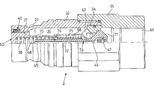
Fig. 3 is the longitdinal cross-section diagram that two elements of pipe fitting are coupled mutually.
Pipe fitting shown in the accompanying drawing is made up of recessed 1 and male member 2.
Recessed 1 as shown in Figure 2, rigidly fix between including mutually with the bottom: one has and is used to connect the feed nut 3 of internal thread of end or using end of fluid, the outer tube body 4 that the one end is made up of described nut 3, the interior tube body 6 of stationary annular chassis 5 that is installed with a plurality of openings 8 that pass through for fluids and one and outer tube body 4 concentric settings.Perfect anti-leakage between described outer tube body 4 and the described nut 3 is guaranteed by seal ring 7.
Stationary annular chassis 5 accommodates a fixing inside axial axis 9.In the outside of described axle 9, be provided with a leakproof sleeve pipe 10 that can have outstanding element 11 in axial sliding with one heart with it, stay so that an inner space 61 to be arranged; When inoperative, pipe fitting is opened, and promotes sleeve pipe 64 by a spring 12 described leakproof sleeve pipe 10 is pressed to the right vertically; Be complementary by bellend 13, described spring 12 applied forces be balanced, and sleeve pipe 10 maintained the state of a balance with axle 9.
The bellend 13 of sleeve pipe 10 and axle 9 is complementary and can prevents fluid flowing when off working state.
In outer tube body 4 inside, in leakproof sleeve pipe 10 outsides, be placed with the cleaning unit of a sleeve pipe that has end cross element 51 of being formed by sleeve pipe 15 itself with one heart, it can endwisely slip at the outer surface of interior tube body 6 and be compressed by retaining spring 16.
Seat 17 wherein is to be used for the interior tube body 6 that outstanding element 11 with leakproof sleeve pipe 10 is complementary a contact surface is arranged, and the latter has an additional seal ring 19 and the anti-device 20 that squeezes.
Outer tube body 4 is coupled in its end and male member 2, and the sliding shaft sleeve 30 with a retaining spring 60 is provided.Axle sleeve 30 is having an elastic ring 43 near inside, place, its rear end.
At the front end of internal surface, axle sleeve 30 provides an annular groove 41 at as shown in Figure 1 off-position and corresponding to the sequence of positions in the hole 42 of interior tube body 4, is used to limit the position separately of bead 23, to reach male member 2 and recessed 1 purpose of pinning.
The end surface of arranging outer tube body 30, axle sleeve 15, interior tube body 4 and axle 9 is labeled as 28 to form the plane of an integral body.
The male member 2 of pipe fitting comprises a fixing outer tube body 32 as shown in Figure 1, and outer tube body 32 is provided with one and has the end nut 35 that is used for the interior pipe 65 of feed end or using end coupling.In body 32, fixing by nut 35, be provided with an element 34 that is installed with a plurality of holes 67.Inner member 34 has the anterior external part 68 of a tubulose, has constituted an inside axial cavity 36 that its front end is closed by a piston 37 that is compressed by spring 38 jointly with outer tube body 32.Leakproof between outer tube body 32 and the piston 37 is guaranteed by one in the annular seating that is placed on body 32 seal ring of being made up of an elastic ring and O-shape ring 40.Described annular seating is near the front end of the interior tube body 32 that faces toward sleeve pipe 10.By seal ring 40 and piston 37 are complementary, the front end of axial cavity 36 can be closed.Piston 37 has a back cavity 70, and the mode that the tubulose external part of itself and inner member 34 slides vertically is complementary.
Also have a head 71 and be the safety valve 73 of mushroom shaped in male member 2, safety valve 73 has an axle 72, firmly is fixed with an annular buttress 76 that can slide for the breech 70 of piston above it thereon.The position of the head 71 relative interior tube bodies 34 of safety valve 73 keeps by a spring 75 usually, to block the passage between pipe 65 and the chamber 36.Spring 75 is inserted between the annular buttress 76 and radial wall 77 of interior tube body 34.Force in spring 38 on the piston and also be engaged in the annular buttress 76 of axle 72.
Insert an axial bolt 45 in axle 72 slidably, it stretches certain scope forward from axle 72, and the back leans against on the ball 46, and this ball 46 is compacted to a position with the pathway closure between the chamber 48 in described pipe 65 and the piston 37 by a spring 47.
In the back of seal ring 40, outer tube 32 has an annular seating 21, is used for recessed 1 ball 23 being held wherein during at coupling position when element 1 and 2.
The end surface of arranging outer tube body 32 and piston 37 is labeled as 50 to form the plane of an integral body.
According to the present invention, as depicted in figs. 1 and 2, be positioned at off working state from two concave, convex spares 1 and 2 of pipe fitting, realize that coupling is by element 1 and 2 is close, surface 28 and 50 is separately contacted.Especially, make the surface of perpendicular elements 51 of the surface of piston 37 and axle sleeve 15 contact with the surface of the outer tube body 32 of male member 2.
The step of first coupling is, under the driving of the outer tube body 32 of male member 2, recessed 1 axle sleeve 15 is retreated, and under recessed 1 axle 9 driving, the piston 37 of male member 2 being retreated, the result is opened the passage between the axial cavity 36 of recessed inner space 61 and male member.
Then, retreating of piston 37 causes retreating of bolt 45, and ball 46 is retreated, and the passage between pipe 65 and the chamber 48 is opened.Link to each other with the high-pressure liquid end of feeding if manage 65, just can guarantee that the fluid of release of safety valve 73 is up so that continue the manual coupling of two elements of pipe fitting, otherwise, understand because of the axial high pressure that is applied and can't realize.
On the contrary, through such stress-relief process, two elements 1 and 2 further axially near making piston 37 cause retreating of safety valve 73, thereby the passage of feeding between end pipe 65 and the chamber 36 is opened, and it has been connected with recessed 1 inner space 61, thus be connected to recessed self using end and connect.
Finish and firm coupling is that the slip of the axle sleeve 30 by recessed realizes that this at first needs to make ball 23 axial displacements to take place to a position, make and realize described slip and enter in the annular seating 21 of male member.
Rearmost position after coupling is finished and locked as shown in Figure 3.
It should be noted that for the startup of opening the bolt 45 that ball valve 46 carries out by piston 37 decisions, this piston is removed bolt 45 when inoperative, just in time just collides with bolt 45 before the end of fallback procedures.What this means ball valve 46 opens and does not rely on the pressure valve of pipe in 65 of feeding.
Claims (2)
1. the pipe fitting that is coupled fast comprises one recessed (1) and a male member (2) that can be coupled mutually, and described element (1,2) is by fixing parts (4,9; 32) parts (10,15 and in axial sliding; 37) form, when inoperative, be in the position that a passage (61,36,65) that makes fluid is closed, when two elements (1,2) when the appropriate section coupling is realized being coupled, be displaced to the position that described passage (61,36,65) is opened; The fixed component (4 of described recessed (1), 9) comprise a valve element of being formed by the fixedly axial inner axle (9) of end expansion (13), and the described sliding parts (10 of recessed (1), 15) comprise a sleeve pipe that endwisely slips (10) with the setting of described axle external concentric, to determine that is formed a described fluid passage opening (61,36, the inner space of a part 65) (61), and be complementary by the bellend (13) of elastic pressure and described axle (9), to reach the purpose of the described inner space (61) of closed tightly fluid passage when not being coupled with male member (2); The described standing part (32) of male member (2) comprises a fixedly body (32), and it has a seal ring (40) that can cover with the described sleeve pipe (10) of recessed (1) when described coupling takes place; And the described sliding parts (37) of male member (2) comprises that one can be depressed into and the be complementary sliding piston (37) of position of described seal ring (40) by elastic pressure, with the described passage (61 of the formation of closed tightly male member (2), 36, the axial cavity (36) of an extention 65), and at two elements (1 that pipe fitting takes place, when 2) being coupled, after the described bellend (13) of its front end and axle (9) is complementary, open passage; Can feed with fluid at the described axial cavity (36) of male member (2) and male member (1) and to be provided with a safety valve (73) between the end that end links to each other, to pin described passage of feeding between end (65) and the described axial cavity (36), and drive by described piston (37), at the described axial cavity (36) of the inner space of opening recessed (1) (61) and male member (2) afterwards, substantially when finishing, described coupling opens described passage, it is characterized in that, described male member (2) comprises that also being located at described fluid for one feeds and have the pressure-relief valve (46) of an opening bolt (45) between end (65) and the pressure-releasing cavity (48), and this opening bolt (45) is just in time directly driven by described piston (37) before safety valve (73) is opened.
2. pipe fitting according to claim 1, it is characterized in that, described pressure-relief valve (46) is a ball valve, and described opening bolt (45) is an axial bolt, usually be separated with described piston (37), and forwardly start in described piston (37) displacement afterwards, by described piston (37) with the described axial cavity (36) of opening male member (2).
Applications Claiming Priority (2)
| Application Number | Priority Date | Filing Date | Title |
|---|---|---|---|
| ITMI96A002211 | 1996-10-25 | ||
| IT96MI002211A IT1286038B1 (en) | 1996-10-25 | 1996-10-25 | QUICK COUPLING FITTING FOR PIPES WITH SAFETY VALVE AND PRESSURE RELEASE VALVE |
Publications (2)
| Publication Number | Publication Date |
|---|---|
| CN1234103A CN1234103A (en) | 1999-11-03 |
| CN1075618C true CN1075618C (en) | 2001-11-28 |
Family
ID=11375090
Family Applications (1)
| Application Number | Title | Priority Date | Filing Date |
|---|---|---|---|
| CN97198970A Expired - Lifetime CN1075618C (en) | 1996-10-25 | 1997-10-17 | Quick coupling pipe fitting with safety valve and pressure relieve valve |
Country Status (16)
| Country | Link |
|---|---|
| US (1) | US6026857A (en) |
| EP (1) | EP0932791B1 (en) |
| JP (1) | JP3945588B2 (en) |
| KR (1) | KR100522754B1 (en) |
| CN (1) | CN1075618C (en) |
| AT (1) | ATE219227T1 (en) |
| BR (1) | BR9712432A (en) |
| CA (1) | CA2269875C (en) |
| DE (1) | DE69713361T2 (en) |
| DK (1) | DK0932791T3 (en) |
| ES (1) | ES2178022T3 (en) |
| IL (1) | IL129362A (en) |
| IT (1) | IT1286038B1 (en) |
| NO (1) | NO318538B1 (en) |
| PT (1) | PT932791E (en) |
| WO (1) | WO1998019097A1 (en) |
Families Citing this family (26)
| Publication number | Priority date | Publication date | Assignee | Title |
|---|---|---|---|---|
| JPH10329352A (en) * | 1997-06-04 | 1998-12-15 | Brother Ind Ltd | Recording electrode body |
| US6095190A (en) | 1998-11-17 | 2000-08-01 | Snap-Tite Technologies, Inc. | Coupling with female half having internal pressure relief |
| US6145539A (en) * | 1999-04-12 | 2000-11-14 | Snap-Tite Technologies, Inc. | Balanced coupling with pressure bleed |
| US6382251B1 (en) * | 2000-03-29 | 2002-05-07 | Snap-Tite Technologies, Inc. | Coupling with male half having internal pressure relief |
| US6776187B1 (en) | 2003-03-06 | 2004-08-17 | Parker-Hannifin Corporation | Quick coupling with pressure assist piston |
| US6830059B1 (en) | 2003-09-08 | 2004-12-14 | Snap-Tite Technologies, Inc. | Low spill farm coupling |
| ITMI20051521A1 (en) * | 2005-08-03 | 2007-02-04 | Stucchi Spa | FEMALE ELEMENT FOR QUICK COUPLING FITTING FOR PIPING |
| ITMI20051643A1 (en) * | 2005-09-07 | 2007-03-08 | Faster Spa | QUICK COUPLING WITH COMPENSATION OF THE COUPLING TOLERANCES |
| US7762279B2 (en) | 2005-11-05 | 2010-07-27 | Snap-Tite Technologies, Inc. | Threaded coupling with flow shutoff |
| US7575024B2 (en) * | 2005-11-05 | 2009-08-18 | Snap-Tite Technologies, Inc. | Threaded coupling with flow shutoff |
| WO2008071012A1 (en) * | 2006-12-13 | 2008-06-19 | Oscar Meier Ag | Quick connect coupling for connecting hydraulic lines, especially in earth moving machines and the interchangeable add-on devices and tools thereof |
| ITMI20091455A1 (en) | 2009-08-07 | 2011-02-08 | Stucchi Spa | QUICK RELEASE WITH FLOW DEVIATION DEVICE |
| IT1395157B1 (en) | 2009-08-07 | 2012-09-05 | Stucchi Spa | QUICK COUPLING WITH ANTI-LOCK SAFETY DEVICE |
| DE102010019094A1 (en) * | 2010-04-30 | 2011-11-03 | Rheinisch-Westfälische Technische Hochschule Aachen | Hydraulic coupling sleeve |
| EP2626612B1 (en) | 2012-02-08 | 2014-12-10 | Eaton SAS | Coupling device with residual pressure relief system |
| ITMI20130522A1 (en) * | 2013-04-05 | 2014-10-06 | Alfa Gomma S P A | HYDRAULIC OR HYDRAULIC QUICK COUPLING FOR FLUID IN PRESSURE |
| ITMI20131866A1 (en) * | 2013-11-11 | 2015-05-12 | Stucchi Spa | COUPLING WITH FLAT FACE FOR FLUID TRANSMISSION WITH ANULAR FRONT GASKET. |
| DE102014010570B4 (en) * | 2014-07-16 | 2023-10-12 | U.M. Gewerbeimmobilien Gmbh & Co. Kg | Coupling part for a coupling for pressure fluid lines |
| US9976659B2 (en) | 2015-06-01 | 2018-05-22 | Holmbury, Ltd. | Decompression coupling block |
| DE102015222639A1 (en) * | 2015-11-17 | 2017-05-18 | U.M. Gewerbeimmobilien Gmbh & Co. Kg | Clutch sleeve for a hydraulic clutch |
| US10156310B2 (en) | 2015-11-18 | 2018-12-18 | Parker-Hannifin Corporation | Non-spill connect under pressure coupler |
| FR3046209B1 (en) * | 2015-12-23 | 2018-02-16 | Staubli Faverges | RAPID CONNECTION FEMALE ELEMENT AND RAPID CONNECTION COMPRISING SUCH A FEMALE ELEMENT |
| US11040868B2 (en) * | 2016-05-19 | 2021-06-22 | Walnab Pty Ltd | Fluid coupling assembly |
| BR112019027274B1 (en) * | 2017-06-23 | 2022-02-15 | Frank's International, Llc | APPARATUS FOR CONNECTING A DISTAL END OF A FLUID CONDUIT TO A FLUID INLECTION AND METHOD FOR CONNECTING A DISTAL END OF A FLUID CONDUIT TO A FLUID INLECTION OF A CEMENTING OR FRACTURING TOOL |
| FR3080165B1 (en) | 2018-04-12 | 2020-05-01 | Staubli Faverges | FITTING ELEMENT AND FITTING COMPRISING SUCH A FITTING ELEMENT |
| US11262014B2 (en) * | 2020-06-10 | 2022-03-01 | Blue Origin, Llc | Quick disconnect coupling systems and related methods |
Citations (5)
| Publication number | Priority date | Publication date | Assignee | Title |
|---|---|---|---|---|
| GB2147074A (en) * | 1983-09-22 | 1985-05-01 | Ekman K R | Pipe coupling-pressure reduction device |
| DE4101001A1 (en) * | 1990-01-17 | 1991-07-18 | Dart Engineering Ag | CLUTCH PART DEVICE WITH PRESSURE REDUCING ELEMENTS |
| US5215122A (en) * | 1991-12-09 | 1993-06-01 | Aeroquip Corporation | Quick disconnect fluid coupling with integral pressure relief feature |
| GB2278420A (en) * | 1993-05-28 | 1994-11-30 | Dart Engineering Ag | Quick coupling pipe connector |
| EP0686800A1 (en) * | 1994-06-08 | 1995-12-13 | STUCCHI S.r.l. | Quick-coupling fitting for pipes, provided with a safety valve |
Family Cites Families (1)
| Publication number | Priority date | Publication date | Assignee | Title |
|---|---|---|---|---|
| US5918633A (en) * | 1997-02-10 | 1999-07-06 | Snap-Tite Technologies, Inc. | Farm coupling |
-
1996
- 1996-10-25 IT IT96MI002211A patent/IT1286038B1/en active IP Right Grant
-
1997
- 1997-10-17 EP EP97948809A patent/EP0932791B1/en not_active Expired - Lifetime
- 1997-10-17 ES ES97948809T patent/ES2178022T3/en not_active Expired - Lifetime
- 1997-10-17 PT PT97948809T patent/PT932791E/en unknown
- 1997-10-17 BR BR9712432-0A patent/BR9712432A/en not_active IP Right Cessation
- 1997-10-17 US US09/284,727 patent/US6026857A/en not_active Expired - Lifetime
- 1997-10-17 JP JP52003598A patent/JP3945588B2/en not_active Expired - Lifetime
- 1997-10-17 AT AT97948809T patent/ATE219227T1/en active
- 1997-10-17 KR KR10-1999-7003624A patent/KR100522754B1/en not_active IP Right Cessation
- 1997-10-17 IL IL12936297A patent/IL129362A/en not_active IP Right Cessation
- 1997-10-17 CN CN97198970A patent/CN1075618C/en not_active Expired - Lifetime
- 1997-10-17 CA CA002269875A patent/CA2269875C/en not_active Expired - Lifetime
- 1997-10-17 DE DE69713361T patent/DE69713361T2/en not_active Expired - Lifetime
- 1997-10-17 WO PCT/EP1997/005913 patent/WO1998019097A1/en active IP Right Grant
- 1997-10-17 DK DK97948809T patent/DK0932791T3/en active
-
1999
- 1999-04-23 NO NO19991958A patent/NO318538B1/en not_active IP Right Cessation
Patent Citations (5)
| Publication number | Priority date | Publication date | Assignee | Title |
|---|---|---|---|---|
| GB2147074A (en) * | 1983-09-22 | 1985-05-01 | Ekman K R | Pipe coupling-pressure reduction device |
| DE4101001A1 (en) * | 1990-01-17 | 1991-07-18 | Dart Engineering Ag | CLUTCH PART DEVICE WITH PRESSURE REDUCING ELEMENTS |
| US5215122A (en) * | 1991-12-09 | 1993-06-01 | Aeroquip Corporation | Quick disconnect fluid coupling with integral pressure relief feature |
| GB2278420A (en) * | 1993-05-28 | 1994-11-30 | Dart Engineering Ag | Quick coupling pipe connector |
| EP0686800A1 (en) * | 1994-06-08 | 1995-12-13 | STUCCHI S.r.l. | Quick-coupling fitting for pipes, provided with a safety valve |
Also Published As
| Publication number | Publication date |
|---|---|
| IL129362A0 (en) | 2000-02-17 |
| AU728363B2 (en) | 2001-01-11 |
| ES2178022T3 (en) | 2002-12-16 |
| IL129362A (en) | 2003-12-10 |
| JP2001502784A (en) | 2001-02-27 |
| NO318538B1 (en) | 2005-04-11 |
| AU6910198A (en) | 1998-05-22 |
| NO991958D0 (en) | 1999-04-23 |
| EP0932791B1 (en) | 2002-06-12 |
| DE69713361T2 (en) | 2002-11-21 |
| CN1234103A (en) | 1999-11-03 |
| CA2269875A1 (en) | 1998-05-07 |
| US6026857A (en) | 2000-02-22 |
| PT932791E (en) | 2002-11-29 |
| ITMI962211A1 (en) | 1998-04-25 |
| EP0932791A1 (en) | 1999-08-04 |
| DK0932791T3 (en) | 2002-09-16 |
| KR100522754B1 (en) | 2005-10-19 |
| ATE219227T1 (en) | 2002-06-15 |
| CA2269875C (en) | 2007-12-18 |
| KR20000052805A (en) | 2000-08-25 |
| NO991958L (en) | 1999-06-25 |
| JP3945588B2 (en) | 2007-07-18 |
| BR9712432A (en) | 1999-10-26 |
| DE69713361D1 (en) | 2002-07-18 |
| WO1998019097A1 (en) | 1998-05-07 |
| IT1286038B1 (en) | 1998-07-07 |
Similar Documents
| Publication | Publication Date | Title |
|---|---|---|
| CN1075618C (en) | Quick coupling pipe fitting with safety valve and pressure relieve valve | |
| TWI439343B (en) | Clamping device | |
| KR102591218B1 (en) | In-port sequence valve | |
| US4598896A (en) | Quick disconnect coupling | |
| EP0340879B1 (en) | Pressure-sealed plug coupling | |
| EP1750907B1 (en) | Handheld hydraulic assembly tool | |
| US8033524B2 (en) | Female connector element and connector incorporating such an element | |
| US4221235A (en) | Quick disconnect coupling | |
| KR102300778B1 (en) | Fluid pressure cylinder with booster mechanism | |
| US4664148A (en) | Quick disconnect coupling with a lockable valve actuator | |
| JPH0854089A (en) | Pipe quick connector with safety valve | |
| GB2087019A (en) | Quick-action conduit coupling | |
| JP2000515953A (en) | Quick connection type coupling | |
| US5950679A (en) | High pressure plug coupling | |
| EP2452778A1 (en) | Clamp device | |
| EP0681139B1 (en) | Device for plugging the interior of a pipe | |
| JP2002502481A (en) | Quick coupling fitting | |
| JP3359973B2 (en) | Quick fitting | |
| US20050230651A1 (en) | Protection of a seal element | |
| JPH09505383A (en) | Pipe connector | |
| CN1795343A (en) | Fast coupling unit with integrated check valve | |
| US20040211474A1 (en) | Pipe coupling | |
| EP0316080B1 (en) | Connect-against-pressure coupling | |
| US5725034A (en) | Pressurized fluid dispensing nozzle | |
| JP4348589B2 (en) | Connector with safety release device |
Legal Events
| Date | Code | Title | Description |
|---|---|---|---|
| C06 | Publication | ||
| PB01 | Publication | ||
| C10 | Entry into substantive examination | ||
| SE01 | Entry into force of request for substantive examination | ||
| C14 | Grant of patent or utility model | ||
| GR01 | Patent grant | ||
| CX01 | Expiry of patent term | ||
| CX01 | Expiry of patent term |
Granted publication date: 20011128 |