CN107533119B - Shim coil for magnetic resonance imaging - Google Patents
Shim coil for magnetic resonance imaging Download PDFInfo
- Publication number
- CN107533119B CN107533119B CN201580078692.4A CN201580078692A CN107533119B CN 107533119 B CN107533119 B CN 107533119B CN 201580078692 A CN201580078692 A CN 201580078692A CN 107533119 B CN107533119 B CN 107533119B
- Authority
- CN
- China
- Prior art keywords
- shim coils
- subset
- shim
- coils
- region
- Prior art date
- Legal status (The legal status is an assumption and is not a legal conclusion. Google has not performed a legal analysis and makes no representation as to the accuracy of the status listed.)
- Active
Links
Images


Classifications
-
- G—PHYSICS
- G01—MEASURING; TESTING
- G01R—MEASURING ELECTRIC VARIABLES; MEASURING MAGNETIC VARIABLES
- G01R33/00—Arrangements or instruments for measuring magnetic variables
- G01R33/20—Arrangements or instruments for measuring magnetic variables involving magnetic resonance
- G01R33/28—Details of apparatus provided for in groups G01R33/44 - G01R33/64
- G01R33/38—Systems for generation, homogenisation or stabilisation of the main or gradient magnetic field
- G01R33/387—Compensation of inhomogeneities
- G01R33/3875—Compensation of inhomogeneities using correction coil assemblies, e.g. active shimming
-
- G—PHYSICS
- G01—MEASURING; TESTING
- G01R—MEASURING ELECTRIC VARIABLES; MEASURING MAGNETIC VARIABLES
- G01R33/00—Arrangements or instruments for measuring magnetic variables
- G01R33/20—Arrangements or instruments for measuring magnetic variables involving magnetic resonance
- G01R33/28—Details of apparatus provided for in groups G01R33/44 - G01R33/64
- G01R33/38—Systems for generation, homogenisation or stabilisation of the main or gradient magnetic field
- G01R33/385—Systems for generation, homogenisation or stabilisation of the main or gradient magnetic field using gradient magnetic field coils
-
- G—PHYSICS
- G01—MEASURING; TESTING
- G01R—MEASURING ELECTRIC VARIABLES; MEASURING MAGNETIC VARIABLES
- G01R33/00—Arrangements or instruments for measuring magnetic variables
- G01R33/20—Arrangements or instruments for measuring magnetic variables involving magnetic resonance
- G01R33/44—Arrangements or instruments for measuring magnetic variables involving magnetic resonance using nuclear magnetic resonance [NMR]
- G01R33/48—NMR imaging systems
- G01R33/54—Signal processing systems, e.g. using pulse sequences ; Generation or control of pulse sequences; Operator console
- G01R33/543—Control of the operation of the MR system, e.g. setting of acquisition parameters prior to or during MR data acquisition, dynamic shimming, use of one or more scout images for scan plane prescription
Landscapes
- Physics & Mathematics (AREA)
- Condensed Matter Physics & Semiconductors (AREA)
- General Physics & Mathematics (AREA)
- Engineering & Computer Science (AREA)
- Signal Processing (AREA)
- High Energy & Nuclear Physics (AREA)
- Magnetic Resonance Imaging Apparatus (AREA)
Abstract
The present invention provides a method for operating a Magnetic Resonance Imaging (MRI) system, comprising: multiplexing data indicative of a first substrate for imaging a portion of the subject disposed in a main magnet of the MRI system to generate a magnetic field; selecting a first subset of shim coils from a set of available shim coils arranged and configured to provide improved magnetic field homogeneity at the first substrate when the shim coils in the first subset are driven; and driving the shim coils of the selected first subset of shim coils without driving other shim coils of the set of available shim coils such that the first base magnetic field is more uniform than the first base magnetic field when the selected first subset of shim coils is not driven.
Description
Background of the invention:
this disclosure relates to magnetic resonance imaging.
The invention content is as follows:
in one aspect, an embodiment provides a method for operating a Magnetic Resonance Imaging (MRI) system, comprising: multiplexing data indicative of a first substrate for imaging a portion of the subject disposed in a main magnet of the MRI system to generate a substantially uniform magnetic field; selecting, based on the retrieved data, a first subset of shim coils from a set of available shim coils and by means of a control unit associated with the MRI system, the first subset being arranged and configured such that the homogeneity of the magnetic field at the first substrate is improved when the shim coils in the first subset are driven; and driving the shim coils of the selected first subset of shim coils without driving other shim coils of the set of available shim coils to provide a first base magnetic field having a higher homogeneity than a first base magnetic field when the selected first subset of shim coils is not driven.
Implementations may include one or more of the following features. The method may further comprise: respective weights are determined by the control unit to apply to the shim coils in the selected first set of shim coils. Driving the shimming coils in the selected first subset of shimming coils may further comprise: generating currents on the shim coils in each selected first subset of shim coils that are proportional to the respective weights of the shim coils in the selected first subset; and distributing the generated currents to the shim coils in the selected first subset.
Driving the shim coils in the selected first subset of shim coils may include simultaneously driving the shim coils in the selected first subset of shim coils. Driving the shim coils in the selected first subset of shim coils may include: a set of power amplifiers is connected to the selected first subset of shim coils, wherein the number of power amplifiers is less than the number of shim coils in the set of available shim coils. Connecting the power amplifier group may include: the power amplifiers are connected to the selected first subset of shim coils such that the power amplifier in each power amplifier group is connectable to a respective one of the shim coils in the selected first subset of shim coils. Connecting the power amplifier bank may include connecting the power amplifier bank to the selected first subset of shim coils such that each power amplifier in the power amplifier bank is connected to more than one respective shim coil.
The method may further comprise retrieving data indicative of a second substrate used to capture an image of another portion of the subject, the second substrate being different from the first substrate; selecting a second subset of shim coils arranged and configured in a manner such that when the shim coils in the second subset are driven, the homogeneity of the magnetic field at the second volume is also improved, based on data retrieved from the second volume indicated by a control unit associated with the MRI system and from a set of available shim coils, the second volume differing from the first volume by at least one shim coil; and driving the shim coils in the second subset of shim coils without driving the shim coils in the other set of available shim coils such that the homogeneity of the magnetic field at the second substrate is higher than the homogeneity of the magnetic field at the second substrate when the selected second subset of shim coils is not driven.
Driving the selected first subset of shim coils may include connecting a set of power amplifiers into the selected first subset of shim coils, wherein a number of power amplifiers in the set is less than a number of shim coils in the set of available shim coils; and driving the shim coils in the selected second subset of shim coils may comprise: disconnecting the power amplifier bank from the selected first subset of shim coils; and connecting the power amplifier bank to the selected second subset of shim coils after disconnecting the power amplifier bank from the selected first subset of shim coils.
In another aspect, an embodiment provides a Magnetic Resonance Imaging (MRI) system, comprising: a housing having a cavity and an imaging body disposed in the cavity; a main magnet contained within said housing and disposed within the bore to generate a substantially uniform magnetic field; placing a set of available shim coils around the housing and configured to increase the homogeneity of the magnetic field; a pulse generating coil to generate and apply Radio Frequency (RF) pulses to scan a subject; the gradient coils perturbing the substantially uniform magnetic field to encode MRI signals obtained in response to the applied RF pulses; a control unit and coupled to the main magnet and configured to: retrieving data indicative of a first substrate used to capture an image of at least a portion of the subject; based on the retrieved data, selecting a first subset of shim coils from a set of available shim coils, the first subset of shim coils being arranged and configured in a manner such that when the first subset of shim coils is driven there, the homogeneity of the magnetic field at the first substrate is also improved; and causing the shim coils in the selected first subset of shim coils to be driven without driving the shim coils in the other set of available shim coils such that the first base magnetic field is more uniform than the first base magnetic field when the selected first subset of shim coils is not driven.
Implementations may include one or more of the following features. The control unit is further configured to: respective weights are determined, which are applied to the shimming coils in this selected first subset of shimming coils. The MRI system may further include: a set of power amplifiers, wherein the number of power amplifiers is less than the number of shim coils in the set of available shim coils. Each power amplifier may be configured to: the shim coils in each selected first subset of shim coils generate currents according to the determined respective weights. Each power amplifier may be connected to a respective shim coil. Each power amplifier may be connected to more than one shim coil. Each shim coil may be configured to: the magnetic field is field corrected according to a particular order basis function. Wherein the specific power basis function may be a spherical harmonic function.
The control unit may be further configured to: retrieving second substrate data indicative of an image of the portion of the body disposed in the cavity; selecting, from a set of available shim coils, a second subset of shim coils arranged and configured in a manner such that homogeneity of the magnetic field is also improved at the second basis when the first subset of shim coils is driven, based on the reconstructed data indicative of the selected second basis, the selected second subset being different from the first subset by at least one shim coil; and causing the shim coils in the selected second subset of shim coils to be driven without driving the shim coils in the other available set of shim coils such that the first base magnetic field is more uniform than the second base magnetic field when the selected second subset of shim coils is not driven.
The control unit may be further configured to: causing the shimming coils in the selected first subset of shimming coils to be driven comprises: connecting a power amplifier bank to the selected first subset of shim coils; and causing the driving of the shim coils in the selected second subset of shim coils to comprise: disconnecting the group of power amplifiers from the selected first subset of power amplifiers; and connecting the power amplifier bank to the selected second shim coil subset after the power amplifier bank is disconnected from the selected first shim coil subset.
A single or multiple aspects of the subject matter described in this specification is illustrated in the figures and description that follows. Other features, aspects, and advantages of the subject matter will become apparent from the description, the drawings, and the claims.
Drawings
Embodiments will now be described, by way of example, with reference to the accompanying drawings, in which:
figure 1 shows an example of a Magnetic Resonance Imaging (MRI) system in which shim coils are provided from a solenoid magnet.
Fig. 2A shows a 3D image of an example of a 16-channel shim coil array.
Fig. 2B shows a side view of an example of a 16-channel shim coil array.
Fig. 2C shows an example of using a subset of a 16-channel shim coil array.
Fig. 3A-3C illustrate various aspects of an example of a process for operating shim coils.
Like reference symbols in the various drawings indicate like elements.
DETAILED DESCRIPTION OF EMBODIMENT (S) OF INVENTION
Various embodiments and aspects of the disclosure are described below with reference to the detailed discussion. The following description and drawings are illustrative of the disclosure and are not to be construed as limiting the disclosure. A thorough understanding of various embodiments of the present disclosure is provided in describing numerous specific details. However, in order to provide a brief discussion of the disclosed embodiments, common or customary details may not be set forth in some instances.
The present disclosure provides, in accordance with selected embodiments, a magnetic resonance imaging system and apparatus in which an array of shim coils are located within, for example, a solenoid magnet sidewall. In certain instances, to achieve improved magnetic field uniformity for a particular substrate of interest, a subset of shim coils may be selected such that a set of power amplifiers may be dedicated to driving the selected subset of shim coils. In the latter example, a different subset is also selected from available shim coils, but this different subset is also driven from the same set of power amplifiers as described above to improve the magnetic field homogeneity at another different volume of interest. The power per power amplifier may be weighted differently when driving a particular subset of shim coils to achieve improved goals for field uniformity. This weight variation is related to, for example, the size of the selected subset of shim coils and the particular selected basis.
This shimming effect can be tailored specifically to improve field uniformity within a particular substrate of interest, from dynamically selecting power amplifier groups and connecting shim coils as needed. This approach can significantly improve the use of all available shim coils to increase field uniformity in a particular area of interest. This approach may result in a reduction in the number of power amplifiers used for the uniform field, and thus a reduction in hardware costs, by reusing the same power amplifier in different subsets of shim coils.
Fig. 1A-1B illustrate perspective and cross-sectional views of an example Magnetic Resonance Imaging (MRI) system 100 in which a solenoidal magnet 105 is configured in the shape of a cylinder with an internal bore 101. A coil assembly 107, which includes the transmit coil 106 and the gradient coil 104, is disposed within the solenoidal magnet 105. Generally, coil assembly 107 may be formed as an annular structure and received within an inner bore of solenoid magnet 105. In certain embodiments, the loop coil assembly 107 includes only the gradient coils 104. In this embodiment, the loop coil assembly does not include the transmit coil 106 or any receiver coil. For these implementations, Radio Frequency (RF) signals are transmitted by, for example, a local coil for imaging of the head 102 of the photographic patient 103. In one case, a head coil configured in a birdcage shape is used to transmit and receive RF signals for imaging the subject. In another case, one curved coil transmits RF signals to the subject and one phased array coil is configured to receive responsive MR signals. In another case, curved coils are used to transmit RF signals to the subject, and phased array coils are configured to respond to received MR signals. Embodiments provided herein may be applicable to intraoperative MRI and MRI systems for emergency room settings.
In certain embodiments, the shim coils 109 are housed within the cylindrical wall of the solenoid magnet 105. A set of power amplifiers provides power to the shim coils 109. For example, power amplifiers 110A and 110B housed in the control room may be connected to the shim coils 109 to provide shimming for the magnetic field in the inner bore 101. In driving the shim coils 109, the power amplifiers 110A and 110B may be controlled by a control unit 111. The control unit 111 typically includes one or more processors and programming logic for configuring the power amplifiers 110A and 110B. In some cases, the control unit 111 is housed in a control room separate from the solenoid magnet 105 of the MRI system 100. In this embodiment, an array of shim coils may be used to provide adjustment of the field strength within the inner bore 101 so that the magnetic field within the inner bore 101 becomes more uniform, as described in more detail below.
Fig. 2A shows a 3D image of an example of a 16-channel shim coil array 200. In this configuration, the 16 shim coils are distributed over a spherical surface, and the selection of the distribution positions results in an improved homogeneity in all three spatial dimensions. Fig. 2B shows a side view of the 16-channel shim coil array 200. The side view shows only 8 of the 16 shim coils on the viewing side. The side view shows only 8 of the 16 shim coils on the viewing side. That is, these eight coils are annotated as coils 202A to 202H. Each shim coil may be driven by a power amplifier having a particular current. Generally, each shim coil may provide shimming, which is defined by a spatial harmonic function (e.g., spherical harmonic) of a particular order. From the spatial symmetry of the spatial harmonic function, one of the 16 shim coils can be driven with the same current in some cases in order to adjust the specific matrix enclosed by the sphere.
Fig. 2C shows an example of using a subset of the 16-channel shim coil array 200 to exclusively adjust one particular volume of interest 210 for activation. As shown, the focus matrix 210 is here within the range shown in gray. A subset of the 16-channel shim coil array 200 may be used to adjust the magnetic field within the matrix 210, i.e., as shown by shim coils 202C, 202D, 202G, and 202H, which are shown in bold in fig. 2C. In other words, the shim coils 202C, 202D, 202G, and 202H are dynamically connected to the power amplifier when selected. This subset of shim coils selects the unselected shim coils, i.e., coils 202A, 202B, 202E, and 202F, as inactive coils. When the coils 202A, 202B, 202E, 202F are not selected during the adjustment process, they are not connected to a power amplifier. This selection method allows the shimming protocol to focus on using a subset of shim coils. In some cases, the subset of shim coils may be selected from their distance from the substrate of interest in which the magnetic field is to be adjusted. In other cases, a subset of such shim coils may be selected according to a corresponding spatial harmonic function that may be generated in order to adjust the magnetic field in the target volume of interest. For example, the adjustment of the magnetic field may be achieved from a selection of four most significant order spatial harmonics, and these four spatial harmonics may correspond to four particular shim coils. When the four spatial harmonics are combined with corresponding weights, the shimming effects of the four spatial harmonics may be mixed. The corresponding weights for the spatial harmonics may be determined such that the combination produces a target shimming effect at the ROI (i.e., the volume of Interest or "Region of Interest"). It is noted that a spherical arrangement of shim coils is one implementation. In other embodiments, the shim coils may be shaped and arranged on a cylindrical curved surface, such as the curved surface of the cylindrical structure of the solenoid magnet 105. This arrangement may be referred to as a cylindrical configuration. Although the above illustration provides an example of using shim coils 202C, 202D, 202G, and 202H to increase field uniformity within the volume 210, field uniformity within different volumes may be increased using different subsets of shim coils. The following discussion describes further details of the shimming procedure.
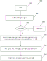
Fig. 3A-3C illustrate a flow diagram of example aspects for operating shim coils 300 of an MRI system 100. When the process flow is initiated (302), data (304) indicative of a substrate of interest (ROI) within the magnetic field may be retrieved. In one example, data indicative of the volume of interest may be stored, for example, in a data memory of one of the control units 111, which is associated with the MRI system 100, and this stored data may be retrieved at the time of the shimming procedure. The coordinates of the substrate of interest may also be determined from the operator's selection of a particular substrate of interest, for example, based on a scout scan of the patient's head 102 in the internal cavity 101. The selected substrate of interest may be converted into physical coordinates within the inner bore 101 by the control unit 111 of the MRI system 100.
Next, the control unit 111 determines whether there is a need for adjustment (306). In some cases, this determination may be made based on operator input from the MRI system 100. Other examples may include an automatic shimming aspect. To quantify the baseline quality of field uniformity, the spectral width, for example, from the Free Induced Decay (FID) of the substrate of interest (i.e., "freeness decay") may be measured in certain embodiments. So that the spectral width of the FID signal is sufficiently narrow for the targeted imaging application, the imaging procedure may proceed without shimming (308). Otherwise, a shimming procedure may be performed, as discussed in more detail below.
When shimming is required, the controller 111 selects a first subset of shim coils from the set of available shim coils based on the retrieved data. The first subset of shim coils is arranged and configured in a manner such that when the shim coils are driven in the first subset, the homogeneity of the magnetic field at the first substrate is also uniformly improved. For example, in the example of substrate of interest selection described above, the internal cavities 101 are based on the selected substrate of interest (ROI). May be determined from the control unit 111 of the MRI system 100, and this position coordinate corresponds to the selected ROI. This position coordinate allows the control unit to select a first subset of shim coils from the available shim coils to adjust the magnetic field in the selected ROI (310). As described above, this selected shim coil may then be driven by the power amplifier (without driving the other shim coils) to produce a correction field such that the field uniformity within the selected ROI is higher than the field uniformity within the selected ROI when the uniformity-enhancing coil within the selected shim coil is not driven (312).
In an embodiment, the specific weight applied at the shim coil may be determined from a selected subset of shim coils (314). In this embodiment, the current may then be generated from a power amplifier on each shim coil (316) in the selected subset of shim coils. The current generated is proportional to the determined weight of each leveling coil. Thereafter, the power amplifier may distribute the generated currents to each shim coil (318).
In a certain embodiment, driving each selected shim coil in the subset of shim coils includes dynamically connecting a set of power amplifiers to the selected subset of shim coils (320). In some configurations, each power amplifier in the set of power amplifiers is connected to a respective selected shim coil in the subset of shim coils (322). In other configurations, each power amplifier in the power amplifier group is connected to more than one respective shim coil (324). In these configurations, the number of power amplifiers may be less than the number of available shim coils. Thus, a subset of the available shim coils may be dynamically connected as needed at a particular shimming procedure. In this particular shimming procedure, this subset of shim coils dynamically connected to the power amplifier may be driven simultaneously. In this subset of shim coils, the shim coils are driven, while the shim coils in the available set of shim coils, except for the subset, are not driven, so that the magnetic field in the body of interest is more homogeneous.
In certain implementations, the data indicative of new and different matrices of interest may also be retrieved, resulting in the shimming procedure being performed in a new magnetic field, which corresponds to the position coordinates in the inner bore 101. In one example, data indicative of this new volume of interest may be stored, for example, in a data memory of one of the control units 111, which is associated with the MRI system 100, and this stored data may be retrieved at the time of the shimming procedure. The coordinates of this new substrate of interest may also be determined from the operator's selection of a particular substrate of interest, for example, based on a scout scan of the patient's head 102 in the internal cavity 101. This newly selected substrate of interest may be converted into physical coordinates within the inner bore 101 by the control unit 111 of the MRI system 100. This new shimming procedure can be performed from new and different subsets of shim coils using the same power amplifier. This subset of new shim coils may be more suitable than the previous subset for achieving shimming in the new volume of interest. In more detail, driving the new shim coil subset includes disconnecting the set of power amplifiers from the previous shim coil subset and then connecting the same set of power amplifiers to the new shim coil subset. By reusing the same power amplifier, the power amplifier hardware can be used with different shim coils, which are particularly useful for particular substrates of interest.
As used herein, the terms "comprises" and "comprising" are to be interpreted as inclusive and open-ended, and not exclusive. In particular, the terms "comprises" and "comprising," as well as variations thereof, when used in this specification and claims, mean inclusion of the specified features, steps, or components. The terms are not to be interpreted to exclude the presence of other features, steps or components.
As used herein, the term "exemplary" means "serving as an example, instance, or illustration," and should not be construed as preferred or advantageous over other configurations disclosed herein.
As used herein, the terms "about" and "approximately" are meant to include variations that may exist in the upper and lower limits of value ranges, such as variations in characteristics, parameters, and dimensions. In one non-limiting example, the terms "about" and "approximately" mean ± 10% or less.
The specific embodiments described above have been shown by way of example, and it should be understood that these embodiments may be susceptible to various modifications and alternative forms. It should be further understood that the claims are not intended to be limited to the particular forms disclosed, but rather to cover all modifications, equivalents, and alternatives falling within the spirit and scope of this disclosure.
Claims (25)
1. A method for operating a magnetic resonance imaging system, comprising:
accessing data indicative of a first region for imaging at least a portion of a subject, the portion being disposed within a main magnet of an MRI system and the main magnet producing a substantially uniform magnetic field;
selecting, by a control unit associated with the MRI system and from a set of available shim coils, a first subset of shim coils based on the accessed data, the first subset of shim coils being arranged and configured such that homogeneity of the magnetic field over the first region is improved when the shim coils in the first subset of shim coils are driven; and
dynamically connecting a set of power amplifiers to shim coils in the selected first subset of shim coils, while non-selected shim coils are not connected to power amplifiers, thereby driving the shim coils in the selected first subset of shim coils and not driving other shim coils in the set of available shim coils, such that homogeneity of the magnetic field at the first region is improved over homogeneity of the magnetic field at the first region when the shim coils in the selected first subset of shim coils are not driven.
2. A method for operating a magnetic resonance imaging system as claimed in claim 1, wherein the set of available shim coils are arranged in a spherically curved surface.
3. A method for operating a magnetic resonance imaging system as claimed in claim 1, wherein the set of available shim coils are arranged in a cylindrically curved surface.
4. The method of claim 1, further comprising:
determining, by a control unit, respective weights to apply to the shim coils in the selected first subset of shim coils.
5. The method of claim 4, wherein the control unit determines respective weights according to the size of the selected subset of shim coils and the selected first region.
6. The method of claim 4, wherein driving the shim coils in the selected first subset of shim coils comprises:
generating a current on each shim coil in the selected first subset of shim coils, wherein the current of each shim coil in the selected first subset of shim coils is proportional to the respective weight of the shim coil; and
distributing the generated current to each shim coil in the selected first subset of shim coils.
7. The method of claim 1, wherein driving shim coils in the selected first subset of shim coils comprises simultaneously driving the shim coils in the selected first subset of shim coils.
8. The method of claim 1, wherein the number of power amplifiers in the set of power amplifiers is less than the number of shim coils in the set of available shim coils.
9. The method of claim 8, wherein connecting the set of power amplifiers comprises:
connecting the set of power amplifiers to the selected first subset of shim coils such that each power amplifier in the set of power amplifiers is connected to a respective one of the shim coils in the selected first subset of shim coils.
10. The method of claim 8, wherein connecting the set of power amplifiers comprises:
connecting the set of power amplifiers to the selected first subset of shim coils such that each power amplifier in the set of power amplifiers is connected to more than one respective shim coil.
11. The method of claim 1, further comprising:
accessing data indicative of a second region for imaging another portion of the subject, the second region being different from the first region;
selecting, by a control unit associated with the MRI system and from a set of available shim coils, a second subset of shim coils arranged and configured such that when shim coils in the second subset of shim coils are driven, homogeneity of the magnetic field over the second region is improved, the second subset of shim coils differing from the first subset of shim coils by at least one shim coil, based on the access data indicative of the second region; and
disconnecting the set of power amplifiers from the shim coils in the selected first subset of shim coils; and
after the set of power amplifiers is disconnected from the shim coils in the selected first subset of shim coils, the set of power amplifiers is connected to the selected second subset of shim coils, thereby driving the shim coils in the second subset of shim coils without driving other shim coils in the set of available shim coils such that the uniformity of the magnetic field over the second region is improved over the uniformity of the magnetic field over the second region when the shim coils in the selected second subset of shim coils are not driven.
12. The method of claim 11, wherein:
the number of power amplifiers in the set of power amplifiers is less than the number of shim coils in the set of available shim coils.
13. A magnetic resonance imaging system, comprising:
a housing having a cavity and an imaging body disposed in the cavity;
a main magnet contained within said housing and disposed within the bore to generate a substantially uniform magnetic field;
placing a set of available shim coils around the housing and configured to increase the homogeneity of the magnetic field;
a pulse generating coil for sequentially generating radio frequency pulses and applying the radio frequency pulses to scan the subject;
a gradient coil perturbing the substantially uniform magnetic field to encode magnetic resonance imaging signals acquired in response to the applied radio frequency pulses;
a control unit and coupled to the main magnet and configured to:
accessing data indicative of a first region for imaging at least a portion of a subject;
selecting, based on the accessed data, a first subset of shim coils from the set of available shim coils, the first subset of shim coils being arranged and configured such that when shim coils in this first subset of shim coils are driven, homogeneity of the magnetic field over the first region is improved; and
dynamically connecting a set of power amplifiers to the selected first subset of shim coils without unselected shim coils being connected to a power amplifier, thereby causing shim coils in the selected first subset of shim coils to be driven without driving other shim coils in the set of available shim coils such that homogeneity of the magnetic field in the first region is improved over homogeneity of the magnetic field in the first region when the selected first subset of shim coils is not driven.
14. The magnetic resonance imaging system of claim 13, wherein the control unit is further configured to:
determining respective weights, the weights applied to the shimming coils in the selected first subset of shimming coils.
15. The magnetic resonance imaging system of claim 14, wherein:
the number of power amplifiers in the set of power amplifiers is less than the number of shim coils in the set of available shim coils.
16. The magnetic resonance imaging system of claim 15, wherein each power amplifier is configured to:
generating a current on each shim coil in the selected first subset of shim coils according to the determined respective weight.
17. The magnetic resonance imaging system of claim 15, wherein each power amplifier is connected to a respective shim coil.
18. The magnetic resonance imaging system of claim 15, wherein each power amplifier is connected to more than one shim coil.
19. The magnetic resonance imaging system of claim 14, wherein each shim coil is configured to:
the magnetic field is field corrected according to a particular order basis function.
20. The magnetic resonance imaging system of claim 19, wherein the particular order basis function is a spherical harmonic.
21. The magnetic resonance imaging system of claim 14, wherein the selected first subset of shim coils corresponds to a set of basis functions, and wherein more than first order basis functions are mixed according to their respective determined weights.
22. The magnetic resonance imaging system of claim 13, wherein the control unit is further configured to:
accessing data indicative of a second region for imaging a portion of a subject placed in a hole;
selecting, based on the access data indicative of the second region, a second subset of shim coils from the set of available shim coils, the second subset of shim coils being arranged and configured such that homogeneity of the magnetic field over the second region is improved when the shim coils in the selected second subset of shim coils are driven, the selected second subset of shim coils being different from the first subset of shim coils by at least one shim coil; and
disconnecting the set of power amplifiers from the shim coils in the selected first subset of shim coils; and
connecting the set of power amplifiers to the selected second subset of shimming coils after the set of power amplifiers is disconnected from the shimming coils in the selected first subset of shimming coils, thereby causing each shimming coil in the selected second subset of shimming coils to be driven without driving the other shimming coils in the set of available shimming coils such that the homogeneity of the magnetic field in the second region is improved over the homogeneity of the magnetic field in the second region when the shimming coils in the selected second subset of shimming coils are not driven.
23. The magnetic resonance imaging system of claim 13, wherein the set of available shim coils are arranged in a spherically curved surface.
24. The magnetic resonance imaging system of claim 13, wherein the set of available shim coils are arranged in a cylindrically curved surface.
25. The magnetic resonance imaging system of claim 14, wherein the control unit determines the respective weights according to the size of the selected subset of shim coils and the selected first region.
Applications Claiming Priority (1)
| Application Number | Priority Date | Filing Date | Title |
|---|---|---|---|
| PCT/IB2015/052628 WO2016162734A1 (en) | 2015-04-10 | 2015-04-10 | Shimming coils for magnetic resonance imaging |
Publications (2)
| Publication Number | Publication Date |
|---|---|
| CN107533119A CN107533119A (en) | 2018-01-02 |
| CN107533119B true CN107533119B (en) | 2020-07-28 |
Family
ID=57072043
Family Applications (1)
| Application Number | Title | Priority Date | Filing Date |
|---|---|---|---|
| CN201580078692.4A Active CN107533119B (en) | 2015-04-10 | 2015-04-10 | Shim coil for magnetic resonance imaging |
Country Status (7)
| Country | Link |
|---|---|
| US (2) | US10551454B2 (en) |
| JP (1) | JP6647314B2 (en) |
| CN (1) | CN107533119B (en) |
| CA (1) | CA2981658C (en) |
| DE (1) | DE112015006439T5 (en) |
| GB (1) | GB2553465B (en) |
| WO (1) | WO2016162734A1 (en) |
Families Citing this family (2)
| Publication number | Priority date | Publication date | Assignee | Title |
|---|---|---|---|---|
| DE112015006439T5 (en) | 2015-04-10 | 2017-12-28 | Synaptive Medical (Barbados) Inc. | Shim coils for magnetic resonance imaging |
| CN116087849B (en) * | 2023-02-28 | 2023-11-17 | 江苏力磁医疗设备有限公司 | Gradient coil special for MRI |
Citations (7)
| Publication number | Priority date | Publication date | Assignee | Title |
|---|---|---|---|---|
| JPH0295288A (en) * | 1988-09-30 | 1990-04-06 | Shimadzu Corp | Automatic magnetic field shimming device |
| EP0982598B1 (en) * | 1998-08-28 | 2007-07-11 | Koninklijke Philips Electronics N.V. | Magnetic resonance system with shim rings |
| CN101612042A (en) * | 2008-06-26 | 2009-12-30 | 株式会社东芝 | MR imaging apparatus and MR imaging method |
| CN101903790A (en) * | 2007-12-21 | 2010-12-01 | 皇家飞利浦电子股份有限公司 | Passive shims to increase the effective B0 and B1 uniformity in a body coil |
| CN102356330A (en) * | 2009-03-20 | 2012-02-15 | 皇家飞利浦电子股份有限公司 | A tesseral shim coil for a magnetic resonance system |
| CN102879753A (en) * | 2012-10-11 | 2013-01-16 | 中国科学院近代物理研究所 | Automatic implementation method for high-uniformity magnet shim coil design |
| CN103654783A (en) * | 2012-09-05 | 2014-03-26 | 三星电子株式会社 | Magnetic resonance imaging (MRI) apparatus and manufacturing method thereof |
Family Cites Families (26)
| Publication number | Priority date | Publication date | Assignee | Title |
|---|---|---|---|---|
| US5760582A (en) * | 1992-07-23 | 1998-06-02 | Fonar Corporation | Optimized gradient coils and shim coils for magnetic resonance scanning systems |
| US6023167A (en) | 1998-01-26 | 2000-02-08 | Picker International, Inc. | Surface coils with integrated shims |
| US6507190B1 (en) * | 2000-08-01 | 2003-01-14 | Ge Medical Systems Global Technologies Company Llc | Method and apparatus for compensating polarizing fields in magnetic resonance imaging |
| DE10114319C2 (en) * | 2001-03-23 | 2003-02-13 | Siemens Ag | Shim device for a magnetic resonance device |
| US20050154291A1 (en) * | 2003-09-19 | 2005-07-14 | Lei Zhao | Method of using a small MRI scanner |
| WO2005091012A1 (en) * | 2004-03-17 | 2005-09-29 | Koninklijke Philips Electronics N.V. | Dynamic shimset calibration for b0 offset |
| US7224167B2 (en) * | 2004-11-30 | 2007-05-29 | General Electric Company | Magnetic field generating apparatus and method for magnetic resonance imaging |
| WO2006097864A1 (en) * | 2005-03-17 | 2006-09-21 | Koninklijke Philips Electronics, N.V. | Minimum energy shim coils for magnetic resonance |
| EP1808707A1 (en) | 2006-01-16 | 2007-07-18 | Kabushiki Kaisha Toshiba | Magnetic resonance imaging apparatus and static magnetic field correction method |
| US7592812B2 (en) * | 2006-04-13 | 2009-09-22 | Kabushiki Kaisha Toshiba | Magnetic resonance imaging apparatus and static magnetic field correction method |
| GB2442750B (en) | 2006-10-10 | 2010-09-15 | Siemens Magnet Technology Ltd | Shimming of Magnet Systems |
| GB2448479B (en) | 2007-04-18 | 2009-06-03 | Siemens Magnet Technology Ltd | Improved shim for imaging magnets |
| EP2329283A1 (en) | 2008-09-17 | 2011-06-08 | Koninklijke Philips Electronics N.V. | Rf shimming with rf power regularization using a multi-channel rf transmit system for mri |
| CN101995560B (en) * | 2009-08-31 | 2013-11-06 | 西门子(深圳)磁共振有限公司 | Method and device for compensating insufficient magnetic field uniformity |
| JP5603642B2 (en) | 2010-04-27 | 2014-10-08 | 株式会社日立メディコ | Magnetic resonance imaging apparatus and shimming method |
| US9500731B2 (en) | 2010-10-15 | 2016-11-22 | Eleazar Castillo | Shimming device and method to improve magnetic field homogeneity in magnetic resonance imaging devices |
| US8981778B2 (en) * | 2011-04-26 | 2015-03-17 | General Electric Company | Method and apparatus for imaging a patient using local shim coils |
| DE102011077724A1 (en) | 2011-06-17 | 2012-12-20 | Siemens Aktiengesellschaft | Local shim coil within a local coil, as local BO homogenization in an MRI |
| EP2734855B1 (en) | 2011-07-20 | 2021-06-30 | Koninklijke Philips N.V. | Wireless local transmit coils and array with controllable load |
| DE102011080275B4 (en) | 2011-08-02 | 2018-10-25 | Siemens Healthcare Gmbh | Local coil, in particular neck coil, with a number of separately switchable local coil shim coils |
| DE102011086658B3 (en) | 2011-11-18 | 2013-03-28 | Siemens Aktiengesellschaft | Shim coil device for use in local coil of magnetic resonance apparatus, has shim coil and compensation coil arranged in coil plane, where overall assembly of shim coil and compensation coil is symmetrical with respect to two central axes |
| US8981779B2 (en) * | 2011-12-13 | 2015-03-17 | Viewray Incorporated | Active resistive shimming fro MRI devices |
| BR112014015024A2 (en) | 2011-12-23 | 2017-06-13 | Koninklijke Philips Nv | rm device |
| JP6071905B2 (en) | 2012-01-11 | 2017-02-01 | 株式会社日立製作所 | Magnetic resonance imaging apparatus and area imaging method |
| DE102015204955B4 (en) | 2015-03-19 | 2019-05-16 | Siemens Healthcare Gmbh | Method for magnetic resonance imaging |
| DE112015006439T5 (en) | 2015-04-10 | 2017-12-28 | Synaptive Medical (Barbados) Inc. | Shim coils for magnetic resonance imaging |
-
2015
- 2015-04-10 DE DE112015006439.7T patent/DE112015006439T5/en active Pending
- 2015-04-10 CN CN201580078692.4A patent/CN107533119B/en active Active
- 2015-04-10 WO PCT/IB2015/052628 patent/WO2016162734A1/en active Application Filing
- 2015-04-10 US US15/546,393 patent/US10551454B2/en active Active
- 2015-04-10 GB GB1717753.6A patent/GB2553465B/en active Active
- 2015-04-10 JP JP2017552976A patent/JP6647314B2/en active Active
- 2015-04-10 CA CA2981658A patent/CA2981658C/en active Active
-
2020
- 2020-01-27 US US16/773,532 patent/US11237235B2/en active Active
Patent Citations (7)
| Publication number | Priority date | Publication date | Assignee | Title |
|---|---|---|---|---|
| JPH0295288A (en) * | 1988-09-30 | 1990-04-06 | Shimadzu Corp | Automatic magnetic field shimming device |
| EP0982598B1 (en) * | 1998-08-28 | 2007-07-11 | Koninklijke Philips Electronics N.V. | Magnetic resonance system with shim rings |
| CN101903790A (en) * | 2007-12-21 | 2010-12-01 | 皇家飞利浦电子股份有限公司 | Passive shims to increase the effective B0 and B1 uniformity in a body coil |
| CN101612042A (en) * | 2008-06-26 | 2009-12-30 | 株式会社东芝 | MR imaging apparatus and MR imaging method |
| CN102356330A (en) * | 2009-03-20 | 2012-02-15 | 皇家飞利浦电子股份有限公司 | A tesseral shim coil for a magnetic resonance system |
| CN103654783A (en) * | 2012-09-05 | 2014-03-26 | 三星电子株式会社 | Magnetic resonance imaging (MRI) apparatus and manufacturing method thereof |
| CN102879753A (en) * | 2012-10-11 | 2013-01-16 | 中国科学院近代物理研究所 | Automatic implementation method for high-uniformity magnet shim coil design |
Non-Patent Citations (1)
| Title |
|---|
| 永磁型磁共振系统中匀场线圈设计的研究;董薛;《中国优秀硕士学位论文全文数据库 基础科学辑》;20111115;第A005-50页 * |
Also Published As
| Publication number | Publication date |
|---|---|
| US10551454B2 (en) | 2020-02-04 |
| GB2553465A (en) | 2018-03-07 |
| WO2016162734A1 (en) | 2016-10-13 |
| US11237235B2 (en) | 2022-02-01 |
| CA2981658A1 (en) | 2016-10-13 |
| DE112015006439T5 (en) | 2017-12-28 |
| US20180024212A1 (en) | 2018-01-25 |
| CA2981658C (en) | 2021-02-09 |
| JP2018510730A (en) | 2018-04-19 |
| JP6647314B2 (en) | 2020-02-14 |
| GB2553465B (en) | 2021-06-09 |
| US20200400765A1 (en) | 2020-12-24 |
| CN107533119A (en) | 2018-01-02 |
| GB201717753D0 (en) | 2017-12-13 |
Similar Documents
| Publication | Publication Date | Title |
|---|---|---|
| US20160091587A1 (en) | Medical imaging apparatus having multiple subsystems, and operating method therefor | |
| US11650273B2 (en) | Adaptive shim coils for MR imaging | |
| CN110353681A (en) | By high-frequency signal to the corrected method and apparatus of B0 inhomogeneities | |
| US20140028314A1 (en) | Method and apparatus for acquisition of magnetic resonance data while avoiding signal inhomogeneities | |
| US10732243B2 (en) | Method and apparatus for optimization of a time progression of a magnetic resonance control sequence | |
| CN107533119B (en) | Shim coil for magnetic resonance imaging | |
| US11275140B2 (en) | Emulation mode for MRI | |
| US11194000B2 (en) | Active b1+ shimming of transmission coils | |
| US10509089B2 (en) | Method and magnetic resonance apparatus to acquire trace-weighted magnetic resonance data with anisotropic diffusion directions | |
| US10042022B2 (en) | Method for magnetic resonance imaging and magnetic resonance device | |
| CN112345987A (en) | Active coil for shifting a homogeneous magnetic field space | |
| JP2014236868A (en) | Magnetic resonance imaging apparatus and method for adjusting uniformity of high-frequency magnetic field | |
| US20200225304A1 (en) | Method and device for controlling a magnetic resonance tomography system for magnetic resonance fingerprinting measurements | |
| US11754651B2 (en) | Patient-model-based determination of a stimulation of a magnetic resonance imaging | |
| US10459050B2 (en) | Magnetic resonance method and apparatus for reducing the repetition time without increasing the gradient capacity utilization | |
| JP2018510730A5 (en) | ||
| US10459054B2 (en) | Method and apparatus for implementing a diffusion-weighted magnetic resonance measurement | |
| US11686799B2 (en) | Method and apparatus for generation of combined magnetic resonance images | |
| EP3550320A1 (en) | Mimicking magnetic resonance imaging characteristics using post-processing | |
| JPWO2020225268A5 (en) |
Legal Events
| Date | Code | Title | Description |
|---|---|---|---|
| PB01 | Publication | ||
| PB01 | Publication | ||
| SE01 | Entry into force of request for substantive examination | ||
| SE01 | Entry into force of request for substantive examination | ||
| GR01 | Patent grant | ||
| GR01 | Patent grant | ||
| TR01 | Transfer of patent right |
Effective date of registration: 20210106 Address after: Toronto, Ontario, Canada Patentee after: SANAP medical Co. Address before: Bridgeton, Barbados Patentee before: SYNAPTIVE MEDICAL (BARBADOS) Inc. |
|
| TR01 | Transfer of patent right |