CN107532846B - Household appliance device - Google Patents
Household appliance device Download PDFInfo
- Publication number
- CN107532846B CN107532846B CN201680022168.XA CN201680022168A CN107532846B CN 107532846 B CN107532846 B CN 107532846B CN 201680022168 A CN201680022168 A CN 201680022168A CN 107532846 B CN107532846 B CN 107532846B
- Authority
- CN
- China
- Prior art keywords
- container
- frame
- household appliance
- appliance device
- partially
- Prior art date
- Legal status (The legal status is an assumption and is not a legal conclusion. Google has not performed a legal analysis and makes no representation as to the accuracy of the status listed.)
- Active
Links
Images


Classifications
-
- F—MECHANICAL ENGINEERING; LIGHTING; HEATING; WEAPONS; BLASTING
- F25—REFRIGERATION OR COOLING; COMBINED HEATING AND REFRIGERATION SYSTEMS; HEAT PUMP SYSTEMS; MANUFACTURE OR STORAGE OF ICE; LIQUEFACTION SOLIDIFICATION OF GASES
- F25D—REFRIGERATORS; COLD ROOMS; ICE-BOXES; COOLING OR FREEZING APPARATUS NOT OTHERWISE PROVIDED FOR
- F25D25/00—Charging, supporting, and discharging the articles to be cooled
- F25D25/02—Charging, supporting, and discharging the articles to be cooled by shelves
- F25D25/024—Slidable shelves
- F25D25/025—Drawers
-
- F—MECHANICAL ENGINEERING; LIGHTING; HEATING; WEAPONS; BLASTING
- F25—REFRIGERATION OR COOLING; COMBINED HEATING AND REFRIGERATION SYSTEMS; HEAT PUMP SYSTEMS; MANUFACTURE OR STORAGE OF ICE; LIQUEFACTION SOLIDIFICATION OF GASES
- F25D—REFRIGERATORS; COLD ROOMS; ICE-BOXES; COOLING OR FREEZING APPARATUS NOT OTHERWISE PROVIDED FOR
- F25D27/00—Lighting arrangements
-
- F—MECHANICAL ENGINEERING; LIGHTING; HEATING; WEAPONS; BLASTING
- F25—REFRIGERATION OR COOLING; COMBINED HEATING AND REFRIGERATION SYSTEMS; HEAT PUMP SYSTEMS; MANUFACTURE OR STORAGE OF ICE; LIQUEFACTION SOLIDIFICATION OF GASES
- F25D—REFRIGERATORS; COLD ROOMS; ICE-BOXES; COOLING OR FREEZING APPARATUS NOT OTHERWISE PROVIDED FOR
- F25D2317/00—Details or arrangements for circulating cooling fluids; Details or arrangements for circulating gas, e.g. air, within refrigerated spaces, not provided for in other groups of this subclass
- F25D2317/04—Treating air flowing to refrigeration compartments
- F25D2317/041—Treating air flowing to refrigeration compartments by purification
- F25D2317/0413—Treating air flowing to refrigeration compartments by purification by humidification
- F25D2317/04131—Control means therefor
Abstract
In order to improve versatility, a household appliance device, in particular a household refrigeration appliance device, is proposed, comprising: an inner container (10a) defining a storage space (12 a); a container (14a) arranged within the storage space (12 a); a manual actuator (16 a; 16 d; 16 f; 16g) configured for adjusting the humidity inside the container (14 a); a receiving member (20a-20f) at least partially housing a manual actuator (16 a; 16 d; 16 f; 16 g); and a frame (22 a; 22 b; 22 d; 22f) arranged within the storage space (12a), the receiving members (20a-20f) being fixed to the frame.
Description
Technical Field
The invention relates to a domestic appliance device, in particular a domestic refrigeration appliance device.
Background
US 2007/104841 a1 discloses a household appliance, in particular a household refrigeration appliance, such as a refrigerator, comprising a liner defining a storage space and a shelf which is non-detachably fixed to the liner and divides the storage space into at least two storage regions. The household appliance further comprises a container arranged below the shelf in one of the storage areas. Furthermore, the household appliance comprises a lighting device arranged at the bottom of the shelf for illuminating the interior space of the container.
Disclosure of Invention
It is an object of the invention, inter alia, to provide a household appliance device with improved properties in terms of versatility.
A household appliance device, in particular a household refrigeration appliance device, is proposed herein, comprising: a liner defining a storage space; a container disposed within the storage space; a manual actuator configured to adjust humidity within the container; a receiver to at least partially receive a manual actuator; and a frame arranged within the storage space, the receiver advantageously being fixed to the frame.
The household appliance device may particularly further comprise a lighting unit configured for illuminating the interior space of the container, wherein preferably the receptacle at least partially accommodates said lighting unit. The household appliance can in particular also comprise an insert which can be inserted into the storage space, preferably with a receiving recess, and in particular can also comprise a separate at least one fixing unit with a fixing element which is configured for detachably fixing the insert to the liner, wherein the fixing unit is advantageously arranged at least largely within the receiving recess. Furthermore, the manual actuator may particularly comprise a control element, the manual actuator preferably defining at least one lock-in position for the control element, said lock-in position particularly corresponding to at least one humidity level within the container.
By means of the invention, the versatility of the household appliance device can be improved. Furthermore, since the receiving member protects the additional unit of the home appliance device received in the receiving member, the durability of the home appliance device can be improved. In addition, the service, maintenance and repair work of the household appliance device can be simplified, in particular due to the advantageous arrangement of the manual actuation member and preferably the lighting unit. Furthermore, the operation of the household appliance device may be improved, in particular by enhancing the preservation of the food stored in the container. In addition, the visibility of food stored within the container may be enhanced.
In this context, "construction" especially means specifically designed and/or equipped. An object is configured for a specific function, in particular to be understood as an object which, in at least one application state and/or operating state, carries out and/or carries out the specific function. A "household appliance device" is to be understood to mean, in particular, at least one part, preferably a sub-assembly group, of a household appliance. The household appliance is particularly provided for storing and preferably tempering food, for example beverages, meat, fish, vegetables, fruits, milk and/or dairy products, in at least one operating state, advantageously for the purpose of enhancing the preservability of the stored food. However, the household appliance may also be embodied as a household appliance for heating, in particular for cooking, food, for example an oven, a food steamer and/or a microwave oven. Advantageously, the domestic appliance is embodied as a domestic refrigeration appliance which, in at least one operating state, is configured for cooling food. The domestic refrigeration appliance can be embodied in particular as a climate cabinet, an ice bin, a refrigerator, a freezer, a combined refrigerator-freezer and/or wine cabinet.
The storage space is in particular a space for storing food within the household appliance device. The storage space may particularly at least partially be divided into at least two storage areas, preferably a plurality of storage areas. In the mounted state of the household appliance device, the container is in particular movably arranged within the storage space, in particular within at least one of the storage regions, advantageously beneath an insert, a frame, a receptacle, a closure plate, a shelf and/or a cover of the household appliance device. The container is particularly configured to be arrangeable at least partially in the storage space in at least two positions, namely a first position and a second position. The first position is in particular a storage position, wherein the container is preferably configured for storing food, and the second position is in particular a use position, wherein the container is preferably configured for receiving food. The container is embodied in particular as a drawer.
In this context, a "manual actuator" is to be understood in particular as a unit configured for receiving a manual input and preferably for adjusting the humidity inside the container advantageously at least on the basis of the manual input. The manual input is in particular provided via a control element. In order to regulate the humidity, the manual actuator may in particular regulate at least one further physical parameter of the container which is related to the humidity, such as pressure, temperature and/or air flow. The receiving part comprises in particular at least one housing, in particular a receiving shell, which is configured to at least partially, preferably at least largely, advantageously completely, receive at least one further unit of the domestic appliance device, in particular a manual actuator and/or a lighting unit. The term "at least predominantly" in relation to the object especially means more than 50%, preferably more than 70%, advantageously more than 90% of the volume, especially the enclosed volume and/or mass of the object.
The lighting unit particularly comprises a lighting device comprising light, for example LEDs, OLEDs and/or a display. In particular in the mounted state of the domestic appliance arrangement, the lighting unit, in particular the lighting arrangement, is preferably arranged at least partially, preferably largely, advantageously completely, on the bottom of the receiving element and advantageously faces the container. The lighting device is especially arranged such that the main illumination direction of the lighting device and the main scale plane of the receiving element form an angle between 0 ° and 90 °, preferably between 0 ° and 45 °. A "major-dimension plane" of an object is to be understood in particular as a plane which extends parallel to the largest side of an imaginary rectangular cuboid which surrounds the object exactly completely and preferably extends through the geometric center of the object.
In this context, a "frame" is to be understood in particular as a separate unit which at least partially surrounds at least one further unit, in particular a receiving element, of the household appliance device in at least one viewing direction, preferably in a direction perpendicular to a main dimension plane of the frame. In this context, "separate" means in particular that it is separate from any other unit of the household appliance device and preferably not implemented integrally with any other unit of the household appliance device. "integrally implemented" in this context means in particular at least being connected by means of substance-substance bonding, for example by means of a welding process, adhesive bonding, injection molding process and/or by means of other processes which are considered advantageous by a person skilled in the art. Advantageously, "integrally implemented" may particularly denote being made of one piece. By "made of one piece" is meant herein, in particular, made of a single piece, for example by being made of a single cast piece and/or by being made in a single-component or multicomponent injection molding process, advantageously from a single blank.
In this context, a "receiving recess" is to be understood to mean, in particular, a recess which is at least partially, preferably largely, advantageously completely, surrounded on at least three sides, in particular on at least four sides, and which is designed for at least partially, preferably largely, advantageously completely, receiving a fastening unit. The insert can be embodied in particular as a shelf configured for storing food, a bottle holder and/or a partition which preferably divides the storage space into at least two storage areas in the mounted state of the domestic appliance device. The insert is preferably configured for regulating humidity within the container. Furthermore, the insert advantageously comprises at least one, advantageously a plurality of substructures of the domestic appliance device, such as a receptacle, a manual actuator, a lighting unit, a frame, a cover for the container and/or a closure plate. In this context, "detachable" is to be understood in particular as being detachable non-destructively and preferably tool-free.
The locked-in position corresponds in particular to a preferably factory-set default humidity level.
Furthermore, it is proposed herein that the receiving member is detachably fixed to the frame. In the mounted state of the household appliance, the receiving element is in particular configured to be removable from the frame at least by sliding the receiving element along the frame, preferably at least substantially parallel to the main dimension direction of the frame and/or the receiving element. The "main dimension direction" of an object is to be understood in this context in particular as a direction which runs parallel to the largest side of an imaginary rectangular cuboid which surrounds the object only exactly completely. "at least substantially parallel" is to be understood in particular as meaning the following orientation of a direction, in particular in a plane, relative to a reference direction: wherein the deviation of the direction from the reference direction is in particular less than 15 °, advantageously less than 10 °, in particular advantageously less than 2 °. Thus, disassembly can be simplified. In particular, service, maintenance and repair work on the household appliance device, preferably on the receiving member and/or on the units accommodated therein, can advantageously be carried out simply.
In order to fix the receiving element to the frame, it is proposed that the receiving element comprises a deformable latching element and a holding element, which has a higher rigidity than the latching element, the latching element and the holding element being configured for fixing the receiving element to the frame. In this context, "deformable" means in particular elastically deformable, preferably reversibly deformable, advantageously reversibly deformable repeatedly. In this context, an object having a higher stiffness than another object is to be understood in particular that the objects differ in their deformability, preferably due to design and/or material properties, such as e.g. modulus of elasticity. Advantageously, the latching element is at least partially deformable in a direction at least substantially perpendicular to the direction of the major dimension of the receiving element and/or the frame. Alternatively or additionally, the catch element may be at least partially deformable in a direction at least substantially parallel to the main dimension plane of the frame and/or the receiving element. The term "at least substantially perpendicular" is intended in particular to define herein an orientation of a direction relative to a reference direction, wherein, viewed in particular in one plane, the direction and the reference direction enclose an angle of between 80 ° and 100 °, in particular between 85 ° and 95 °, preferably between 88 ° and 92 °, particularly advantageously 90 °. Thus, the receiving member can be connected to the frame in a simple manner. In particular, the assembly of the household appliance device can be further simplified.
The latching element and/or the retaining element can be arranged in particular at an outer wall of the receptacle for fixing the receptacle to the frame. In order to avoid additional components and tools for fastening the receiving element and to reduce costs, it is proposed that the receiving element comprises an outer wall which at least partially, preferably at least largely, advantageously completely, forms the latching element. The latching element is in particular embodied integrally with the outer wall. The latching element comprises in particular a snap hook and a preferably deformable snap arm connected to the snap hook, wherein the snap arm is advantageously embodied integrally at least partially by an outer wall. In particular adjacent to the latching element, the outer wall is embodied at least partially separately from the base plate of the receiving element. Furthermore, the holding element can be embodied, in particular, at least partially by the outer wall. The retaining element may in particular comprise a wedge-shaped insert element and in particular a recess.
It is also proposed herein that the receiver comprises an opening on at least one side through which the manual actuator extends at least partially. The opening extends in particular at least partially, preferably largely, advantageously completely on one side, in particular such that the receiving element is at least partially, in particular at least largely, advantageously completely open on the at least one side. In the mounted state of the household appliance device, the partially open side is an upper side of the receiving element, in particular an upper side opposite to the floor of the receiving element. Furthermore, in the installed state of the domestic appliance device, the partially open side faces the closing plate. The receiving member is in particular tray-shaped. Preferably, the outer wall of the receiving member is arranged on the base plate and has a height at least substantially greater than the thickness of the base plate. "at least substantially greater than" is intended to mean at least 50% greater, preferably at least 100% greater, advantageously at least 150% greater. In this way, the assembly and arrangement of the manual actuator and/or the lighting unit within the receiving element may be simplified.
Furthermore, it is proposed herein that the receiving element, in particular the floor panel of the receiving element, comprises at least one through recess on at least one other side, in particular arranged opposite to the partially open side, in which the manual actuator, in particular the control element, is at least partially accommodated. Advantageously, the other side comprises an opening for a lighting device. Thus, the manual actuator may be connected to a further component arranged below the receiving member.
In a preferred embodiment of the invention, the household appliance device further comprises a closing plate configured for at least partially closing the at least partially open side of the receptacle. The closing plate is embodied in particular as a shelf configured for storing food. Thus, the receptacle may be sealed against moisture, in particular condensed water and/or spilled liquid, for preventing water from damaging a unit, in particular a manual actuator and/or a lighting unit, received by the receptacle.
In order to enable a user to easily control the manual actuator from above the receptacle, the closure plate comprises a receiving recess configured for at least partially receiving a movable control element of the manual actuator, in particular the aforementioned control element.
Furthermore, it is proposed herein that the control element, in particular a surface of the control element, is at least substantially flush with at least one surface of the closing plate. In this context, "at least substantially flush" is to be understood in particular to mean that the difference in height between two objects is less than 2mm, preferably less than 0.5mm, advantageously less than 0.13 mm. Thereby, it is avoided that food, e.g. beverages, is placed on top of the control element without safety, which may lead to water being spilled into the receptacle. Furthermore, damage to the control element can be avoided.
Furthermore, it is proposed herein that the receptacle comprises a protective inner barrier configured for at least substantially preventing moisture from entering the lighting unit. The protective inner barrier is particularly arranged within the receptacle and preferably distinguished from the outer wall area. The inner barrier extends in particular at least partially from the floor of the receptacle to the closing plate. This makes it possible to prevent moisture from damaging the lighting unit.
In a particularly preferred embodiment of the invention, the receiving member comprises at least two compartments, a first compartment at least partially housing the lighting unit and a second compartment at least partially housing the manual actuator, wherein the two compartments are at least partially separated by a protective inner barrier. Thus, the humidity sensitive electronic components of the lighting unit may be protected and in particular may be separated from the manual actuator.
Advantageously, the protective inner barrier comprises a drain channel configured for collecting condensed water. The inner barrier comprises in particular at least two side walls at least partially defining the discharge channel, namely a first side wall delimiting the first compartment and a second side wall facing away from the second compartment. In particular, the drain channel comprises a slope configured for guiding the condensed water away from the lighting unit. The inner barrier further particularly comprises a drain connected to the drain channel and configured for conveying the condensate away from the receiver. Thus, condensed water can be collected and can in particular be transported away from the electrical component.
For adjusting the humidity, the manual actuator can be configured for adjusting a temperature adjustment device, a fan and/or a valve of the container. Advantageously, the container has an opening, wherein the manual actuator is configured for adjusting the opening degree of the opening for adjusting the humidity inside the container. In this context, "degree of opening" is to be understood in particular as the proportion of the open surface of the opening that is not covered. In particular, a manual actuator is communicatively connected to the lid of the container opening and is configured for adjusting the movement of the lid relative to the container opening. Thus, the air flow between the interior of the container and the exterior of the container, in particular the storage space, is used to easily adjust the humidity.
It is also proposed herein that the frame comprises a fixing recess at least partially shaped to correspond to the snap-lock element, the frame further comprising a retaining recess at least partially shaped to correspond to the retaining element. The retaining recess receives the retaining element, in particular during assembly, preferably in an assembly step, when the frame and the receiver are moved towards each other, preferably at least substantially perpendicular to each other. In particular during assembly, preferably in a further assembly step, the fixing recess captures the catch element when the frame and the receiver are moved alongside one another, preferably at least substantially parallel to one another. In the assembled state, the fixing recess is particularly configured for locking the snap hook of the catch element in place. In particular, the fastening recess releases the catch element when the catch element is pushed towards the receiving element, preferably in a removal step. In particular, upon disassembly, preferably in a further disassembly step, the retaining recess releases the retaining element when the frame and the receiver are moved alongside one another, preferably at least substantially parallel to one another. Thus, assembly and/or disassembly may be simplified.
In a preferred embodiment of the invention, the retaining recess has an insert part configured for receiving the retaining element, in particular the insert element, and a retaining part for fixing the retaining element, in particular the recess, in a form-fitting manner. Thus, assembly and/or disassembly may be further simplified.
Advantageously, it is proposed herein that the frame is detachably fixed to the liner. Therefore, the assembly and disassembly can be further simplified, and the repair work of the receiving member can be easily performed.
In another aspect of the invention, in particular for the purpose of configuring the household appliance device with different quality characteristics, a first module of the household appliance device is proposed, which comprises: a manual actuator configured for adjusting humidity within the container; and a receiver that at least partially houses the manual actuator and is securable to the frame. The first module preferably does not have any kind of lighting unit, which is preferably configured for illuminating the interior space of the container. In particular, herein, a second module of a household appliance device is proposed, comprising: a manual actuator configured to adjust humidity inside the container; a lighting unit configured to illuminate an interior space of the container; and a receiving element at least partially housing the lighting unit, at least partially housing the manual actuator, and securable to the frame.
Based on the corresponding selection of the first module or the second module, the household appliance device can be equipped with different quality features, for example a manual actuator and/or a lighting unit. In order to achieve a home appliance device with different quality characteristics, in a further aspect of the invention a construction kit for constructing a home appliance device is proposed, the construction kit comprising: a frame; a first module and a second module. Furthermore, the construction kit may in particular comprise at least two, preferably a plurality of first modules and/or in particular at least two, preferably a plurality of second modules. Therefore, the versatility of the home appliance can be improved.
In order to manufacture household appliance devices having different quality characteristics, in an additional aspect of the invention, a method for manufacturing a household appliance device, in particular with a construction kit, is proposed, the method comprising the steps of: providing a frame; providing a first module; providing a second module; and securing the first module or the second module to the frame. In particular, a method for manufacturing a set of household appliance devices, in particular with a construction kit, is proposed herein, comprising the following steps: providing a set of frames; providing a set of first modules; providing a set of second modules; and securing at least one first module of the set of first modules or at least one second module of the set of second modules to at least one frame of the set of frames.
It is also proposed herein that the fixing element is configured for fixing the insert to the liner when the insert is pushed into the storage space, preferably at least partially, at least largely, advantageously completely, in the pushing-in direction of the insert. In this context, "insertion direction" is to be understood to mean, in particular, a direction which, in the installed state of the domestic appliance device, is at least substantially parallel to a horizontal plane of the domestic appliance device and points toward the rear side of the interior. Advantageously, in the fixing position of the insert, the fixing element blocks any movement of the insert at least in the pull-out direction and/or in the push-in direction. In this context, the term "pull-out direction" is to be understood in particular to mean a direction which, in the installed state of the household appliance device, is at least substantially parallel to the horizontal plane of the household appliance device and faces away from the rear side of the interior. The insert can thus be fixed to the liner in a simple manner.
In order to advantageously fix the insert to the frame, the fixing element is at least substantially hook-shaped. An object is in particular "at least substantially hook-shaped" if it comprises at least a head arranged obliquely with respect to the main dimension direction of the object. In particular, the fixing element comprises a head which is inclined with respect to the main dimension direction of the fixing element, wherein preferably the obtuse angle between the head of the fixing element and the main dimension direction is at least 270 ° and/or at most 360 °.
Furthermore, it is proposed herein that the accommodation recess comprises a receiving opening configured for receiving the fixation unit when assembled. The receiving recess comprises in particular a receiving opening on a side of the side wall facing the inner container in the mounted state of the household appliance device. Thus, the fixing unit can be arranged in the accommodating recess in a simple manner.
Furthermore, it is proposed herein that the receiving recess comprises a through-opening through which the fixing element passes when fixing the insert to the inner container. The receiving recess comprises in particular a through opening on a side facing the bottom wall or the top wall of the inner container in the mounted state of the household appliance device. The receiving opening is in particular at least substantially larger than the through opening. The insert can thus be mechanically fixed to the liner in a simple manner.
In one embodiment of the invention, it is proposed herein that the receiving opening and the through opening are connected. Thus, the fixing unit can be arranged even more easily within the accommodation recess.
In order to separate the assembly of the fixing unit and the fixing function of the fixing unit, the receiving opening and the through opening have opening directions which are at least substantially perpendicular to each other.
It is also proposed herein that the insert comprises an assembly element located within the receiving recess, said assembly element being configured at least for connecting the fixing unit to the insert. The assembly element comprises in particular a peg, which preferably has a catch configured for fixing the fixing unit in particular in a direction at least substantially parallel to the opening direction of the receiving opening. This makes it possible to connect the fixing unit to the insert in a simple manner.
In a preferred embodiment of the invention, the fixing unit comprises a bearing element which is connected to the assembly element, in particular to the peg, and is configured for pivoting the fixing element about the pivot axis. The pivot axis is in particular at least substantially parallel to the opening direction of the receiving opening. Advantageously, the pivot axis is an axis of symmetry of the pin and/or the bearing element. The pin and the bearing element particularly form a bearing unit.
In a preferred embodiment of the invention it is proposed herein that the fixation unit comprises a resilient element for hindering the rotation of the fixation element about the pivot axis. An "elastic element" is to be understood to mean, in particular, an element which is designed to be elastically deformable. In this way, a semi-automatic connection of the insert to the liner is achieved.
The elastic element can be embodied as a scroll spring, a torsion spring and/or a helical spring. Advantageously, in order to realize the elastic element in a compact and simple manner, the elastic element is embodied as a bow spring.
Furthermore, it is proposed herein that the household appliance device further comprises a snap edge coupled to the liner and configured for connection with the fixation element. The snap edge is preferably arranged on the side wall of the inner container. The household appliance device may comprise a guide element configured for guiding the insert in the push-in direction when the insert is inserted into the storage space. The guide element may particularly comprise a snap edge. Furthermore, the guide element is arranged on the side wall of the inner container and is particularly embodied in one piece with the inner container. Advantageously, the guide element is embodied as a rail. This enables the insert to be secured to the liner semi-automatically.
In a particularly preferred embodiment of the invention, it is proposed that the insert comprises a frame, which defines the receiving recess, the frame being provided as a further substructure for connecting the insert. Furthermore, the frame comprises in particular the assembly elements of the insert. Thus, the substructure of the insert may advantageously be connected to the liner via the frame.
Furthermore, it is proposed herein that the fixation unit is implemented as an integral unit. In this context, an "integral unit" is to be understood in particular as an element which is realized separately from the other units and is made of one piece. This advantageously enables more components to be omitted.
In a preferred embodiment of the invention it is proposed that the manual actuator comprises a guide element which guides the movement of the control element and which blocks at least one degree of freedom, preferably at least two degree of freedom elements, of the control element. In this context, "degree of freedom" is to be understood in particular as a possibility for a movement of the control element in the spatial direction. Thus, manual control of the manual actuator can be simplified.
Furthermore, it is proposed herein that the guide element prevents a movement of the control element in at least one direction at least substantially parallel to a horizontal plane of the household appliance device in the mounted position. Furthermore, the guide element prevents the control element from moving in at least one direction at least substantially perpendicular to a horizontal plane of the household appliance device, in particular in the mounted state. In particular, the guiding element limits all degrees of freedom except one. The guide element is embodied in particular as a rail. In particular, the guide element limits the movement of the control element in the direction of movement to a certain length. Furthermore, the guide element is advantageously configured as a stop which can be used as a control element. Thus, a fail-safe effect (poka-yoke-effect) for controlling the manual actuator can be achieved.
In order to achieve an on-off impression for a user controlling the manual actuator, it is proposed that the control element is configured to be released from the lock-in position non-destructively if a force acting on the control element exceeds a holding force holding the control element in the lock-in position. In particular, the force acting on the control element is at least substantially guided in the direction of movement of the control element.
In a preferred embodiment of the invention it is proposed herein that the manual actuator comprises at least one catch element configured for locking the control element in the locked-in position. The locked position can thus be constructed in a simple manner.
Furthermore, it is proposed herein that the catch element is deformable in a direction at least substantially perpendicular to the direction of movement of the control element. The catch element is in particular deformable in a direction at least substantially parallel to a horizontal plane of the household appliance device. Advantageously, in the locked-in position, the catch element exerts a force on the control element, which holds the control element in the locked-in position. This advantageously makes it possible to dispense with further components for providing the force for holding the control element in the locking position.
It is further proposed herein that the catch element comprises a first guiding ramp configured for contacting and deforming the catch element in case of a movement of the control element in a first direction of movement and a second guiding ramp configured for contacting and deforming the control element in case of a movement of the control element in a second direction of movement opposite to the first direction of movement. The guide ramps in particular form an angle of between 0 ° and 90 °, preferably between 0 ° and 75 °, advantageously between 0 ° and 45 °, respectively, with the direction of movement of the control element. The deformation of the snap element can thereby be simplified. In particular, the resistance of the lock-in position can be set on the basis of the angle between the ramp and the direction of movement of the control element.
Advantageously, it is proposed herein that the guiding element and the snap element are realized integrally with each other. This advantageously enables more components to be omitted.
It is also proposed herein that the manual actuator comprises at least one further catch element, which is positioned opposite the catch element, in particular with respect to the main dimension direction of the guide element. The further catch element is in particular embodied mirror-symmetrically and at least substantially identically to the catch element. In this context, "at least substantially identical" means formed to be identical except for tolerances and/or manufacturing errors. This advantageously enables more components to be omitted.
In a preferred embodiment of the invention, the further catch element is deformable in a direction opposite to the direction in which the catch element is deformable, in particular in the direction of the main dimension of the guide element. Thus, the control element can be locked more securely in the locked position. In addition, the further snap element can be used as an additional safeguard if the snap element fails or is even damaged.
In addition, it is proposed herein that the lock-in position corresponds to a maximum humidity level within the container. The maximum humidity level corresponds in particular to the minimum opening degree of the container opening. In particular, a minimum opening degree is achieved when the surface of the opening is at least largely, advantageously completely, covered. Thus, the humidity inside the container may be limited to a factory set maximum.
In a preferred embodiment of the invention, the manual actuator defines at least one further lock-in position. The lock-in position and the further lock-in position are in particular located at different ends of the guide element. Thus, the manual actuator may be provided with a factory set default humidity value.
In a particularly preferred embodiment of the invention, the further latching-in position corresponds to a minimum humidity level in the container. The minimum humidity level corresponds in particular to the maximum opening degree of the container opening. Advantageously, the maximum opening degree is reached when the surface of the opening of the container is at least largely, advantageously completely, uncovered. Thus, the humidity within the container may be limited to a factory set minimum.
The domestic appliance device is not limited to the above-described applications and embodiments. In particular, to achieve the functionality described herein, the household appliance device may comprise a number of respective elements, structural components and units different from the number mentioned herein.
Further, with respect to numerical ranges mentioned in this disclosure, values within the ranges are understood to be also disclosed and used where applicable.
Further advantages will be apparent from the following description of the figures. Exemplary embodiments of the invention are shown in the drawings. The figures, description and claims contain features in combination. The person skilled in the art will also purposefully consider these features individually and will find further advantageous combinations.
If there is more than one example of an object, only one of them has a reference number in the figures and description. The description of this example may be transferred to other examples of objects accordingly.
Drawings
In the drawings:
figure 1 shows a household appliance comprising a household appliance device in a schematic front view,
figures 2 and 3 show the insert and the container of the household appliance in exploded and sectional views,
figure 4 shows the insert and the container in an exploded view,
figure 5 shows in perspective a part of the insert comprising a lighting unit,
fig. 6 to 10 show in different views a part of the household appliance device comprising a frame and a fixing unit, fig. 11 to 14 show in different views another embodiment of the household appliance device comprising a frame and a receiving part,
figure 15 shows in a schematic view a building kit for building a household appliance device comprising a first module and a second module,
figure 16 shows in a schematic view a method for constructing the household appliance device of figure 11,
figures 17-19 show in different views a further embodiment of the household appliance device comprising a receiving part and a frame,
figures 20-27 show in different views a further embodiment of the household appliance device comprising a frame and a receiving element,
figures 28-30 show in different views a further embodiment of the household appliance device comprising a receiving element,
fig. 31, 32 show a further embodiment of a household appliance device comprising a manual actuator in an exploded view fig. 33 shows a further embodiment of a household appliance device with a manual actuator in an exploded view.
Detailed Description
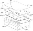
Fig. 1 shows a household appliance 62a comprising a household appliance device in a schematic front view. The household appliance 62a is embodied as a refrigerator. The household appliance 62a may also be embodied as a climate cabinet, an ice bin, a freezer, a combined refrigerator-freezer and/or a wine cooler. Alternatively, the household appliance 62a may be a household appliance for heating, in particular cooking, food, such as an oven, a steamer and/or a microwave oven. The household appliance device comprises a housing 138 a. The home appliance device includes an inner container 10 a. The inner container 10a is disposed within the receiving case 138 a. The household appliance device comprises a storage space 12 a. The inner container 10a defines a storage space 12 a. The home appliance device includes a door 140a for closing the storage space 12 a. The storage space 12a is divided into at least two storage areas 142a, 144a, i.e. a first storage area 142a and a second storage area 144 a. The first storage region 142a is configured to store humidity-sensitive foods, such as vegetables and fruits. The second storage area 144a is configured for storing packaged and/or moisture insensitive food.
The household appliance device comprises a container 14 a. The container 14a is at least partially arranged in at least one operating state within the storage space 12a, in particular within the first storage region 142 a. The container 14a is movably arranged within the storage space 14a and in particular is extractable from the storage space. The container 14a may be arranged in at least two positions, a first position and a second position. The first position is a storage position. In the first position, the container 14a is configured for storing food. The second position is a use position. In the second position, the receptacle 14a is configured for receiving food. In fig. 1, the container 14a is arranged in a first position. The container 14a can be made of plastic, in particular transparent plastic, and/or of metal.
Fig. 2 and 3 show a part of the household appliance device comprising the insert 82a and the container 14a in an exploded view and in a sectional view. The container 14a includes an opening 60 a. The opening 60a is configured for receiving food stored within the container 14a and/or for enabling access to food stored within the container 14 a. In the mounted position, in particular in the first position of the container 14a, the opening 60a of the container 14a faces the ceiling of the inner container 10 a. The container 14a is embodied as a drawer. The container 14a may be embodied as a box and/or a box or any other type of receptacle configured to receive and store food as deemed advantageous by one skilled in the art. Alternatively or additionally, the container 14a may include additional openings that are different from the opening 60a of the container 14a and that are specifically configured for receiving food stored within the container 14a and/or for enabling access to food stored within the container 14 a. In the present example, the household appliance device comprises only one container 14 a. Additionally, the household appliance device may also comprise a different number of containers 14a, which is considered advantageous by the person skilled in the art.
The insert 82a may be inserted into the storage space 12 a. Insert 82a is removably secured to bladder 10 a. The insert 82a divides the storage space 12a into two storage areas 142a, 144a (see fig. 1). In the present example, the insert 82a is embodied as a partition plate. Alternatively or additionally, the insert 82a may be embodied as a shelf and/or as a bottle holder. The insert 82a is configured to regulate humidity within the container 14 a. The insert 82a comprises a plurality of substructures of the household appliance device. In the mounted position, in particular in the first position of the container 14a, the opening 60a of the container 14a faces the insert 82 a.
The household appliance device comprises a manual actuator 16 a. The manual actuator 16a is accommodated within a receiving part 20a of the household appliance device. The manual actuator 16a is configured to regulate humidity within the container 14 a. The manual actuator 16a regulates the flow of air between the interior of the container 14a and the exterior of the container 14a, particularly the storage space 12 a. The manual actuator 16a is configured for adjusting the opening degree of the opening 60a of the container 14a, in particular by moving the cover 148a of the insert 82a relative to the container 14a, for adjusting the humidity level inside the container 14a (see fig. 2, 3 and 4). The degree of openness is related to the degree of uncovering of the surface area of the opening 60a of the container 14 a. Alternatively or additionally, manual actuator 16a may adjust pressure and/or temperature. The manual actuator 16a is also configured to be able to adjust the humidity based on manual input. To provide manual input, the manual actuator 16a includes a control element 46 a. The control element 46a is movable.
Fig. 4 shows the insert 82a and the container 14a in an exploded view. The lid 148a is configured for at least partially closing the opening 60a of the container 14a, in particular for adjusting the humidity within the container 14 a. In addition, the lid 148a is configured to enable light to shine into the container 14a and/or out of the container 14 a. For this purpose, the cover 148a may be at least partially, preferably largely and advantageously completely translucent, preferably transparent. The lid 148a may include a window 150a configured to enable light to shine into the container 14a and/or out of the container 14 a. The window 150a is made of an at least translucent, preferably transparent, material. The window 150a is rectangular. The window 150a extends over at least 20% of the major dimension of the cover 148 a. The window 150a is disposed below the lighting unit 18a of the home appliance device so as to enable light emitted by the lighting unit 18a to be irradiated to the inside of the container 14 a. In this example, the cover 148a includes two windows 150 a. The window 150a is arranged on the opposite side, viewed in a direction perpendicular to the main direction of extension of the cover 148 a. The windows 150a are mirror images of each other. Alternatively or additionally, the household appliance device may comprise a different number of windows, which is considered advantageous by the person skilled in the art. The cover 148a is movably coupled to the frame 22a of the home appliance device.
In the installed position, the frame 22a is disposed within the storage space 14 a. Further, in the mounted position, the frame 22a is detachably fixed to the inner container 10 a. The frame 22a is independent of any other unit of the household appliance device. The frame 22a is configured for connecting further substructures of the insert 82a to each other. The frame 22a at least partially surrounds at least one further unit of the household appliance device, in particular the receiving part 20a of the household appliance device, as viewed in a direction perpendicular to the frame 22 a.
The insert 82a includes a receiver 20 a. In the mounting position, the receiving member 20a is detachably fixed to the frame 22 a. The receiving part 20a is configured for receiving at least one further unit of the household appliance device. The receiver 20a includes a housing 152 a. The further unit is accommodated within the housing 152 a. The housing 152a is embodied in particular as a containment shell. The receiving element 20a is at least partially open on at least one side 36 a. In the mounted state of the household appliance device, the at least partially open side 36a is the upper side of the receptacle 20 a. The at least partially open side 36a is covered by a closing plate 42a of the household appliance device. The receiver 20a may be made of plastic and/or metal.
The insert 82a includes a closure plate 42 a. The closing plate 42a is embodied in particular as a shelf, which is configured in particular for storing food. The closing plate 42a is connected to the frame 22a of the insert 82 a. The frame 22a supports a closing plate 42 a.
Fig. 5 shows the frame 22a, the receiving part 20a and the lighting unit 18a of the domestic appliance in a perspective view. The illumination unit 18a is configured to illuminate the interior space of the container 14 a. The lighting unit 18a is accommodated within the receiving member 20a, in particular within the housing 152 a. The illumination unit 18a includes an illumination device 156 a. The lighting unit 18a comprises in particular a printed circuit board on which the lighting device 156a is arranged. The illumination device 156a includes a light source. In the present example, the light sources are implemented as LEDs. Alternatively or additionally, the light source 152a may be implemented as an OLED and/or a display. The illumination device 156a faces the container 14 a. The illumination device 156a is arranged such that the main illumination direction of the illumination device 156a forms an angle of 0 ° to 90 ° with the horizontal plane, in particular the main dimension plane of the receiving member 20 a. The receiver 20a includes a lighting opening 158a on the underside of the receiver 20 a. The illumination device 156a illuminates light into the interior space of the container 14a through the illumination opening 158 a. The receptacle 20a comprises in particular an illuminating cover 159 a. The illumination cover 159a is configured to protect the illumination device 156 a. The illuminating cover 159a is at least partially translucent, preferably transparent. Alternatively or additionally, the receiver 20a may be at least partially translucent, preferably transparent. The illumination unit 18a includes two illumination devices 156 a. The lighting device 150a is arranged on the opposite side of the receiving member 20a as viewed in a direction perpendicular to the major dimension direction of the receiving member 20 a.
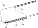
Fig. 6 to 10 show a part of a household appliance device in different views. The household appliance device comprises at least one separate fixing unit 88a (see fig. 9). The insert 82a is fixed to the inner container 10a by means of said fixing unit 88 a. The insert 82a includes a receiving recess 84 a. The frame 22a defines a receiving recess 84a (see fig. 8). The receiving recess 84a is at least partially surrounded by the frame 22a on at least three sides. The accommodating recess 84a is configured to at least partially accommodate the fixing unit 88 a. The receiving recess 84a includes a receiving opening 96a configured for receiving the fixed unit 88a when assembled. In the mounted state of the household appliance device, the receiving opening 96a faces the side wall of the inner container 10 a. Further, the accommodation recess 84a includes a through opening 98 a. In the mounted state of the household appliance device, the through opening 98a faces the bottom wall of the inner container 10 a. The opening surface of the receiving opening 96a, in particular of the receiving opening 96a, is in particular at least substantially larger than the opening surface of the through opening 98a, in particular of the through opening 98 a. The receiving opening 96a and the through opening 98a are connected on one side. The receiving opening 96a and the through opening 98a have opening directions 100a, 102a which are at least substantially perpendicular to one another. The insert 82a comprises two receiving recesses 84a, which are located on opposite sides of the insert 82a, viewed in a direction perpendicular to the major dimension of the insert 82 a.
The insert 82a includes an assembly element 104 a. The assembly element 104a is realized integrally with the frame 22 a. The assembly member 104a is accommodated in the accommodation recess 84 a. The assembly element 104a is at least configured for connecting the fixing unit 88a to the insert 82 a. The assembly member 104a includes a peg 176 a. The peg 176a has a catch 178 a. The catch 178a is configured for fixing the fixing unit 88a to the insert 82a, in particular in a direction at least substantially parallel to the opening direction 100a of the receiving opening 96 a.
The fixed unit 88a is implemented as a one-piece unit. The fixing unit 88a has a fixing member 92 a. The securing element 92a is configured for detachably securing the insert 82a to the inner bladder 10 a. The securing elements 92a are at least substantially hook-shaped. The fixation element 92a includes a head. The head is inclined relative to the major dimension of the fixation element 92 a. The angle between the head of the fixation element 92a and the major dimension direction is at least 270. When the insert 82a is fixed to the inner container 10a, the fixing element passes through the through opening 98 a.
The fixed unit 88a includes a support member 106 a. The bearing element 106a is connected to the assembly element 104a of the insert 82a, in particular via a snap 178 a. The support element 106a is configured for pivoting the fixing element 92a about a pivot axis 108 a. The pivot axis 108a is in particular at least substantially parallel to the opening direction 100a of the receiving opening 96 a. Advantageously, the pivot axis 108a is an axis of symmetry of the assembly element 104a, in particular of the peg 176a and/or of the support element 106 a. The peg 176a and the support element 106a form in particular a support unit. The fixing unit 88a includes an elastic member 110 a. The resilient element 110a is configured to resist rotation of the fixed element 92a about the pivot axis 108 a. The elastic element 110a is implemented as a bow spring.
The fixing unit 88a is at least largely arranged within the accommodation recess 84 a. The fixing element 92a is configured to fix the insert 82a to the liner 10a when the insert 82a is pushed into the storage space 12a in the pushing direction 94a of the insert 82 a. Furthermore, in the secured position of the insert 82a, the securing element 92a prevents any movement of the insert 82a at least in the insertion direction 94a and/or in the opposite direction, in particular in the withdrawal direction. The household appliance device comprises two separate fixing units 88a arranged in opposite receiving recesses 84 a.
The household appliance device comprises a snap edge 112a (see fig. 10). The snap edge 112a is coupled to the liner 10 a. The catch edge 112a is configured for connection with the fixing element 92 a. When assembled, the securing element 92a snaps into the snap edge 112 a. The fixing element is fixed in the snap edge 112a by the elastic element 110 a. For disassembly, the securing element 92a may be deflected by the user against the resilient element 110 a. The snap edge 112a is disposed on the sidewall of the liner 10 a. The household appliance device may comprise a guiding element 180 a. The guide element 180a is configured for guiding the insert 82a in the insertion direction 94a when the insert 82a is inserted into the storage space 12 a. The guide element 180a includes a catch edge 112 a. The guide elements 112a are arranged at the side walls of the inner container 10. The guide elements 112a are embodied as rails. The guide element 112a can preferably be embodied integrally with the inner container 10 a. The household appliance device comprises two guide elements 180a arranged on opposite sides of the liner 10 a.
Further exemplary embodiments of the present invention are shown in fig. 11 to 32. The following description is essentially limited to the differences between the exemplary embodiments, wherein for structural elements, features and functions that remain unchanged reference is made to the description of the further exemplary embodiments, in particular the exemplary embodiments of fig. 1 to 10. To distinguish the exemplary embodiments, the letter a of the reference numerals in the exemplary embodiments of fig. 1 to 10 has been replaced by the letters b to g of the reference numerals in the exemplary embodiments of fig. 11 to 32. For structural elements having the same name, in particular for structural elements having the same reference numerals, reference is mostly made to the drawings and/or the description of further exemplary embodiments, in particular of the exemplary embodiments of fig. 1 to 10.
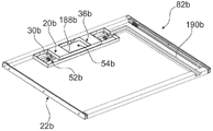
Fig. 11 to 14 show a further exemplary embodiment of a domestic appliance device. In this embodiment, the receiver 20b is configured for housing the lighting unit and the manual actuator. The receptacle 20b includes at least two compartments 52b, 54b, a first compartment 52b and a second compartment 54 b. The first compartment 52b is configured for at least partially housing the lighting unit. The second compartment 54b is configured for at least partially housing a manual actuator. The first compartment 52b at least partially surrounds the second compartment 54 b. In this embodiment, the upper side of the receiver 20b is completely open. The receiver 20b is tray-shaped. The receiver 20b includes a base plate 188 b. The receiver 20b includes an outer wall 30 b. The outer wall 30b is disposed on a bottom plate 188 b. The height of the outer wall 30b is at least substantially greater than the thickness of the bottom plate 188 b.
Furthermore, the household appliance device comprises a guide passage 190 b. The guide passage 190b is configured for connecting the lighting unit to a control unit of the home appliance device. A cable for connecting the lighting unit may be disposed within the guide channel 190 b. The guide passage 190b protects the wiring from external influences, such as moisture.
The receiver 20b includes an illumination opening 158 b. The receiver 20b includes an illumination cover 159 b. In this example, the illuminating cover 159b comprises two fixing elements. The receiving part 20b further comprises additional fixing elements. The further fixing elements are at least partly shaped to correspond to the fixing elements of the illuminating cover 159 b. The lighting cover 159b is fixed to the bottom plate 188b of the receiving part 20b by the fixing element and the additional fixing element.
Fig. 15 shows a construction kit 80b for a domestic appliance device in a schematic view. The building kit 80b is configured for building a household appliance device. Build kit 80b includes frame 22 b. Build kit 80b includes first module 76 b. Build kit 80b also includes second module 78 b. The first module 76b includes a manual actuator. In addition, the first module 76b also includes a receiver 20 b. The receiver 20b at least partially houses a manual actuator. The receiver 20b may be fixed to the frame 22 b. Preferably, the receiving part 20b only accommodates the manual actuator. The first module 76b advantageously does not have any lighting unit for illuminating the interior space of the container. The second module 78b includes an additional manual actuator. In addition, the second module 78b also includes a lighting unit. The second module 78b includes a receiver 20 b. The receiver 20b at least partially houses the lighting unit and at least partially houses the manual actuator. The receiver 20b may be fixed to the frame 22 b.
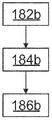
Fig. 16 shows a schematic illustration of a method for constructing a domestic appliance device. In method step 182b, frame 22b is provided. In a further method step 184b, the first module 76b and/or the second module 78b are provided. In a further method step 186b, the first module 76b or the second module 78b is fixed to the frame 22 b. Alternatively or additionally, the module 76b, 78b or a plurality of first and second modules 76b, 78b and the frame 22b may be provided for manufacturing a domestic appliance apparatus. Thus, different home appliances having different masses and values can simply be constructed with the same construction kit 80 b. Furthermore, a number of necessary components can be reduced.
Fig. 17 to 19 show a further embodiment of a domestic appliance device comprising a receptacle 20c and a frame 22c in different views. Receiver 20c includes a latch element 24 c. The snap-lock element 24c is configured for securing the receiver 20c to the frame 22 c. The catch element 24c is deformable. The catch element 24c is at least partially deformable in a direction at least substantially perpendicular to the main dimension direction of the receiving element 20c and/or the frame 22 c. The latching element 24c is arranged at the front side of the receptacle 20c, viewed in the mounted state of the household appliance arrangement. The outer wall 30c of the receiving element 20c is at least partially formed integrally with the latching element 24 c. The latch element 24c includes a snap hook 192 c. Latch element 24c includes a deformable latch arm 194 c. Snap arm 194c is connected to snap hook 192 c. Adjacent to the catch element 24c, the outer wall 30c is at least partially embodied separately from the base 188c of the receiver 20 c.
The receiver 20c includes a retaining element 26 c. The receiver 20c includes an additional retaining element 28 c. The holding element 26c and the further holding element 28c are at least substantially identical to each other. The holding member 26c is described in detail below. The description of the holding element 26c can be transferred correspondingly to the further holding element 28 c. The retaining element 26c is configured for securing the receiver 20c to the frame 22 c. The holding element 26c is arranged at the front side of the receiver 20c, viewed in the mounted position. The holding element 26c has a higher rigidity than the latching element 24 c. Furthermore, the holding element 26c may be embodied at least partially by the outer wall 30 c. The retaining element 26c includes an embedded element 196 c. Embedded element 196c is circular. Retaining member 26c includes a notch 198 c.
The frame 22c includes a fixing recess 64c (see fig. 18). The retaining recess 64c is at least partially shaped to correspond to the catch element 24 c. The frame 22c also includes a retaining recess 66 c. The retaining recess 66c is at least partially shaped to correspond to the retaining element 26 c. The frame 22c also includes an additional retaining recess 66 c. The further retaining recess 66c is at least partially shaped to correspond to the further retaining element 28 c. The retaining recess 66c and the further retaining recess 68c are at least substantially identical. In the following description, the holding recess 66c is described in detail. The description of the retaining recess 66c may correspondingly be transferred to the further retaining recess 68 c. The retaining recess 68b is at least substantially circular. The holding recess 66c has an insertion portion 70 c. The insert part 70c is designed to receive the holding element 26c, in particular the insert element 196c of the holding element 26 c. The insert 70c is at least partially circular. The holding recess 66c has a holding portion 72 c. The holding portion 72c is at least partially circular. The embedding portion 70c and the holding portion 72c are connected, thereby forming a single opening in particular. The retaining recess 66c is configured for fixing the retaining element 26c, in particular the recess 198c, in the preferably retaining portion 72c in a form-fitting manner.
In one assembly step, the retaining recess 66c receives the retaining element 26c when the frame 22c and the receiver 20c are moved towards each other, preferably at least substantially perpendicular to each other. In a further assembly step, the fixing recess 64c captures the catch element 24c when the frame 22c and the receiver 20c are moved alongside one another, preferably at least substantially parallel to one another. In the assembled state, the fixing recess 64c is configured for fixing the snap hook 192c of the catch element 24c in place.
In a disassembly step, the holding recess 64c releases the catch element 24c when the catch element 24c is pushed towards the receiver 20 c. In a further disassembly step, the retaining recess 66c releases the retaining element 26c when the frame 22c and the receiver 20c are moved alongside one another, preferably at least substantially parallel to one another.
Fig. 20 to 27 show a further embodiment of a domestic appliance device comprising a receptacle 20d and a frame 22d in different views. In the present example, the retaining element 26d of the receiving part 20d is at least substantially wedge-shaped. The retaining recess 66d of the frame 22d is at least substantially L-shaped. The retaining recess 66d includes an embedded portion 70 d. The insert 70d is at least substantially rectangular in shape. Further, the holding recess 66d includes a holding portion 72 d. The holding portion 72d is at least substantially rectangular in shape.
Fig. 22 shows an exploded view of the receiver 20d, manual actuator 16d and lighting unit 18 d. The lighting unit 18d is housed within the first compartment 52d of the receiver 20 d. The manual actuator 16d is at least partially received within the second compartment 54d of the receiver 20 d.
The manual actuator 16d includes a sub housing case 162d (see fig. 23). In the mounted state, the control element 46d of the manual actuator 16d is movably accommodated within the sub-accommodation case 162 d. The closing plate 42d of the household appliance device comprises a receiving recess 44d (see fig. 25). The sub-receiving shell 162d may be secured to the closing plate 42d in a force-fitting manner. In the mounted position, the receiving recess 44d receives the sub-accommodation shell 162d, in particular together with the control element 46 d. The control element 46d is at least substantially flush with the upper surface of the closing plate 42 d. The guide member 118d is connected to the sub-accommodation case 162 d.
The manual actuator 16d also includes an indicator member 164 d. The indicating element 164d is movably arranged between the control element 46d and the guide element 118 d. The indicating member 164d is connected to the control member 46 d. The bolt 208d of the control element 46d engages into the indicator element 164 d. The indicator element 164d is configured to be able to display the position of the control element 46d relative to the guide element 118d, in particular to be able to display the humidity in the container corresponding to the position of the control element 46 d. The indicating element 164d includes at least two indicators of at least two positions relative to the control element 46 d. In the present example, the two positions correspond to the control element 46d stopping at each end of the guide element 118 d. The indicator element 164d may be made of plastic, metal, and/or plastic-coated metal. The indicator is embodied in particular as a print, in particular on a sheet or on an extruded metal, as a separate element fixed with glue and/or as a stamping.
The manual actuator 16d includes a direction conversion unit 168 d. The direction conversion unit 168d is configured to convert, at least in part, a movement of the control element 46d parallel to the horizontal plane, in particular in the third direction 124d, into a previous movement of the control element 46d in a further direction parallel to the horizontal plane, in particular at least substantially perpendicular to the horizontal plane, preferably in the first direction 120 d. The direction conversion unit 168d includes a conversion guide member 172 d. The control element 46d is movably coupled to the transition guide element 172 d. The bolt 208d engages into the conversion guide element 172 d. The transition guide member 172d is inclined with respect to the guide member 118 d. The guide element 118d forms an angle with the transition guide element 172d between 0 ° and 90 °. The manual actuator 16d includes a coupling 170d configured to couple the direction switch unit 168d to a cover 148d configured to close the opening of the container. The coupling 170d is connected to the direction conversion unit 168 d. The coupling 170d is implemented integrally with the direction conversion unit 168 d. The direction conversion unit 168d transmits the movement of the control element 46d to the cover 148 d. By a movement of the control element 46d, in particular in the third direction 124d, the cover 148d is moved in the other direction, in particular at least in the first direction 124 d. The switching guide elements 172a are embodied as rails.
The manual actuator 16d includes an adapter connector 166 d. The adapter connector 166d connects the further unit of the manual actuator 16d, in particular the control element 46d, the sub-receiving shell 162d, the indicating element 164d, the guide element 118d and/or the direction switching unit 168d, to the receiving part 20 d.
In the following description, an exemplary assembly of the manual actuator 16d is described. When assembled, the guide member 118d is connected to the sub-accommodation case 162 d. The sub-receiving shell 162d engages in the receiving recess 44d of the closure plate 42d, in particular with the guide element 118d in the receiving recess 44d of the closure plate 42 d. The adapter connector 166d is arranged at least partially over the sub-receiving shell 162d and in particular the guide element 118 d. The indicator member 164d slides into the adapter connector 166 d. In particular, the indicating member 164d slides between the guide member 118d and the sub-accommodation case 162 d. The direction-switching unit 168d, in particular the switching guide element 172d, is arranged below the adapter connector 166d and preferably on top of the base plate 188a of the receiver 20 d. The control member 46d is embedded in the sub-accommodation case 162 d. The bolt 208d of the control element 46d engages into the indicator element 164d, the guide element 118d and the changeover guide element 172 d. The receiver 20d includes a through recess 38 d. When assembled, the connection head 210d of the manual actuator 16d engages into the through recess 38d, in particular into the switching guide element 172d of the direction switching unit 168 d. The connector 210d is connected to the bolt 208d of the control element 46 d. In this example, the bolt 208d and the connector 210d may form a threaded connection and/or a riveted connection. Alternatively or additionally, the connector 210d and the bolt 208d may be glued together. In the mounted state, the manual actuator 16d is fixed to the closing plate 42d and the receiver 20d, in particular by the connection between the bolt 208d and the connecting head 210 d. The coupling 170d of the direction switching unit 168d passes through the additional through recess 39d of the receiving piece 20 d. The coupling 170d engages the cap 148 d. Manual actuator 16d includes an additional connector 212 d. The additional connector 212d connects the coupling 170d to the cap 148 d.
In the operating state of the domestic appliance arrangement, the control element 46d can slide along the guide element 118d, in particular along the third direction 124 d. By movement of the control element 46d, the bolt 208d is moved. The bolt 208d extends within the switch guide member 172d of the direction switch unit 168 d. The transition guide element 172d is deflected by the bolt 208 d. Thus, the direction conversion unit 168d is moved in a direction at least substantially perpendicular to the direction of movement of the control element 46d, in particular in the first direction 120 d. The link 170d couples the movement of the direction conversion unit 168d to the cover 148 d.
The guiding unit 174d of the frame 22d comprises a profile 200 d. The profile 200d has an inclination with respect to the frame 22 d. The guide unit 174d is thus configured to be able to convert a movement of the cover 148d in the first direction 120d, in particular at least substantially parallel to the horizontal plane of the household appliance device in the mounted position, at least partially into a movement of the cover 148d in the second direction 122d, in particular at least substantially perpendicular to the horizontal plane of the household appliance device in the mounted position. Through the interaction of the manual actuator 16d and the guiding unit 174d, the movement of the control element 46d in the third direction 124d is converted into a movement of the cover 148d in the second direction 122 d. The movement of the control element 46d, in particular in the third direction 124d, is converted by the direction conversion unit 168d into a movement of the cover 148d, in particular in the first direction 120 d. The guiding unit 174d converts a movement of the cover 148d, in particular in the first direction 120d, at least substantially perpendicularly, in particular into a movement in the second direction 122 d.
The manual actuator 16d defines at least one lock-in position 114d (see fig. 24) of the control element 46 d. The lock-in position 114d corresponds in particular to a preferably factory-set humidity level within the container. The control element 46d is configured to be non-destructively released from the lock-in position 114d when a force acting on the control element 46d exceeds a holding force holding the control element 46d in the lock-in position 114 d. The manual actuator 16d includes at least one catch element 126d configured for locking the control element 46d in the locked position 114 d. The catch element 126d is deformable in particular in a direction at least substantially parallel to a horizontal plane of the household appliance device in the mounted position. The catch element 126d is deformable. The catch element 126d is deformable in a direction at least substantially perpendicular to the direction of movement of the control element 46 d. The manual actuator 16d comprises at least one further catch element 128 d. The further catch element 128d is located opposite the catch element 126 d. The further catch element 128d is deformable in a direction opposite to the direction in which the catch element 126d is deformable. The further catch element 128d is mirror-symmetrical with respect to the catch element 126 d. The further catch element 128d is at least substantially identical in design to the catch element 126 d. For greater clarity, only one of the snap elements 126d is described in detail below. The following description may correspondingly be transferred to the further catch element 128 d.
The catch element 126d comprises two guiding ramps 130d, 132d, namely a first guiding ramp 130d and a second guiding ramp 132 d. The first guide ramp 130d is configured for contacting the control element 46 d. The first guide ramp 130d is configured for deforming the catch element 126d in the event of a movement of the control element 46d in the first direction of movement and when the control element 46d exerts a force on the first guide ramp 130 d. The second guide ramp 132d is configured for contacting the control element 46 d. The second guide ramp 132d is configured for deforming the catch element 126d in the event of a movement of the control element 46d in a second direction of movement, in particular a second direction of movement opposite to the first direction of movement, and when the control element 46d exerts a force on the second guide ramp 132 d. The guide ramps 130d, 132d accordingly form an angle of between 0 ° and 90 °, preferably between 0 ° and 75 °, advantageously between 0 ° and 45 °, with the direction of movement of the control element 46 d. The guide element 118d of the manual actuator 16d is embodied integrally with the catch elements 126d, 128 d.
The manual actuator 16d defines a further lock-in position 116d for the control element 46 d. The further lock-in position 116d is at least substantially identical to the lock-in position 114d, in particular is embodied as described above. The locked-in positions 114d, 116d correspond to two different positions indicated by the indicator member 164 d. The locked-in positions 114d, 116d correspond to at least one humidity level within the container, respectively. The lock-in position 114d corresponds to a maximum humidity level within the container. The maximum humidity level corresponds in particular to the minimum opening degree of the container opening. In particular, a minimum opening degree is achieved when the surface of the opening is at least largely, advantageously completely, covered. The further lock-in position 116d corresponds to a maximum humidity level within the container. The further lock-in position 116d corresponds to a minimum humidity level within the container. The minimum humidity level corresponds in particular to the maximum opening degree of the opening of the container. Advantageously, the maximum opening degree is reached when the surface of the opening of the container is at least largely, advantageously completely, uncovered.
Fig. 28, 29 show a further embodiment of a domestic appliance device. The receptacle 20e of the household appliance device comprises a protective inner barrier 48 e. The protective inner barrier 48e is disposed within the receiver 20 e. The protective inner barrier 48e is distinguishable from the outer wall 30 e. The protective inner barrier 48e particularly extends at least partially from the floor 188e of the receptacle 20e to the closure panel.
The protective inner barrier 48e separates the receptacle 20e into two compartments 52e, 54e, a first compartment 52e and a second compartment 54 e. The first compartment 52e is configured for at least partially housing the lighting unit. The second compartment 54e is configured for at least partially housing a manual actuator. Further, the receiver 20e includes an additional protective inner barrier 50 e. The protective inner barriers 48e, 50e are at least substantially identical. The protective inner barriers 48e, 50e are arranged within the receptacle 20e mirror-symmetrically to each other. The protective inner barriers 48e, 50e are arranged on opposite sides, viewed in a direction perpendicular to the major dimension direction of the receiver 20 e. For greater clarity, the protective inner barrier 48e is described in detail below. The following description may accordingly be transferred to the further protective inner barrier 50 e.
The inner barrier 48e includes at least two sidewalls 202e, 204e, a first sidewall 202e and a second sidewall 204 e. The first sidewall 202e bounds the first compartment 52 e. The second sidewall 204e faces away from the second compartment 54 e. In addition, the protective inner barrier 48e includes a vent passage 56 e. The sidewalls 202e, 204e at least partially define the discharge passage 56 e. The drain channel 56e may include a ramp configured to direct the condensed water away from the lighting unit. The protective inner barrier 56e also includes a drain 206 e. The discharge portion 206e is connected to the discharge passage 56 e. The drain 206e is configured for conveying condensate away from the receiver 20 e. The discharge portion 206e is embodied as an opening in the receptacle 20e, in particular in the base plate 188e of the receptacle 20 e.
Fig. 31 and 32 show a further exemplary embodiment of a domestic appliance device. In the present example, the direction conversion unit 168f of the manual actuator 16f is at least partially realized integrally with the cover 148f of the household appliance device. The switching guide element 172f of the direction switching unit 168f is embodied as a recess of the cover 148 f. Furthermore, the guide element 118f of the manual actuator 16f is realized integrally with the adapter connector 166f of the manual actuator 16 f. When assembled, the sub-receiving shell 162f of the manual actuator 16f may be slid into the mating connector 166 f. Furthermore, the coupling of the manual actuator 16f is implemented separately from the switching guide element 172 f.
Fig. 33 shows a further exemplary embodiment of a domestic appliance apparatus. In the present example, the guide element 118g of the manual actuator 16g is embodied integrally with the adapter connector 166g of the manual actuator 16 g.
List of reference numerals
10 inner container 72 holding part
12 storage space 76 first module
14 container 78 second module
16 manual actuator 80 construction kit
18 Lighting Unit 82 insert
20 receiver 84 receiving recess
22 frame 88 fixing unit
24 latch element 92 securing element
26 retaining element 94 push-in direction
28 holding element 96 receiving opening
30 outer wall 98 through opening
36 open side 100 opening direction
38 in the direction of opening of through recess 102
39 further through recess 104 assembly element
42 closure plate 106 support element
44 receiving recess 108 pivot axis
46 control element 110 resilient element
48 protective inner barrier 112 snap edge
50 protective inner barrier 114 into position
52 first compartment 116 locked into position
54 second compartment 118 guide element
56 first direction of discharge passage 120
60 second direction of opening 122
62 household appliance 124 third direction
64 securing recess 126 snap element
66 retaining recess 128 snap element
70 insert 130 guide ramp
132 guide ramp 196 insert element
138 housing 198 recess
140 door 200 section bar
142 first storage area 202 first sidewall
144 second side wall of second storage area 204
148 cover 206 drain
150 window 208 bolt
152 housing 210 connector
154 coupling element 212 further connector
156 lighting device
158 illumination opening
159 Lighting cover
162 seed holding case
164 indicating element
166 adapting connector
168 direction conversion unit
170 coupling piece
172 switching guide element
174 guide unit
176 bolt
178 fastener
180 guide element
182 method step
184 method step
186 method step
188 bottom plate
190 guide way
192 snap hook
194 arm buckle
Claims (12)
1. A construction kit for constructing a household appliance device, the household appliance device comprising: an inner container (10a) defining a storage space (12 a); and a container (14a) arranged within the storage space (12a), wherein the construction kit comprises:
a frame (22 a; 22 b; 22 d; 22 f);
a first module (76b) comprising: a manual actuator (16 a; 16 d; 16 f; 16g) configured for adjusting the humidity inside the container (14 b); and a receiver (20a-20f) which at least partially houses the manual actuator (16 a; 16 d; 16 f; 16g) and which is fixable to the frame (22 a; 22 b; 22 d; 22 f); and
a second module (78b) comprising: a manual actuator (16 a; 16 d; 16 f; 16g) configured for adjusting the humidity inside the container (14 b); an illumination unit (18 a; 18 c; 18d) configured for illuminating the interior space of the container (14 b); and a receiving part (20a-20f) which at least partially accommodates the lighting unit (18 a; 18 c; 18d) and at least partially accommodates the manual actuator (16 a; 16 d; 16 f; 16g) and which is fixable to the frame (22 a; 22 b; 22 d; 22f), wherein,
the frame can at least partially surround the receiver.
2. The building kit according to claim 1, wherein the domestic appliance device is a domestic refrigeration appliance device.
3. Construction kit according to claim 1 or 2, characterized in that the receiver (20a-20f) comprises a deformable latching element (24 a; 24 d; 24e) and a retaining element (26a, 28 a; 26d, 28 d; 26e, 28e) which has a higher rigidity than the latching element (24 a; 24 d; 24e), the latching element (24 a; 24 d; 24e) and the retaining element (26a, 28 a; 26d, 28 d; 26e, 28e) being configured for fixing the receiver (20a-20f) to the frame (22 a; 22 b; 22 d; 22 f).
4. Construction kit according to claim 3, wherein the receiving elements (20a-20f) comprise outer walls (30b-30e) at least partially implementing the snap-lock elements (24 a; 24 d; 24 e).
5. Construction kit according to claim 3, characterized in that the frame (22 a; 22 b; 22 d; 22f) comprises a fixing recess (64 d; 64e) which is at least partially shaped to correspond to the catch element (24 a; 24 d; 24e), and a retaining recess (66d, 68 d; 66e, 68e) which is at least partially shaped to correspond to the retaining element (26a, 28 a; 26d, 28 d; 26e, 28 e).
6. Construction kit according to claim 5, characterized in that the retaining recess (66d, 68 d; 66e, 68e) has an embedding (70 d; 70e) configured for receiving the retaining element (66d, 68 d; 66e, 68e) and a retaining (72 d; 72e) for fixing the retaining element (66d, 68 d; 66e, 68e) in a form-fitting manner.
7. Construction kit according to any one of claims 1-2, 4-6, characterized in that the receiving elements (20a-20f) are detachably securable to the frame (22 a; 22 b; 22 d; 22 f).
8. The building kit according to any one of claims 1-2, 4-6, wherein the container (14a) has an opening (60a), wherein the manual actuator (16 a; 16 d; 16 f; 16g) is configured for adjusting the degree of opening of the opening (60a) for adjusting the humidity inside the container (14 a).
9. The building kit according to any one of claims 1-2, 4-6, wherein the household appliance device further comprises a closing plate (42 a; 42 d; 42f) configured for at least partially closing the at least partially open side (36 a; 36 b; 36e) of the receptacle (20a-20 f).
10. A construction kit according to any one of claims 1-2, 4-6, wherein the frame (22 a; 22 b; 22 d; 22f) is detachably securable to the liner (10 a).
11. A method for manufacturing a household appliance device (62a) using a construction kit (80b) according to any one of claims 1-10, the method comprising the steps of: providing a frame (22 a; 22 b; 22 d; 22 f); providing a first module (76 b); providing a second module (78 b); and fixing the first module (76b) or the second module (78b) to the frame (22 a; 22 b; 22 d; 22 f).
12. A household appliance (62a), characterized in that it comprises a household appliance device manufactured by the method according to claim 11.
Applications Claiming Priority (5)
| Application Number | Priority Date | Filing Date | Title |
|---|---|---|---|
| TR201504908 | 2015-04-21 | ||
| TR2015/04908 | 2015-04-21 | ||
| TR2015/04910 | 2015-04-21 | ||
| TR201504910 | 2015-04-21 | ||
| PCT/EP2016/058581 WO2016169900A1 (en) | 2015-04-21 | 2016-04-18 | Home appliance device |
Publications (2)
| Publication Number | Publication Date |
|---|---|
| CN107532846A CN107532846A (en) | 2018-01-02 |
| CN107532846B true CN107532846B (en) | 2020-02-18 |
Family
ID=56081449
Family Applications (2)
| Application Number | Title | Priority Date | Filing Date |
|---|---|---|---|
| CN201680022168.XA Active CN107532846B (en) | 2015-04-21 | 2016-04-18 | Household appliance device |
| CN201680022167.5A Active CN107532845B (en) | 2015-04-21 | 2016-04-18 | Household appliance device |
Family Applications After (1)
| Application Number | Title | Priority Date | Filing Date |
|---|---|---|---|
| CN201680022167.5A Active CN107532845B (en) | 2015-04-21 | 2016-04-18 | Household appliance device |
Country Status (5)
| Country | Link |
|---|---|
| US (2) | US10852055B2 (en) |
| EP (2) | EP3286511B1 (en) |
| CN (2) | CN107532846B (en) |
| PL (2) | PL3286510T3 (en) |
| WO (2) | WO2016169899A1 (en) |
Families Citing this family (9)
| Publication number | Priority date | Publication date | Assignee | Title |
|---|---|---|---|---|
| CN106885435B (en) * | 2017-02-14 | 2019-06-28 | 合肥华凌股份有限公司 | Humidity regulation drawer and refrigerator |
| CN111076489B (en) * | 2019-03-08 | 2020-10-30 | 青岛海尔电冰箱有限公司 | Front panel assembly of drawer of refrigerator, drawer and refrigerator |
| CN110345703A (en) * | 2019-07-17 | 2019-10-18 | 澳柯玛股份有限公司 | A kind of preservation drawer and refrigerator of adjusting humidity |
| CN113324365B (en) * | 2020-02-28 | 2023-10-27 | 松下知识产权经营株式会社 | Refrigerator with a refrigerator body |
| CN115077153A (en) * | 2021-03-10 | 2022-09-20 | 博西华电器(江苏)有限公司 | Refrigeration device |
| CN115247926A (en) * | 2021-04-28 | 2022-10-28 | 博西华电器(江苏)有限公司 | Refrigerator and method for adjusting cover of drawer in refrigerating chamber |
| CN115247925A (en) * | 2021-04-28 | 2022-10-28 | 博西华电器(江苏)有限公司 | Refrigerator and method for adjusting cover of drawer in refrigerating chamber |
| CN115493341A (en) * | 2021-06-17 | 2022-12-20 | 博西华电器(江苏)有限公司 | Storage container comprising an air-conditioning device and household refrigeration appliance |
| DE102021206173A1 (en) * | 2021-06-17 | 2022-12-22 | BSH Hausgeräte GmbH | Food storage container, comprising an air conditioning device with a specific operating status display, and domestic refrigeration appliance |
Citations (5)
| Publication number | Priority date | Publication date | Assignee | Title |
|---|---|---|---|---|
| CN100538227C (en) * | 2005-04-04 | 2009-09-09 | 菲舍尔和佩克尔应用有限公司 | Humidity control lid |
| CN102483282A (en) * | 2009-09-02 | 2012-05-30 | Bsh博世和西门子家用电器有限公司 | Refrigeration device with a vegetable drawer |
| CN202254596U (en) * | 2011-08-17 | 2012-05-30 | 海尔集团公司 | Humidity regulator for refrigerators |
| CN203464599U (en) * | 2013-08-19 | 2014-03-05 | 海信容声(广东)冰箱有限公司 | Refrigerator lighting device |
| WO2014206807A1 (en) * | 2013-06-27 | 2014-12-31 | BSH Bosch und Siemens Hausgeräte GmbH | Domestic refrigerator having a keep-fresh container and an operating element designed in the form of a push/push locking mechanism for moving a cover for the keep-fresh container |
Family Cites Families (32)
| Publication number | Priority date | Publication date | Assignee | Title |
|---|---|---|---|---|
| US4013434A (en) * | 1976-04-05 | 1977-03-22 | General Motors Corporation | Hydrator drawer cover with adjustable moisture control damper |
| US4557118A (en) * | 1984-12-06 | 1985-12-10 | Amana Refrigeration, Inc. | Crisper humidity control |
| US4729613A (en) * | 1986-11-13 | 1988-03-08 | General Electric Company | Household refrigerator pan assembly |
| US5044704A (en) * | 1990-05-17 | 1991-09-03 | Whirlpool Corporation | Adjustable refrigerator crisper drawer structure |
| US5641217A (en) * | 1995-08-02 | 1997-06-24 | Sub-Zero Freezer Company, Inc. | Slide shelf system for a deli/crisper drawer |
| US6880949B2 (en) * | 2001-11-15 | 2005-04-19 | General Electric Company | Mullion assembly for refrigerator quick chill and thaw pan |
| KR100469468B1 (en) * | 2002-10-23 | 2005-02-02 | 엘지전자 주식회사 | Vegetable room optimum preservation apparatus for refrigerator |
| KR100524785B1 (en) * | 2002-10-23 | 2005-10-31 | 엘지전자 주식회사 | Vegetable room optimum preservation apparatus for refrigerator |
| KR20050072298A (en) * | 2004-01-06 | 2005-07-11 | 삼성전자주식회사 | Refrigerator |
| KR20050080684A (en) * | 2004-02-10 | 2005-08-17 | 삼성전자주식회사 | Refrigerator |
| EP1630500A2 (en) | 2004-08-26 | 2006-03-01 | Samsung Electronics Co., Ltd. | Refrigerator |
| US7147341B2 (en) | 2004-10-12 | 2006-12-12 | Illinois Tool Works Inc | Light assembly |
| JP3718215B2 (en) * | 2004-10-29 | 2005-11-24 | 松下冷機株式会社 | refrigerator |
| DE102005021591A1 (en) * | 2005-05-10 | 2006-11-16 | BSH Bosch und Siemens Hausgeräte GmbH | Household appliance with telescopic extension |
| DE202005021758U1 (en) * | 2005-05-10 | 2009-10-01 | BSH Bosch und Siemens Hausgeräte GmbH | Telescopic extension for a refrigeration device |
| US7685934B2 (en) * | 2005-10-25 | 2010-03-30 | Lg Electronics Inc. | Refrigerator and method for keeping food using the same |
| US8813516B2 (en) * | 2005-10-27 | 2014-08-26 | Lg Electronics Inc. | Refrigerator with visible light radiation |
| EP1949009B8 (en) | 2005-10-27 | 2020-06-03 | LG Electronics Inc. | Refrigerator |
| CN2881489Y (en) | 2006-01-18 | 2007-03-21 | 海尔集团公司 | Lighting device of refrigerator drawer |
| DE202006005548U1 (en) * | 2006-04-05 | 2006-06-14 | BSH Bosch und Siemens Hausgeräte GmbH | Refrigerating appliance with divided interior |
| US7670018B2 (en) | 2006-05-16 | 2010-03-02 | Lg Electronics Inc. | Illumination device for refrigerator and method of controlling the same |
| KR100719252B1 (en) * | 2006-07-03 | 2007-05-18 | 주식회사 대우일렉트로닉스 | Structure for assembling cover assembly and humidity control knob of vegetables box in refrigerator |
| JP2008089202A (en) * | 2006-09-29 | 2008-04-17 | Matsushita Electric Ind Co Ltd | Refrigerator |
| RU2473025C2 (en) * | 2007-10-09 | 2013-01-20 | Панасоник Корпорэйшн | Refrigerator |
| JP5359174B2 (en) * | 2007-10-31 | 2013-12-04 | パナソニック株式会社 | refrigerator |
| WO2009115277A2 (en) * | 2008-03-17 | 2009-09-24 | Aktiebolaget Electrolux (Publ) | An improved appliance such as a refrigerator, freezer or combination thereof |
| US9285157B2 (en) * | 2008-05-23 | 2016-03-15 | Aktiebolaget Electrolux | Cold appliance |
| KR101611283B1 (en) * | 2009-09-02 | 2016-04-26 | 엘지전자 주식회사 | A refrigerator having a decorating member capable of displaying humidity and a production method for the decorating member for the refrigerator |
| JP4983900B2 (en) | 2009-12-03 | 2012-07-25 | パナソニック株式会社 | refrigerator |
| KR101104567B1 (en) | 2009-12-18 | 2012-01-11 | 엘지전자 주식회사 | Drawer apparatus for refrigerator |
| US20140145579A1 (en) * | 2012-11-27 | 2014-05-29 | Whirlpool Corporation | Modular interface for pantry temperature control |
| DE102013212383A1 (en) | 2013-06-27 | 2014-12-31 | BSH Bosch und Siemens Hausgeräte GmbH | Domestic refrigeration appliance with a freshness container in an interior, which has a with a rotatable control element can be raised and lowered lid |
-
2016
- 2016-04-18 US US15/568,551 patent/US10852055B2/en active Active
- 2016-04-18 PL PL16717367T patent/PL3286510T3/en unknown
- 2016-04-18 EP EP16725039.8A patent/EP3286511B1/en active Active
- 2016-04-18 WO PCT/EP2016/058580 patent/WO2016169899A1/en active Application Filing
- 2016-04-18 US US15/568,607 patent/US10830530B2/en active Active
- 2016-04-18 CN CN201680022168.XA patent/CN107532846B/en active Active
- 2016-04-18 PL PL16725039T patent/PL3286511T3/en unknown
- 2016-04-18 EP EP16717367.3A patent/EP3286510B1/en active Active
- 2016-04-18 CN CN201680022167.5A patent/CN107532845B/en active Active
- 2016-04-18 WO PCT/EP2016/058581 patent/WO2016169900A1/en active Application Filing
Patent Citations (5)
| Publication number | Priority date | Publication date | Assignee | Title |
|---|---|---|---|---|
| CN100538227C (en) * | 2005-04-04 | 2009-09-09 | 菲舍尔和佩克尔应用有限公司 | Humidity control lid |
| CN102483282A (en) * | 2009-09-02 | 2012-05-30 | Bsh博世和西门子家用电器有限公司 | Refrigeration device with a vegetable drawer |
| CN202254596U (en) * | 2011-08-17 | 2012-05-30 | 海尔集团公司 | Humidity regulator for refrigerators |
| WO2014206807A1 (en) * | 2013-06-27 | 2014-12-31 | BSH Bosch und Siemens Hausgeräte GmbH | Domestic refrigerator having a keep-fresh container and an operating element designed in the form of a push/push locking mechanism for moving a cover for the keep-fresh container |
| CN203464599U (en) * | 2013-08-19 | 2014-03-05 | 海信容声(广东)冰箱有限公司 | Refrigerator lighting device |
Also Published As
| Publication number | Publication date |
|---|---|
| US20180112910A1 (en) | 2018-04-26 |
| EP3286510B1 (en) | 2020-08-12 |
| US20180156534A1 (en) | 2018-06-07 |
| EP3286510A1 (en) | 2018-02-28 |
| EP3286511A1 (en) | 2018-02-28 |
| CN107532846A (en) | 2018-01-02 |
| US10852055B2 (en) | 2020-12-01 |
| CN107532845B (en) | 2020-02-18 |
| PL3286511T3 (en) | 2021-01-11 |
| EP3286511B1 (en) | 2020-06-10 |
| US10830530B2 (en) | 2020-11-10 |
| PL3286510T3 (en) | 2021-02-08 |
| CN107532845A (en) | 2018-01-02 |
| WO2016169899A1 (en) | 2016-10-27 |
| WO2016169900A1 (en) | 2016-10-27 |
Similar Documents
| Publication | Publication Date | Title |
|---|---|---|
| CN107532846B (en) | Household appliance device | |
| US9823013B1 (en) | Home appliance device | |
| US20170131024A1 (en) | Domestic Refrigeration Appliance Having An Interior Lighting Arrangement | |
| EP3286509B1 (en) | Home appliance device | |
| US10151525B2 (en) | Harvest bin assembly | |
| US20190316837A1 (en) | Household refrigeration appliance with interior lighting and method for producing the household refrigeration appliance | |
| WO2016169897A1 (en) | Home appliance device | |
| AU2010218176B2 (en) | Basket kick-out | |
| US20100050677A1 (en) | Refrigeration appliance with an ice maker | |
| US9863690B1 (en) | Home appliance door | |
| US10132557B2 (en) | Home appliance device | |
| CN108113254B (en) | Household appliance device | |
| US11525620B2 (en) | Door insert, door of a household cooling appliance, and method for mounting a door insert | |
| US20160187055A1 (en) | Domestic Cooling Appliance Having At Least One Light Source And A Receiving Means For A Shelf | |
| EP3935329B1 (en) | Household cooling appliance with a door device comprising a cover | |
| WO2022263133A1 (en) | Storage container comprising an air conditioning device with specific operating device, as well as household cooling appliance | |
| CN214199371U (en) | Keeping device, system and household refrigeration appliance |
Legal Events
| Date | Code | Title | Description |
|---|---|---|---|
| PB01 | Publication | ||
| PB01 | Publication | ||
| SE01 | Entry into force of request for substantive examination | ||
| SE01 | Entry into force of request for substantive examination | ||
| GR01 | Patent grant | ||
| GR01 | Patent grant |