CN1075318C - Rear projection television - Google Patents
Rear projection television Download PDFInfo
- Publication number
- CN1075318C CN1075318C CN96120154A CN96120154A CN1075318C CN 1075318 C CN1075318 C CN 1075318C CN 96120154 A CN96120154 A CN 96120154A CN 96120154 A CN96120154 A CN 96120154A CN 1075318 C CN1075318 C CN 1075318C
- Authority
- CN
- China
- Prior art keywords
- rear projection
- projection television
- lower casing
- upper casing
- screen
- Prior art date
- Legal status (The legal status is an assumption and is not a legal conclusion. Google has not performed a legal analysis and makes no representation as to the accuracy of the status listed.)
- Expired - Fee Related
Links
Images


Classifications
-
- H—ELECTRICITY
- H04—ELECTRIC COMMUNICATION TECHNIQUE
- H04N—PICTORIAL COMMUNICATION, e.g. TELEVISION
- H04N5/00—Details of television systems
- H04N5/74—Projection arrangements for image reproduction, e.g. using eidophor
-
- H—ELECTRICITY
- H04—ELECTRIC COMMUNICATION TECHNIQUE
- H04N—PICTORIAL COMMUNICATION, e.g. TELEVISION
- H04N9/00—Details of colour television systems
- H04N9/12—Picture reproducers
- H04N9/31—Projection devices for colour picture display, e.g. using electronic spatial light modulators [ESLM]
- H04N9/3141—Constructional details thereof
Landscapes
- Engineering & Computer Science (AREA)
- Multimedia (AREA)
- Signal Processing (AREA)
- Projection Apparatus (AREA)
- Transforming Electric Information Into Light Information (AREA)
- Video Image Reproduction Devices For Color Tv Systems (AREA)
Abstract
One kind of housing has been formed for rear projection televisions of each screen size in inches and it has not been possible to change the size in inches for such a housing. This has reduced productivity and results in a cost increase. An upper cabinet and a lower cabinet of a rear projection television are formed separately. A screen and a mirror are provided on the upper cabinet. A main component portion for a television comprising video devices, driving and control circuits, an optical unit including a projection lens, and a light source is provided on the lower cabinet. Upper cabinets of different screen sizes in inches are assembled with a common lower cabinet to allow rear projection televisions of various sizes in inches to be easily manufactured.
Description
The present invention relates to rear projection television, it comprises: such as the video-unit of LCD (abbreviating LCD below this paper as), comprise projection lens, light source, speculum and like and have the optical system of the screen in mounted thereto front.
Because the screen of such rear projection television has the little characteristics of the big degree of depth of width, so compare with the TV that uses Braun tube, it is easier does more greatly.Rear projection television 1 as shown in Figure 1 comprises the structure that a wooden plate material of usefulness is done, and this plate material is made the box that constitutes main part 2; A screen installed part 4 that is installed in main part 2 fronts is equipped with screen 3 on it; The speculum installation portion 6 that speculum 5 is housed that is installed in the back; Integrally be installed in the drain pan 7 of bottom in the main part 2, its like that video-unit and electronic component is housed in it and is used for projection image.
Comprise at rear projection television shown in Figure 21: a structure that is erected at the metal framework that has pre-determined shape 8 on the drain pan 7; A screen installed part 4 and the speculum mounting portion 6 that speculum 5 is housed that screen 3 is housed, screen installed part 4 and anti-projecting mirror mounting portion 6 integrally are installed together, and they are surrounded framework 8 from the two sides, front and back.
In first example, screen installed part 4 and speculum mounting portion 6 are installed on the wooden main part 2 from the two sides, front and back respectively.Main part 2 and comprise that the overall dimensions of speculum mounting portion 6 all will determine according to screen size, when beginning each part of designed enclosures, the design of its size and dimensional accuracy thereof all is in order to make the single shell that an energy and video screen match, and dimensional units wherein is an inch.As a result, such parts can't be compatible mutually with the TV of other size that with the inch is unit.The problem that is caused like this, it is low to be not only production efficiency, and owing to will guarantee the predetermined strength of wooden main part 2, will strengthen slab-thickness inevitably and increase overall weight.
In second example, although used metal framework 8, it is designed to the shell with the matched single size of video screen size.As a result, it can not be compatible mutually with the TV of other size.Simultaneously, the use of metal framework 8 has not only caused the increase of whole weight, and owing to increased the quantity of associated components, has also caused more problem such as complexity and assembling device efficient step-down of management work.
And in each example, because shell is single parts, screen is with in speculum is installed in the outer casing space the same with other assembly.This makes them contact with flow air in this shell.But because dust and similar material are attached on it, screen and speculum are just dirty, the problem that has so more caused visual display quality to reduce.
So, in order to make shell can satisfy the video screen of different size, also to solve some problems, so that designs simplification becomes an integral body, improve the compatibility between different size, when guaranteeing that just optical accuracy is constant, make to be easy to produce, and quality descends because optical element is dirty to avoid image.
The purpose of this invention is to provide a kind of rear projection television, it has one not need the general lower casing that cooperates with video screen.
According to the present invention, rear projection television is made up of upper casing and two independent sectors of lower casing.Screen and speculum are arranged in the upper casing.Video-unit is arranged in the lower casing, drive and control circuit, and comprise the optics of projection lens, and light source.The focus of projection lens can be regulated according to the selected size of upper casing, and upper casing removably is installed on the lower casing.
Except the structure of introducing above, upper casing shape is as a box, the opening that its bottom has a projection lens to face, and all the other each faces all seal.There is an air inlet in the front of lower casing, and the extraneous air of air inlet inspiration from then on makes its inner cooling, also has a gas channel that is used for air-out that is positioned at its back.The removable filter device is arranged on the air inlet.The light resource installing section branch is positioned at the front of lower casing, and light source is removably mounted in the light resource installing section branch.
The structure of rear projection television makes it can be divided into upper casing and lower casing.The main element of TV partly is arranged in the lower casing, and screen and speculum then are positioned at upper casing.This makes upper casing have versatility, no matter and the video screen size how.Upper casing can have the video screen of virtually any size, and can be applicable to the video screen of various sizes by the focus that changes projection lens.Therefore, select suitable upper casing to make us be easy to make the rear projection television of various inch sizes.
Fig. 1 is the decomposition diagram of an example of rear projection television.
Fig. 2 is the decomposition diagram of another example of rear projection television.
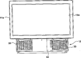
Fig. 3 is the front view according to the rear projection television of first embodiment of the invention.
Fig. 4 is the end view according to the rear projection television of first embodiment of the invention.
Fig. 5 is the rearview according to the rear projection television of first embodiment.
Fig. 6 is the simplified cross-sectional view according to the rear projection television of first embodiment, and its upper casing and lower casing are in released state.
Fig. 7 has illustrated the focusing principle of the projection lens in the rear projection television.
Fig. 8 has schematically illustrated the video-unit among first embodiment.
Fig. 9 is the front view according to the rear projection television of second embodiment of the invention.
Figure 10 is the end view according to the rear projection television of the 3rd embodiment.
Illustrated embodiment referring now to it is introduced the present invention in detail.The present invention is applicable to the rear projection television of any kind of.Yet here, we describe the liquid crystal rear projection television in detail as an example.The liquid crystal rear projection television of first embodiment shown in Fig. 3 to Fig. 6 is made up of upper casing 11 and lower casing 12, so that it can be separated from the centre.Upper casing 11 and lower casing 12 are independently of one another, and its structure that has can be assemblied on the lower casing 12 upper casing 11.
There is a rectangular frame part 11a in the front of upper casing 11, and 13 of screens are installed within the frame part.Upper casing also has a top board 11b, two side plate 11c, and plate 11d after, a base plate 11e, these plates form whole box of the sealing of a hollow, and 15 of speculums in it are installed in the plate of back by the supporting station 14 that is positioned over therebetween.
Supporting station 14 self needn't have a mechanical structure that is used to finely tune.For example, the supporting station 14 that is used for supporting speculum 15 can be by such as spring, and the elastic component of rubber or sponge and so on is installed on the installed part such as vertical connector (vis) or bolt, so that adjust setting angle by regulating fastening force.
An opening 16 is arranged on the base plate 11c, and the opening that the projection camera lens that is physically located in its middle part that this mouthful introduced is just after a while faced also is a unique opening of upper casing 11.The vibrating part 17 that is used to connect upper casing 11 and lower casing 12 protrudes in outside the two part base plate 11e.
Except the aforesaid screen 13 and speculum 15 that is installed within the upper casing 11, the required device of other all liquid crystal rear projection televisions all is positioned within the lower casing 12.For example, as three LCD18 of main element part, comprise the video circuit of drive circuit, and projection lens 20 in fact all is positioned at the middle part of lower casing 12.Dismountable light source 21 is arranged in the left side of core or right side (present embodiment from top view time be the right side).Loudspeaker part 22 is positioned at left side and right side.
For example, two (RGB) is small-sized, the polycrystalline SiTFT liquid crystal display screen of high definition (1.35 inches/512880 points) owing to having used for LCD18, and can realize high quality image, and its back that is connected with projection lens 20 constitutes so-called optical parts.For example, drive circuit is a printed circuit board (PCB) that is equipped with various required electronic components on it.For example, use high-performance, (the HID lamp is 100W) as light source 21 for high intensity discharge lamp.Light source 21 is made the form of lamp socket substantially, change it so that the past face is changed places.
In the inner space 24 that dividing plate 23 in the lower casing 12 is separated out the main element part is installed.Projection lens 20 protrudes in outside the through hole 23a on top of dividing plate 23, so that focus on outside dividing plate 23 slightly.
In inner space 24, back air duct 27 and preceding air duct 28 are positioned at cornerwise bearing flat plate 25 and are positioned at the rear portion and have dull and stereotyped 26 boundary in interval of a longitudinal fluting to come out.Air duct 27 and 28 interconnects with the fan 30 that is physically located in its middle part by an exchange mouth that has pre-determined size, with cooling LCD18, and video-unit 19, light source 21 and device similarly.
Particularly, the video-unit 19 that comprises three LCD18 is by support plate 25 supportings, and is installed near the exchange mouth 29 that is positioned at the intermediate portion this support plate.Back air flue 27 is connected with the air inlet through pre-determining the position 31 that is positioned at front (from top view time be the left side).By making fan 30 runnings, extraneous air is sucked in from air inlet 31 warps air duct later.Extraneous air is blown into exchange mouth 29, so that be sent to preceding air duct.Three LCD18 and video-unit 19 are kept in touch, so that cool off them suitably, continuously with extraneous air.
Cooled off after LCD18 and the video-unit 19, the extraneous air of air duct 28 blows to the depths then before being sent to, and the outside of the light source 21 below being positioned at passage 28 contacts, and after the heat of having taken away light source 21, then is discharged into the outside.This floss hole is positioned at the back of lower casing 12.
Dismountable suitable filter is installed in the air inlet 31, to remove airborne cigarette, dust or the like.Promptly right this filter can keep the cleaning of air inlet, does not so just have dirt and has gone up attached to internal air passageway and each device.
So when need not changing or move mounted liquid crystal rear projection television, we can be positioned at positive grid 33, the light source 21 that more renews or the filter of air inlet 31 by removing at an easy rate.
In addition, various circuit 34 are installed in the back of the dividing plate 23 of lower casing, and it comprises high picture intelligence input circuit that is used for double speed ground processing vision signal and the circuit that is used to realize the horizontal direction high quality image.Bonnet 35 is used for protecting these circuit, and is used for being connected with upper casing 11.
For example, by on its several positions, using installed part 36, bonnet 35 can be fixedly mounted on the lower casing 12 such as vertical connector (vis).By using several installed parts 37, it is fixedly mounted on the upper casing by top edge.The both sides of bonnet 35 and rear side have several grids 38, so that the space that links to each other with dividing plate that air is defined by it exchanges.And, an opening is arranged on the bonnet 35, and terminal 39 is just in time facing to this opening so that itself and external device (ED), antenna or similarly device be connected.
As above introduce, in the liquid crystal rear projection television, comprise the upper casing 11 of screen 13 and speculum 15, can separate with comprising the device that TV is required and the lower casing 12 of circuit, this just makes the screen size of upper casing 11, for lower casing, independently selectivity has been arranged.
In other words, screen size is 37 inches, and 50 inches or larger sized upper casing 11 all can be connected with same machine 12 down.By replacing with casing 11 simply, just realized being the production of TV of different size of unit with the inch.
In this case, only adjusting that optical system just can satisfy with the inch is the different system of selected size of unit.Particularly, as shown in Figure 7, with the inch rising or the decline that the change of the TV size of unit means the focal position of the image bundle that penetrates from projection lens 20.For example, will be different for 37 inches screen 13 with the focal position that 50 inches screen 13a comes out from projection lens 20.Inevitably, only adjust projection lens 20 and just can obtain such focal position.
Install with is connected upper casing 11 before, by operating projection lens 20, the focus that is arranged in lower casing 12 projection lens 20 is outwards adjusted earlier.Therefore,, adjust to 50 inches screen 13a, or screen similarly, just can easily be suitable for having the TV of the screen of any inch system size by focus being adjusted to 37 inches screen 13.
Introduce the adjustment principle of the focus of projection lens 20 in such cases with reference to Fig. 8.A plurality of LCD18 can provide former photochromic ruddiness liquid crystal board 18a by three, and green glow liquid crystal board 18b and blue light liquid crystal board 18c form.Colors all on the screen is all synthetic by these three liquid crystal boards.Three liquid crystal boards or the LCD structure that in fact takes the shape of the letter U, its core has a colour splitting prism 40.
From the above-mentioned liquid crystal board 18a that can produce color separately, 18b and 18c, and the versicolor light of launching bundle in the concentrator camera lens (not identifying in the drawings) are synthesized a chromatic image that shows by colour splitting prism 40 on screen.The liquid crystal board 18a of color separately can be provided, and 18b and 18c take the shape of the letter U and have occupied three limits, and chromatic image shoots out from the 4th limit, and this side of projection.These elements constitute an integral body, and linking to each other with projection lens 20 more just constitutes video-unit 19.
By projection lens 20 scalable focuses, so that the chromatic image that penetrates from color separation rib look focuses on the preposition (distance).For example, clamp the frame part 20a of projection lens 20 and turn clockwise, just reduced focusing distance, if reverse rotation has then increased focusing distance.
For example, as shown in Figure 7, for better operability, improve the precision of focus adjustment by the following method, that is, in advance by means of the brake that starts frame part 20a, it at first is in the position of focal adjustments on 37 inches screens, then, by starting another brake, it being in for focal adjustments given position on 50 inches screens for example, this position reaches by rotating frame part 20a.In this case, can adopt such mechanism as described brake, that is, this brake is screwed into by the predetermined number of turns and when loosening, with the sensation of alignment pin braking.
Simultaneously, the size difference of inch NTSC television system NTSC means the size difference of upper casing 11.For example, suppose with 37 inches for referencial use, the size of 50 inches upper casing will be more so.As the second embodiment of the present invention, Fig. 9 and Figure 10 have illustrated such example.
In a second embodiment, identical among its lower casing 12 and above-mentioned first embodiment.The difference that is right upper casing 11 only is that the difference of overall size and wherein element remain unchanged, and number of elements is with above-mentioned identical so, and need not describe in detail.
Because upper casing 11 is that the screen 13 of its screen 13a than 37 inches is big in 50 inches the TV, and upper casing 11 is also correspondingly big, therefore, do as a whole it just protrude in outside the lower casing 12.Yet because its inside be hollow, and only have to above-mentioned first embodiment in similar speculum 15 and opening 16, so increase is not how much for overall weight.
And according to the inch size that is positioned at the upper casing that is replaced 11 on the general lower casing 12, we can be provided with the focus of projection lens 20, afterwards, upper casing 11 are assemblied in integral body of formation on the lower casing 12.
When operating like this, upper casing 11 may be balancedly outwards outstanding on four direction.Under the another kind of situation, it also may be on left and right directions balancedly and on the fore-and-aft direction before the deflection or protrude in partially backward outside the lower casing 12.As long as the shape of the lower surface of upper casing 11 just in time is complementary with the upper surface of lower casing 12, and assembling and when making up them, consider opening 6 and the flange portion 17 that is used to assemble or the like between the position relation, any situation can exist.
When they were assembled together, in fact, upper casing 11 and lower casing 12 were spaced apart from each other.Particularly, because upper casing 11 is with outside isolated, so just there is not dust to enter in it from the outside.Just screen 13 or 13a and speculum 15 are avoided because dust and dirty, and make it after long-time the use, can also guarantee clear image like this.
In addition, projection lens 20 is assembled within the lower casing 12, and by using rotary system, varifocal and similar system can freely regulate its focus.For example, can regulate focus by such structure, in this structure, calculate or measure the accurate distance of screen in advance, determine to be suitable for the focal position of 37 inches and 50 inches and carve with yardstick, predetermined stopper mechanism has the sensation of alignment pin braking when it reaches these positions.
Make projection lens 20 move to such device on the position that sets in advance because have, focus is transferred on the position of the size that is fit to upper casing 11, can also visualize whether finish this variation, and lower casing 12 and upper casing 11 suitably device are in the same place, that is to say, can make the inch NTSC television system NTSC of different size exactly efficiently.
In addition, when the user wishes to change 37 inches TVs that reality is used into 50 inches TV, as long as buy upper casing 11, and after projection lens 20 is adjusted to the position that is fit to 50 inches from the position that is suitable for 37 inches, it is assembled, just can change TV by such simple and economical method.
As mentioned above, the structure that liquid crystal rear projection television according to the present invention has a upper casing to separate with lower casing, a screen and a speculum that is positioned at upper casing, one comprises at least one video-unit, drive and control circuit, optical element is in interior main element part, and wherein optical element comprises projection lens and light source, by adjusting the optional size that is positioned the upper casing of the first half of projection lens.So the TV that screen size is different can a shared lower casing.This is a huge advantage, promptly by upper casing being changed into suitable screen size, just can provide screen size different TVs, and it has improved productivity ratio and has greatly reduced cost.
Person more, because upper casing is that an opening is arranged below one, the box that all the other all limits are all sealed, this opening just of facing of projection lens wherein, described it is whole and outside isolated as one, and avoids dust to enter in it.This has formed a very big advantage, that is even after long-term the use, screen and mirror can be not dirty and the cleaning demonstration effect that keeps screen yet.
In addition, an air inlet is arranged on the lower casing front,, be used at the airflow path of its back discharged air and be installed in removable filter device in the air inlet, just can cool off its inner member by extraneous air from the air inlet inspiration.Its advantage is to make main element partly to avoid being subjected to the destruction of heat, and can easily change filter not moving under the situation of changing other parts in the TV.
Also have, there is a light source installed part in the front of lower casing, and light source is removably mounted in it.Its advantage be do not change or mobile TV under the situation of other parts, can easily change light source.
Though shown and described specific embodiments more of the present invention, but obviously, for this professional those of ordinary skill, can be without departing from the invention, make variations and modifications aspect widely wideer, so, appending claims is included in all such changes and modifications in their scope, as real spirit and scope of the present invention.
Claims (10)
1. a rear projection television comprises:
Upper casing has screen and speculum at least in it, and
Lower casing comprises video-unit at least in it, drives and control circuit and comprise the Optical devices of projection lens,
It is characterized in that:
Described upper casing and lower casing can be separated from each other, and according to the selected size of described upper casing, can adjust the focus of projection lens, and described upper casing is removably mounted on the described lower casing.
2. according to the rear projection television of claim 1, it is characterized in that described upper casing is that there is an opening bottom surface and box that all the other each faces all seal, described projection lens is towards this opening.
3. according to the rear projection television of claim 1, it is characterized in that described lower casing has the air inlet that is positioned at the front, airflow path, its extraneous air from described air inlet inspiration that is used to circulate, and be used for discharging described air at the rear portion, so that make described lower casing inside obtain cooling.
4. according to the rear projection television of claim 3, it is characterized in that the removable filter device that has to be installed in the described air inlet.
5. according to the rear projection television of claim 1, it is characterized in that there is a light resource installing section branch in described lower casing front, light source is removably mounted in the described light resource installing section branch.
6. according to the rear projection television of claim 1, it is characterized in that described upper casing comprises top board, side plate, back plate, base plate.
7. according to the rear projection television of claim 6, it is characterized in that the gradient of described back plate is by the described screen that is positioned at the upper casing front, and determine from the relation between the image reflection of described projection lens ejaculation.
8. according to the rear projection television of claim 6, it is characterized in that described speculum is installed within the plate of described back, the gradient of described speculum can change.
9. according to the rear projection television of claim 1, it is characterized in that loud speaker is installed in the front of described lower casing.
10. according to the rear projection television of claim 1, it is characterized in that loud speaker, air inlet and light source all are positioned at the front of lower casing, and are hidden by grid.
Applications Claiming Priority (3)
| Application Number | Priority Date | Filing Date | Title |
|---|---|---|---|
| JP25299495A JP3381181B2 (en) | 1995-09-29 | 1995-09-29 | LCD rear projection TV |
| JP252994/1995 | 1995-09-29 | ||
| JP252994/95 | 1995-09-29 |
Publications (2)
| Publication Number | Publication Date |
|---|---|
| CN1155812A CN1155812A (en) | 1997-07-30 |
| CN1075318C true CN1075318C (en) | 2001-11-21 |
Family
ID=17245025
Family Applications (1)
| Application Number | Title | Priority Date | Filing Date |
|---|---|---|---|
| CN96120154A Expired - Fee Related CN1075318C (en) | 1995-09-29 | 1996-09-27 | Rear projection television |
Country Status (9)
| Country | Link |
|---|---|
| US (1) | US5929945A (en) |
| EP (1) | EP0766465B1 (en) |
| JP (1) | JP3381181B2 (en) |
| KR (1) | KR100421205B1 (en) |
| CN (1) | CN1075318C (en) |
| AT (1) | ATE192621T1 (en) |
| DE (1) | DE69608058T2 (en) |
| PL (1) | PL182027B1 (en) |
| RU (1) | RU2180990C2 (en) |
Cited By (1)
| Publication number | Priority date | Publication date | Assignee | Title |
|---|---|---|---|---|
| CN100375510C (en) * | 2003-12-26 | 2008-03-12 | 深圳创维-Rgb电子有限公司 | Large reflective mirror fixing device and method of digital light display rear projector |
Families Citing this family (38)
| Publication number | Priority date | Publication date | Assignee | Title |
|---|---|---|---|---|
| US6969635B2 (en) * | 2000-12-07 | 2005-11-29 | Reflectivity, Inc. | Methods for depositing, releasing and packaging micro-electromechanical devices on wafer substrates |
| JP3659271B2 (en) * | 1995-10-03 | 2005-06-15 | ソニー株式会社 | Rear projection video device |
| US6962419B2 (en) | 1998-09-24 | 2005-11-08 | Reflectivity, Inc | Micromirror elements, package for the micromirror elements, and projection system therefor |
| JP2001054039A (en) | 1999-08-06 | 2001-02-23 | Matsushita Electric Ind Co Ltd | Projection-type television receiver |
| KR20010012043A (en) * | 1999-11-23 | 2001-02-15 | 주국문 | Device for counting lightening |
| US6921174B1 (en) | 2000-01-27 | 2005-07-26 | Thomson Licensing, S.A. | Projection television cabinet having a one-piece reference structure |
| JP2002006394A (en) * | 2000-06-26 | 2002-01-09 | Olympus Optical Co Ltd | Multi-display device |
| US7300162B2 (en) * | 2000-08-30 | 2007-11-27 | Texas Instruments Incorporated | Projection display |
| US6565214B1 (en) * | 2000-08-31 | 2003-05-20 | Mitsubishi Digital Electronics America, Inc. | Enclosure for projection television sets |
| CA2417560A1 (en) * | 2000-09-12 | 2002-03-21 | 3M Innovative Properties Company | Systems, methods, and devices for displaying information |
| US6856459B1 (en) * | 2000-12-22 | 2005-02-15 | Cheetah Omni, Llc | Apparatus and method for controlling polarization of an optical signal |
| US7023606B2 (en) * | 2001-08-03 | 2006-04-04 | Reflectivity, Inc | Micromirror array for projection TV |
| KR100416001B1 (en) | 2001-08-16 | 2004-01-24 | 삼성전자주식회사 | Displaying apparatus |
| KR20030022480A (en) * | 2001-09-10 | 2003-03-17 | 삼성에스디아이 주식회사 | Display device using cathode ray tube |
| US20030063227A1 (en) * | 2001-10-03 | 2003-04-03 | Whitelaw Jeffrey G. | Integrated modular projection television system |
| JP2003274314A (en) * | 2002-03-13 | 2003-09-26 | Seiko Epson Corp | Rear projector and method for manufacturing the same |
| CN100576895C (en) * | 2002-04-26 | 2009-12-30 | 汤姆森特许公司 | The method and apparatus that is used for the lightweight shell of projection TV |
| TW549473U (en) * | 2003-01-13 | 2003-08-21 | Coretronic Corp | Casing structure for rear projection apparatus |
| US7042622B2 (en) * | 2003-10-30 | 2006-05-09 | Reflectivity, Inc | Micromirror and post arrangements on substrates |
| CN1582105B (en) * | 2003-08-04 | 2010-05-26 | 三星电子株式会社 | Display device and its method |
| FR2861244B1 (en) * | 2003-10-17 | 2006-01-20 | Sagem | REAR PROJECTION TELEVISION APPARATUS, AND METHOD FOR PRODUCING THE SAME |
| US20050168707A1 (en) * | 2004-01-30 | 2005-08-04 | Feldpausch Thomas G. | Convertible projection assembly and method |
| US20070229720A1 (en) * | 2004-05-04 | 2007-10-04 | Duggan Scott J | Structure for Mounting a Light Engine in a Projection Display |
| KR100577425B1 (en) | 2004-05-08 | 2006-05-08 | 삼성전자주식회사 | Projection television |
| WO2005109871A1 (en) * | 2004-05-08 | 2005-11-17 | Samsung Electronics Co., Ltd. | Projection television |
| JP2005326434A (en) * | 2004-05-12 | 2005-11-24 | Hitachi Ltd | Reflection mirror and rear projection type video display apparatus using same |
| KR20060011335A (en) * | 2004-07-30 | 2006-02-03 | 삼성전자주식회사 | Projection television |
| TWI246327B (en) * | 2004-09-10 | 2005-12-21 | Coretronic Corp | A modular rear projector and a combination structure used in a rear projector |
| JP2006098479A (en) * | 2004-09-28 | 2006-04-13 | Orion Denki Kk | Back projection type video device |
| JP2006126436A (en) | 2004-10-28 | 2006-05-18 | Orion Denki Kk | Rear projection type imaging apparatus |
| EP1666966A1 (en) * | 2004-12-03 | 2006-06-07 | Corectronic Corporation | Modular rear projection display with insulated plate |
| US7429983B2 (en) * | 2005-11-01 | 2008-09-30 | Cheetah Omni, Llc | Packet-based digital display system |
| TWM291661U (en) * | 2005-12-12 | 2006-06-01 | Coretronic Corp | Fixing mechanism |
| JP2007271841A (en) * | 2006-03-31 | 2007-10-18 | Hitachi Ltd | Display apparatus |
| JP4316631B2 (en) * | 2007-04-12 | 2009-08-19 | 三菱電機株式会社 | Rear projection display |
| JP2009192601A (en) * | 2008-02-12 | 2009-08-27 | Mitsubishi Electric Corp | Projection television |
| JP5473644B2 (en) * | 2010-02-04 | 2014-04-16 | 三菱電機株式会社 | Video projection device |
| CN111602090B (en) * | 2018-01-26 | 2022-02-22 | 麦克赛尔株式会社 | Projection type image display device |
Citations (3)
| Publication number | Priority date | Publication date | Assignee | Title |
|---|---|---|---|---|
| GB2138160A (en) * | 1983-03-11 | 1984-10-17 | Jmc Compak Limited | Rear projection display apparatus |
| CN2134762Y (en) * | 1992-08-24 | 1993-05-26 | 王立华 | Tv and projection dual-purpose set |
| CN2135219Y (en) * | 1992-07-15 | 1993-06-02 | 蚌埠市伤残人工艺厂 | Television projection arrangement |
Family Cites Families (3)
| Publication number | Priority date | Publication date | Assignee | Title |
|---|---|---|---|---|
| US4491872A (en) * | 1981-01-26 | 1985-01-01 | Zenith Electronics Corporation | Ultra-compact projection television receiver |
| JPH05153533A (en) * | 1991-11-29 | 1993-06-18 | Fujitsu General Ltd | Projection type display device |
| US5514036A (en) * | 1994-08-09 | 1996-05-07 | Macase Of Georgia, Inc. | Disk drive within a cabinet, with a filter element structure |
-
1995
- 1995-09-29 JP JP25299495A patent/JP3381181B2/en not_active Expired - Fee Related
-
1996
- 1996-09-24 KR KR1019960042187A patent/KR100421205B1/en not_active IP Right Cessation
- 1996-09-27 RU RU96120356/09A patent/RU2180990C2/en not_active IP Right Cessation
- 1996-09-27 AT AT96307094T patent/ATE192621T1/en not_active IP Right Cessation
- 1996-09-27 CN CN96120154A patent/CN1075318C/en not_active Expired - Fee Related
- 1996-09-27 DE DE69608058T patent/DE69608058T2/en not_active Expired - Fee Related
- 1996-09-27 PL PL96316329A patent/PL182027B1/en not_active IP Right Cessation
- 1996-09-27 EP EP96307094A patent/EP0766465B1/en not_active Expired - Lifetime
- 1996-09-30 US US08/723,539 patent/US5929945A/en not_active Expired - Fee Related
Patent Citations (3)
| Publication number | Priority date | Publication date | Assignee | Title |
|---|---|---|---|---|
| GB2138160A (en) * | 1983-03-11 | 1984-10-17 | Jmc Compak Limited | Rear projection display apparatus |
| CN2135219Y (en) * | 1992-07-15 | 1993-06-02 | 蚌埠市伤残人工艺厂 | Television projection arrangement |
| CN2134762Y (en) * | 1992-08-24 | 1993-05-26 | 王立华 | Tv and projection dual-purpose set |
Cited By (1)
| Publication number | Priority date | Publication date | Assignee | Title |
|---|---|---|---|---|
| CN100375510C (en) * | 2003-12-26 | 2008-03-12 | 深圳创维-Rgb电子有限公司 | Large reflective mirror fixing device and method of digital light display rear projector |
Also Published As
| Publication number | Publication date |
|---|---|
| RU2180990C2 (en) | 2002-03-27 |
| DE69608058T2 (en) | 2001-01-11 |
| DE69608058D1 (en) | 2000-06-08 |
| ATE192621T1 (en) | 2000-05-15 |
| CN1155812A (en) | 1997-07-30 |
| JP3381181B2 (en) | 2003-02-24 |
| US5929945A (en) | 1999-07-27 |
| EP0766465B1 (en) | 2000-05-03 |
| PL182027B1 (en) | 2001-10-31 |
| KR970019550A (en) | 1997-04-30 |
| KR100421205B1 (en) | 2004-06-16 |
| EP0766465A1 (en) | 1997-04-02 |
| PL316329A1 (en) | 1997-04-01 |
| JPH0998357A (en) | 1997-04-08 |
Similar Documents
| Publication | Publication Date | Title |
|---|---|---|
| CN1075318C (en) | Rear projection television | |
| JP3273372B2 (en) | Projection type liquid crystal projector | |
| US8167433B2 (en) | Motorized adjustable convergence mechanism for projection displays | |
| EP0404289A3 (en) | Three dimensional image display device | |
| JP2000250002A (en) | Projection type display device | |
| CN1226974A (en) | Light-modulating element and projection display | |
| US20110019158A1 (en) | Adjustable convergence mechanism for projection displays | |
| US20060274283A1 (en) | Rear projection display | |
| JP3321791B2 (en) | LCD rear projection TV | |
| JP2006330476A (en) | Optical unit for projection type display apparatus | |
| JPH08184797A (en) | Projection display device | |
| JPH1097000A (en) | Rear projection television | |
| JPH08184798A (en) | Projection display device | |
| CN1877440A (en) | Rear projection display device | |
| JP2000241880A (en) | Optical device | |
| US20120327313A1 (en) | Wallpaper Projection System | |
| CN218213748U (en) | Projector with a light source | |
| JPH02195382A (en) | Liquid crystal video projector system | |
| JPS6275513A (en) | Liquid crystal display device | |
| JP3227798B2 (en) | projector | |
| JPH04365280A (en) | Projecting image display device | |
| KR0135343Y1 (en) | Ama assembly mounting structure of projector | |
| DE10354195B4 (en) | Dual-mode LCD projector | |
| KR200338477Y1 (en) | Image projection device | |
| CN2652059Y (en) | Rear-projection color-TV-set casing |
Legal Events
| Date | Code | Title | Description |
|---|---|---|---|
| C06 | Publication | ||
| PB01 | Publication | ||
| C10 | Entry into substantive examination | ||
| SE01 | Entry into force of request for substantive examination | ||
| C14 | Grant of patent or utility model | ||
| GR01 | Patent grant | ||
| C17 | Cessation of patent right | ||
| CF01 | Termination of patent right due to non-payment of annual fee |
Granted publication date: 20011121 Termination date: 20091027 |