CN107529060B - Method and apparatus for determining context model and computer recordable medium - Google Patents
Method and apparatus for determining context model and computer recordable medium Download PDFInfo
- Publication number
- CN107529060B CN107529060B CN201710928537.8A CN201710928537A CN107529060B CN 107529060 B CN107529060 B CN 107529060B CN 201710928537 A CN201710928537 A CN 201710928537A CN 107529060 B CN107529060 B CN 107529060B
- Authority
- CN
- China
- Prior art keywords
- context
- unit
- entropy
- critical value
- transform
- Prior art date
- Legal status (The legal status is an assumption and is not a legal conclusion. Google has not performed a legal analysis and makes no representation as to the accuracy of the status listed.)
- Active
Links
Images


Classifications
-
- H—ELECTRICITY
- H04—ELECTRIC COMMUNICATION TECHNIQUE
- H04N—PICTORIAL COMMUNICATION, e.g. TELEVISION
- H04N19/00—Methods or arrangements for coding, decoding, compressing or decompressing digital video signals
- H04N19/10—Methods or arrangements for coding, decoding, compressing or decompressing digital video signals using adaptive coding
- H04N19/102—Methods or arrangements for coding, decoding, compressing or decompressing digital video signals using adaptive coding characterised by the element, parameter or selection affected or controlled by the adaptive coding
- H04N19/13—Adaptive entropy coding, e.g. adaptive variable length coding [AVLC] or context adaptive binary arithmetic coding [CABAC]
-
- H—ELECTRICITY
- H04—ELECTRIC COMMUNICATION TECHNIQUE
- H04N—PICTORIAL COMMUNICATION, e.g. TELEVISION
- H04N19/00—Methods or arrangements for coding, decoding, compressing or decompressing digital video signals
- H04N19/10—Methods or arrangements for coding, decoding, compressing or decompressing digital video signals using adaptive coding
- H04N19/102—Methods or arrangements for coding, decoding, compressing or decompressing digital video signals using adaptive coding characterised by the element, parameter or selection affected or controlled by the adaptive coding
- H04N19/103—Selection of coding mode or of prediction mode
-
- H—ELECTRICITY
- H04—ELECTRIC COMMUNICATION TECHNIQUE
- H04N—PICTORIAL COMMUNICATION, e.g. TELEVISION
- H04N19/00—Methods or arrangements for coding, decoding, compressing or decompressing digital video signals
- H04N19/10—Methods or arrangements for coding, decoding, compressing or decompressing digital video signals using adaptive coding
- H04N19/102—Methods or arrangements for coding, decoding, compressing or decompressing digital video signals using adaptive coding characterised by the element, parameter or selection affected or controlled by the adaptive coding
- H04N19/12—Selection from among a plurality of transforms or standards, e.g. selection between discrete cosine transform [DCT] and sub-band transform or selection between H.263 and H.264
- H04N19/122—Selection of transform size, e.g. 8x8 or 2x4x8 DCT; Selection of sub-band transforms of varying structure or type
-
- H—ELECTRICITY
- H04—ELECTRIC COMMUNICATION TECHNIQUE
- H04N—PICTORIAL COMMUNICATION, e.g. TELEVISION
- H04N19/00—Methods or arrangements for coding, decoding, compressing or decompressing digital video signals
- H04N19/10—Methods or arrangements for coding, decoding, compressing or decompressing digital video signals using adaptive coding
- H04N19/169—Methods or arrangements for coding, decoding, compressing or decompressing digital video signals using adaptive coding characterised by the coding unit, i.e. the structural portion or semantic portion of the video signal being the object or the subject of the adaptive coding
- H04N19/17—Methods or arrangements for coding, decoding, compressing or decompressing digital video signals using adaptive coding characterised by the coding unit, i.e. the structural portion or semantic portion of the video signal being the object or the subject of the adaptive coding the unit being an image region, e.g. an object
- H04N19/176—Methods or arrangements for coding, decoding, compressing or decompressing digital video signals using adaptive coding characterised by the coding unit, i.e. the structural portion or semantic portion of the video signal being the object or the subject of the adaptive coding the unit being an image region, e.g. an object the region being a block, e.g. a macroblock
-
- H—ELECTRICITY
- H04—ELECTRIC COMMUNICATION TECHNIQUE
- H04N—PICTORIAL COMMUNICATION, e.g. TELEVISION
- H04N19/00—Methods or arrangements for coding, decoding, compressing or decompressing digital video signals
- H04N19/10—Methods or arrangements for coding, decoding, compressing or decompressing digital video signals using adaptive coding
- H04N19/169—Methods or arrangements for coding, decoding, compressing or decompressing digital video signals using adaptive coding characterised by the coding unit, i.e. the structural portion or semantic portion of the video signal being the object or the subject of the adaptive coding
- H04N19/18—Methods or arrangements for coding, decoding, compressing or decompressing digital video signals using adaptive coding characterised by the coding unit, i.e. the structural portion or semantic portion of the video signal being the object or the subject of the adaptive coding the unit being a set of transform coefficients
-
- H—ELECTRICITY
- H04—ELECTRIC COMMUNICATION TECHNIQUE
- H04N—PICTORIAL COMMUNICATION, e.g. TELEVISION
- H04N19/00—Methods or arrangements for coding, decoding, compressing or decompressing digital video signals
- H04N19/10—Methods or arrangements for coding, decoding, compressing or decompressing digital video signals using adaptive coding
- H04N19/169—Methods or arrangements for coding, decoding, compressing or decompressing digital video signals using adaptive coding characterised by the coding unit, i.e. the structural portion or semantic portion of the video signal being the object or the subject of the adaptive coding
- H04N19/186—Methods or arrangements for coding, decoding, compressing or decompressing digital video signals using adaptive coding characterised by the coding unit, i.e. the structural portion or semantic portion of the video signal being the object or the subject of the adaptive coding the unit being a colour or a chrominance component
-
- H—ELECTRICITY
- H04—ELECTRIC COMMUNICATION TECHNIQUE
- H04N—PICTORIAL COMMUNICATION, e.g. TELEVISION
- H04N19/00—Methods or arrangements for coding, decoding, compressing or decompressing digital video signals
- H04N19/60—Methods or arrangements for coding, decoding, compressing or decompressing digital video signals using transform coding
-
- H—ELECTRICITY
- H04—ELECTRIC COMMUNICATION TECHNIQUE
- H04N—PICTORIAL COMMUNICATION, e.g. TELEVISION
- H04N19/00—Methods or arrangements for coding, decoding, compressing or decompressing digital video signals
- H04N19/90—Methods or arrangements for coding, decoding, compressing or decompressing digital video signals using coding techniques not provided for in groups H04N19/10-H04N19/85, e.g. fractals
- H04N19/91—Entropy coding, e.g. variable length coding [VLC] or arithmetic coding
-
- H—ELECTRICITY
- H04—ELECTRIC COMMUNICATION TECHNIQUE
- H04N—PICTORIAL COMMUNICATION, e.g. TELEVISION
- H04N19/00—Methods or arrangements for coding, decoding, compressing or decompressing digital video signals
- H04N19/90—Methods or arrangements for coding, decoding, compressing or decompressing digital video signals using coding techniques not provided for in groups H04N19/10-H04N19/85, e.g. fractals
- H04N19/96—Tree coding, e.g. quad-tree coding
Landscapes
- Engineering & Computer Science (AREA)
- Multimedia (AREA)
- Signal Processing (AREA)
- Physics & Mathematics (AREA)
- Discrete Mathematics (AREA)
- General Physics & Mathematics (AREA)
- Compression Or Coding Systems Of Tv Signals (AREA)
- Compression, Expansion, Code Conversion, And Decoders (AREA)
- Compression Of Band Width Or Redundancy In Fax (AREA)
Abstract
A method and apparatus for determining a context model and a computer recordable medium are provided. According to the method and apparatus, a context set index ctxset is obtained based on color component information of a transform unit, a position of a current subset, and whether there is a significant transform coefficient having a value greater than a first critical value in a previous subset, and a context offset c1 is obtained based on a length of previous transform coefficients having consecutive 1 s. Further, a context index ctxidx for entropy-encoding and entropy-decoding the first critical value flag is determined based on the obtained context set index and context offset.
Description
The present application is a divisional application of the inventive patent application having application date of 2012/10/31/10/201280065586.9 entitled "method and apparatus for determining a context model for transform coefficient level entropy encoding and entropy decoding".
Technical Field
The present invention relates to encoding and decoding video, and more particularly, to a method and apparatus for selecting a context model used in entropy-encoding and entropy-decoding size information of a transform coefficient.
Background
According to an image compression method such as MPEG-1, MPEG-2, or MPEG-4h.264/MPEG-4 Advanced Video Coding (AVC), an image is divided into blocks having a predetermined size, and then, residual data of the blocks is obtained through inter prediction or intra prediction. Residual data is compressed by transform, quantization, scanning, run-length coding and entropy coding. In entropy encoding, syntax elements (such as transform coefficients or motion vectors) are entropy encoded to output a bitstream. At a decoder side, syntax elements are extracted from a bitstream, and decoding is performed based on the extracted syntax elements.
Disclosure of Invention
Technical problem
The technical problem to be solved by the present invention is to remove unnecessary context models used in entropy encoding and entropy decoding transform coefficient levels and to simplify to reduce memory consumption for storing context models.
The present invention also provides for increasing the speed of the operation of selecting a context model and simplifying the operation without significantly degrading entropy encoding and entropy decoding performance.
Solution scheme
The present invention provides a method and apparatus for selecting a context model used in entropy encoding and entropy decoding a transform coefficient level, wherein the context model used in entropy encoding and entropy decoding the transform coefficient level is selected based on color information, information including positions of subsets of transform coefficients, and a continuous length of 1, and the like.
Advantageous effects
According to an embodiment of the present invention, by using a reduced number of context models, the amount of memory used to store the context models can be reduced, and entropy encoding and entropy decoding of transform coefficient levels can be performed without a significant reduction in performance.
Drawings
Fig. 1 is a block diagram of an apparatus for encoding video according to an embodiment of the present invention;
fig. 2 is a block diagram of an apparatus for decoding video according to an embodiment of the present invention;
fig. 3 is a diagram for describing a concept of a coding unit according to an embodiment of the present invention;
FIG. 4 is a block diagram of a video encoder based on coding units having a hierarchical structure according to an embodiment of the present invention;
FIG. 5 is a block diagram of a video decoder based on coding units having a hierarchical structure according to an embodiment of the present invention;
fig. 6 is a diagram illustrating a deeper coding unit and a partition according to depth according to an embodiment of the present invention;
fig. 7 is a diagram for describing a relationship between a coding unit and a transform unit according to an embodiment of the present invention;
fig. 8 is a diagram for describing encoding information of a coding unit corresponding to a coded depth according to an embodiment of the present invention;
FIG. 9 is a diagram of a deeper coding unit according to depth according to an embodiment of the present invention;
fig. 10 to 12 are diagrams for describing a relationship between a coding unit, a prediction unit, and a frequency transform unit according to an embodiment of the present invention;
fig. 13 is a diagram for describing a relationship among a coding unit, a prediction unit, and a transform unit according to the coding mode information of table 1;
fig. 14 is a flowchart illustrating an operation of entropy-encoding and entropy-decoding transform coefficient information included in a transform unit according to an embodiment of the present invention;
fig. 15 illustrates a subset obtained by dividing a transform unit according to an embodiment of the present invention;
FIG. 16 illustrates a subset included in the transform unit of FIG. 15, according to an embodiment of the present invention;
FIG. 17 shows a significance map (significant map) corresponding to the subset of FIG. 16;
FIG. 18 illustrates a first threshold signature corresponding to the subset of FIG. 16;
FIG. 19 illustrates a second threshold signature corresponding to the subset of FIG. 16;
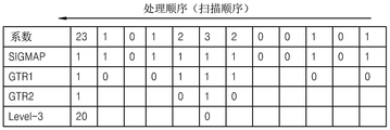
fig. 20 is a table illustrating transform coefficients included in the subsets illustrated in fig. 16 to 19 and transform coefficient information entropy-encoded and entropy-decoded;
FIG. 21a is a block diagram showing the construction of an entropy encoding apparatus according to an embodiment of the present invention;
FIG. 21b is a block diagram illustrating a structure of an entropy decoding apparatus according to an embodiment of the present invention;
FIG. 22 is a block diagram illustrating the structure of a context modeler according to an embodiment of the present invention;
fig. 23 illustrates a plurality of context sets of a transform unit applied to a luminance component and a plurality of contexts included in each context set according to an embodiment of the present invention;
fig. 24 illustrates a plurality of context sets applied to a transform unit of a chrominance component and a plurality of contexts included in each context set according to an embodiment of the present invention;
FIG. 25 is a flowchart illustrating a method of determining a context model for entropy encoding and entropy decoding a transform coefficient level according to an embodiment of the present invention;
FIG. 26 is a detailed flowchart illustrating a method of determining a context model for entropy encoding and entropy decoding a transform coefficient level according to an embodiment of the present invention;
fig. 27a illustrates a context set index ctxset for determining a context set used in entropy-encoding and entropy-decoding a first critical value flag Gtr1 flag and a second critical value flag Gtr2 flag of a significant transform coefficient of a luminance component and a significant transform coefficient of a chrominance component according to an embodiment of the present invention;
FIG. 27b illustrates context offsets used in entropy encoding and entropy decoding the first and second critical value flags Gtr1 and Gtr2 according to an embodiment of the present invention;
fig. 28 illustrates a display context offset index c1 and the table of entropy-encoded or entropy-decoded transform coefficient information of fig. 20, wherein the context offset index c1 is used in entropy-encoding or entropy-decoding transform coefficients included in a subset, according to an embodiment of the present invention;
fig. 29 illustrates a table displaying a context offset index c1 and entropy-encoded or entropy-decoded transform coefficient information, wherein the context offset index c1 is used in entropy-encoding and entropy-decoding transform coefficients included in a subset, according to another embodiment of the present invention.
Best mode for carrying out the invention
According to an aspect of the present invention, there is provided a method of determining a context model for entropy encoding and entropy decoding a transform coefficient level, the method comprising: dividing the transform unit into subsets having a predetermined size and obtaining significant transform coefficients included in each subset, which are not 0; obtaining a context set index for determining a context set used in entropy-encoding and entropy-decoding a first threshold flag among a plurality of context sets including a plurality of contexts, based on color component information of a transform unit, position information of a first subset including significant transform coefficients, and whether or not there is a significant transform coefficient having a value greater than a first threshold in a second subset processed before the first subset, wherein the first threshold flag indicates whether or not the significant transform coefficient has a value greater than the first threshold; obtaining a context offset for determining one context among a plurality of contexts based on a length of previous transform coefficients having consecutive 1 s, wherein the plurality of contexts include a context set used in entropy encoding and entropy decoding a first critical value flag; a context index indicating a context used in entropy-encoding and entropy-decoding the first critical value flag is obtained by using the context set index and the context offset.
According to another aspect of the present invention, there is provided an apparatus for determining a context model for entropy encoding and entropy decoding a transform coefficient level, comprising: a mapping unit dividing the transform unit into subsets having a predetermined size and obtaining significant transform coefficients included in each subset, which are not 0; a context set obtaining unit obtaining a context set index for determining a context set used in entropy encoding and entropy decoding a first threshold flag indicating whether the significant transform coefficient has a value greater than a first threshold, among a plurality of context sets including a plurality of contexts, based on the color component information of the transform unit, position information of a first subset including the significant transform coefficient, and whether the significant transform coefficient having a value greater than the first threshold exists in a second subset processed before the first subset; a context offset obtaining unit obtaining a context offset for determining one context among a plurality of contexts including a context set used in entropy-encoding and entropy-decoding a first critical value flag based on a length of previous transform coefficients having consecutive 1 s; a context determining unit obtaining a context index indicating a context used in entropy-encoding and entropy-decoding the first critical value flag by using the context set index and the context offset.
Detailed Description
Hereinafter, "image" described in various embodiments of the present application may be a concept referring to inclusion of not only still images but also video images.
When various operations are performed on data related to an image, the data related to the image is divided into data groups, and the same operations may be performed on data included in the same data group. In this specification, a data group formed according to a predetermined standard is referred to as a "data unit". Hereinafter, the operation performed on each "data unit" is understood to be performed using data included in the data unit.
Hereinafter, a method and apparatus for encoding and decoding a video, in which syntax elements having a tree structure are encoded or decoded based on coding units having a hierarchical tree structure, according to an embodiment of the present invention will be described with reference to fig. 1 to 13. In addition, the method of entropy encoding and entropy decoding used in encoding and decoding a video described with reference to fig. 1 to 13 will be described in detail with reference to fig. 14 to 29.
Fig. 1 is a block diagram of a video encoding apparatus 100 according to an embodiment of the present invention.
The video encoding apparatus 100 includes a layered encoder 110 and an entropy encoder 120.
The layered encoder 110 may divide a current picture to be encoded in units of predetermined data units to perform encoding on each data unit. In detail, the layered encoder 110 may divide the current picture based on a maximum coding unit, wherein the maximum coding unit is a maximum-sized coding unit. The maximum coding unit according to an embodiment of the present invention may be a data unit having a size of 32 × 32, 64 × 64, 128 × 128, 256 × 256, etc., wherein the shape of the data unit is a square having a width and a length of several powers of 2 and greater than 8.
A coding unit according to an embodiment of the present invention may be characterized by a maximum size and depth. The depth represents the number of times a coding unit is spatially divided from a maximum coding unit, and as the depth deepens, deeper coding units according to the depth may be divided from the maximum coding unit to a minimum coding unit. The depth of the maximum coding unit is the highest depth, and the depth of the minimum coding unit is the lowest depth. Since the size of the coding unit corresponding to each depth is reduced as the depth of the maximum coding unit is deepened, the coding unit corresponding to the higher depth may include a plurality of coding units corresponding to the lower depths.
As described above, the image data of the current picture is divided into maximum coding units according to the maximum size of the coding units, and each maximum coding unit may include deeper coding units divided according to depths. Since the maximum coding unit according to the embodiment of the present invention is divided according to the depth, image data of a spatial domain included in the maximum coding unit may be hierarchically classified according to the depth.
The maximum depth and the maximum size of the coding unit, which limit the number of times the height and width of the maximum coding unit are hierarchically divided, may be predetermined.
The layered encoder 110 encodes at least one split region obtained by splitting a region of a maximum coding unit according to depths, and determines a depth for outputting finally encoded image data according to the at least one split region. In other words, the layered encoder 110 determines the coded depth by encoding image data in deeper coding units according to depths according to the maximum coding unit of the current picture, and selecting a depth having the smallest coding error. The determined coded depth and the encoded image data according to the maximum coding unit are output to the entropy encoder 120.
Encoding image data in the maximum coding unit based on deeper coding units corresponding to at least one depth equal to or less than the maximum depth, and comparing results of encoding the image data based on each of the deeper coding units. After comparing the coding errors of the deeper coding units, the depth having the smallest coding error may be selected. At least one coded depth may be selected for each maximum coding unit.
As the coding units are hierarchically divided according to depths and as the number of coding units increases, the size of the maximum coding unit is divided. In addition, even if the coding units correspond to the same depth in one maximum coding unit, whether to divide each coding unit corresponding to the same depth into lower depths is determined by measuring coding errors of image data of each coding unit, respectively. Accordingly, even if image data is included in one maximum coding unit, the image data is divided into regions according to depths, and coding errors are different according to the regions in one maximum coding unit, and thus coded depths may be different according to the regions in the image data. Accordingly, one or more coded depths may be determined in one maximum coding unit, and image data of the maximum coding unit may be divided according to coding units of at least one coded depth.
Accordingly, the layered encoder 110 may determine the coding units having the tree structure included in the maximum coding unit. The "coding units having a tree structure" according to an embodiment of the present invention includes coding units corresponding to depths determined as coded depths among all deeper coding units included in a maximum coding unit. The coding units having coded depths may be hierarchically determined according to depths in the same region of the maximum coding unit, and the coding units having coded depths may be independently determined in different regions. Similarly, the coded depth in a current region may be determined independently of the coded depth of another region.
The maximum depth according to an embodiment of the present invention is an index related to the number of times the division is performed from the maximum coding unit to the minimum coding unit. The first maximum depth according to an embodiment of the present invention may represent a total number of times the division is performed from the maximum coding unit to the minimum coding unit. The second maximum depth according to an embodiment of the present invention may represent a total number of depth levels from the maximum coding unit to the minimum coding unit. For example, when the depth of the maximum coding unit is 0, the depth of a coding unit divided once for the maximum coding unit may be set to 1, and the depth of a coding unit divided twice for the maximum coding unit may be set to 2. Here, if the minimum coding unit is a coding unit that divides the maximum coding unit four times, there are 5 depth levels of depths 0, 1, 2, 3, and 4, and thus the first maximum depth may be set to 4 and the second maximum depth may be set to 5.
The prediction encoding and the transformation may be performed according to a maximum coding unit. Also according to the maximum coding unit, prediction coding and transformation are performed based on a deeper coding unit according to a depth equal to or less than the maximum depth.
Since the number of deeper coding units increases every time the maximum coding unit is divided according to the depth, encoding including prediction encoding and transformation is performed on all deeper coding units generated as the depth deepens. For convenience of description, in the maximum coding unit, prediction coding and transformation will now be described based on a coding unit of a current depth.
The video encoding apparatus 100 may variously select the size or shape of a data unit for encoding image data. In order to encode image data, operations such as predictive coding, transformation, and entropy coding are performed, and at this time, the same data unit may be used for all operations, or a different data unit may be used for each operation.
For example, the video encoding apparatus 100 may select not only a coding unit for encoding image data but also a data unit different from the coding unit so as to perform predictive encoding on the image data in the coding unit.
In order to perform prediction encoding on the maximum coding unit, prediction encoding may be performed based on coding units corresponding to coded depths (i.e., coding units that are not further divided into coding units corresponding to lower depths). Hereinafter, a coding unit that is not divided any more and becomes a basic unit for prediction coding will now be referred to as a "prediction unit". The partition obtained by dividing the prediction unit may include the prediction unit or a data unit obtained by dividing at least one of a height and a width of the prediction unit.
For example, when a coding unit of 2N × 2N (where N is a positive integer) is no longer divided and becomes a prediction unit of 2N × 2N, the size of the partition may be 2N × 2N, 2N × N, N × 2N, or N × N. Examples of the partition type include a symmetric partition obtained by symmetrically dividing the height or width of the prediction unit, a partition obtained by asymmetrically dividing the height or width of the prediction unit (such as 1: n or n:1), a partition obtained by geometrically dividing the prediction unit, and a partition having an arbitrary shape.
The prediction mode of the prediction unit may be at least one of an intra mode, an inter mode, and a skip mode. For example, the intra mode or the inter mode may be performed on a partition of 2N × 2N, 2N × N, N × 2N, or N × N. In addition, the skip mode may be performed only for the partition of 2N × 2N. Encoding may be independently performed on one prediction unit in the encoding unit, thereby selecting a prediction mode having a minimum encoding error.
The video encoding apparatus 100 may perform transformation on image data in a coding unit based not only on a coding unit used to encode the image data but also on a data unit different from the coding unit.
In order to perform the transformation on the coding unit, the transformation may be performed based on a data unit having a size less than or equal to the coding unit. For example, the data unit for the transform may include a data unit for an intra mode and a data unit for an inter mode.
The data unit used as the basis for the transformation will now be referred to as the "transformation unit". Similar to the coding unit, the transform unit in the coding unit may be recursively divided into regions of smaller sizes so that the transform unit may be independently determined in units of regions. Accordingly, residual data in a coding unit may be divided based on a transform unit having a tree structure according to a transform depth.
A transform depth may also be set in the transform unit, where the transform depth represents the number of times the height and width of the coding unit are divided to obtain the division performed by the transform unit. For example, in a current coding unit of 2N × 2N, the transform depth may be 0 when the size of the transform unit is 2N × 2N, 1 when the size of the transform unit is N × N, and 2 when the size of the transform unit is N/2 × N/2. That is, the transform unit having a tree structure may also be set according to the transform depth.
Encoding information according to a coding unit corresponding to a coded depth requires not only information on the coded depth but also information on information related to prediction coding and transformation. Accordingly, the layered encoder 110 determines not only a coded depth having a minimum coding error but also a partition type in a prediction unit, a prediction mode according to the prediction unit, and a size of a transform unit for transformation.
The coding unit according to the tree structure among the maximum coding units according to an embodiment of the present invention, and the method of determining the partition will be described in detail later with reference to fig. 3 to 12.
The layered encoder 110 may measure an encoding error of a deeper coding unit according to depth by using rate-distortion optimization based on a lagrangian multiplier.
The entropy encoder 120 outputs image data of a maximum coding unit, which is encoded based on at least one coded depth determined by the layered encoder 110, and information on an encoding mode according to the coded depth in a bitstream. The encoded image data may be an encoding result of residual data of the image. The information on the coding mode according to the coded depth may include information on the coded depth, information on a partition type in a prediction unit, prediction mode information, and size information of a transform unit. In particular, as will be described later, the entropy encoder 120 may obtain a context set index indicating one context set among the plurality of context sets based on whether there is a significant transform coefficient having a value greater than a first critical value in color component information of the transform unit, a position of the current subset, and a previous subset, so as to obtain the context offset based on a length of the previous transform coefficient having consecutive 1 s. In addition, the entropy encoder 120 determines a context index ctdldx indicating a context model based on the obtained context set index and the obtained context offset, wherein the context model is to be applied to a first critical value flag Greaterthan1 flag indicating whether a significant transformation coefficient is greater than a first critical value (i.e., 1) and a second critical value flag Greaterthan2 flag indicating whether a significant transformation coefficient is greater than a second critical value (i.e., 2). The operation of determining a context model to be used for entropy encoding of the transform coefficients, which is to be performed by the entropy encoder 120, will be described later.
Information on the coded depth may be defined by using division information according to depth, wherein the division information according to depth indicates whether encoding is performed on coding units of a lower depth than the current depth. If the current depth of the current coding unit is a coded depth, image data in the current coding unit is encoded and output, and thus division information may be defined not to divide the current coding unit to a lower depth. Alternatively, if the current depth of the current coding unit is not the coded depth, encoding is performed on coding units of lower depths, and thus the partition information may be defined to partition the current coding unit to obtain coding units of lower depths.
If the current depth is not the coded depth, encoding is performed on the coding units divided into the coding units of the lower depths. Since at least one coding unit of a lower depth exists in one coding unit of the current depth, encoding is repeatedly performed on each coding unit of the lower depth, and thus encoding can be recursively performed on coding units having the same depth.
Since the coding units having the tree structure are determined for one maximum coding unit and the information on the at least one coding mode is determined for the coding units of the coded depth, the information on the at least one coding mode may be determined for one maximum coding unit. In addition, since image data is hierarchically divided according to depths, the coded depth of image data of a maximum coding unit may be different according to a location, and thus information on the coded depth and a coding mode may be set for the image data.
Accordingly, the entropy encoder 120 may allocate encoding information regarding the corresponding coded depth and encoding mode to at least one of a coding unit, a prediction unit, and a minimum unit included in the maximum coding unit.
The minimum unit according to an embodiment of the present invention is a square data unit obtained by dividing the minimum coding unit constituting the lowest depth into 4. Alternatively, the minimum unit may be a maximum square data unit among all coding units, prediction units, partition units, and transform units included in the maximum coding unit.
For example, the encoding information output by the entropy encoder 120 may be classified into encoding information of a deeper coding unit according to depth and encoding information according to a prediction unit. The encoding information of the deeper coding unit according to the depth may include information on a prediction mode and information on a partition size. The encoding information according to the prediction unit may include information on an estimated direction of the inter mode, information on a reference picture index of the inter mode, information on a motion vector, information on a chrominance component of the intra mode, and information on an interpolation method of the intra mode. Also, information on a maximum size of a coding unit and information on a maximum depth defined according to a picture, slice, or GOP may be inserted into a header of a bitstream.
In the video encoding apparatus 100, the deeper coding unit may be a coding unit obtained by dividing the height or width of a coding unit of a higher depth (a higher layer) into two. In other words, when the size of the coding unit of the current depth is 2N × 2N, the size of the coding unit of the lower depth is N × N. In addition, the coding unit of the current depth having the size of 2N × 2N may include coding units of up to 4 lower depths.
Accordingly, the video encoding apparatus 100 may form coding units having a tree structure by determining coding units having an optimal shape and an optimal size for each maximum coding unit based on the size and the maximum depth of the maximum coding unit determined in consideration of the characteristics of the current picture. In addition, since encoding can be performed for each maximum coding unit by using any one of various prediction modes and transforms, an optimal encoding mode can be determined in consideration of characteristics of coding units of various image sizes.
Therefore, if an image having a high resolution or a large data amount is encoded in a conventional macroblock, the number of macroblocks per picture is extremely increased. Therefore, the number of pieces of compressed information generated for each macroblock increases, so it is difficult to transmit compressed information, and data compression efficiency is reduced. Accordingly, by using the video encoding apparatus 100, since the encoding unit is adjusted based on the characteristics of the image while increasing the maximum size of the encoding unit in consideration of the size of the image, image compression efficiency can be increased.
Fig. 2 is a block diagram of a video decoding apparatus 200 according to an embodiment of the present invention.
The video decoding apparatus 200 includes a syntax element extraction unit 210, an entropy decoder 220, and a layered decoder 230. Definitions of various terms (such as coding unit, depth, prediction unit, transform unit, and information regarding various encoding modes) used for the decoding operation of the video decoding apparatus 200 are the same as those described with reference to fig. 1 and the video encoding apparatus 100.
The syntax element extraction unit 210 receives and parses a bitstream of the encoded video. The entropy decoder 220 extracts encoded image data for each coding unit having a tree structure according to each maximum coding unit from the parsed bitstream, and outputs the extracted image data to the hierarchical decoder 230.
In addition, the entropy decoder 220 extracts information on a coded depth, a coding mode, color component information, prediction mode information, and the like of the coding unit having the tree structure from the parsed bitstream according to each maximum coding unit. The extracted information on the coded depth and the coding mode is output to the layered decoder 230. The image data in the bitstream is divided into maximum coding units such that the layered decoder 230 can decode the image data for each maximum coding unit.
Information on a coded depth and a coding mode according to a maximum coding unit may be set for information on at least one coding unit corresponding to the coded depth, and the information on the coding mode may include information on a partition type of a corresponding coding unit corresponding to the coded depth, information on a prediction mode, and information on a size of a transform unit. In addition, the division information according to the depth may be extracted as information on the coded depth.
The information regarding the coded depth and the coding mode according to each maximum coding unit extracted by the entropy decoder 220 is information regarding the coded depth and the coding mode determined to generate the minimum coding error when encoding is repeatedly performed on each deeper coding unit according to the depth at an encoding side, such as the video encoding apparatus 100, according to the maximum coding unit. Accordingly, the video decoding apparatus 200 may restore an image by decoding image data according to a coded depth and a coding mode that generate a minimum coding error.
Since encoding information regarding the coded depth and the encoding mode may be allocated to predetermined data units among the corresponding coding unit, prediction unit, and minimum unit, the entropy decoder 220 may extract information regarding the coded depth and the encoding mode according to the predetermined data units. The predetermined data unit to which the same information on the coded depth and the coding mode is allocated may be inferred as being a data unit included in the same maximum coding unit.
Further, as will be described later, the entropy decoder 220 may obtain a context set index indicating one context set among the plurality of context sets based on whether there is a significant transform coefficient having a value greater than a first critical value in color component information of the transform unit, a position of the current subset, and a previous subset, so as to obtain the context offset based on a length of the previous transform coefficient having consecutive 1 s. In addition, the entropy decoder 220 determines a context index ctdldx indicating a context model based on the obtained context set index and the obtained context offset, wherein the context model is to be applied to a first critical value flag Greaterthan1 flag indicating whether a significant transform coefficient is greater than a first critical value (i.e., 1) and a second critical value flag Greaterthan2 flag indicating whether a significant transform coefficient is greater than a second critical value (i.e., 2).
The hierarchical decoder 230 restores the current picture by decoding the image data in each maximum coding unit based on the information on the coded depth and the coding mode according to the maximum coding unit. In other words, the hierarchical decoder 230 may decode the encoded image data based on the extracted information on the partition type, the prediction mode, and the transform unit of each coding unit among the coding units having the tree structure included in each maximum coding unit. The decoding process may include prediction (including intra prediction and motion compensation) and inverse transform.
The hierarchical decoder 230 may perform intra prediction or motion compensation according to a partition and a prediction mode of each coding unit based on information about a partition type and a prediction mode of a prediction unit of a coding unit according to a coded depth.
Also, the hierarchical decoder 230 may perform inverse transformation according to each transform unit in the coding unit based on the information regarding the size of the transform unit of the coding unit according to the coded depth, so as to perform inverse transformation according to the maximum coding unit.
The hierarchical decoder 230 may determine at least one coded depth of a current maximum coding unit by using division information according to depths. The current depth is a coded depth if the partition information indicates that the image data is no longer partitioned in the current depth. Accordingly, the hierarchical decoder 230 may decode a coding unit of a current depth with respect to image data of a current maximum coding unit by using information on a partition type of a prediction unit, information on a prediction mode, and information on a size of a transform unit.
In other words, a data unit containing coding information including the same partition information may be collected by observing a set of coding information allocated to a predetermined data unit among a coding unit, a prediction unit, and a minimum unit, and the collected data unit may be regarded as one data unit to be decoded in the same coding mode by the layered decoder 230.
The video decoding apparatus 200 may obtain information on at least one coding unit that generates a minimum coding error when encoding is recursively performed for each maximum coding unit, and may decode the current picture using the information. In other words, encoded image data of coding units having a tree structure, which are determined as the optimal coding units among the maximum coding units, may be decoded.
Accordingly, even if image data has high resolution and a large data amount, the image data can be efficiently decoded and restored by using the size of a coding unit and a coding mode, which are adaptively determined according to the characteristics of the image data by using information about an optimal coding mode received from an encoder.
A method of determining a coding unit, a prediction unit, and a transform unit having a tree structure according to an embodiment of the present invention will now be described with reference to fig. 3 to 13.
Fig. 3 is a diagram for describing a concept of a coding unit according to an embodiment of the present invention.
The size of the coding unit may be expressed as width × height, and may be 64 × 64, 32 × 32, 16 × 16, and 8 × 8. A 64 × 64 coding unit may be divided into 64 × 64, 64 × 32, 32 × 64, or 32 × 32 partitions, a 32 × 32 coding unit may be divided into 32 × 32, 32 × 16, 16 × 32, or 16 × 16 partitions, a 16 × 16 coding unit may be divided into 16 × 16, 16 × 8, 8 × 16, or 8 × 8 partitions, and an 8 × 8 coding unit may be divided into 8 × 8, 8 × 4, 4 × 8, or 4 × 4 partitions.
In the video data 310, the resolution is 1920 × 1080, the maximum size of a coding unit is 64, and the maximum depth is 2. In the video data 320, the resolution is 1920 × 1080, the maximum size of a coding unit is 64, and the maximum depth is 3. In the video data 330, the resolution is 352 × 288, the maximum size of a coding unit is 16, and the maximum depth is 1. The maximum depth shown in fig. 3 represents the total number of divisions from the maximum coding unit to the minimum coding unit.
If the resolution is high or the data amount is large, the maximum size of the coding unit may be large, thereby not only improving the coding efficiency but also accurately reflecting the features of the image. Accordingly, the maximum size of the coding unit of the video data 310 and 320 having a higher resolution than the video data 330 may be 64.
Since the maximum depth of the video data 310 is 2, since the depth is deepened to two layers by dividing the maximum coding unit twice, the coding units 315 of the video data 310 may include a maximum coding unit having a long axis size of 64 and coding units having long axis sizes of 32 and 16. Meanwhile, since the maximum depth of the video data 330 is 1, since the depth is deepened to one layer by dividing the maximum coding unit once, the coding units 335 of the video data 330 may include a maximum coding unit having a long axis size of 16 and a coding unit having a long axis size of 8.
Since the maximum depth of the video data 320 is 3, since the depth is deepened to 3 layers by dividing the maximum coding unit three times, the coding units 325 of the video data 320 may include the maximum coding unit having a long axis size of 64 and coding units having long axis sizes of 32, 16, and 8. As the depth deepens, the detailed information can be accurately represented.
Fig. 4 is a block diagram of a video encoder 400 based on coding units having a hierarchical structure according to an embodiment of the present invention.
The intra predictor 410 performs intra prediction on coding units in an intra mode for the current frame 405, and the motion estimator 420 and the motion compensator 425 perform inter estimation and motion compensation on coding units in an inter mode by using the current frame 405 and the reference frame 495, respectively.
The data output from the intra predictor 410, the motion estimator 420, and the motion compensator 425 are output as quantized transform coefficients through the transformer 430 and the quantizer 440. The quantized transform coefficients are restored into data in a spatial domain through the inverse quantizer 460 and the inverse transformer 470, and the restored data in the spatial domain is output as a reference frame 495 after being post-processed through the deblocking unit 480 and the loop filtering unit 490. The quantized transform coefficients may be output as a bitstream 455 by an entropy encoder 450.
When encoding a syntax element of a transform unit, such as a first critical value flag Gtr1 flag or a second critical value flag Gtr2 flag, the entropy encoder 450 obtains a context set index based on whether there are significant transform coefficients having a value greater than the first critical value, a position of a current subset, and a previous subset in color component information of the transform unit, obtains a context offset based on a length of previous transform coefficients having consecutive 1 s, and determines a context index indicating a context model based on the obtained context set index and the obtained context offset.
In order to apply the image encoder 400 to the video encoding apparatus 100, all elements of the image encoder 400 (i.e., the intra predictor 410, the motion estimator 420, the motion compensator 425, the transformer 430, the quantizer 440, the entropy encoder 450, the inverse quantizer 460, the inverse transformer 470, the deblocking unit 480, and the loop filtering unit 490) perform an operation based on each of the coding units having a tree structure while considering a maximum depth of each maximum coding unit.
Specifically, the intra predictor 410, the motion estimator 420, and the motion compensator 425 determine a partition and a prediction mode of each of the coding units having a tree structure while considering the maximum size and the maximum depth of the current maximum coding unit, and the transformer 430 determines the size of the transformation unit in each of the coding units having a tree structure.
Fig. 5 is a block diagram of a coding unit-based video decoder 500 according to an embodiment of the present invention.
The parser 510 parses encoded image data to be decoded and encoding information required for decoding from the bitstream 505. The encoded image data is output as inverse quantized data through the entropy decoder 520 and the inverse quantizer 530, and the inverse quantized data is restored as image data in a spatial domain through the inverse transformer 540.
For image data in a spatial domain, the intra predictor 550 performs intra prediction on a coding unit in an intra mode, and the motion compensator 560 performs motion compensation on the coding unit in an inter mode by using the reference frame 585.
The image data in the spatial domain passed through the intra predictor 550 and the motion compensator 560 may be output as a restored frame 595 after being post-processed through the deblocking unit 570 and the loop filtering unit 580. In addition, the image data post-processed through the deblocking unit 570 and the loop filtering unit 580 may be output as a reference frame 585.
In order to apply the image decoder 500 to the video decoding apparatus 200, all elements of the image decoder 500 (i.e., the parser 510, the entropy decoder 520, the inverse quantizer 530, the inverse transformer 540, the intra predictor 550, the motion compensator 560, the deblocking unit 570, and the loop filtering unit 580) perform an operation based on coding units having a tree structure for each maximum coding unit.
The intra predictor 550 and the motion compensator 560 determine partitions and prediction modes of each coding unit having a tree structure, and the inverse transformer 540 must determine the size of a transform unit of each coding unit. Also, when decoding a syntax element of the transform unit, such as the first critical value flag Gtr1 flag or the second critical value flag Gtr2 flag, the entropy decoder 520 obtains a context set index based on whether there are significant transform coefficients having a value greater than the first critical value, a position of the current subset, and a previous subset in the color component information of the transform unit, obtains a context offset based on a length of the previous transform coefficients having consecutive 1 s, and determines a context index indicating a context model based on the obtained context index and the obtained context offset.
Fig. 6 is a diagram illustrating a deeper coding unit according to depth and a partition according to an embodiment of the present invention.
The video encoding apparatus 100 and the video decoding apparatus 200 use layered coding units to consider the characteristics of images. The maximum height, the maximum width, and the maximum depth of the coding unit may be adaptively determined according to the characteristics of the image, or may be set differently by a user. The size of the deeper coding unit according to the depth may be determined according to a predetermined maximum size of the coding unit.
In the hierarchical structure 600 of coding units according to an embodiment of the present invention, the maximum height and the maximum width of a coding unit are both 64, and the maximum depth is 4. Since the depth deepens along the vertical axis of the hierarchical structure 600, both the height and the width of the deeper coding units are divided. In addition, prediction units and partitions are shown along the horizontal axis of the hierarchy 600, where the prediction units and partitions are the basis for predictive coding each of the deeper coding units.
In other words, in the hierarchical structure 600, the coding unit 610 is a maximum coding unit in which the depth is 0 and the size (i.e., height multiplied by width) is 64 × 64. As the depth deepens along the vertical axis, there are a coding unit 620 of size 32 × 32 and depth 1, a coding unit 630 of size 16 × 16 and depth 2, a coding unit 640 of size 8 × 8 and depth 3, and a coding unit 650 of size 4 × 4 and depth 4. The coding unit 650 having a size of 4 × 4 and a depth of 4 is a minimum coding unit.
The prediction unit and the partition of the coding unit are arranged along a horizontal axis according to each depth. In other words, if the coding unit 610 having the size of 64 × 64 and the depth of 0 is a prediction unit, the prediction unit may be divided into partitions included in the coding unit 610, i.e., a partition 610 having the size of 64 × 64, a partition 612 having the size of 64 × 32, a partition 614 having the size of 32 × 64, or a partition 616 having the size of 32 × 32.
Similarly, a prediction unit of the coding unit 620 having the size of 32 × 32 and the depth of 1 may be divided into partitions included in the coding unit 620, i.e., a partition 620 having the size of 32 × 32, a partition 622 having the size of 32 × 16, a partition 624 having the size of 16 × 32, and a partition 626 having the size of 16 × 16.
Similarly, the prediction unit of the coding unit 630 having the size of 16 × 16 and the depth of 2 may be divided into partitions included in the coding unit 630, i.e., a partition 630 having a size of 16 × 16, a partition 632 having a size of 16 × 8, a partition 634 having a size of 8 × 16, and a partition 636 having a size of 8 × 8 included in the coding unit 630.
Similarly, a prediction unit of the coding unit 640 having a size of 8 × 8 and a depth of 3 may be divided into partitions included in the coding unit 640, i.e., a partition having a size of 8 × 8, partitions 642 having a size of 8 × 4, partitions 644 having a size of 4 × 8, and partitions 646 having a size of 4 × 4 included in the coding unit 640.
The coding unit 650 having a size of 4 × 4 and a depth of 4 is a minimum coding unit and a coding unit of the lowest depth. The prediction unit of the coding unit 650 is allocated only to the partition having the size of 4 × 4.
In order to determine at least one coded depth of the coding units constituting the maximum coding unit 610, the coding unit determiner 120 of the video encoding apparatus 100 performs encoding on the coding unit corresponding to each depth included in the maximum coding unit 610.
As the depth deepens, the number of deeper coding units according to depth, which include data having the same range and the same size, increases. For example, four coding units corresponding to depth 2 are required to cover data included in one coding unit corresponding to depth 1. Therefore, in order to code the same data according to the depth comparison, a coding unit corresponding to depth 1 and four coding units corresponding to depth 2 are coded.
In order to perform encoding for a current depth among depths, a minimum encoding error may be selected for the current depth by performing encoding for each prediction unit in a coding unit corresponding to the current depth along a horizontal axis of the hierarchical structure 600. Alternatively, as the depth deepens along the vertical axis of the hierarchical structure 600, the minimum coding error may be searched for by comparing the minimum coding error according to the depth by performing coding for each depth. The depth and the partition having the smallest coding error in the coding unit 610 may be selected as the coded depth and the partition type of the coding unit 610.
Fig. 7 is a diagram for describing a relationship between an encoding unit 710 and a transformation unit 720 according to an embodiment of the present invention.
The video encoding apparatus 100 or the video decoding apparatus 200 encodes or decodes an image according to a coding unit having a size smaller than or equal to the maximum coding unit for each maximum coding unit. The size of a transform unit for transformation during encoding may be selected based on a data unit that is not larger than a corresponding coding unit.
For example, in the video encoding apparatus 100 or the video decoding apparatus 200, if the size of the coding unit 710 is 64 × 64, the transform may be performed by using the transform unit 720 having the size of 32 × 32.
Also, data of the coding unit 710 having the size of 64 × 64 may be encoded by performing a transform on each of the transform units having the sizes of 32 × 32, 16 × 16, 8 × 8, and 4 × 4 smaller than 64 × 64, and then a transform unit having the smallest coding error may be selected.
Fig. 8 is a diagram for describing coding information of a coding unit corresponding to a coded depth according to an embodiment of the present invention.
The output unit 130 of the video encoding apparatus 100 may encode information 800 regarding a partition type, information 810 regarding a prediction mode, and information 820 regarding a transform unit size of each coding unit corresponding to a coded depth, and transmit the information 800, the information 810, and the information 820 as information regarding a coding mode.
The information 800 indicates information on the shape of a partition obtained by dividing a prediction unit of a current coding unit, wherein the partition is a data unit used for prediction coding of the current coding unit. For example, the current coding unit CU _0 of size 2N × 2N may be divided into any one of the following partitions: a partition 802 of size 2N × 2N, a partition 804 of size 2N × N, a partition 806 of size N × 2N, and a partition 808 of size N × N. Here, the information on the partition type 800 is set to indicate one of a partition 804 of a size of 2N × N, a partition 806 of a size of N × 2N, and a partition 808 of a size of N × N.
The information 810 indicates a prediction mode of each partition. For example, the information 810 may indicate a mode of predictive coding performed on the partition indicated by the information 800, i.e., an intra mode 812, an inter mode 814, or a skip mode 816.
The information 820 indicates a transform unit on which a transform is based when performing a transform on the current coding unit. For example, the transform unit may be the first intra transform unit 822, the second intra transform unit 824, the first inter transform unit 826, or the second intra transform unit 828.
The entropy decoder 220 of the video decoding apparatus 200 may extract and use the information 800, 810, and 820 for decoding according to each of the deeper coding units.
Fig. 9 is a diagram of a deeper coding unit according to depth according to an embodiment of the present invention.
The partitioning information may be used to indicate a change in depth. The partition information indicates whether the coding unit of the current depth is partitioned into coding units of lower depths.
The prediction unit 910 for prediction encoding the coding unit 900 having a depth of 0 and a size of 2N _0 × 2N _0 may include partitions of the following partition types: a partition type 912 having a size of 2N _0 × 2N _0, a partition type 914 having a size of 2N _0 × N _0, a partition type 916 having a size of N _0 × 2N _0, and a partition type 918 having a size of N _0 × N _ 0. Fig. 9 shows only partition types 912 to 918 obtained by symmetrically dividing the prediction unit 910, but the partition types are not limited thereto, and the partitions of the prediction unit 910 may include asymmetric partitions, partitions having a predetermined shape, and partitions having a geometric shape.
According to each partition type, prediction encoding is repeatedly performed on one partition having a size of 2N _0 × 2N _0, two partitions having a size of 2N _0 × N _0, two partitions having a size of N _0 × 2N _0, and four partitions having a size of N _0 × N _ 0. The prediction encoding in the intra mode and the inter mode may be performed on partitions having sizes of 2N _0 × 2N _0, 2N _0 × N _0, and N _0 × N _ 0. The prediction encoding in the skip mode may be performed only on partitions having a size of 2N _0 × 2N _ 0.
The prediction unit 910 may not be divided to a lower depth if a coding error is smallest in one of the partition types 912 to 916 having sizes of 2N _0 × 2N _0, 2N _0 × N _0, and N _0 × 2N _ 0.
If the coding error is minimum in the partition type 918 of size N _0 × N _0, the depth is changed from 0 to 1 to divide the partition type 918 in operation 920 and coding is repeatedly performed on the partition type coding unit of depth 2 and size N _0 × N _0 to search for the minimum coding error.
The prediction unit 940 for prediction encoding the (partition type) coding unit 930 having a depth of 1 and a size of 2N _1 × 2N _1(═ N _0 × N _0) may include partitions of the following partition types: a partition type 942 of size 2N _1 × 2N _1, a partition type 944 of size 2N _1 × N _1, a partition type 946 of size N _1 × 2N _1, and a partition type 948 of size N _1 × N _ 1.
If the coding error is minimum in the partition type 948 of size N _1 × N _1, the depth is changed from 1 to 2 to divide the partition type 948 in operation 950, and the coding is repeatedly performed on the coding unit 960 of depth 2 and size N _2 × N _2 to search for the minimum coding error.
When the maximum depth is d, a partitioning operation according to each depth may be performed until the depth becomes d-1, and partitioning information may be encoded until the depth is one of 0 to d-2. In other words, when encoding is performed until the depth is d-1 after the coding unit corresponding to the depth of d-2 is divided in operation 970, the prediction unit 990 for prediction-encoding the coding unit 980 having the depth of d-1 and the size of 2N _ (d-1) × 2N _ (d-1) may include partitions of the following partition types: a partition type 992 of size 2N _ (d-1). times.2N (d-1), a partition type 994 of size 2N _ (d-1). times.N (d-1), a partition type 996 of size N _ (d-1). times.2N (d-1), and a partition type 998 of size N _ (d-1). times.N (d-1).
Predictive encoding may be repeatedly performed on one partition of size 2N _ (d-1) × 2N _ (d-1), two partitions of size 2N _ (d-1) × N _ (d-1), two partitions of size N _ (d-1) × 2N _ (d-1), and four partitions of size N _ (d-1) × N _ (d-1) among the partition types 992 to 998 to search for a partition type having a minimum encoding error.
Even when the partition type 998 of size N (d-1) xN (d-1) has the minimum coding error, since the maximum depth is d, the coding unit CU (d-1) of depth d-1 is not divided to a lower depth any more, the coding depth of the coding unit constituting the current maximum coding unit 900 is determined to be d-1, and the partition type of the current maximum coding unit 900 may be determined to be N (d-1) xN (d-1). Also, since the maximum depth is d, partition information of the coding unit 952 having a depth of d-1 is not set.
The data unit 999 may be the "minimum unit" for the current maximum coding unit. The minimum unit according to an embodiment of the present invention may be a rectangular data unit obtained by dividing the minimum coding unit 980 into 4. By repeatedly performing encoding, the video encoding apparatus 100 may determine a coded depth by selecting a depth having a minimum coding error by comparing coding errors according to depths of the coding unit 900, and set a corresponding partition type and a prediction mode as a coding mode of the coded depth.
In this way, the minimum coding errors according to depths are compared in all depths 1 to d, and the depth having the minimum coding error may be determined as a coded depth. The coded depth, the partition type of the prediction unit, and the prediction mode may be encoded and transmitted as information on the encoding mode. In addition, since the coding unit is divided from a depth of 0 to a coded depth, only the division information of the coded depth is set to 0, and the division information of depths other than the coded depth is set to 1.
The entropy decoder 220 of the video decoding apparatus 200 may extract and use information about the coded depth and the prediction unit of the coding unit 900 to decode the coding unit 912. The video decoding apparatus 200 may perform decoding by determining a depth, of which division information is 0, as a coded depth using division information according to depths, and using information regarding a coding mode of the corresponding depth.
Fig. 10 to 12 are diagrams for describing a relationship between an encoding unit 1010, a prediction unit 1060, and a transform unit 1070 according to an embodiment of the present invention.
The coding unit 1010 is a coding unit having a tree structure corresponding to the coded depth determined by the video encoding apparatus 100 among the maximum coding units. The prediction unit 1060 is a partition of the prediction unit in each coding unit 1010, and the transform unit 1070 is a transform unit of each coding unit 1010.
When the depth of the maximum coding unit is 0 in the coding unit 1010, the depths of the coding units 1012 and 1054 are 1, the depths of the coding units 1014, 1016, 1018, 1028, 1050, and 1052 are 2, the depths of the coding units 1020, 1022, 1024, 1026, 1030, 1032, and 1048 are 3, and the depths of the coding units 1040, 1042, 1044, and 1046 are 4.
In the prediction unit 1060, some coding units 1014, 1016, 1022, 1032, 1048, 1050, 1052, and 1054 are obtained by dividing coding units. In other words, the size of the partition type in the coding units 1014, 1022, 1050, and 1054 is 2N × N, the size of the partition type in the coding units 1016, 1048, and 1052 is N × 2N, and the size of the partition type of the coding unit 1032 is N × N. The prediction unit and partition of the coding unit 1010 are less than or equal to each coding unit.
In the transform unit 1070 in a data unit smaller than the encoding unit 1052, a transform or inverse transform is performed on the image data of the encoding unit 1052. In addition, the coding units 1014, 1016, 1022, 1032, 1048, 1050, 1052, and 1054 in the transform unit 1070 are different from the coding units 1014, 1016, 1022, 1032, 1048, 1050, 1052, and 1054 in the prediction unit 1060 in terms of size and shape. In other words, the video encoding apparatus 100 and the video decoding apparatus 200 may independently perform intra prediction, motion estimation, motion compensation, transformation, and inverse transformation on data units in the same coding unit.
Accordingly, encoding is recursively performed on each coding unit having a hierarchical structure in each region of the largest coding unit to determine an optimal coding unit, so that coding units having a recursive tree structure can be obtained. The encoding information may include partition information on the coding unit, information on a partition type, information on a prediction mode, and information on a size of the transform unit. Table 1 shows encoding information that can be set by the video encoding apparatus 100 and the video decoding apparatus 200.
[ Table 1]

The entropy encoder 120 of the video encoding apparatus 100 may output encoding information regarding coding units having a tree structure, and the entropy decoder 220 of the video decoding apparatus 200 may extract the encoding information regarding the coding units having the tree structure from the received bitstream.
The partition information indicates whether to partition the current coding unit into coding units of lower depths. If the partition information of the current depth d is 0, a depth at which the current coding unit is no longer partitioned into lower depths is a coded depth, so that information on a partition type, a prediction mode, and a size of a transform unit may be defined for the coded depth. If the current coding unit is further divided according to the division information, encoding is independently performed on four divided coding units of lower depths.
The prediction mode may be one of an intra mode, an inter mode, and a skip mode. Intra and inter modes may be defined for all partition types, with skip modes defined only for partition types of size 2N × 2N.
The information on the partition type may indicate symmetric partition types having sizes of 2N × 2N, 2N × N, N × 2N, and N × N obtained by symmetrically dividing the height or width of the prediction unit, and asymmetric partition types having sizes of 2N × nU, 2N × nD, nL × 2N, and nR × 2N obtained by asymmetrically dividing the height or width of the prediction unit. The asymmetric partition types of sizes of 2 nxnu and 2 nxnd may be obtained by dividing the height of the prediction unit by 1: N and N:1 (where N is an integer greater than 1), respectively, and the asymmetric partition types of sizes nL × 2N and nR × 2N may be obtained by dividing the width of the prediction unit by 1: N and N:1, respectively.
The size of the transform unit may be set to two types in intra mode and two types in inter mode. In other words, if the partition information of the transform unit is 0, the size of the transform unit may be 2N × 2N, i.e., the size of the current coding unit. If the partition information of the transform unit is 1, the transform unit may be obtained by partitioning the current coding unit. In addition, the size of the transform unit may be N × N if the partition type of the current coding unit having the size of 2N × 2N is a symmetric partition type, and N/2 × N/2 if the partition type of the current coding unit is an asymmetric partition type.
The encoding information regarding the coding units having the tree structure may include at least one of a coding unit, a prediction unit, and a minimum unit corresponding to the coded depth. The coding unit corresponding to the coded depth may include at least one of a prediction unit and a minimum unit including the same coding information.
Accordingly, whether the neighboring data units are included in the same coding unit corresponding to the coded depth is determined by comparing the coding information of the neighboring data units. In addition, a corresponding coding unit corresponding to the coded depth is determined by using the coding information of the data unit, and thus the distribution of coded depths in the maximum coding unit may be determined.
Accordingly, if the current coding unit is predicted based on the encoding information of the neighboring data units, the encoding information of data units in deeper coding units neighboring the current coding unit may be directly referred to and used.
Alternatively, if the current coding unit is predicted based on the encoding information of the neighboring data units, the data units neighboring the current coding unit are searched using the encoding information of the data units, and the searched neighboring coding units may be referred to predict the current coding unit.
Fig. 13 is a diagram for describing a relationship among a coding unit, a prediction unit, and a transform unit according to the coding mode information of table 1.
The maximum coding unit 1300 includes coding units 1302, 1304, 1306, 1312, 1314, 1316, and 1318 of coded depths. Here, since the coding unit 1318 is a coding unit of coded depth, the partition information may be set to 0. The information on the partition type of the coding unit 1318 having a size of 2N × 2N may be set to one of the following partition types: a partition type 1322 of size 2N × 2N, a partition type 1324 of size 2N × N, a partition type 1326 of size N × 2N, a partition type 1328 of size N × N, a partition type 1332 of size 2N × nU, a partition type 1334 of size 2N × nD, a partition type 1336 of size nL × 2N, and a partition type 1338 of size nR × 2N.
When the partition type is set to be symmetrical (i.e., partition type 1322, 1324, 1326, or 1328), if the partition information (TU size flag) of the transform unit is 0, the transform unit 1342 of size 2N × 2N is set, and if the TU size flag is 1, the transform unit 1344 of size N × N is set.
When the partition type is set to be asymmetric (e.g., partition type 1332, 1334, 1336, or 1338), a transform unit 1352 of size 2N × 2N is set if the TU size flag is 0, and a transform unit 1354 of size N/2 × N/2 is set if the TU size flag is 1.
The TU size flag is the type of transform index; the size of the transform unit corresponding to the transform index may be identified according to a prediction unit type or a partition type of the coding unit.
When the partition type is set to be symmetrical (i.e., partition type 1322, 1324, 1326, or 1328), a transform unit 1342 of size 2N × 2N is set if a TU size flag of the transform unit is 0, and a transform unit 1344 of size N × N is set if the TU size flag is 1.
When the partition type is set to be asymmetric (e.g., partition type 1332(2N × nU), 1334(2N × nD), 1336(nL × 2N), or 1338(nR × 2N)), a transform unit 1352 of size 2N × 2N is set if the TU size flag is 0, and a transform unit 1354 of size N/2 × N/2 is set if the TU size flag is 1.
Referring to fig. 13, the TU size flag described above is a flag having a value of 0 or 1, but the TU size flag is not limited to 1 bit, and the transform unit may be hierarchically divided while the TU size flag is increased from 0. Transform unit partition information (TU size flag) may be used as an example of the transform index.
In this case, when the TU size flag according to the embodiment is used and the maximum size and the minimum size of the transform unit are used, the size of the transform unit actually used may be represented. The video encoding apparatus 100 may encode the maximum transform unit size information, the minimum transform unit size information, and the maximum transform unit partition information. The encoded maximum transform unit size information, minimum transform unit size information, and maximum transform unit partition information may be inserted into a Sequence Parameter Set (SPS). The video decoding apparatus 200 may perform video decoding using the maximum transform unit size information, the minimum transform unit size information, and the maximum transform unit partition information.
For example, (a) if the size of the current coding unit is 64 × 64 and the maximum transform unit size is 32 × 32, (a-1) if the TU size flag is 0, the size of the transform unit is 32 × 32, (a-2) if the TU size flag is 1, the size of the transform unit is 16 × 16, (a-3) if the TU size flag is 2, the size of the transform unit is 8 × 8.
Alternatively, (b) if the size of the current coding unit is 32 × 32 and the size of the minimum transform unit is 32 × 32, (b-1) if the TU size flag is 0, the size of the transform unit is 32 × 32, and since the size of the transform unit cannot be smaller than 32 × 32, no more TU size flag may be set.
Alternatively, (c) if the size of the current coding unit is 64 × 64 and the maximum TU size flag is 1, the TU size flag may be 0 or 1, and other TU size flags may not be set.
Therefore, when a maximum TU size flag is defined as "maxtransformsize index", a minimum TU size flag is defined as "MinTransformSize", and a transform unit (i.e., a basic transform unit RootTu) in the case where the TU size flag is 0 is "RootTuSize", a size "CurrMinTuSize" of a minimum transform unit available in a current coding unit may be defined by equation (1) below. CurrMinTuSize ═ max (MinTransformsize, RootTuSize/(2^ MaxTransformsize) … (1)
The basic transform unit size "RootTuSize", which is the size of the transform unit when the TU size flag is 0, may indicate a maximum transform unit selectable for the system, compared to the size "CurrMinTuSize" of the smallest transform unit available in the current coding unit. That is, according to equation (1), "RootTuSize/(2 ^ maxtransizandex)" is the size of a transform unit obtained by dividing "RootTuSize", which is the size of the transform unit when the transform unit division information is 0, by the division number corresponding to the maximum transform unit division information, "MinTransformSize" is the size of the minimum transform unit, and thus the smaller value of "RootTuSize/(2 ^ maxtransizandex)" and "MinTransformSize" may be the size of the minimum transform unit available in the current coding unit "CurrMinTuSize".
The size of the basic transformation unit "RootTuSize" according to an embodiment of the present invention may be different according to a prediction mode.
For example, if the current prediction mode is an inter mode, "RootTuSize" may be determined according to equation (2) below. In equation (2), "MaxTransformSize" refers to the maximum transform unit size, and "PUSize" refers to the current prediction unit size.
RootTuSize=min(MaxTransformSize,PUSize)……(2)
In other words, if the current prediction mode is the inter mode, the size of the basic transform unit size "RootTuSize", which is a transform unit when the TU size flag is 0, may be set to the smaller value of the maximum transform unit size and the current prediction unit size.
If the prediction mode of the current partition unit is the intra mode, "RootTuSize" may be determined according to equation (3) below. "PartitionSize" refers to the size of the current partition unit.
RootTuSize=min(MaxTransformSize,PartitionSize)……(3)
In other words, if the current prediction mode is the intra mode, the basic transform unit size "RootTuSize" may be set to a smaller value among the maximum transform unit size and the current partition unit size.
However, it should be noted that the size of the basic transform unit size "RootTuSize", which is the current maximum transform unit size according to an embodiment of the present invention and is different according to the prediction mode of the partition unit, is an example, and the factor for determining the current maximum transform unit size is not limited thereto.
Hereinafter, an entropy encoding operation of a syntax element performed in the entropy encoder 120 of the video encoding apparatus 100 of fig. 1 and an entropy decoding operation of a syntax element performed in the entropy decoder 220 of the video decoding apparatus 200 of fig. 2 will be described in detail.
As described above, the video encoding apparatus 100 and the video decoding apparatus 200 perform encoding and decoding by dividing a maximum coding unit into coding units smaller than or equal to the maximum coding unit. Prediction units and transform units used in prediction and transform may be determined based on the loss independently of other data units. Since the optimal coding unit can be determined by iteratively encoding each coding unit having a hierarchical structure included in the maximum coding unit, a data unit having a tree structure can be constructed. In other words, for each maximum coding unit, a coding unit having a tree structure, and a prediction unit and a transform unit each having a tree structure may be constructed. For decoding, hierarchical information, which is structure information indicating data units having a hierarchical structure, and non-hierarchical information for decoding other than the hierarchical information need to be transmitted.
As described above with reference to fig. 10 to 12, the information on the hierarchical structure is information required to determine a coding unit having a tree structure, a prediction unit having a tree structure, and a transform unit having a tree structure, and may include a transform unit division flag (TU size flag) indicating the size of the maximum coding unit, a coding depth, partition information of the prediction unit, a division flag indicating whether the coding unit is divided, size information of the transform unit, and a transform unit division flag (TU size flag) indicating whether the transform unit is divided. Examples of the encoding information other than the hierarchical structure information include prediction mode information applied to intra/inter prediction of each prediction unit, motion vector information, prediction direction information, color component information applied to each data unit in the case of using a plurality of color components, and transform coefficient information. Hereinafter, the layer information and the additional layer information may be referred to as a syntax element to be entropy-encoded or entropy-decoded.
In particular, according to an embodiment of the present invention, a method of determining a context model for efficiently entropy-encoding and entropy-decoding a level of a transform coefficient (i.e., size information of a syntax element) is provided. Hereinafter, a method of determining a context model for entropy-encoding and entropy-decoding a level of a transform coefficient will be described in detail.
Fig. 14 is a flowchart illustrating an operation of entropy-encoding and entropy-decoding transform coefficient information included in a transform unit according to an embodiment of the present invention.
Referring to fig. 14, a coded _ block _ flag indicating whether there is a transform coefficient (hereinafter, referred to as a "significant coefficient") other than 0 among transform coefficients included in a current transform unit is first entropy-encoded or entropy-decoded in operation 1410.
If the coded _ block _ flag is 0, only the transform coefficient of 0 exists in the current transform unit, and thus only the value of 0 is entropy-encoded or entropy-decoded into the coded _ block _ flag, and the transform coefficient level information is not entropy-encoded or entropy-decoded.
In operation 1420, if there is a significant coefficient in the current transform unit, a significant map SigMap indicating the position of the significant coefficient is entropy-encoded or entropy-decoded.
The significance map SigMap may be composed of significant bits and predetermined information indicating the last significant coefficient. The significant bit indicates whether the transform coefficient according to each scan index is a significant coefficient or 0, and may be represented by significant _ coeff _ flag [ i ]. As will be described later, the significance map is set in units of subsets having a predetermined size obtained by dividing the transform unit. Accordingly, significant _ coeff _ flag [ i ] indicates whether or not a transform coefficient of the i-th scan index among transform coefficients included in a subset included in a transform unit is 0.
According to the conventional h.264, a flag (End-of-Block) indicating whether each significant coefficient is the last significant coefficient is additionally entropy-encoded or entropy-decoded. However, according to an embodiment of the present invention, the position information of the last significant coefficient itself is entropy-encoded or entropy-decoded. As described above with reference to fig. 1 to 13, the size of the transform unit according to an embodiment of the present invention is not limited to 4 × 4, but may be a larger size such as 8 × 8, 16 × 16, or 32 × 32. Since the size Of the flag (End-Of-Block) indicating whether each significant coefficient is the last significant coefficient increases, it is additionally inefficient to entropy-encode or entropy-decode the flag (End-Of-Block). Therefore, according to an embodiment of the present invention, the position information of the last significant coefficient itself may be entropy-encoded or entropy-decoded. For example, if the position of the last significant coefficient is (x, y), the coordinate value (x, y) may be entropy-encoded or entropy-decoded, where x and y are integers.
Fig. 15 illustrates a subset obtained by dividing a transform unit according to an embodiment of the present invention. Although a 16 × 16 size of the transform unit 1500 is shown in fig. 15, the size of the transform unit 1500 is not limited to 16 × 16, but may be from 4 × 4 to 32 × 32.
Referring to fig. 15, in order to entropy-encode and entropy-decode transform coefficients included in a transform unit 1500, the transform unit 1500 is divided into subsets having a predetermined size. For example, as shown in fig. 15, the transform unit 1500 may be divided into subsets of size 4 × 4. The size of the subset is not limited to 4 × 4, and may be various sizes.
As shown in fig. 15, the transform unit 1500 is divided into 16 subsets, and transform coefficient information is entropy-encoded or entropy-decoded for each subset unit. The transform coefficient information that is entropy-encoded or entropy-decoded may be, for example, a first critical value flag (Greaterthan1 flag, hereinafter referred to as "Gtr 1 flag"), a second critical value flag (Greaterthan2 flag, hereinafter referred to as "Gtr 2 flag"), or level-3, where the Gtr1 flag indicates whether the significant coefficient included in the subset has a value greater than a predetermined first critical value (such as 1), the Gtr2 flag indicates whether the significant coefficient included in the subset has a value greater than a predetermined second critical value (such as 2), and the level-3 indicates a level of the significant coefficient greater than the predetermined second critical value. Here, it is assumed that the first critical value is set to 1 and the second critical value is set to 2, but the first critical value and the second critical value are not limited thereto and may be modified. The first critical value flag (Gtr1 flag) is set only for the transform coefficients of the significance map including 1 (i.e., only for the significant coefficients), and the first critical value flag (Gtr1 flag) is not set for the transform coefficients of 0. In addition, a second critical value flag (Gtr2 flag) is set only for the transform coefficient of which the first critical value flag is 1.
In fig. 15, the subset including the last significant coefficient is assumed to be the subset 111510. The entropy encoding and entropy decoding of the transform coefficient information performed for each subset is performed inversely according to the scan order, starting from the subset 111510 including the last significant coefficient.
Fig. 16 shows a subset 1600 included in the transform unit 1500 of fig. 15, according to an embodiment of the invention.
Referring to fig. 15 and 16, it is assumed that an arbitrary subset included in the transform unit 1500 shown in fig. 15 includes transform coefficients of a size of 4 × 4 as shown in fig. 16. As described above, according to the embodiment of the present invention, the significance map, the first critical value flag Gtr1, and the second critical value flag Gtr2 are entropy-encoded or entropy-decoded in units of subsets.
Fig. 17 shows an active graph SigMap 1700 corresponding to the subset 1600 of fig. 16.
Referring to fig. 16 and 17, an significance map SigMap 1700 having a value of 1 is set for a significant coefficient among transform coefficients having values other than 0 included in the subset 1600 of fig. 16. The significance map SigMap 1700 is entropy-coded or entropy-decoded using a predetermined context model.
Fig. 18 shows a first threshold tab Gtr1 tab 1800 corresponding to the subset 1600 of fig. 16.
Referring to fig. 16 to 18, a first critical value flag Gtr1 flag 1800 indicating whether a corresponding transform coefficient has a value greater than a first critical value (i.e., 1) is set for transform coefficients having a value of 1. If the critical value flag Gtr1 indicates that 1800 is 1, this indicates that the corresponding transform coefficient has a value greater than1, and if the critical value flag Gtr1 indicates that 1800 is 0, this indicates that the corresponding coefficient has a value of 1.
Fig. 19 shows a second threshold marker Gtr2 marker 1900 corresponding to the subset 1600 of fig. 16.
Referring to fig. 16 to 19, a second critical value flag Gtr2 flag 1900 is set only for a transform coefficient of which the first critical value flag Gtr1 flag 1800 is set to 1 among the transform coefficients, the second critical value flag Gtr2 flag 1900 indicating whether the corresponding transform coefficient has a value greater than a second critical value (i.e., 2).
Referring to fig. 19, the level information itself of the transform coefficient of which the second critical value flag Gtr2 flag 1900 is 1 (i.e., the transform coefficients of values 23 and 3 in fig. 16) is entropy-encoded or entropy-decoded. Here, the transform coefficient including the second critical value flag Gtr2 flag 1900 of 1 is a transform coefficient having a value greater than2, and thus, a value (level-3) obtained by subtracting 3 from the level of the corresponding transform coefficient is encoded as level information of the corresponding transform coefficient. In the example described above, when entropy encoding is performed, 20 is encoded without encoding 23, and 0 is encoded as level information and 3 is not encoded as level information. When the entropy decoding is performed, the level information of the transform coefficient is restored by entropy-decoding level-3 of the transform coefficient including the second critical value flag Gtr2 flag 1900 of 1 and then adding 3 to the level-3.
Fig. 20 is a table illustrating transform coefficients included in the subsets illustrated in fig. 16 to 19 and transform coefficient information entropy-encoded or entropy-decoded. As described above, according to the embodiment of the present invention, the significance map SigMap indicating the position and level information of the significance coefficients, the first critical value flag Gtr1, the second critical value flag Gtr2 flag, and the level information (level-3) are entropy-encoded or entropy-decoded according to the predetermined scan order, starting from the last significance coefficient in units of subsets.
Fig. 21a is a block diagram illustrating the structure of an entropy encoding apparatus 2100 according to an embodiment of the present invention. The entropy encoding apparatus 2100 of fig. 21a corresponds to the entropy encoder 120 of the video encoding apparatus 100 of fig. 1.
Referring to fig. 21a, the entropy encoding apparatus 2100 includes a binarizer 2110, a context modeler 2120, and a binary arithmetic encoder 2130. In addition, the binary arithmetic encoder 2130 includes a conventional encoding engine 2132 and a bypass encoding engine 2134.
The syntax element input to the entropy encoding apparatus 2100 may not be a binary value, and thus, if the syntax element is not a binary value, the binarizer 2110 binarizes the syntax element to output a binary (bin) string composed of binary values 0 or 1. bin represents that each bit of the stream consists of 0 or 1 and is coded by adaptive binary arithmetic coding (CABAC). If the syntax element is data including 0 and 1 at the same frequency, the syntax element is output to the bypass coding engine 2134 that does not use the probability value.
The context modeler 2120 provides a probability model for the current coding symbol to the conventional coding engine 2132. In detail, the context modeler 2120 outputs a probability of a binary value used to encode a binary value of a current encoding symbol to the binary arithmetic encoder 2130. When the encoded current syntax element is formed by binarization (i.e., when the encoded current syntax element is formed of binary values), the current encoding symbol refers to each binary value.
The context model is a probability model with respect to the bins, and may include information indicating which of 0 and 1 corresponds to a Maximum Probability Sign (MPS) and a minimum probability sign (LPS), and a probability of the MPS or the LPS. Hereinafter, the context model may be simply referred to as context. Further, a context set refers to a set including a plurality of contexts.
The conventional coding engine 1432 performs binary arithmetic coding on the current coding symbol based on the information on the MPS or LPS and the probability information of the MPS or LPS, which are provided from the context modeler 1420.
As will be described later, in order to determine a context model for entropy-encoding the first critical value Gtr1 flag of the subset, the context modeler 2120 according to an embodiment of the present invention obtains a context set index ctxset for determining a context set used in entropy-encoding the first critical value flag among a plurality of context sets including a plurality of contexts, based on color component information of a transform unit, position information of a subset indicating where the current subset is located in the transform unit, and whether there is a significant coefficient having a value greater than the first critical value in a subset processed before the current subset according to the processing order described above for 15. In addition, the context modeler 2120 obtains a context offset c1 based on the length of previous transform coefficients having consecutive 1 s, wherein the context offset c1 is used to determine one context among a plurality of contexts included in a context set used in entropy encoding the first critical value flag Gtr1 flag. Further, the context modeler 2120 obtains a context index ctxIdx1 indicating a context used in entropy encoding the first critical value flag Gtr1 flag by using the context set index ctxset and the context offset c 1. The value of the context offset c1 is maintained or modified when the first critical value flag Gtr1 flag of the transform unit is frequently entropy-coded or entropy-decoded, and thus the context is always maintained or updated whenever the first critical value flag Gtr1 flag of the transform unit is entropy-coded or entropy-decoded.
Further, the context modeler 2120 obtains a context set index ctxset indicating one of a plurality of context sets used in entropy encoding and entropy decoding the second critical value flag Gtr2, based on the color component information of the transform unit, the position information of the subset indicating where the current subset is located in the transform unit, and whether there is a significant coefficient having a value greater than the first critical value in the subset processed before the current subset according to the processing order described above with respect to fig. 15. The parameter for obtaining the context set index ctsxet used in entropy-encoding and entropy-decoding the second critical value flag Gtr2 flag is the same as the parameter for obtaining the context set index ctxset used in entropy-encoding and entropy-decoding the first critical value flag Gtr1 flag. Thus, when determining a context set for entropy encoding the second critical value token Gtr2 token, the context modeler 2120 may also use the context set index ctxset described above for determining the context set used in entropy encoding the first critical value token. The context offset c2 for determining one of the plurality of contexts included in the context set used in entropy encoding the second critical value flag Gtr2 flag has a value of 0. Accordingly, the context index ctxIdx2 indicating a context used in entropy-encoding the second critical value flag Gtr2 flag is set to be the same as the context set index ctxset of the first critical value flag Gtr1 flag.
Fig. 21b is a block diagram illustrating the structure of an entropy decoding apparatus 2150 according to an embodiment of the present invention. The entropy decoding apparatus 2150 of fig. 21b corresponds to the entropy decoder 220 of the video decoding apparatus 200 of fig. 2. The entropy decoding apparatus 2150 performs the inverse operation of the entropy encoding performed in the entropy encoding apparatus 2100 described above.
Referring to fig. 21b, the entropy decoding apparatus 2150 includes a context modeler 2160, a conventional decoding engine 2170, a bypass decoder 2180, and a binarizer 2190.
The symbols encoded by the bypass encoding are output to the bypass decoder 2180 for decoding, and the symbols encoded by the conventional encoding are decoded by the conventional decoding engine 2170. The conventional decoding engine 2170 arithmetically decodes a binary value of a current encoding symbol based on a context model provided by the context modeler 2160.
The context modeler 2160 determines context models for entropy decoding the first and second critical flags Gtr1, Gtr2 flags in the same manner as the context modeler 2120 of fig. 21a described above. The context modeler 2160 of fig. 21b determines context models for entropy decoding the first and second critical indicia Gtr1, Gtr2 indicia in the same manner as the context modeler 2120 of fig. 21a described above for encoding, except that the context modeler 2160 operates for decoding.
The binarizer 2340 restores the binary string restored in the conventional decoding engine 2170 or the bypass decoder 2180 to the syntax element.
Hereinafter, an operation of determining a context model for entropy-encoding and entropy-decoding the first and second critical value flags Gtr1 and Gtr2, which is performed by using the context modelers 2120 and 2160 of fig. 21a and 21b, will be described in detail.
FIG. 22 is a block diagram illustrating the structure of a context modeler 2200 in accordance with an embodiment of the present invention.
Referring to fig. 22, the context modeler 2200 includes a mapping unit 2210, a context set obtaining unit 2220, a context offset obtaining unit 2230, and a context determining unit 2240.
The mapping unit 2210 obtains position information of significant coefficients included in the current subset that is entropy-encoded or entropy-decoded. When performing entropy encoding, the mapping unit 2210 may obtain the position of the significant coefficient from information of the transform coefficient included in the current subset. When performing entropy decoding, the mapping unit 2210 may obtain the positions of significant coefficients included in the subset from the significant map SigMap.
The context set obtaining unit 2220 obtains a context set index ctxset indicating one of context sets including a plurality of contexts used for entropy encoding and decoding the first and second critical value flags Gtr1 and Gtr2 with respect to the significant coefficient.
In detail, the context set obtaining unit 2220 obtains a context set index for determining a context model used in entropy encoding and entropy decoding the first and second critical value flags Gtr1 and Gtr2, based on the color component information of the transform unit, the location information of the current subset being processed, whether or not there is a significant coefficient having a value greater than the first critical value in the subset processed before the current subset.
The context offset obtaining unit 2230 determines a context offset indicating one context among a plurality of contexts included in the context set. When entropy encoding or entropy decoding is performed on the first critical value flag Gtr1 flag, the context offset c1 may be determined based on the length of a previous transform coefficient having consecutive 1 s before a current significant coefficient being processed when significant coefficients included in a current subset are processed according to a predetermined scan order. The context offset c2 labeled second threshold marker Gtr2 has a value of 0.
The context determining unit 2240 obtains a context index ctxIdx1 by using the context set index ctxset and the context offset c1, wherein the context index ctxIdx1 indicates a context used in entropy encoding or entropy decoding the first critical value flag Gtr1 flag. In order to entropy-encode and entropy-decode the first critical value flag Gtr1, when it is assumed that n context sets (n is an integer) are set and the n context sets have m contexts (m is an integer), a total of n × m contexts may be used in entropy-encoding or entropy-decoding the first critical value flag Gtr1 flag. When it is assumed that a context set index ctxSet indicating one context set of n context sets is an integer from 0 to (n-1), and a context offset c1 indicating one context offset of m context offsets is an integer from 0 to (m-1), a context index ctxIdx1 indicating one context of n × m contexts may be determined based on the following equation: ctxIdx1 ═ ctxSet × m + c 1.
The context index ctxIdx2 indicating one context used in entropy encoding and entropy decoding the second critical value flag Gtr2 flag may be determined based on the following equation: ctxIdx2 ═ ctxSet × 1+ c 2. As described above, since c2 is 0, the context index ctxIdx2 indicating the context used in entropy-encoding and entropy-decoding the second critical value flag Gtr2 flag is determined based on only the value of the set index ctxSet.
Fig. 23 illustrates a plurality of context sets applied to a transform unit of a luminance component and a plurality of contexts included in each context set according to an embodiment of the present invention. Fig. 24 illustrates a plurality of context sets applied to a transform unit of a chrominance component and a plurality of contexts included in each context set according to an embodiment of the present invention.
Referring to fig. 23, in order to entropy-encode and entropy-decode the first critical value flag Gtr1 flag with respect to the transform coefficients included in the luminance component subset, a context included in any one of the first context set 2310, the second context set 2320, the third context set 2330, and the fourth context set 2340 is used. As shown in fig. 23, different contexts included in any one of the four context sets are distinguished by a context offset c1 from 0 to 3. Accordingly, one context among the total 16 contexts marked by the first critical value marker Gtr1 of the transform unit to be applied to the subset of luminance components can be determined by using the context set index ctxset and the context offset c 1. That is, the context index ctxIdx1 can be determined by the following equation: ctxIdx1 ═ ctxSet × 4+ c1, where the context index ctxIdx1 indicates one context of the total of 16 contexts marked by the first critical value marker Gtr1 to be applied to the transform unit of the subset of luminance components.
Similarly, when referring to fig. 24, in order to entropy-encode and entropy-decode the first critical value flag Gtr1 flag for the transform unit included in the chroma component subset, a context included in any one of context sets from the total two context sets (the first context set 2410 and the second context set 2420) is used. As shown in fig. 24, the different contexts included in the context set are distinguished by a context offset c1_ chroma from 0 to 3. As will be described later, the context offset c1_ chroma with respect to the chrominance component may be set in the same manner as the context offset c1 for the luminance component. The context index ctxIdx1_ chroma is determined by the following equation: ctxIdx1_ chroma ═ ctxSet × 4+ c1_ chroma, where the context index ctxIdx1_ chroma indicates one context out of a total of 8 contexts marked by the first critical value Gtr1 to be applied to the transform coefficients included in the subset of the chrominance components.
Fig. 27a illustrates a context set index ctxset for determining a context set used in entropy-encoding and entropy-decoding a significant coefficient of a luminance component and a significant coefficient of a chrominance component, marked with a first critical value marker Gtr1 and a second critical value marker Ctr2, according to an embodiment of the present invention.
Referring to fig. 27a, the context set obtaining unit 2220 obtains a context set index ctxset, which is used to determine a context set used in entropy encoding and entropy decoding the first and second critical value flags Gtr1 and Gtr2, based on the color component information of the transform unit, the position information of the current subset being processed, and whether there is a significant coefficient having a value greater than the first critical value in the subset processed before the current subset.
For example, regarding the transform coefficients included in the transform unit of the luminance component, if there is no significant coefficient having a value greater than1 in the previously processed subset (there is no great t1), and when the first critical value flag of the significant coefficient included in the subset located at the leftmost upper position is entropy-encoded or entropy-decoded, a first context set (ctset-0) is obtained. If there is a significant coefficient (at least one great t1) having a value greater than1 in the previously processed subset, and when the first critical value flag of the significant coefficient included in the subset located at the leftmost upper position (subset 0) is entropy-encoded or entropy-decoded, a second context set (ctxset ═ 1) is obtained. If there is no significant coefficient having a value greater than1 in the previously processed subsets (there is no GtreatT1), and when the first threshold value flag of the significant coefficient included in the subset not located at the upper-left-most position (other subsets) is entropy-encoded or entropy-decoded, a third context set (ctxset ═ 2) is obtained. Further, if there is a significant coefficient (at least one great t1) having a value larger than1 in the previously processed subsets, and when the first critical value flag of the significant coefficient included in the subset not located at the upper-left-most position (other subsets) is entropy-encoded or entropy-decoded, a fourth context set (ctxset ═ 3) is obtained.
With respect to the transform coefficients included in the transform unit of the chrominance component, a context set is obtained based only on whether or not there is a significant coefficient having a value greater than1 in the previously processed subset. In other words, if there is no significant coefficient having a value larger than1 in the previously processed subset (no great t1), a first context set (ctxset ═ 0) is obtained, and if there is a significant coefficient having a value larger than1 in the previously processed subset (at least one great t1), a second context set (ctxset ═ 1) is obtained.
Fig. 27b illustrates context offsets used in entropy encoding and entropy decoding the first and second critical value flags Gtr1 and Gtr2 according to an embodiment of the present invention.
Referring to fig. 27b, in order to determine a context included in a context set used in entropy encoding and entropy decoding the first critical value flag Gtr1 flag, a first context offset (c1 ═ 0) is obtained for a significant coefficient having a value greater than1 among significant coefficients included in the subset. With respect to the significant coefficient processed for the first time among the significant coefficients included in the subset, a second context offset (c1 ═ 1) is obtained. If the length of the previous transform coefficients with consecutive 1's is 1, a third context offset is obtained (c1 ═ 2). If the length of the previous transform coefficients having consecutive 1's is 2 or greater than2, a fourth context offset is obtained (c 1-3). The contextual offset c1 may be applied to the luma component and the chroma components.
The context offset c2 used in entropy encoding and entropy decoding the second critical value flag Gtr2 has a value of 0.
When determining the context set index ctxset and the context offset c1 or c2 for entropy-encoding or entropy-decoding the transform coefficients included in the subset based on the tables of fig. 27a and 27b, the context determining unit 2240 determines the context index ctxIdx1 according to the following equation: ctxIdx1 ═ ctxSet × 4+ c1, where the context index ctxIdx1 indicates one context out of a total of 16 contexts marked by the first critical value markers Gtr1 to be applied to the transform units included in the subset of luminance components. Further, the context determining unit 2240 determines the context index ctxIdx1_ chroma according to the following equation: ctxIdx1_ chroma ═ ctxSet × 4+ c1, where the context index ctxIdx1_ chroma indicates one context of the total of 8 contexts to be applied to the first critical value flag Gtr1 flags of the transform units included in the subset of the chrominance components. Referring to the tables of fig. 27a and 27b, the total number of contexts applied to the first critical value label Gtr1 is 24 (i.e., 16 for the luminance component plus 8 for the 2 × 4 for the chrominance component).
Further, the context determining unit 2240 determines the context index ctxIdx2 according to the following equation: ctxIdx2 ═ ctxset × 1+ c2, where the context index ctxIdx2 indicates the context to be applied to the second critical value flag Gtr2 flag. That is, the context index ctxIdx2 indicating the context to be applied to the second critical value label Gtr2 label is set to the same value as the context set index ctxset. Therefore, referring to the tables of fig. 27a and 27b, the total number of contexts applied to the second critical value label Gtr2 is 8 (i.e., 4 for the luminance component plus 4 for the chrominance component).
Fig. 25 is a flowchart illustrating a method of determining a context model for entropy encoding and entropy decoding a transform coefficient level according to an embodiment of the present invention.
Referring to fig. 25, the mapping unit 2210 divides the transform unit into subsets having predetermined units and obtains significant coefficients included in each subset, which are not 0, in operation 2510. As described above, when performing entropy encoding, the mapping unit 2210 may obtain the position of the significant coefficient from information of the transform coefficient included in the current subset. When performing entropy decoding, the mapping unit 2210 may obtain the positions of significant coefficients included in the subset from the significant map SigMap.
In operation 2520, the context set obtaining unit 2220 obtains a context set index ctxset based on the color component information of the transform unit, the position of the first subset including significant coefficients and being currently processed, and whether significant coefficients greater than a predetermined first critical value exist in the second subset processed before the first subset, wherein the context set index ctxset is used to determine a context set used in entropy encoding and entropy decoding a first critical value flag indicating whether the significant coefficients have a value greater than the first critical value among a plurality of context sets including a plurality of contexts. As shown in fig. 27a and 27b, with respect to the transform coefficients included in the transform unit of the luminance component, the context set obtaining unit 2220 may obtain the context set ctxset indicating one context set among the four context sets depending on whether the position of the first subset is the subset 0 located at the leftmost upper position and whether significant coefficients having a value greater than1 exist in the previously processed subsets. Further, for the transform coefficients included in the transform unit of the chroma component, the context set obtaining unit 2220 may obtain the context set ctxset indicating one of the two context sets based only on whether or not there is a significant coefficient having a value larger than1 in the previously processed subset.
In operation 2530, the context offset obtaining unit 2230 obtains a context offset based on the length of previous transform coefficients having consecutive 1 s, wherein the context offset is used to determine one context among a plurality of contexts included in a context set used in entropy encoding or entropy decoding the first critical value flag Gtr1 flag. As described above, the context offset obtaining unit 2230 may determine the context offset c1 based on the length of consecutive 1's of the previous transform coefficient before the current significant coefficient being processed when the significant coefficients included in the current subset are being processed according to the predetermined scan order. The context offset obtaining unit 2230 may set the context offset c2 used in entropy encoding and entropy decoding the second critical value flag Gtr2 flag to always have a value of 0 without considering other parameters.
In operation 2540, the context determining unit 2240 obtains the context index ctxIdx1 indicating the context used in entropy-encoding and entropy-decoding the first critical value flag Gtr1 flag by using the context set index ctxset and the context offset c 1. As described above, when it is assumed that the context set index ctxSet indicating one of the n context sets is an integer from 0 to (n-1), and the context offset c1 indicating one of the m context offsets is an integer from 0 to (m-1), the context determining unit 2240 may determine the context index ctxIdx1 indicating one of the n × m contexts according to the following equation: ctxIdx1 ═ ctxSet × m + c 1. Further, the context determining unit 2240 may determine the context index ctxIdx2 indicating one context used in entropy-encoding and entropy-decoding the second critical value flag Gtr2 according to the following equation: ctxIdx2 ═ ctxSet × 1+ c 2. Since c2 is 0, the context index ctxIdx2 indicating the context used in entropy encoding and entropy decoding the second critical value flag Gtr2 flag is determined based on only the value of the set index ctxSet.
Fig. 26 is a detailed flowchart illustrating a method of determining a context model for entropy-encoding and entropy-decoding a transform coefficient level according to an embodiment of the present invention.
Referring to fig. 26, in operation 2611, the mapping unit 2210 divides the transform unit into subsets having a predetermined size and obtains significant coefficients included in each subset, which are not 0.
In operation 2612, the context set obtaining unit 2220 determines a context set index ctxset based on the position of the current subset among the parameters used in determining the context set and the color component information. For example, ctxset is set to 0 when the current subset is a subset 0 or a chrominance component located at the upper left most position of the transform unit, and ctxset is set to 2 if the current subset is not a subset located at the upper left most position of the transform unit and is a luminance component.
In operation 2613, the context set obtaining unit 2220 determines whether there is a significant coefficient having a value greater than a first critical value in a previous subset processed just before the current subset. As a result of the determination in operation 2613, if there is a significant coefficient having a value greater than the first critical value in the previous subset, the context set obtaining unit 2220 increases the value of the context set index ctxset set in operation 2612 by 1; otherwise, if there is no significant coefficient having a value greater than the first critical value in the previous subset, the context set obtaining unit 2220 maintains the value of the context set index ctxset set in operation 2612.
In operation 2615, the context offset obtaining unit 2230 sets a value of the context offset c1, where the context offset c1 marks the first critical value flag Gtr1 applied to the significant coefficients of the current subset that is processed for the first time.
In operation 2616, the context determining unit 2240 obtains a context index ctxIdx1 indicating a context to be applied to the first critical value flag Gtr1 flag according to the following equation: ctxIdx1 ═ ctxset × 4+ min (c1, 3). The equation is based on fig. 27a and 27b and determines the length of transform coefficients having consecutive 1 s in operation 2620, and if at least three first critical value marks Gtr1 mark consecutive, the context offset index c1 may have a value equal to 3 or greater than 3. However, referring to fig. 27b, since the context offset index c1 is set to have a value of 2 for at least two consecutive 1 s, min (c1,3) is used to limit the context offset index c1 to not more than 3.
In operation 2617, the conventional encoding engine 2132 and the conventional decoding engine 2170 entropy-encode or entropy-decode the first critical value flag Gtr1 flag based on the context model indicated by the obtained context index ctxIdx 1.
In operation 2618, the context offset obtaining unit 2230 determines whether the first critical value flag Gtr1 flag currently being entropy-encoded or entropy-decoded has a value of 0 and whether the context offset index c1 is 0. The determining operation of operation 2618 is performed to determine the number of consecutive 1 s among the significant coefficients. As a result of the determination in operation 2618, if the currently encoded or decoded first critical value flag Gtr1 has a value of 0 and the context offset index c1 is not 0, the context offset index c1 is increased by 1 in operation 2620. Otherwise, if the currently encoded or decoded first critical value flag Gtr1 flag does not have a value of 0 or the context offset index c1 is 0 as a result of the determination at operation 2618, the context offset index c1 is reset to 0 at operation 2619.
In operations 2621 to 2624, the second critical value flag Gtr2 flag is entropy-coded or entropy-decoded.
At operation 2621, it is determined whether the value of the context offset index c1 is 0. In operation 2622, a context index ctxIdx2 indicating a context to be applied to entropy-encoding or entropy-decoding the second critical value flag Gtr2 flag is set to be the same as a context set index ctxset determined when entropy-encoding or entropy-decoding is performed on the first critical value flag Gtr1 flag.
In operation 2623, the conventional encoding engine 2132 and the conventional decoding engine 2170 entropy-encode or entropy-decode the second critical value marker Gtr2 marker based on the context model indicated by the obtained context index ctxIdx 2.
In operation 2624, the conventional encoding engine 2132 and the conventional decoding engine 2170 entropy-encode or entropy-decode the level of the transform coefficient having a value greater than the second critical value. As described above, the level value (level-3) obtained by subtracting a predetermined value from the corresponding transform coefficient may be entropy-encoded or entropy-decoded.
Fig. 28 illustrates a table including the transform coefficients included in the subset of fig. 20 and a context offset index c1 used in entropy encoding or entropy decoding transform coefficient information that is entropy encoded or entropy decoded, according to an embodiment of the present invention. As described above, the context offset index c1 is determined based on the length of transform coefficients having consecutive values of 1, and it is assumed that the context offset index c1 is obtained according to fig. 27 b. Further, in fig. 28, it is assumed that the order of processing each transform coefficient is from right to left.
Further, here, it is assumed that a context set index ctxset for entropy-encoding and entropy-decoding the first critical value flag Gtr1 and the second critical value flag Gtr2 is determined not based on information on the transform coefficient included in the current subset but based on color component information of the transform unit, the position of the current subset, and whether or not there is a significant coefficient having a value greater than the first critical value in the subset processed before the current subset.
Referring to fig. 28, the last significant coefficient (2810)1 of the preliminarily processed subset is not greater than1, and thus the first critical flag Gtr1 is marked to have a value of 0. Referring to fig. 27b, the context offset c1 labeled with the first critical value label Gtr1 for the primarily processed significant coefficients is set to 1.
Then, the context offset c1 labeled by the first threshold marker Gtr1 for the next significant coefficient with respect to the last significant coefficient (2810) has a value of 2. This is because there was previously a significant coefficient (2810) having a value of 1. Similarly, the context offset c1 labeled first threshold marker Gtr1 for the next significant coefficient 2830 has a value of 3. This is because there were two significant coefficients (2810 and 2820) with two consecutive 1 s in the past.
Since the first threshold marker Gtr1 of the significant transform coefficient (2830) is marked to have a value of 1, the context offset c1 marked by the first threshold marker Gtr1 with respect to all significant coefficients following the significant coefficient (2830) has a value of 0. This is because if the first critical value flag Gtr1 has a value of 1 as a result of the determination of operation 2618 of fig. 26, the context offset c1 is set to 0 according to operation 2619, and thus the context offset c1 with respect to all significant coefficients is set to 0 thereafter.
Fig. 29 illustrates a table including transform coefficients included in a subset and a context offset index c1 used in entropy-encoding or entropy-decoding transform coefficient information that is entropy-encoded or entropy-decoded, according to an embodiment of the present invention. Comparing fig. 28 and 29, fig. 29 is different from fig. 28 in that the last significant coefficient (2910) has a value of 2, and thus the first critical value mark Gtr1 has a value of 1. As described above, the context offset c1 marked with the first critical value Gtr1 with respect to the significant coefficient 2910 being preliminarily processed is set to 1, and the context offset c1 of the first critical value mark Gtr1 with respect to all significant coefficients following the significant coefficient (2910) has a value of 0.
According to the method and apparatus for determining a context model described above, a context set index ctxset is obtained based on color component information of a transform unit, a position of a current subset, and whether there is a significant coefficient having a value greater than a first critical value in a subset processed before the current subset, and a context offset c1 is obtained based on a length of previous transform coefficients having consecutive 1 s.
The criteria for determining the context index or the context offset is not limited to the embodiments of the present invention and may also be modified.
For example, as shown in Table 2, the context offset c1 may be set by grouping cases with similar probabilities.
[ Table 2]

When comparing table 2 with fig. 27b, table 2 shows one continuous transform coefficient and two continuous transform coefficients classified into the same group to be mapped in one context. Further, the context sets may be grouped based on the number of significant coefficients equal to or greater than1 included in the previous subset so as to set the context set index ctxset as shown in table 3.
[ Table 3]


In addition, the context index ctxset may be set as shown in tables 4 to 6 below based on the type of the slice including the current transform unit, the position of the current subset, and the number of transform coefficients having values equal to or greater than a predetermined critical value in the previous subset.
[ Table 4]

Referring to table 4, for example, when transform coefficients included in a subset of transform units included in a slice I are entropy-encoded or entropy-decoded, one of 0 to 5 may be set to a value of a context set index ctxset based on a position of a current subset, whether the number of transform coefficients having a value equal to or greater than a predetermined critical value T1 in a previous subset is 0, 1 to 4, or greater than 4.
[ Table 5]

Referring to table 5, for example, when transform coefficients included in a subset of transform units included in a slice P are entropy-encoded or entropy-decoded, one of 0 to 5 may be set to a value of a context set index ctxset based on a position of a current subset, whether the number of transform coefficients having a value equal to or greater than a predetermined critical value T1 in a previous subset is 0, 1 to 3, or greater than 3.
[ Table 6]

Referring to table 6, for example, when transform coefficients included in a subset of transform units included in a slice B are entropy-encoded or entropy-decoded, one of 0 to 5 may be set to a value of a context set index ctxset based on a position of a current subset, whether the number of transform coefficients having a value equal to or greater than a predetermined critical value T1 in a previous subset is 0, 1, or 2, or greater than 2.
The embodiments of the present invention can be written as computer programs and can be implemented in general-use digital computers that execute the programs using a computer readable recording medium. Examples of the computer readable recording medium include magnetic storage media (e.g., ROM, floppy disks, hard disks, etc.) and optical recording media (e.g., CD-ROMs, or DVDs).
While the present invention has been particularly shown and described with reference to exemplary embodiments thereof, it will be understood by those of ordinary skill in the art that various changes in form and details may be made therein without departing from the spirit and scope of the present invention as defined by the following claims.
Claims (3)
1. An apparatus for determining a context model for entropy decoding a transform coefficient level, the apparatus comprising:
a mapping unit configured to divide the transformation unit into subsets having a predetermined size;
a context set obtaining unit configured to obtain a context set index used in entropy decoding a first critical value flag indicating whether or not a significant transform coefficient contained in a current subset has a value greater than a first critical value;
a context offset obtaining unit configured to obtain a context offset used in entropy-decoding a first critical value flag based on the number of consecutive transform coefficients having a value of 1 among transform coefficients processed before the significant transform coefficient;
a context determining unit configured to obtain a context index indicating a context used in entropy-decoding the first critical value flag by using the context set index and the context offset;
wherein the context set obtaining unit is configured to obtain a context set index used in entropy decoding a second critical value flag indicating whether the significant transform coefficient has a value greater than a second critical value, based on the context set index used in entropy decoding the first critical value flag,
wherein, when the color component of the transformation unit is a luminance component, the context set index of the first critical value mark is obtained based on position information of the current subset, wherein the position information indicates a position where the current subset is located in the transformation unit,
wherein, when the color component of the transform unit is a chrominance component, the context set index of the first critical value mark is obtained independently of the position information of the current subset.
2. A method of determining a context model for entropy encoding a transform coefficient level, the method comprising:
dividing the transform unit into subsets having a predetermined size;
obtaining a context set index used in entropy-encoding a first critical value flag indicating whether a significant transform coefficient included in a current subset has a value greater than a first critical value;
obtaining a context offset used in entropy-encoding a first critical value flag based on the number of consecutive transform coefficients having a value of 1 among transform coefficients processed before the significant transform coefficient;
obtaining a context index indicating a context used in entropy-encoding the first critical value flag by using the context set index and the context offset;
obtaining a context set index used in entropy-encoding a second critical value flag based on a context set index used in entropy-encoding the first critical value flag, wherein the second critical value flag indicates whether the significant transform coefficient has a value greater than a second critical value,
wherein the context set index is obtained based on position information of the current subset when the color component of the transform unit is a luminance component, wherein the position information indicates a position where the current subset is located in the transform unit,
wherein the context set index is obtained independently of the position information of the current subset when the color component of the transform unit is a chroma component.
3. An apparatus for determining a context model for entropy encoding a transform coefficient level, the apparatus comprising:
a mapping unit configured to divide the transformation unit into subsets having a predetermined size;
a context set obtaining unit configured to obtain a context set index used in entropy-encoding a first critical value flag indicating whether or not a significant transform coefficient contained in a current subset has a value greater than a first critical value;
a context offset obtaining unit configured to obtain a context offset used in entropy-encoding a first critical value flag based on the number of consecutive transform coefficients having a value of 1 among the transform coefficients processed before the significant transform coefficient;
a context determining unit configured to obtain a context index indicating a context used in entropy-encoding the first critical value flag by using the context set index and the context offset;
wherein the context set obtaining unit is configured to obtain a context set index used in entropy encoding a second critical value flag indicating whether the significant transform coefficient has a value greater than a second critical value, based on the context set index used in entropy encoding the first critical value flag,
wherein, when the color component of the transformation unit is a luminance component, the context set index of the first critical value mark is obtained based on position information of the current subset, wherein the position information indicates a position of the current subset in the transformation unit,
wherein, when the color component of the transform unit is a chrominance component, the context set index of the first critical value mark is obtained independently of the position information of the current subset.
Applications Claiming Priority (5)
| Application Number | Priority Date | Filing Date | Title |
|---|---|---|---|
| US201161553668P | 2011-10-31 | 2011-10-31 | |
| US61/553,668 | 2011-10-31 | ||
| US201261671955P | 2012-07-16 | 2012-07-16 | |
| US61/671,955 | 2012-07-16 | ||
| CN201280065586.9A CN104041052B (en) | 2011-10-31 | 2012-10-31 | It is determined that for conversion coefficient rank entropy code and the method and apparatus of the context model of entropy decoding |
Related Parent Applications (1)
| Application Number | Title | Priority Date | Filing Date |
|---|---|---|---|
| CN201280065586.9A Division CN104041052B (en) | 2011-10-31 | 2012-10-31 | It is determined that for conversion coefficient rank entropy code and the method and apparatus of the context model of entropy decoding |
Publications (2)
| Publication Number | Publication Date |
|---|---|
| CN107529060A CN107529060A (en) | 2017-12-29 |
| CN107529060B true CN107529060B (en) | 2020-04-21 |
Family
ID=48192343
Family Applications (5)
| Application Number | Title | Priority Date | Filing Date |
|---|---|---|---|
| CN201710929029.1A Active CN107465933B (en) | 2011-10-31 | 2012-10-31 | Method of determining a context model and computer recordable medium |
| CN201710929383.4A Active CN107465934B (en) | 2011-10-31 | 2012-10-31 | Method for determining context model |
| CN201710928537.8A Active CN107529060B (en) | 2011-10-31 | 2012-10-31 | Method and apparatus for determining context model and computer recordable medium |
| CN201710928759.XA Active CN107734348B (en) | 2011-10-31 | 2012-10-31 | Device for determining a context model |
| CN201280065586.9A Active CN104041052B (en) | 2011-10-31 | 2012-10-31 | It is determined that for conversion coefficient rank entropy code and the method and apparatus of the context model of entropy decoding |
Family Applications Before (2)
| Application Number | Title | Priority Date | Filing Date |
|---|---|---|---|
| CN201710929029.1A Active CN107465933B (en) | 2011-10-31 | 2012-10-31 | Method of determining a context model and computer recordable medium |
| CN201710929383.4A Active CN107465934B (en) | 2011-10-31 | 2012-10-31 | Method for determining context model |
Family Applications After (2)
| Application Number | Title | Priority Date | Filing Date |
|---|---|---|---|
| CN201710928759.XA Active CN107734348B (en) | 2011-10-31 | 2012-10-31 | Device for determining a context model |
| CN201280065586.9A Active CN104041052B (en) | 2011-10-31 | 2012-10-31 | It is determined that for conversion coefficient rank entropy code and the method and apparatus of the context model of entropy decoding |
Country Status (21)
| Country | Link |
|---|---|
| US (5) | US9414088B2 (en) |
| EP (5) | EP3399760B1 (en) |
| JP (5) | JP5934376B2 (en) |
| KR (6) | KR101598142B1 (en) |
| CN (5) | CN107465933B (en) |
| AU (1) | AU2012333301B2 (en) |
| CA (2) | CA2854074C (en) |
| CY (3) | CY1118368T1 (en) |
| DK (3) | DK3166317T3 (en) |
| ES (4) | ES2608157T3 (en) |
| HR (3) | HRP20161726T1 (en) |
| HU (3) | HUE031315T2 (en) |
| IN (1) | IN2014MN00900A (en) |
| LT (3) | LT3145197T (en) |
| PL (5) | PL3399760T3 (en) |
| PT (3) | PT3145197T (en) |
| RS (3) | RS55403B1 (en) |
| SI (3) | SI3145197T1 (en) |
| TR (1) | TR201811137T4 (en) |
| TW (4) | TW201330631A (en) |
| WO (1) | WO2013066051A1 (en) |
Families Citing this family (20)
| Publication number | Priority date | Publication date | Assignee | Title |
|---|---|---|---|---|
| US10091529B2 (en) * | 2010-07-09 | 2018-10-02 | Samsung Electronics Co., Ltd. | Method and apparatus for entropy encoding/decoding a transform coefficient |
| US10805617B2 (en) * | 2012-01-19 | 2020-10-13 | Texas Instruments Incorporated | Scalable prediction type coding |
| US9621921B2 (en) | 2012-04-16 | 2017-04-11 | Qualcomm Incorporated | Coefficient groups and coefficient coding for coefficient scans |
| SG10201505418UA (en) * | 2012-06-22 | 2015-08-28 | Panasonic Ip Corp America | Image coding method, image decoding method, image coding apparatus, image decoding apparatus, and image coding and decoding apparatus |
| EP2941000B1 (en) * | 2012-12-27 | 2020-11-04 | NEC Corporation | Video coding device, video coding method, and video coding program |
| US9225988B2 (en) | 2013-05-30 | 2015-12-29 | Apple Inc. | Adaptive color space transform coding |
| US9225991B2 (en) * | 2013-05-30 | 2015-12-29 | Apple Inc. | Adaptive color space transform coding |
| WO2015135169A1 (en) * | 2014-03-13 | 2015-09-17 | Qualcomm Incorporated | Constrained depth intra mode coding for 3d video coding |
| US9781424B2 (en) * | 2015-01-19 | 2017-10-03 | Google Inc. | Efficient context handling in arithmetic coding |
| US9936201B2 (en) * | 2015-01-27 | 2018-04-03 | Qualcomm Incorporated | Contexts for large coding tree units |
| US10574993B2 (en) * | 2015-05-29 | 2020-02-25 | Qualcomm Incorporated | Coding data using an enhanced context-adaptive binary arithmetic coding (CABAC) design |
| EP3280143A1 (en) * | 2016-08-04 | 2018-02-07 | Thomson Licensing | A method and an apparatus for image block encoding and decoding |
| WO2018190595A1 (en) * | 2017-04-13 | 2018-10-18 | 엘지전자(주) | Method and apparatus for entropy encoding and decoding video signal |
| US10869060B2 (en) * | 2018-01-30 | 2020-12-15 | Google Llc | Efficient context model computation design in transform coefficient coding |
| WO2019199838A1 (en) * | 2018-04-12 | 2019-10-17 | Futurewei Technologies, Inc. | Reducing context switching for coding transform coefficients |
| US11006150B2 (en) * | 2018-09-24 | 2021-05-11 | Tencent America LLC | Method and apparatus for video coding |
| WO2020135371A1 (en) * | 2018-12-24 | 2020-07-02 | 华为技术有限公司 | Flag bit context modeling method and device |
| CN109672690B (en) * | 2019-01-29 | 2021-02-19 | 哈尔滨工业大学 | Method for coding data stream with known data amplitude range |
| US11949870B2 (en) * | 2019-06-21 | 2024-04-02 | Qualcomm Incorporated | Context modeling for low-frequency non-separable transformation signaling for video coding |
| WO2021060829A1 (en) * | 2019-09-23 | 2021-04-01 | 주식회사 케이티 | Method and device for processing video signal |
Citations (8)
| Publication number | Priority date | Publication date | Assignee | Title |
|---|---|---|---|---|
| CN1145553A (en) * | 1995-07-03 | 1997-03-19 | 株式会社理光 | Method and apparatus for compression using reversible wavelet transforms and embedded codestream |
| CN1741616A (en) * | 2005-09-23 | 2006-03-01 | 联合信源数字音视频技术(北京)有限公司 | Adaptive entropy coding/decoding method based on context |
| CN1917647A (en) * | 2005-04-19 | 2007-02-21 | 三星电子株式会社 | Method and apparatus for adaptively selecting context model for entropy coding |
| CN1980395A (en) * | 2005-11-30 | 2007-06-13 | 联合信源数字音视频技术(北京)有限公司 | Entropy coding method and decoding method based on text |
| CN101189874A (en) * | 2005-04-19 | 2008-05-28 | 三星电子株式会社 | Context-based adaptive arithmetic coding and decoding methods and apparatuses with improved coding efficiency and video coding and decoding methods and apparatuses using the same |
| CN101304526A (en) * | 2007-05-09 | 2008-11-12 | 安凯(广州)软件技术有限公司 | Parallel processing method for de-locking filtering in video encoding/decoding system |
| JP2009505494A (en) * | 2005-08-12 | 2009-02-05 | マイクロソフト コーポレーション | Efficient coding and decoding of transform blocks |
| WO2011128268A1 (en) * | 2010-04-13 | 2011-10-20 | Fraunhofer-Gesellschaft zur Förderung der angewandten Forschung e.V. | Probability interval partioning encoder and decoder |
Family Cites Families (23)
| Publication number | Priority date | Publication date | Assignee | Title |
|---|---|---|---|---|
| US7929610B2 (en) * | 2001-03-26 | 2011-04-19 | Sharp Kabushiki Kaisha | Methods and systems for reducing blocking artifacts with reduced complexity for spatially-scalable video coding |
| PT1467491E (en) | 2002-05-02 | 2007-03-30 | Fraunhofer Ges Forschung | Arithmetical coding of transform coefficients |
| US7167522B2 (en) * | 2003-02-27 | 2007-01-23 | Texas Instruments Incorporated | Video deblocking filter |
| EP1633290B9 (en) * | 2003-06-02 | 2009-09-02 | Warsaw Orthopedic, Inc. | Intervertebral disc implants and methods for manufacturing same |
| US20060078049A1 (en) * | 2004-10-13 | 2006-04-13 | Nokia Corporation | Method and system for entropy coding/decoding of a video bit stream for fine granularity scalability |
| US20060153294A1 (en) * | 2005-01-12 | 2006-07-13 | Nokia Corporation | Inter-layer coefficient coding for scalable video coding |
| EP1836858A1 (en) | 2005-01-14 | 2007-09-26 | Sungkyunkwan University | Methods of and apparatuses for adaptive entropy encoding and adaptive entropy decoding for scalable video encoding |
| KR100636229B1 (en) | 2005-01-14 | 2006-10-19 | 학교법인 성균관대학 | Method and apparatus for adaptive entropy encoding and decoding for scalable video coding |
| KR100746007B1 (en) * | 2005-04-19 | 2007-08-06 | 삼성전자주식회사 | Method and apparatus for adaptively selecting context model of entrophy coding |
| US20090034857A1 (en) * | 2005-07-22 | 2009-02-05 | Mitsubishi Electric Corporation | Image encoder and image decoder, image encoding method and image decoding method, image encoding program and image decoding program, and computer readable recording medium recorded with image encoding program and computer readable recording medium recorded with image decoding program |
| KR100873636B1 (en) * | 2005-11-14 | 2008-12-12 | 삼성전자주식회사 | Method and apparatus for encoding/decoding image using single coding mode |
| US8275045B2 (en) | 2006-07-12 | 2012-09-25 | Qualcomm Incorporated | Video compression using adaptive variable length codes |
| KR100809301B1 (en) | 2006-07-20 | 2008-03-04 | 삼성전자주식회사 | Method and apparatus for entropy encoding/decoding |
| KR101356733B1 (en) | 2007-03-07 | 2014-02-05 | 삼성전자주식회사 | Method and apparatus for Context Adaptive Binary Arithmetic Coding and decoding |
| US8428133B2 (en) | 2007-06-15 | 2013-04-23 | Qualcomm Incorporated | Adaptive coding of video block prediction mode |
| CN101933331B (en) * | 2007-09-06 | 2014-04-09 | 日本电气株式会社 | Video encoding device, video decoding method and video encoding method |
| KR20110017719A (en) | 2009-08-14 | 2011-02-22 | 삼성전자주식회사 | Method and apparatus for video encoding, and method and apparatus for video decoding |
| DK3435674T3 (en) * | 2010-04-13 | 2023-08-21 | Ge Video Compression Llc | Encoding of significance maps and transformation coefficient blocks |
| US8532413B2 (en) | 2010-10-13 | 2013-09-10 | Samsung Electronics Co., Ltd. | Entropy encoding/decoding method and apparatus for hierarchical image processing and symbol encoding/decoding apparatus for the same |
| KR20120038355A (en) | 2010-10-13 | 2012-04-23 | 삼성전자주식회사 | Method and apparatus of entropy encoding/decoding and symbol endcoding/decoding method and apparatus therefor |
| US20130003858A1 (en) * | 2011-06-30 | 2013-01-03 | Vivienne Sze | Simplified Context Selection For Entropy Coding of Transform Coefficient Syntax Elements |
| US9807426B2 (en) | 2011-07-01 | 2017-10-31 | Qualcomm Incorporated | Applying non-square transforms to video data |
| CN102447908B (en) | 2012-01-31 | 2014-01-08 | 北京工业大学 | Context simplifying method oriented to HEVC (High Efficiency Video Coding) parameter code |
-
2012
- 2012-10-31 PL PL18178662T patent/PL3399760T3/en unknown
- 2012-10-31 ES ES12845496.4T patent/ES2608157T3/en active Active
- 2012-10-31 TW TW101140483A patent/TW201330631A/en unknown
- 2012-10-31 CA CA2854074A patent/CA2854074C/en active Active
- 2012-10-31 CN CN201710929029.1A patent/CN107465933B/en active Active
- 2012-10-31 RS RS20161129A patent/RS55403B1/en unknown
- 2012-10-31 EP EP18178662.5A patent/EP3399760B1/en active Active
- 2012-10-31 PT PT161970579T patent/PT3145197T/en unknown
- 2012-10-31 HU HUE12845496A patent/HUE031315T2/en unknown
- 2012-10-31 DK DK16197055.3T patent/DK3166317T3/en active
- 2012-10-31 PL PL16197055T patent/PL3166317T3/en unknown
- 2012-10-31 TW TW106102285A patent/TWI629895B/en active
- 2012-10-31 CN CN201710929383.4A patent/CN107465934B/en active Active
- 2012-10-31 RS RS20180910A patent/RS57491B1/en unknown
- 2012-10-31 SI SI201231354T patent/SI3145197T1/en unknown
- 2012-10-31 WO PCT/KR2012/009074 patent/WO2013066051A1/en active Application Filing
- 2012-10-31 PL PL16197057T patent/PL3145197T3/en unknown
- 2012-10-31 AU AU2012333301A patent/AU2012333301B2/en not_active Expired - Fee Related
- 2012-10-31 ES ES18178662T patent/ES2868087T3/en active Active
- 2012-10-31 LT LTEP16197057.9T patent/LT3145197T/en unknown
- 2012-10-31 TR TR2018/11137T patent/TR201811137T4/en unknown
- 2012-10-31 RS RS20180967A patent/RS57600B1/en unknown
- 2012-10-31 IN IN900MUN2014 patent/IN2014MN00900A/en unknown
- 2012-10-31 EP EP16197055.3A patent/EP3166317B1/en active Active
- 2012-10-31 DK DK16197057.9T patent/DK3145197T3/en active
- 2012-10-31 US US14/355,439 patent/US9414088B2/en active Active
- 2012-10-31 TW TW105117901A patent/TWI574550B/en active
- 2012-10-31 PL PL21159234.0T patent/PL3846479T3/en unknown
- 2012-10-31 ES ES16197055.3T patent/ES2684480T3/en active Active
- 2012-10-31 HU HUE16197057A patent/HUE040408T2/en unknown
- 2012-10-31 DK DK12845496.4T patent/DK2773109T3/en active
- 2012-10-31 LT LTEP16197055.3T patent/LT3166317T/en unknown
- 2012-10-31 PL PL12845496T patent/PL2773109T3/en unknown
- 2012-10-31 TW TW107118909A patent/TWI692243B/en active
- 2012-10-31 CN CN201710928537.8A patent/CN107529060B/en active Active
- 2012-10-31 SI SI201230817A patent/SI2773109T1/en unknown
- 2012-10-31 CN CN201710928759.XA patent/CN107734348B/en active Active
- 2012-10-31 EP EP12845496.4A patent/EP2773109B1/en active Active
- 2012-10-31 PT PT128454964T patent/PT2773109T/en unknown
- 2012-10-31 JP JP2014539870A patent/JP5934376B2/en active Active
- 2012-10-31 ES ES16197057.9T patent/ES2682991T3/en active Active
- 2012-10-31 CA CA3016926A patent/CA3016926C/en active Active
- 2012-10-31 CN CN201280065586.9A patent/CN104041052B/en active Active
- 2012-10-31 HU HUE18178662A patent/HUE054305T2/en unknown
- 2012-10-31 EP EP16197057.9A patent/EP3145197B1/en active Active
- 2012-10-31 KR KR1020120122628A patent/KR101598142B1/en active IP Right Grant
- 2012-10-31 EP EP21159234.0A patent/EP3846479B1/en active Active
- 2012-10-31 SI SI201231363T patent/SI3166317T1/en unknown
- 2012-10-31 LT LTEP12845496.4T patent/LT2773109T/en unknown
- 2012-10-31 PT PT16197055T patent/PT3166317T/en unknown
-
2015
- 2015-04-03 US US14/678,621 patent/US9503752B2/en active Active
- 2015-04-03 US US14/678,664 patent/US9521430B2/en active Active
- 2015-04-03 US US14/678,588 patent/US9307263B2/en active Active
- 2015-04-03 US US14/678,637 patent/US9532072B2/en active Active
- 2015-04-22 KR KR1020150056887A patent/KR101635115B1/en active IP Right Grant
- 2015-04-22 KR KR1020150056888A patent/KR101598145B1/en active IP Right Grant
- 2015-04-22 KR KR1020150056891A patent/KR101915253B1/en active IP Right Grant
- 2015-04-22 KR KR1020150056889A patent/KR101598146B1/en active IP Right Grant
- 2015-04-22 KR KR1020150056890A patent/KR101598147B1/en active IP Right Grant
-
2016
- 2016-05-06 JP JP2016093435A patent/JP5992644B1/en active Active
- 2016-08-17 JP JP2016160060A patent/JP6208827B2/en active Active
- 2016-12-15 CY CY20161101303T patent/CY1118368T1/en unknown
- 2016-12-15 HR HRP20161726TT patent/HRP20161726T1/en unknown
-
2017
- 2017-09-07 JP JP2017172416A patent/JP6401357B2/en active Active
-
2018
- 2018-08-01 HR HRP20181249TT patent/HRP20181249T1/en unknown
- 2018-08-10 CY CY181100836T patent/CY1121004T1/en unknown
- 2018-08-16 HR HRP20181317TT patent/HRP20181317T1/en unknown
- 2018-09-06 JP JP2018167221A patent/JP6595679B2/en active Active
- 2018-09-06 CY CY181100933T patent/CY1120998T1/en unknown
Patent Citations (8)
| Publication number | Priority date | Publication date | Assignee | Title |
|---|---|---|---|---|
| CN1145553A (en) * | 1995-07-03 | 1997-03-19 | 株式会社理光 | Method and apparatus for compression using reversible wavelet transforms and embedded codestream |
| CN1917647A (en) * | 2005-04-19 | 2007-02-21 | 三星电子株式会社 | Method and apparatus for adaptively selecting context model for entropy coding |
| CN101189874A (en) * | 2005-04-19 | 2008-05-28 | 三星电子株式会社 | Context-based adaptive arithmetic coding and decoding methods and apparatuses with improved coding efficiency and video coding and decoding methods and apparatuses using the same |
| JP2009505494A (en) * | 2005-08-12 | 2009-02-05 | マイクロソフト コーポレーション | Efficient coding and decoding of transform blocks |
| CN1741616A (en) * | 2005-09-23 | 2006-03-01 | 联合信源数字音视频技术(北京)有限公司 | Adaptive entropy coding/decoding method based on context |
| CN1980395A (en) * | 2005-11-30 | 2007-06-13 | 联合信源数字音视频技术(北京)有限公司 | Entropy coding method and decoding method based on text |
| CN101304526A (en) * | 2007-05-09 | 2008-11-12 | 安凯(广州)软件技术有限公司 | Parallel processing method for de-locking filtering in video encoding/decoding system |
| WO2011128268A1 (en) * | 2010-04-13 | 2011-10-20 | Fraunhofer-Gesellschaft zur Förderung der angewandten Forschung e.V. | Probability interval partioning encoder and decoder |
Non-Patent Citations (3)
| Title |
|---|
| Reduction in contexts used for significant_coeff_flag and coefficient level;Vivienne Sze;《Joint Collaborative Team on Video Coding (JCT-VC)》;20110722;全文 * |
| Unified scans for the significance map and coefficient level coding in high efficiency;SOLE J;《Joint Collaborative Team on Video Coding (JCT-VC)》;20110702;全文 * |
| WD4: Working Draft 4 of High-Efficiency Video Coding;Benjamin Bross;《Joint Collaborative Team on Video Coding (JCT-VC)》;20110722;全文 * |
Also Published As
Similar Documents
| Publication | Publication Date | Title |
|---|---|---|
| CN107529060B (en) | Method and apparatus for determining context model and computer recordable medium | |
| RU2696211C2 (en) | Method and device for entropy coding using hierarchical data unit, and method and device for decoding | |
| US9407936B2 (en) | Method and apparatus for entropy coding video and method and apparatus for entropy decoding video | |
| TWI556632B (en) | Method and apparatus for arithmetic encoding of video, and method and apparatus for arithmetic decoding of video | |
| CN107465930B (en) | Method and apparatus for encoding video, and computer-readable storage medium |
Legal Events
| Date | Code | Title | Description |
|---|---|---|---|
| PB01 | Publication | ||
| PB01 | Publication | ||
| SE01 | Entry into force of request for substantive examination | ||
| SE01 | Entry into force of request for substantive examination | ||
| GR01 | Patent grant | ||
| GR01 | Patent grant |