CN107525036B - Lamp box assembly of illuminating lamp and refrigerator - Google Patents
Lamp box assembly of illuminating lamp and refrigerator Download PDFInfo
- Publication number
- CN107525036B CN107525036B CN201710656842.6A CN201710656842A CN107525036B CN 107525036 B CN107525036 B CN 107525036B CN 201710656842 A CN201710656842 A CN 201710656842A CN 107525036 B CN107525036 B CN 107525036B
- Authority
- CN
- China
- Prior art keywords
- lamp
- light
- lamp box
- plate
- limiting
- Prior art date
- Legal status (The legal status is an assumption and is not a legal conclusion. Google has not performed a legal analysis and makes no representation as to the accuracy of the status listed.)
- Active
Links
Images


Classifications
-
- F—MECHANICAL ENGINEERING; LIGHTING; HEATING; WEAPONS; BLASTING
- F21—LIGHTING
- F21V—FUNCTIONAL FEATURES OR DETAILS OF LIGHTING DEVICES OR SYSTEMS THEREOF; STRUCTURAL COMBINATIONS OF LIGHTING DEVICES WITH OTHER ARTICLES, NOT OTHERWISE PROVIDED FOR
- F21V3/00—Globes; Bowls; Cover glasses
-
- F—MECHANICAL ENGINEERING; LIGHTING; HEATING; WEAPONS; BLASTING
- F21—LIGHTING
- F21V—FUNCTIONAL FEATURES OR DETAILS OF LIGHTING DEVICES OR SYSTEMS THEREOF; STRUCTURAL COMBINATIONS OF LIGHTING DEVICES WITH OTHER ARTICLES, NOT OTHERWISE PROVIDED FOR
- F21V15/00—Protecting lighting devices from damage
- F21V15/02—Cages
-
- F—MECHANICAL ENGINEERING; LIGHTING; HEATING; WEAPONS; BLASTING
- F21—LIGHTING
- F21V—FUNCTIONAL FEATURES OR DETAILS OF LIGHTING DEVICES OR SYSTEMS THEREOF; STRUCTURAL COMBINATIONS OF LIGHTING DEVICES WITH OTHER ARTICLES, NOT OTHERWISE PROVIDED FOR
- F21V17/00—Fastening of component parts of lighting devices, e.g. shades, globes, refractors, reflectors, filters, screens, grids or protective cages
- F21V17/10—Fastening of component parts of lighting devices, e.g. shades, globes, refractors, reflectors, filters, screens, grids or protective cages characterised by specific fastening means or way of fastening
- F21V17/16—Fastening of component parts of lighting devices, e.g. shades, globes, refractors, reflectors, filters, screens, grids or protective cages characterised by specific fastening means or way of fastening by deformation of parts; Snap action mounting
- F21V17/164—Fastening of component parts of lighting devices, e.g. shades, globes, refractors, reflectors, filters, screens, grids or protective cages characterised by specific fastening means or way of fastening by deformation of parts; Snap action mounting the parts being subjected to bending, e.g. snap joints
-
- F—MECHANICAL ENGINEERING; LIGHTING; HEATING; WEAPONS; BLASTING
- F21—LIGHTING
- F21V—FUNCTIONAL FEATURES OR DETAILS OF LIGHTING DEVICES OR SYSTEMS THEREOF; STRUCTURAL COMBINATIONS OF LIGHTING DEVICES WITH OTHER ARTICLES, NOT OTHERWISE PROVIDED FOR
- F21V19/00—Fastening of light sources or lamp holders
- F21V19/001—Fastening of light sources or lamp holders the light sources being semiconductors devices, e.g. LEDs
-
- F—MECHANICAL ENGINEERING; LIGHTING; HEATING; WEAPONS; BLASTING
- F25—REFRIGERATION OR COOLING; COMBINED HEATING AND REFRIGERATION SYSTEMS; HEAT PUMP SYSTEMS; MANUFACTURE OR STORAGE OF ICE; LIQUEFACTION SOLIDIFICATION OF GASES
- F25D—REFRIGERATORS; COLD ROOMS; ICE-BOXES; COOLING OR FREEZING APPARATUS NOT OTHERWISE PROVIDED FOR
- F25D27/00—Lighting arrangements
-
- F—MECHANICAL ENGINEERING; LIGHTING; HEATING; WEAPONS; BLASTING
- F21—LIGHTING
- F21Y—INDEXING SCHEME ASSOCIATED WITH SUBCLASSES F21K, F21L, F21S and F21V, RELATING TO THE FORM OR THE KIND OF THE LIGHT SOURCES OR OF THE COLOUR OF THE LIGHT EMITTED
- F21Y2115/00—Light-generating elements of semiconductor light sources
- F21Y2115/10—Light-emitting diodes [LED]
Abstract
The invention discloses a lamp box assembly of an illuminating lamp and a refrigerator, relates to the technical field of illumination, and aims to solve the problem that the lamp box of the existing illuminating lamp is poor in universality. The invention discloses a lamp box assembly of an illuminating lamp, which comprises a lamp box and a lamp shade arranged at a light outlet of the lamp box, wherein the lamp box comprises a lamp box bottom plate opposite to the lamp shade and a first side wall connected with the lamp box bottom plate, a first clamping structure is arranged in the lamp box and used for fixing a first lamp plate on the first side wall, the lamp box bottom plate can reflect light rays emitted by the first lamp plate to the light outlet, a second clamping structure is also arranged in the lamp box and used for fixing a second lamp plate between the lamp box bottom plate and the light outlet along the horizontal direction. The invention can be used for products such as refrigerators, wine cabinets, display cabinets and the like.
Description
Technical Field
The invention relates to the technical field of illumination, in particular to a lamp box assembly of an illuminating lamp and a refrigerator.
Background
With the improvement of living standard, the requirements of people on illumination light sources are continuously improved, and especially in household appliances (such as a refrigerator), the requirements on brightness, attractiveness, light pollution and the like are met. In order to meet the requirements of people on the illumination light source, various types of illumination light sources are designed, such as an LED point light source, an LED surface light source and the like. In order to adapt to installation of different types of illumination light sources, the lamp box assembly needs to be redesigned to have different structures for each type of illumination light source, but the universality of the lamp box assembly is poor, and how to improve the universality of the lamp box assembly becomes an important problem for designers.
A conventional lamp box assembly of a lighting lamp, as shown in fig. 1, includes: the lamp box 01 is embedded on the inner wall (not shown) of the box liner, the lamp box 01 comprises a lamp box inclined plate 011, one end of the lamp box inclined plate 011 inclines towards the inside of the box liner and is used for reflecting light, and the lamp box inclined plate 011 is fixedly connected with the side wall of the lamp box 01; the lampshade 02 is connected with the opening end of the lamp box 01; the lamp panel 03 is installed in the lamp box 01 and is vertically and fixedly connected with the other end of the lamp box inclined plate 011; the lamp panel 03 is provided with a light emitting component 04, and light emitted by the light emitting component 04 is reflected by the lamp box inclined plate 011 and then is projected into the box liner through the lamp shade 02.
Among the lamp box subassembly of this kind of present light, the light that light-emitting component 04 sent is after the reflection of lamp box swash plate 011, in the case courage is projected to the form of area light source, the structural design of this kind of lamp box 01 mainly designs to a form of area light source, if the case courage that needs the pointolite to come the illumination refrigerator, then need redesign lamp box 01's structure to the pointolite, it is relatively poor to make lamp box 01's commonality like this, and redesign the structure of lamp box 01 who adapts to the pointolite installation then need redesign one set of mould, thereby can increase manufacturing cost, be unfavorable for the improvement of production efficiency.
Disclosure of Invention
The embodiment of the invention provides a lamp box assembly of an illuminating lamp and a refrigerator, which can improve the universality of a lamp box, thereby improving the production efficiency of the lamp box and being beneficial to reducing the production cost.
In order to achieve the above object, an embodiment of the present invention provides a lamp box assembly of an illumination lamp, including a lamp box and a lamp shade disposed at a light exit of the lamp box, where the lamp box includes a lamp box bottom plate opposite to the lamp shade and a first side wall connected to the lamp box bottom plate, a first clamping structure is disposed in the lamp box, the first clamping structure is used to fix a first lamp plate on the first side wall, the lamp box bottom plate can reflect light emitted by the first lamp plate to the light exit, a second clamping structure is further disposed in the lamp box, and the second clamping structure is used to fix a second lamp plate between the lamp box bottom plate and the light exit along a horizontal direction.
According to the lamp box assembly of the illuminating lamp, provided by the embodiment of the invention, as the first clamping structure is arranged in the lamp box and used for fixing the first lamp panel on the first side wall, and the lamp box bottom plate can reflect light rays emitted by the first lamp panel to the light outlet, when a surface light source is required to be adopted for illumination, the first lamp panel can be conveniently clamped on the first side wall through the first clamping structure, and light emitted by a light source on the first lamp panel can be reflected to the light outlet through the lamp box bottom plate, so that the illumination effect of the surface light source can be realized; because still be equipped with the second joint structure in the lamp box, the second joint structure is used for being fixed in the second lamp plate between lamp box bottom plate and the light-emitting window along the horizontal direction, when needs adopt the pointolite illumination, just so can be very conveniently along the horizontal direction joint with the second lamp plate between lamp box bottom plate and light-emitting window, the light that the light source on the second lamp plate sent just can directly throw out from the light-emitting window to realize the effect of shining of pointolite. According to the lamp box assembly of the illuminating lamp, the first lamp plate for achieving the irradiation effect of the surface light source can be clamped and connected on the lamp box through the first clamping structure, the second lamp plate for achieving the irradiation effect of the point light source can be clamped and connected through the second clamping structure, namely, the point light source can be installed on one lamp box, and the surface light source can also be installed on the other lamp box, so that the universality of the lamp box can be improved, the production efficiency can be greatly improved, the lamp box does not need to be designed into two different structures aiming at the point light source and the surface light source, the cost for designing one set of mold can be saved, and the production cost can be reduced.
On the other hand, the embodiment of the invention also provides a refrigerator, which comprises a cabinet liner, wherein the inner wall of the cabinet liner is provided with the lamp box assembly of the illuminating lamp in the embodiment, a first lamp panel is fixed on the first side wall of the lamp box in the lamp box assembly, or a second lamp panel is fixed between the lamp box bottom plate of the lamp box and the light outlet.
In the refrigerator provided by the embodiment of the invention, as the lamp box assembly of the illuminating lamp in any embodiment is arranged on the inner wall of the refrigerator liner, when a surface light source is required to be adopted for illumination in the refrigerator liner, the first lamp plate can be conveniently clamped on the first side wall through the first clamping structure, and light emitted by a light source on the first lamp plate can be reflected to the light outlet through the lamp box bottom plate, so that the illumination effect of the surface light source can be realized; when the inside pointolite illumination that needs of case courage, just can very conveniently follow the horizontal direction joint with the second lamp plate between lamp box bottom plate and light-emitting window, the light that the light source on the second lamp plate sent just can directly throw from the light-emitting window to realize the effect of shining of pointolite. Because both can install first lamp plate on the lamp box, can install the second lamp plate again, just so can improve the commonality of lamp box, production efficiency just can improve by a wide margin, and the lamp box just need not design two kinds of different structures to pointolite and surface light source respectively, consequently just can practice thrift the expense of designing one set of mould to can reduce the lamp box subassembly manufacturing cost of light, and then can reduce the manufacturing cost of refrigerator.
Drawings
In order to more clearly illustrate the embodiments of the present invention or the technical solutions in the prior art, the drawings used in the description of the embodiments or the prior art will be briefly described below, it is obvious that the drawings in the following description are only some embodiments of the present invention, and for those skilled in the art, other drawings can be obtained according to the drawings without creative efforts.
Fig. 1 is a schematic structural view of a lamp box assembly of a conventional illumination lamp;
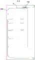
fig. 2 is a front view of a refrigerator in an embodiment of the present invention;
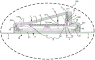
FIG. 3 is a cross-sectional view A-A of FIG. 2;
FIG. 4 is a schematic structural view of a lamp box assembly of the illumination lamp according to the embodiment of the invention;
fig. 5 is a schematic structural view of the lamp box according to the embodiment of the present invention when the first lamp panel is installed;
fig. 6 is a schematic structural view of the lamp box according to the embodiment of the present invention when a second lamp panel is installed;
fig. 7 is a partially enlarged view of the third position-limiting structure in fig. 5.
Detailed Description
The technical solutions in the embodiments of the present invention will be clearly and completely described below with reference to the drawings in the embodiments of the present invention, and it is obvious that the described embodiments are only a part of the embodiments of the present invention, and not all of the embodiments. All other embodiments, which can be derived by a person skilled in the art from the embodiments given herein without making any creative effort, shall fall within the protection scope of the present invention.
In the description of the present invention, it is to be understood that the terms "center", "upper", "lower", "front", "rear", "left", "right", "vertical", "horizontal", "top", "bottom", "inner", "outer", and the like indicate orientations or positional relationships based on those shown in the drawings, and are only for convenience of description and simplicity of description, and do not indicate or imply that the referenced devices or elements must have a particular orientation, be constructed and operated in a particular orientation, and thus, are not to be construed as limiting the present invention.
The terms "first", "second" and "first" are used for descriptive purposes only and are not to be construed as indicating or implying relative importance or implicitly indicating the number of technical features indicated. Thus, a feature defined as "first" or "second" may explicitly or implicitly include one or more of that feature. In the description of the present invention, "a plurality" means two or more unless otherwise specified.
In the description of the present invention, it should be noted that, unless otherwise explicitly specified or limited, the terms "mounted," "connected," and "connected" are to be construed broadly, e.g., as meaning either a fixed connection, a removable connection, or an integral connection; the specific meanings of the above terms in the present invention can be understood in specific cases to those skilled in the art.
Referring to fig. 4, an embodiment of the present invention provides a lamp box assembly of an illumination lamp, including a lamp box 1 and a lamp shade 2 disposed at a light outlet 14 of the lamp box 1, where the lamp box 1 includes a lamp box bottom plate 11 opposite to the lamp shade 2 and a first side wall 12 connected to the lamp box bottom plate 11, a first clamping structure 3 is disposed in the lamp box 1, the first clamping structure 3 is used to fix the first lamp plate 4 on the first side wall 12, the lamp box bottom plate 11 can reflect light emitted by the first lamp plate 4 to the light outlet 14, a second clamping structure 5 is further disposed in the lamp box 1, and the second clamping structure 5 is used to fix the second lamp plate 6 between the lamp box bottom plate 11 and the light outlet 14 along a horizontal direction. The material of the lamp box 1 may be ABS (Acrylonitrile Butadiene Styrene) plastic, HIPS (High Impact Polystyrene) plastic, and the lamp box bottom plate 11 may be polished or sprayed to improve the light reflection effect of the lamp box bottom plate 11.
It should be noted that: first lamp plate 4 and second lamp plate 6 can only be one of them joint on lamp box 1, can not joint on lamp box 1 simultaneously, is in order to prevent that second lamp plate 6 from influencing the light-emitting of the light that first lamp plate 4 sent like this.
Referring to fig. 4, in the lamp box assembly of the illumination lamp provided in the embodiment of the present invention, because the first clamping structure 3 is disposed in the lamp box 1, the first clamping structure 3 is used to fix the first lamp panel 4 on the first side wall 12, and the lamp box bottom plate 11 can reflect the light emitted by the first lamp panel 4 to the light outlet 14, when a surface light source is required to be used for illumination, the first lamp panel 4 can be conveniently clamped on the first side wall 12 through the first clamping structure 3, and the light emitted by the light source (for example, an LED lamp bead, as shown by reference character c in fig. 5) on the first lamp panel 4 can be reflected to the light outlet 14 through the lamp box bottom plate 11, so that the illumination effect of the surface light source can be achieved; because still be equipped with second joint structure 5 in the lamp box 1, second joint structure 5 is used for being fixed in second lamp plate 6 between lamp box bottom plate 11 and light-emitting window 14 along the horizontal direction, when needs adopt the pointolite illumination like this, just can very conveniently joint second lamp plate 6 between lamp box bottom plate 11 and light-emitting window 14 along the horizontal direction, the light that the light source (for example LED lamp pearl, as shown by reference numeral d in figure 6) on the second lamp plate 6 sent just can directly throw out from light-emitting window 14, thereby realize the illumination effect of pointolite. According to the lamp box assembly of the illuminating lamp provided by the embodiment of the invention, the first lamp plate 4 for realizing the irradiation effect of the surface light source is clamped on the lamp box 1 through the first clamping structure 3, and the second lamp plate 6 for realizing the irradiation effect of the point light source is clamped through the second clamping structure 5, namely, the point light source and the surface light source can be installed on one lamp box 1, so that the universality of the lamp box 1 can be improved, the production efficiency can be greatly improved, and the lamp box 1 does not need to design two different structures aiming at the point light source and the surface light source, so that the cost for designing a set of mold can be saved, and the production cost can be reduced.
The first clamping structure 3 is not exclusive, for example, the first clamping structure 3 may be the following structure: as shown in fig. 4 and 5, first clamping structure 3 includes a first buckle close to first side wall 12, first buckle includes elastic arm 31, first end of elastic arm 31 is fixed in on lamp box bottom plate 11, second end is equipped with first pothook 32 towards one side of first side wall 12, clearance 15 that is used for holding first lamp plate 4 has between elastic arm 31 and the first side wall 12, and the position of light source staggers (as shown in fig. 5) on elastic arm 31 and the first lamp plate 4, first pothook 32 is used for clamping the lower limb of first lamp plate 4. Stagger through the position with light source on elastic arm 31 and the first lamp plate 4, mainly be in order to prevent that elastic arm 31 from sheltering from the light that light source sent on first lamp plate 4 like this.
In addition, the first clamping structure 3 may also be an elastic clamping hook extending from the first side wall 12, and the elastic clamping hook is used for clamping the side edges (such as the edge e and the edge f shown in fig. 5) of the first lamp panel 4. Compare the scheme at the side border of the first lamp plate 4 of elasticity pothook joint, the scheme at the lower border of the first lamp plate 4 of the first pothook 32 joint shown in fig. 4 and 5, because first pothook 32 is the lower border of the first lamp plate 4 of joint, first pothook 32 can play the limiting displacement to first lamp plate 4 like this, can prevent the drunkenness of first lamp plate 4 downwards.
The second snap-in structure 5 is also not exclusive, for example the second snap-in structure 5 may be the following: as shown in fig. 4 and fig. 6, the second clamping structure 5 includes a second buckle 51 and a second hook 52 disposed at the second end of the elastic arm 31 and located on the opposite side of the first hook 32, the second buckle 51 and the second hook 52 are disposed oppositely, and the second buckle 51 and the second hook 52 are respectively used for clamping a first edge 61 and a second edge 62 of the second lamp panel 6.
In addition, the second clamping structure 5 can be as follows: the second hook 52 is disposed on the other elastic arm, i.e. the first hook 32 and the second hook 52 do not share one elastic arm 31. Compared with the scheme that the second hook 52 is arranged on the other elastic arm, in the scheme that the second buckle 51 and the second hook 52 are respectively clamped with the second lamp panel 6 as shown in fig. 4 and 6, the second hook 52 and the first hook 32 share one elastic arm 31, so that an elastic arm is not needed to be independently arranged for arranging the second hook 52, the structure of the lamp box 1 can be simplified, the reliability of the structure of the lamp box 1 is improved, the occupied space on the bottom plate 11 of the lamp box can be reduced, and the structural layout on the lamp box 1 is more compact.
The location of the second latch 51 is not exclusive, and for example, the second latch 51 may be fixed to the second sidewall 13, and the second sidewall 13 is a sidewall connected to the lamp box base plate 11 and opposite to the first sidewall 12. As shown in fig. 6, the second latch 51 may be fixed to the lamp housing base plate 11. Compare on second buckle 51 is fixed in second lateral wall 13, when second buckle 51 is fixed in on lamp box bottom plate 11, can reduce the projection area of second buckle 51 on lamp box bottom plate 11, can reduce sheltering from of second buckle 51 to lamp box bottom plate 11 reverberation like this to the light that can make lamp box bottom plate 11 reflect has better area light source effect.
The position relation of the light-emitting direction of the light source on second buckle 51 and first lamp plate 4 is also not unique, for example second buckle 51 can be located the light-emitting direction of the light source on first lamp plate 4, this is because second buckle 51 is less, and the light effect that sends of light source is less on first lamp plate 4. In addition, the second buckle 51 may also be staggered from the light emitting direction of the light source on the first lamp panel 4. Compare second buckle 51 and be located the light-emitting direction of light source on first lamp plate 4, the light-emitting direction of light source staggers on second buckle 51 and first lamp plate 4, can avoid second buckle 51 to the sheltering from of light source outgoing light on first lamp plate 4 to can furthest reduce the influence of second buckle 51 to 11 reverberation of lamp box bottom plate.
In order to enable the first lamp panel 4 and the second lamp panel 6 to be better clamped on the lamp box 1, the lamp box assembly of the illumination lamp provided by the embodiment of the invention further includes a limiting structure 7, as shown in fig. 4, the limiting structure 7 includes a first limiting structure 71 for limiting the first lamp panel 4 to move up and down, a second limiting structure 72 for limiting the second lamp panel 6 to move up and down, as shown in fig. 5 and 7, and a third limiting structure 73 for limiting the first lamp panel 4 to move along the length direction (X direction) thereof. By arranging the first limiting structure 71 and the third limiting structure 73, when the first lamp panel 4 is clamped on the lamp box 1, the first limiting structure 71 can prevent the first lamp panel 4 from moving up and down, and the third limiting structure 73 can prevent the first lamp panel 4 from moving along the length direction of the first lamp panel 4, so that the first lamp panel 4 can be better clamped on the lamp box 1, and the stability of light emission at a light source on the first lamp panel 4 is ensured; through setting up second limit structure 72, when 6 joints of second lamp plate were on lamp box 1, second limit structure 72 just can prevent that second lamp plate 6 from reciprocating to can make 6 joints of second lamp plate better on lamp box 1, and then guaranteed the stability of second lamp plate 6 light source department light-emitting.
Wherein, first limit structure 71 is not only, for example first limit structure 71 can be for being fixed in the last border of first lamp plate 4 and being used for the limiting plate that leans on with lamp box bottom plate 11 counterbalance. In addition, the first stopper structure 71 may have the following structure: as shown in fig. 4, the first limiting structure 71 includes a first limiting rib 711 fixed on the lamp box bottom plate 11 and used for abutting against the upper edge of the first lamp panel 4. Compare the scheme that sets up the limiting plate at the last border of first lamp plate 4, set up the scheme of first spacing muscle 711 on lamp box bottom plate 11, the structural change of not doing of first lamp plate 4 can guarantee the commonality of first lamp plate 4 like this, also can avoid the increase of first lamp plate 4 design and manufacturing cost that the structural change brought simultaneously.
The second limiting structure 72 is also not unique, for example, the second limiting structure 72 may be a limiting rib plate fixed on the upper surface of the second lamp panel 6 and used for abutting against the lamp box bottom plate 11. In addition, the second limit structure 72 may have the following structure: as shown in fig. 4, 5 and 6, the second limiting structure 72 includes a second limiting rib 721 fixed on the lamp box bottom plate 11 and used for abutting against the upper surface of the second lamp panel 6. Compare the scheme that sets up spacing gusset at the upper surface of second lamp plate 6, in the scheme that sets up spacing muscle 721 of second on lamp box bottom plate 11, the structural change of not doing of second lamp plate 6 can guarantee the commonality of second lamp plate 6 like this, also can avoid the increase of second lamp plate 6 design and manufacturing cost that the structural change brought simultaneously.
The number of the second limiting ribs 721 can be set to one, and the second limiting ribs 721 are disposed on the third edge 63 or the fourth edge 64 of the second lamp panel 6. In addition, as shown in fig. 5 and fig. 6, the second limiting ribs 721 may also include two, and the two second limiting ribs 721 are correspondingly disposed at the third edge 63 and the fourth edge 64 of the second lamp panel 6 (as shown in fig. 6). Compare the figure of the spacing muscle 721 of second and set up the scheme into one, in the scheme that the spacing muscle 721 of second includes two, two spacing muscle 721 of second can carry on spacingly to the both ends of 6 length direction of second lamp plate (be the X direction in figure 6 promptly), can restrict reciprocating at 6 length direction's of second lamp plate both ends better, avoid second lamp plate 6 to produce the slope to can guarantee the stability of light source emission light on 6 second lamp plates.
Referring to fig. 4 and 5, in the second limiting rib 721, a step surface 7211 is formed at the lower end of the second limiting rib 721, a horizontal surface 7211a of the step surface 7211 abuts against the upper surface of the second lamp panel 6, so that the horizontal surface 7211a of the step surface 7211 can limit the upward movement of the second lamp panel 6, and the second limiting rib 721, the second buckle 51 and the second hook 52 together firmly clamp the second lamp panel 6 on the lamp box 1; as shown in fig. 5, the vertical surface 7211b of the stepped surface 7211 abuts against the side surface of the second lamp panel 6, so that the vertical surface 7211b of the stepped surface 7211 can limit the second lamp panel 6, and the second lamp panel 6 can be prevented from moving in the length direction.
The third limiting structure 73 is also not exclusive, for example, the third limiting structure 73 may be the following structure: as shown in fig. 5 and 7, the third limiting structure 73 includes a third limiting rib 731 disposed on the first side wall 12 and a limiting groove 732 disposed on the first lamp plate 4, the third limiting rib 731 extends into the limiting groove 732, and both side groove walls of the limiting groove 732 in the length direction of the first lamp plate 4 abut against the third limiting rib 731. Through the support of third spacing muscle 731 and spacing groove 732 along the ascending both sides cell wall of first lamp plate 4 length direction, can realize that first lamp plate is spacing on its length direction.
In addition, the third limiting structure 73 may be the following structure: the through hole has been seted up on first lamp plate 4, has seted up the locating hole on the first lateral wall 12 that corresponds with the through hole, and the locating pin cooperation passes the through hole to insert in the locating hole, can realize first lamp plate 4 spacing on its length direction through the locating pin. Compare first lamp plate 4 and realize at its length direction spacing scheme through the locating pin, the scheme shown in figure 7, the structure is simpler, need not additionally to add spacing part to can make things convenient for the installation of first lamp plate 4.
Referring to fig. 4, the cover 2 includes a cover body 21 made of a transparent material, and a cover rim 22 made of an opaque material. The lampshade body 21 is made of transparent materials, so that light rays emitted by the light source on the first lamp panel 4 or the second lamp panel 6 can penetrate through the lampshade body 21 and can be emitted from the light outlet 14; the lampshade wrapping 22 is made of opaque materials, so that the lampshade wrapping 22 can shield the structure inside the lamp box 1, and the appearance attractiveness is facilitated.
The connection mode of the lampshade edge 22 and the lampshade body 21 is not unique, for example, the lampshade edge 22 and the lampshade body 21 can be welded together by ultrasonic welding, or the lampshade edge 22 and the lampshade body 21 can be formed by one-step injection molding through double-color injection molding. In addition, as shown in fig. 4, the cover rim 22 may be fastened to the periphery of the cover body 21. Compared with the scheme that the lampshade wrapping 22 and the lampshade body 21 are welded together through ultrasonic waves, the scheme that the lampshade wrapping 22 and the lampshade body 21 are clamped is convenient for dismounting, the assembling mode between the lampshade wrapping 22 and the lampshade body 21 is simple, and ultrasonic welding equipment is not used, so that the assembling cost between the lampshade wrapping 22 and the lampshade body is reduced; compared with the scheme that the lampshade wrapping 22 and the lampshade body 21 are formed through double-shot injection molding, the scheme that the lampshade wrapping 22 and the lampshade body 21 are clamped, the lampshade wrapping 22 and the lampshade body 21 are manufactured in a split mode through a common injection mold, and a double-shot injection molding mold is not needed, so that the cost of the mold can be reduced; meanwhile, the lampshade wrapping 22 is clamped with the lampshade body 21, the assembling mode is simple, the lampshade wrapping and the lampshade body are convenient to disassemble and assemble, and therefore the assembling cost between the lampshade wrapping and the lampshade body is reduced.
The connection mode of the lampshade edge 22 and the lamp box 1 is not unique, for example, the lampshade edge 22 can be integrally formed with the lamp box 1, and then the lampshade body 21 is connected with the lamp box 1 through a buckle. As shown in fig. 4, the lampshade covering 22 may also be provided with a third buckle 221, the light outlet 14 of the lamp box 1 is provided with a clamping table 16, and the third buckle 221 is clamped on the clamping table 16. During assembly, the lampshade body 21 can be firstly installed from the upper end of the lampshade wrapping 22 and clamped on the lampshade wrapping 22, and then the lampshade wrapping 22 is clamped on the lamp box 1. Compared with the scheme that the lampshade wrapping 22 and the lamp box 1 are integrally formed, the scheme that the lampshade wrapping 22 is clamped with the lamp box 1 through the third buckle 221 is adopted, the lampshade body 21 can be assembled from the upper end of the lampshade wrapping 22 and clamped on the lampshade wrapping 22, and therefore the lampshade body 21 can be conveniently fixed on the lampshade wrapping 22; meanwhile, the lampshade wrapping 22 is clamped with the lamp box 1 through the third buckle 221, the appearance of the lampshade wrapping 22 can be designed independently, different appearances can be designed for the lampshade wrapping 22, and the lampshade body 21 is clamped on the lampshade wrapping 22, so that the whole formed by the lampshade wrapping 22 and the lampshade body can form different appearance appearances, and different visual requirements of customers can be met.
An embodiment of the present invention further provides a refrigerator, as shown in fig. 2, fig. 3, and fig. 4, including a cabinet liner 200, a lamp box assembly 100 of the illumination lamp described in any of the above embodiments is disposed on an inner wall (denoted by reference numeral h in fig. 3 and fig. 4) of the cabinet liner 200, and a first lamp panel 4 is fixed on a first side wall 12 of a lamp box 1 in the lamp box assembly 100, or a second lamp panel 6 is fixed between a lamp box bottom plate 11 of the lamp box 1 and a light outlet 14.
It should be noted that: the lamp box assembly 100 of the illumination lamp in any of the above embodiments can be used not only in a refrigerator, but also in an electrical appliance requiring illumination, such as a wine cabinet, a display cabinet, and the like.
In the refrigerator provided by the embodiment of the present invention, as shown in fig. 2, fig. 3 and fig. 4, since the lamp box assembly 100 of the illumination lamp described in any one of the above embodiments is disposed on the inner wall of the container 200, when the interior of the container 200 needs to be illuminated by a surface light source, the first lamp panel 4 can be conveniently clamped on the first side wall 12 through the first clamping structure 3, and light emitted by the light source on the first lamp panel 4 can be reflected to the light outlet 14 through the lamp box bottom plate 11, so that an illumination effect of the surface light source can be achieved; when the inside pointolite illumination that needs of case courage 200, just can very conveniently along the horizontal direction joint second lamp plate 6 between lamp box bottom plate 11 and light-emitting window 14, the light that the light source on the second lamp plate 6 sent just can directly throw out from light-emitting window 14 to realize the effect of shining of pointolite. Because both can install first lamp plate 4 on the lamp box 1, can install second lamp plate 6 again, just so can improve lamp box 1's commonality, production efficiency just can improve by a wide margin, and lamp box 1 just need not design two kinds of different structures to pointolite and surface light source respectively, consequently just can practice thrift the expense of designing one set of mould to can reduce the lamp box subassembly 100 manufacturing cost of light, and then can reduce the manufacturing cost of refrigerator.
As shown in fig. 4, the lamp box assembly 100 of the lighting lamp can be connected to the inner wall of the container 200 through the fifth hook 110 and the sixth hook 120, so that when the lamp box assembly 100 of the lighting lamp needs to be replaced, the lamp box assembly 100 of the lighting lamp can be conveniently detached from the inner wall of the container 200 through the fifth hook and the sixth hook.
The above description is only for the specific embodiments of the present invention, but the scope of the present invention is not limited thereto, and any person skilled in the art can easily conceive of the changes or substitutions within the technical scope of the present invention, and the changes or substitutions should be covered within the scope of the present invention. Therefore, the protection scope of the present invention shall be subject to the protection scope of the claims.
Claims (11)
1. The utility model provides a lamp box subassembly of light, its characterized in that, including the lamp box with set up in the lamp shade of light-emitting port department of lamp box, the lamp box include with the lamp box bottom plate that the lamp shade is relative and with the first lateral wall that the lamp box bottom plate is connected, be equipped with first joint structure in the lamp box, first joint structure is used for being fixed in first lamp plate on the first lateral wall, the lamp box bottom plate can with the light reflection that first lamp plate sent extremely the light-emitting port, still be equipped with second joint structure in the lamp box, second joint structure is used for being fixed in second lamp plate along the horizontal direction the lamp box bottom plate with between the light-emitting port.
2. The light box assembly of the lighting lamp according to claim 1, wherein the first clamping structure comprises a first buckle close to the first side wall, the first buckle comprises an elastic arm, a first end of the elastic arm is fixed on the light box bottom plate, a first clamping hook is arranged at one side of the second end facing the first side wall, a gap for accommodating the first light plate is formed between the elastic arm and the first side wall, the position of the light source on the elastic arm and the first light plate are staggered, and the first clamping hook is used for clamping the lower edge of the first light plate.
3. The lamp box assembly of the lighting lamp according to claim 2, wherein the second clamping structure comprises a second buckle and a second hook disposed at the second end of the elastic arm and located on the opposite side of the first hook, the second buckle and the second hook are disposed oppositely, and the second buckle and the second hook are respectively used for clamping a first edge and a second edge of the second lamp panel which are opposite to each other.
4. The light box assembly of the illumination lamp according to claim 3, wherein the second buckle is fixed on the light box bottom plate, and the second buckle is staggered with the light emitting direction of the light source on the first light plate.
5. The lamp box assembly of the lighting lamp according to claim 3, further comprising a limiting structure, wherein the limiting structure comprises a first limiting structure for limiting the first lamp panel to move up and down, a second limiting structure for limiting the second lamp panel to move up and down, and a third limiting structure for limiting the first lamp panel to move along the length direction of the first lamp panel.
6. The lamp box assembly of the lighting lamp according to claim 5, wherein the first limiting structure comprises a first limiting rib fixed on the lamp box bottom plate and used for abutting against the upper edge of the first lamp panel.
7. The light box assembly of the illumination lamp according to claim 5, wherein the second limiting structure comprises a second limiting rib fixed on the light box bottom plate and used for abutting against the upper surface of the second light plate.
8. The lamp box assembly of the lighting lamp according to claim 7, wherein the number of the second limiting ribs is two, the second limiting ribs are correspondingly arranged at the third edge and the fourth edge of the second lamp panel, which are opposite to each other, a step surface is formed at the lower end of each second limiting rib, the horizontal surface of the step surface is abutted against the upper surface of the second lamp panel, and the vertical surface of the step surface is abutted against the side surface of the second lamp panel.
9. The light box assembly of the illumination lamp according to claim 5, wherein the third limiting structure comprises a third limiting rib arranged on the first side wall and a limiting groove arranged on the first light plate, the third limiting rib extends into the limiting groove, and the two side groove walls of the limiting groove along the length direction of the first light plate are abutted against the third limiting rib.
10. The light box assembly of the lighting lamp according to any one of claims 1 to 9, wherein the lamp cover comprises a lamp cover body made of a transparent material and a lamp cover wrapping edge made of an opaque material, the lamp cover wrapping edge is clamped on the edge of the lamp cover body for a circle, a third buckle is arranged on the lamp cover wrapping edge, a clamping table is arranged at a light outlet of the light box, and the third buckle is clamped on the clamping table.
11. The refrigerator comprises a refrigerator liner and is characterized in that the inner wall of the refrigerator liner is provided with the lamp box assembly of the illuminating lamp according to any one of claims 1 to 10, a first lamp panel is fixed on a first side wall of a lamp box in the lamp box assembly, or a second lamp panel is fixed between a lamp box bottom plate of the lamp box and a light outlet.
Priority Applications (1)
| Application Number | Priority Date | Filing Date | Title |
|---|---|---|---|
| CN201710656842.6A CN107525036B (en) | 2017-08-03 | 2017-08-03 | Lamp box assembly of illuminating lamp and refrigerator |
Applications Claiming Priority (1)
| Application Number | Priority Date | Filing Date | Title |
|---|---|---|---|
| CN201710656842.6A CN107525036B (en) | 2017-08-03 | 2017-08-03 | Lamp box assembly of illuminating lamp and refrigerator |
Publications (2)
| Publication Number | Publication Date |
|---|---|
| CN107525036A CN107525036A (en) | 2017-12-29 |
| CN107525036B true CN107525036B (en) | 2020-01-10 |
Family
ID=60680488
Family Applications (1)
| Application Number | Title | Priority Date | Filing Date |
|---|---|---|---|
| CN201710656842.6A Active CN107525036B (en) | 2017-08-03 | 2017-08-03 | Lamp box assembly of illuminating lamp and refrigerator |
Country Status (1)
| Country | Link |
|---|---|
| CN (1) | CN107525036B (en) |
Families Citing this family (2)
| Publication number | Priority date | Publication date | Assignee | Title |
|---|---|---|---|---|
| DE102018001168B3 (en) * | 2018-02-05 | 2019-05-16 | Emz-Hanauer Gmbh & Co. Kgaa | Domestic refrigerator with a wall light module |
| CN110440508A (en) * | 2018-05-02 | 2019-11-12 | 合肥美的电冰箱有限公司 | Anticreep assembling structure and refrigerator |
Citations (7)
| Publication number | Priority date | Publication date | Assignee | Title |
|---|---|---|---|---|
| CN203190389U (en) * | 2013-01-31 | 2013-09-11 | 广德润视机电有限公司 | Seal assembly of LED illuminating lamp |
| CN203893567U (en) * | 2014-05-15 | 2014-10-22 | 湖北美的电冰箱有限公司 | Refrigerator and lamp box assembly for same |
| CN204176447U (en) * | 2014-09-24 | 2015-02-25 | 合肥美的电冰箱有限公司 | Illuminating lamp and refrigerator |
| CN204438661U (en) * | 2014-12-18 | 2015-07-01 | Tcl智能科技(合肥)有限公司 | Refrigerator and lamp case assembly thereof |
| CN205825583U (en) * | 2016-04-15 | 2016-12-21 | 河南新飞电器有限公司 | A kind of refrigerator combines with freezing illuminating lamp |
| CN206094737U (en) * | 2016-08-31 | 2017-04-12 | 海信(山东)冰箱有限公司 | Refrigerator lighting components and refrigerator |
| CN206130708U (en) * | 2016-10-17 | 2017-04-26 | 青岛海尔股份有限公司 | Refrigerator and lighting parts thereof |
-
2017
- 2017-08-03 CN CN201710656842.6A patent/CN107525036B/en active Active
Patent Citations (7)
| Publication number | Priority date | Publication date | Assignee | Title |
|---|---|---|---|---|
| CN203190389U (en) * | 2013-01-31 | 2013-09-11 | 广德润视机电有限公司 | Seal assembly of LED illuminating lamp |
| CN203893567U (en) * | 2014-05-15 | 2014-10-22 | 湖北美的电冰箱有限公司 | Refrigerator and lamp box assembly for same |
| CN204176447U (en) * | 2014-09-24 | 2015-02-25 | 合肥美的电冰箱有限公司 | Illuminating lamp and refrigerator |
| CN204438661U (en) * | 2014-12-18 | 2015-07-01 | Tcl智能科技(合肥)有限公司 | Refrigerator and lamp case assembly thereof |
| CN205825583U (en) * | 2016-04-15 | 2016-12-21 | 河南新飞电器有限公司 | A kind of refrigerator combines with freezing illuminating lamp |
| CN206094737U (en) * | 2016-08-31 | 2017-04-12 | 海信(山东)冰箱有限公司 | Refrigerator lighting components and refrigerator |
| CN206130708U (en) * | 2016-10-17 | 2017-04-26 | 青岛海尔股份有限公司 | Refrigerator and lighting parts thereof |
Also Published As
| Publication number | Publication date |
|---|---|
| CN107525036A (en) | 2017-12-29 |
Similar Documents
| Publication | Publication Date | Title |
|---|---|---|
| CN107525036B (en) | Lamp box assembly of illuminating lamp and refrigerator | |
| CN102927761B (en) | Fan guard and the refrigerator with this fan guard | |
| CN204901657U (en) | Illumination lamp shade, refrigerator lighting device and refrigerator | |
| KR102117794B1 (en) | LED lighting | |
| CN205402373U (en) | Projection lamp | |
| CN102901306B (en) | Air channel cover plate assembly for refrigerator and refrigerator having same | |
| CN209977775U (en) | Lamp for illumination in cabinet, illumination system and storage cabinet | |
| CN210979552U (en) | Ceiling lamp | |
| CN111156780A (en) | Refrigerator door body and refrigerator with same | |
| CN215809655U (en) | Atmosphere lamp assembly structure and refrigerator | |
| CN215765928U (en) | Door body and refrigerator | |
| CN209445217U (en) | Lamps and lanterns | |
| CN108679510B (en) | Decorative lamp mounting structure and refrigerator | |
| CN111156779B (en) | Refrigerator door body decorative strip assembly, refrigerator door body and installation method of refrigerator door body | |
| CN105546422A (en) | Projection lamp | |
| CN203586672U (en) | Refrigerator controller box mounting structure | |
| CN219063261U (en) | Ceiling lamp | |
| WO2022205889A1 (en) | Door for refrigerator and refrigerator | |
| CN108444199B (en) | Decorative lamp mounting structure and refrigerator | |
| CN219828653U (en) | Atmosphere down lamp with double luminous forms | |
| CN216114974U (en) | Display module, air duct cover plate and refrigeration equipment | |
| CN110686191A (en) | Anti-dazzle mesh illumination structure of furniture drawer | |
| CN212673066U (en) | Ceiling interior lamp optical system | |
| CN214249346U (en) | Anti-dazzling ceiling lamp | |
| CN217559757U (en) | Simple LED wall lamp |
Legal Events
| Date | Code | Title | Description |
|---|---|---|---|
| PB01 | Publication | ||
| PB01 | Publication | ||
| SE01 | Entry into force of request for substantive examination | ||
| SE01 | Entry into force of request for substantive examination | ||
| GR01 | Patent grant | ||
| GR01 | Patent grant |