CN107455012B - Establishing secure NAN data links - Google Patents
Establishing secure NAN data links Download PDFInfo
- Publication number
- CN107455012B CN107455012B CN201680017263.0A CN201680017263A CN107455012B CN 107455012 B CN107455012 B CN 107455012B CN 201680017263 A CN201680017263 A CN 201680017263A CN 107455012 B CN107455012 B CN 107455012B
- Authority
- CN
- China
- Prior art keywords
- message
- ndp
- sta
- schedule
- data link
- Prior art date
- Legal status (The legal status is an assumption and is not a legal conclusion. Google has not performed a legal analysis and makes no representation as to the accuracy of the status listed.)
- Active
Links
Images


Classifications
-
- H—ELECTRICITY
- H04—ELECTRIC COMMUNICATION TECHNIQUE
- H04W—WIRELESS COMMUNICATION NETWORKS
- H04W12/00—Security arrangements; Authentication; Protecting privacy or anonymity
- H04W12/06—Authentication
-
- H—ELECTRICITY
- H04—ELECTRIC COMMUNICATION TECHNIQUE
- H04L—TRANSMISSION OF DIGITAL INFORMATION, e.g. TELEGRAPHIC COMMUNICATION
- H04L63/00—Network architectures or network communication protocols for network security
- H04L63/04—Network architectures or network communication protocols for network security for providing a confidential data exchange among entities communicating through data packet networks
-
- H—ELECTRICITY
- H04—ELECTRIC COMMUNICATION TECHNIQUE
- H04L—TRANSMISSION OF DIGITAL INFORMATION, e.g. TELEGRAPHIC COMMUNICATION
- H04L63/00—Network architectures or network communication protocols for network security
- H04L63/06—Network architectures or network communication protocols for network security for supporting key management in a packet data network
- H04L63/062—Network architectures or network communication protocols for network security for supporting key management in a packet data network for key distribution, e.g. centrally by trusted party
-
- H—ELECTRICITY
- H04—ELECTRIC COMMUNICATION TECHNIQUE
- H04L—TRANSMISSION OF DIGITAL INFORMATION, e.g. TELEGRAPHIC COMMUNICATION
- H04L63/00—Network architectures or network communication protocols for network security
- H04L63/06—Network architectures or network communication protocols for network security for supporting key management in a packet data network
- H04L63/065—Network architectures or network communication protocols for network security for supporting key management in a packet data network for group communications
-
- H—ELECTRICITY
- H04—ELECTRIC COMMUNICATION TECHNIQUE
- H04L—TRANSMISSION OF DIGITAL INFORMATION, e.g. TELEGRAPHIC COMMUNICATION
- H04L63/00—Network architectures or network communication protocols for network security
- H04L63/12—Applying verification of the received information
- H04L63/123—Applying verification of the received information received data contents, e.g. message integrity
-
- H—ELECTRICITY
- H04—ELECTRIC COMMUNICATION TECHNIQUE
- H04L—TRANSMISSION OF DIGITAL INFORMATION, e.g. TELEGRAPHIC COMMUNICATION
- H04L65/00—Network arrangements, protocols or services for supporting real-time applications in data packet communication
- H04L65/60—Network streaming of media packets
- H04L65/61—Network streaming of media packets for supporting one-way streaming services, e.g. Internet radio
- H04L65/611—Network streaming of media packets for supporting one-way streaming services, e.g. Internet radio for multicast or broadcast
-
- H—ELECTRICITY
- H04—ELECTRIC COMMUNICATION TECHNIQUE
- H04W—WIRELESS COMMUNICATION NETWORKS
- H04W12/00—Security arrangements; Authentication; Protecting privacy or anonymity
- H04W12/04—Key management, e.g. using generic bootstrapping architecture [GBA]
-
- H—ELECTRICITY
- H04—ELECTRIC COMMUNICATION TECHNIQUE
- H04W—WIRELESS COMMUNICATION NETWORKS
- H04W12/00—Security arrangements; Authentication; Protecting privacy or anonymity
- H04W12/50—Secure pairing of devices
-
- H—ELECTRICITY
- H04—ELECTRIC COMMUNICATION TECHNIQUE
- H04W—WIRELESS COMMUNICATION NETWORKS
- H04W48/00—Access restriction; Network selection; Access point selection
- H04W48/16—Discovering, processing access restriction or access information
-
- H—ELECTRICITY
- H04—ELECTRIC COMMUNICATION TECHNIQUE
- H04W—WIRELESS COMMUNICATION NETWORKS
- H04W72/00—Local resource management
- H04W72/12—Wireless traffic scheduling
-
- H—ELECTRICITY
- H04—ELECTRIC COMMUNICATION TECHNIQUE
- H04W—WIRELESS COMMUNICATION NETWORKS
- H04W72/00—Local resource management
- H04W72/12—Wireless traffic scheduling
- H04W72/1263—Mapping of traffic onto schedule, e.g. scheduled allocation or multiplexing of flows
-
- H—ELECTRICITY
- H04—ELECTRIC COMMUNICATION TECHNIQUE
- H04W—WIRELESS COMMUNICATION NETWORKS
- H04W72/00—Local resource management
- H04W72/20—Control channels or signalling for resource management
-
- H—ELECTRICITY
- H04—ELECTRIC COMMUNICATION TECHNIQUE
- H04W—WIRELESS COMMUNICATION NETWORKS
- H04W72/00—Local resource management
- H04W72/30—Resource management for broadcast services
-
- H—ELECTRICITY
- H04—ELECTRIC COMMUNICATION TECHNIQUE
- H04W—WIRELESS COMMUNICATION NETWORKS
- H04W76/00—Connection management
- H04W76/10—Connection setup
-
- H—ELECTRICITY
- H04—ELECTRIC COMMUNICATION TECHNIQUE
- H04W—WIRELESS COMMUNICATION NETWORKS
- H04W76/00—Connection management
- H04W76/10—Connection setup
- H04W76/14—Direct-mode setup
-
- H—ELECTRICITY
- H04—ELECTRIC COMMUNICATION TECHNIQUE
- H04W—WIRELESS COMMUNICATION NETWORKS
- H04W8/00—Network data management
-
- H—ELECTRICITY
- H04—ELECTRIC COMMUNICATION TECHNIQUE
- H04W—WIRELESS COMMUNICATION NETWORKS
- H04W8/00—Network data management
- H04W8/005—Discovery of network devices, e.g. terminals
Abstract
A method, apparatus, and computer-readable medium for wireless communication are provided. In one aspect, an apparatus is configured to determine to initiate a security negotiation with a publishing device to establish a secure NDP, wherein the publishing device is an authenticator and a subscribing device is a supplicant in the security negotiation. The apparatus is configured to transmit an initiation message to a publishing device that is providing NAN service to initiate a security negotiation for establishing a secure NDP. The initiation message may indicate that the publishing device is to be the authenticator in the security negotiation.
Description
Cross Reference to Related Applications
This application claims us provisional application S/n.62/137,125 entitled "CONNECTION SETUP FOR NAN data link with NAN data link time block" filed 3/23/2015, us provisional application S/n.62/137,125 entitled "SCHEDULE SELECTION AND CONNECTION SETUP BETWEEN devices participating in NAN data link" filed 5/22/2015, us provisional application S/n.62/165,652 entitled "SCHEDULE SELECTION AND CONNECTION SETUP BETWEEN devices participating in NAN data link" filed 18/2015, us provisional application S/n.62/181,722 entitled "SCHEDULE SELECTION AND CONNECTION SETUP BETWEEN devices participating in NAN data link" filed 8/20/2015 SCHEDULE SELECTION AND CONNECTION SETUP BETWEEN devices of a way) "us provisional application S/n.62/207,874, us provisional application S/n.62/249,870 entitled" SCHEDULE SELECTION AND CONNECTION SETUP BETWEEN devices participating in a NAN data link "filed on day 2/11/2015, us provisional application S/n.62/3656 entitled" SCHEDULE SELECTION AND CONNECTION SETUP BETWEEN devices participating in a NAN data link "filed on day 30/11/2015, us provisional application S/n.62/261,266 entitled" SCHEDULE SELECTION AND CONNECTION SETUP BETWEEN devices participating in a NAN data link "filed on day 30/11/2015, AND us provisional application S/n.62/298,398 entitled" SCHEDULE SELECTION AND CONNECTION SETUP BETWEEN devices participating in a NAN data link "filed on day 22/2016, AND U.S. patent application No.15/076,201 entitled "SCHEDULE SELECTION AND CONNECTION SETUP BETWEEN devices participating in a NAN data link" filed on 21/3/2016, the entire contents of which are expressly incorporated herein by reference.
Background
FIELD
The present disclosure relates generally to communication systems, and more particularly to scheduling selection and connection setup between devices participating in a Neighbor Awareness Networking (NAN) data link (NDL), which may be associated with one or more NAN Data Paths (NDPs).
Background
In many telecommunication systems, a communication network is used to exchange messages between several spatially separated interacting devices. Networks may be classified according to geographic scope, which may be, for example, a city area, a local area, or a personal area. Such networks may be designated as Wide Area Networks (WANs), Metropolitan Area Networks (MANs), Local Area Networks (LANs), Wireless Local Area Networks (WLANs), or Personal Area Networks (PANs), respectively. The networks also vary according to the switching/routing technology used to interconnect the various network nodes and devices (e.g., circuit switching versus packet switching), the type of physical medium used for transmission (e.g., wired versus wireless), and the set of communication protocols used (e.g., internet protocol suite, Synchronous Optical Networking (SONET), ethernet, etc.).
Wireless networks tend to be preferred when network elements are mobile and thus have dynamic connectivity requirements, or where the network architecture is formed in an ad hoc (ad hoc) topology rather than a fixed topology. Wireless networks employ intangible physical media in an unguided propagation mode using electromagnetic waves in the radio, microwave, infrared, optical, etc. frequency bands. Wireless networks advantageously facilitate user mobility and rapid field deployment when compared to fixed wired networks.
SUMMARY
The system, method, computer-readable medium, and apparatus of the present invention each have several aspects, no single one of which is solely responsible for the desirable attributes of the present invention. Without limiting the scope of the invention as expressed by the claims which follow, some features will now be discussed briefly. After considering this discussion, and particularly after reading the section entitled "detailed description" one will understand how the features of this invention provide advantages to devices in a wireless network.
One aspect of the present disclosure provides an apparatus (e.g., a station or an access point) for wireless communication. The apparatus is configured to receive a message from a second wireless device. The message includes wakeup information associated with the second wireless device for connection setup and includes time block information indicating whether any data link time blocks (DL-TBs) are used by the second wireless device for data communication. The apparatus is configured to determine one or more wake-up times associated with the second wireless device for connection setup based on the wake-up information and the time block information included in the message. The apparatus is configured to establish a connection with the second wireless device based on the determined one or more wake-up times associated with the second wireless device.
Another aspect of the disclosure provides an apparatus (e.g., a station or an access point) for wireless communication. The apparatus is configured to transmit a message to a second wireless device. The message includes wakeup information associated with the first wireless device for connection setup and includes time block information indicating whether any DL-TBs are used by the first wireless device for data communication. The apparatus is configured to receive a connection setup message from the second wireless device based on the wake-up information and the time block information included in the message. The apparatus is configured to establish a connection with a second wireless device based on the received connection setup message.
Another aspect of the disclosure provides an apparatus (e.g., a station or an access point) for wireless communication. The apparatus is configured to determine a schedule for communicating data in a NAN. The apparatus is configured to communicate data over a data link within the NAN based on the determined schedule.
Another aspect of the disclosure provides an apparatus (e.g., a station or an access point) for wireless communication. The apparatus is configured to determine a schedule for communicating data over a data link within a NAN. The apparatus is configured to communicate data with a second wireless device based on the determined schedule.
Another aspect of the disclosure provides an apparatus (e.g., a station or an access point) for wireless communication. The apparatus is configured to determine a data link attribute for scheduling a data link with the second wireless device and transmit the determined data link attribute to the second wireless device in a frame.
Another aspect of the disclosure provides an apparatus (e.g., a station or an access point) for wireless communication. The apparatus is configured to determine a multicast schedule for communicating data associated with a service on an NDL and transmit the multicast schedule to at least one other wireless device.
Another aspect of the disclosure provides an apparatus (e.g., a station or an access point) for wireless communication. The apparatus is configured to transmit a message to a second wireless device to request a multicast schedule for communicating data associated with the NDL, and receive a second message from the second wireless device based on the transmitted message. The second message may include a multicast schedule for communicating data associated with the service on the NDL.
Another aspect of the disclosure provides an apparatus (e.g., a station or an access point) for wireless communication. The apparatus is configured to determine to initiate a security negotiation with a publishing device to establish a secure NDP, wherein the publishing device is an authenticator in the security negotiation and the apparatus (e.g., subscribing device) is a supplicant. The apparatus is configured to transmit an initiation message to a publishing device that is providing NAN service to initiate a security negotiation for establishing a secure NDP. The initiation message may indicate that the publishing device is to be the authenticator in the security negotiation.
Another aspect of the disclosure provides an apparatus (e.g., a station or an access point) for wireless communication. The apparatus may be a publishing device. The apparatus is configured to receive an initiation message from a subscribing device that is requesting NAN service to initiate a security negotiation associated with an NDP. The initiation message may indicate that the issuing device is an authenticator in the security negotiation. The apparatus is configured to determine, based on the received initiation message, that the publishing device is an authenticator in the security negotiation and that the subscribing device is a supplicant.
Brief Description of Drawings
Fig. 1 illustrates an example wireless communication system in which aspects of the present disclosure may be employed.
Fig. 2A is an exemplary diagram of a communication interval.
Fig. 2B illustrates an exemplary call flow diagram of data link connection setup in a NAN.
Fig. 3 is a flow diagram of an example method for determining a time for setting up a data link in a NAN.
Fig. 4 is a flow diagram of an example method for enabling determination of a time for setting up a data link in a NAN.
Fig. 5A is a diagram with an example of availability information.
Fig. 5B illustrates availability attributes for determining the availability of a wireless device for scheduling a data link.
Fig. 6 is a call flow diagram illustrating a first negotiated approach for pair-wise connection setup using availability information.
Fig. 7A and 7B are call flow diagrams illustrating a second negotiated approach for pair-wise connection setup using availability information.
Fig. 8 is a call flow diagram illustrating a third negotiated approach for performing one-to-many connection setup based on availability information.
Fig. 9 is a call flow diagram illustrating a non-negotiated approach for using service provider scheduling with standardized periodic time blocks for data links.
Fig. 10 is a call flow diagram illustrating a non-negotiated approach for determining a schedule for a data link using a profile associated with a service.
Fig. 11 is a call flow diagram illustrating a non-negotiated approach for using default NDL scheduling for a data link.
Fig. 12 is a call flow diagram illustrating a hybrid approach for using predetermined NDL scheduling and negotiated NDL scheduling for a data link.
Fig. 13A is a flow diagram of an exemplary method of a service recipient performing a first negotiated approach for pair-wise connection setup using availability information.
Fig. 13B is a flow diagram of an exemplary method by which a wireless device performs a first variant of the second negotiated approach for paired connection setup using availability information.
Fig. 14 is a flow diagram of an exemplary method by which a service recipient/provider performs a second variant of the second negotiated approach for pair-wise connection setup using availability information.
Fig. 15 is a flow diagram of an exemplary method by which a service recipient performs a third negotiated approach for performing one-to-many connection setup based on availability information.
Fig. 16 is a flow diagram of an exemplary method by which a service recipient performs a non-negotiated approach for using a service provider schedule with standardized periodic time blocks for a data link.
Fig. 17 is a flow diagram of an exemplary method by which a service provider performs a first negotiated approach for pair-wise connection setup using availability information.
Fig. 18 is a flow diagram of an exemplary method by which a service provider performs a third negotiated approach for pair-wise connection setup using availability information.
Fig. 19 is a flow diagram of an exemplary method for a service provider to use a non-negotiated approach for determining a service provider schedule for a data link with standardized periodic blocks of time.
Fig. 20 is a flow diagram of an exemplary method by which a service provider uses a non-negotiated approach for determining a schedule for a data link using a profile associated with a service.
Fig. 21 is a flow diagram of an exemplary method for a service provider to use a non-negotiated approach using a default NDL schedule for a data link.
Fig. 22 is a flow diagram of an exemplary method by which a service provider uses a hybrid approach that utilizes a predetermined NDL schedule and a negotiated NDL schedule for a data link.
Fig. 23 illustrates an example functional block diagram of a wireless device that may perform NAN connection setup within the wireless communication system of fig. 1.
Fig. 24 is a functional block diagram of an example wireless communication device that performs connection setup.
Fig. 25 illustrates data link attributes used to determine availability of a wireless device for scheduling a data link.
Fig. 26A is a call flow diagram illustrating a first exemplary data link setup using data link attributes.
Fig. 26B is a call flow diagram illustrating a second exemplary data link setup using data link attributes.
Fig. 27 illustrates a table that gives the potential behavior of a wireless device based on operating mode.
Fig. 28 illustrates an example functional block diagram of a wireless device that may utilize data link attributes to perform connection setup within the wireless communication system of fig. 1.
Fig. 29 is a flow diagram of an exemplary method for connection scheduling using data link attributes.
Fig. 30 is a flow diagram of an exemplary method of determining a data link schedule based on an operating mode.
Fig. 31 is a functional block diagram of an example wireless communication device that performs connection setup.
Fig. 32 is a diagram illustrating NAN clusters.
Fig. 33 is a diagram illustrating NAN Data Clustering (NDC).
Fig. 34 is a diagram illustrating NDL scheduling of NDL.
Fig. 35A is a call flow diagram illustrating a first exemplary scheduling procedure over NDL.
Fig. 35B is a call flow diagram illustrating a second exemplary scheduling procedure over NDL.
Fig. 36 is a diagram illustrating fields of an NDL setup attribute.
Fig. 37 is a flow diagram of a method (process) for scheduling on NDL.
Fig. 38 is a functional block diagram of an example wireless device.
Fig. 39 is a diagram illustrating an example of a hardware implementation of a wireless device.
Fig. 40A and 40B illustrate several options for distributing multicast schedules.
Fig. 41 illustrates a call flow and function call diagram between a publisher and a subscriber.
Fig. 42 illustrates an example functional block diagram of a wireless device that may perform NAN connection setup within the wireless communication system of fig. 1.
Fig. 43 is a flow diagram of an exemplary method of distributing multicast schedules via a service anchor.
Fig. 44 is a flow diagram of an exemplary method of distributing multicast schedules via active members of a service.
Fig. 45 is a flow diagram of an exemplary method of receiving a multicast schedule via an active member of a service.
Fig. 46 is a functional block diagram of an example wireless communication device that performs connection setup.
Fig. 47 illustrates a method of establishing a secure connection using RSNA.
Fig. 48 illustrates a method of establishing a secure connection using RSNA, where an issuer acts as an authenticator.
Fig. 49 illustrates an example functional block diagram of a wireless device 4902 that may perform security negotiation for NDP within the wireless communication system of fig. 1.
FIGS. 50-51 are flowcharts of an exemplary method for requesting a publisher to initiate a security negotiation for a secure NDP.
FIG. 52 is a flow diagram of an exemplary method of initiating a security negotiation for a secure NDP at a publisher.
Fig. 53 is a functional block diagram of an example wireless communication device that performs security negotiation.
Detailed Description
Various aspects of the novel systems, apparatuses, computer program products, and methods are described more fully hereinafter with reference to the accompanying drawings. This disclosure may, however, be embodied in many different forms and should not be construed as limited to any specific structure or function presented throughout this disclosure. Rather, these aspects are provided so that this disclosure will be thorough and complete, and will fully convey the scope of the disclosure to those skilled in the art. Based on the teachings herein one skilled in the art should appreciate that the scope of the present disclosure is intended to cover any aspect of the novel systems, apparatuses, computer program products, and methods disclosed herein, whether implemented independently or in combination with any other aspect of the present invention. For example, an apparatus may be implemented or a method may be practiced using any number of the aspects set forth herein. Moreover, the scope of the present application is intended to cover such apparatus or methods as may be practiced using other structure, functionality, or structure and functionality in addition to or other than the various aspects of the invention set forth herein. It should be understood that any aspect disclosed herein may be practiced with one or more elements of a claim.
Although specific aspects are described herein, numerous variations and permutations of these aspects fall within the scope of the present disclosure. Although some benefits and advantages of the preferred aspects are mentioned, the scope of the present disclosure is not intended to be limited to a particular benefit, use, or objective. Rather, aspects of the disclosure are intended to be broadly applicable to different wireless technologies, system configurations, networks, and transmission protocols, some of which are illustrated by way of example in the figures and the following description of the preferred aspects. The detailed description and drawings are merely illustrative of the disclosure rather than limiting, the scope of the disclosure being defined by the appended claims and equivalents thereof.
Popular wireless network technologies may include various types of WLANs. WLANs may be used to interconnect nearby devices together using widely used networking protocols. The various aspects described herein may be applied to any communication standard, such as a wireless protocol.
In some aspects, wireless signals may be transmitted according to an 802.11 protocol using Orthogonal Frequency Division Multiplexing (OFDM), Direct Sequence Spread Spectrum (DSSS) communications, a combination of OFDM and DSSS communications, or other schemes. Implementations of the 802.11 protocol may be used for sensors, metering, and smart grids. Advantageously, aspects of certain devices implementing the 802.11 protocol may consume less power than devices implementing other wireless protocols, and/or may be used to transmit wireless signals across relatively long distances (e.g., about 1 kilometer or more).
In some implementations, a WLAN includes various devices that are components of an access wireless network. For example, there may be two types of devices: an Access Point (AP) and a client (also referred to as a station or "STA"). In general, the AP may serve as a hub or base station for the WLAN, while the STA serves as a user of the WLAN. For example, the STA may be a laptop computer, a Personal Digital Assistant (PDA), a mobile phone, and the like. In an example, the STA connects to the AP via a wireless link that conforms to WiFi (e.g., IEEE 802.11 protocols) to obtain general connectivity to the internet or to other wide area networks. In some implementations, the STA may also be used as an AP.
An access point may also include, be implemented as, or referred to as a node B, a Radio Network Controller (RNC), an evolved node B, a Base Station Controller (BSC), a Base Transceiver Station (BTS), a Base Station (BS), a Transceiver Function (TF), a radio router, a radio transceiver, a connection point, or some other terminology.
A station may also include, be implemented as, or be referred to as an Access Terminal (AT), a subscriber station, a subscriber unit, a mobile station, a remote terminal, a user agent, a user device, user equipment, or some other terminology. In some implementations, a station may comprise a cellular telephone, a cordless telephone, a Session Initiation Protocol (SIP) phone, a Wireless Local Loop (WLL) station, a Personal Digital Assistant (PDA), a handheld device having wireless connection capability, or some other suitable processing device connected to a wireless modem. Accordingly, one or more aspects taught herein may be incorporated into a phone (e.g., a cellular phone or smart phone), a computer (e.g., a laptop), a portable communication device, a headset, a portable computing device (e.g., a personal data assistant), an entertainment device (e.g., a music or video device, or a satellite radio), a gaming device or system, a global positioning system device, or any other suitable device configured to communicate via a wireless medium.
The terms "associated" or "association" or any variation thereof should be given the broadest possible meaning within the context of the present disclosure. By way of example, when a first device is associated with a second device, it is to be understood that the two devices may be directly associated or that there may be intermediate devices. For simplicity, the process for establishing an association between two devices will be described using a handshake protocol that requires one of the devices to make an "association request" followed by an "association response" by the other device. Those skilled in the art will appreciate that the handshake protocol may require other signaling, such as, for example, signaling to provide authentication.
Any reference herein to elements such as "first," "second," etc., is generally not intended to limit the number or order of those elements. Rather, these designations are used herein as a convenient method of distinguishing between two or more elements or instances of an element. Thus, reference to a first element and a second element does not mean that only two elements can be employed, or that the first element must precede the second element. In addition, a phrase referring to "at least one of a list of items refers to any combination of those items, including a single member. By way of example, "A, B, or at least one of C" is intended to encompass: A. or B, or C, or any combination thereof (e.g., A-B, A-C, B-C, and A-B-C).
As discussed above, some of the devices described herein may implement, for example, the 802.11 standard. Such devices (whether functioning as STAs or APs or other devices) may be used for smart metering or in smart grids. Such devices may provide sensor applications or be used in home automation. These devices may alternatively or additionally be used in a healthcare environment, for example for personal healthcare. These devices may also be used for supervision to enable extended range internet connectivity (e.g., for use with hotspots), or to enable machine-to-machine communication.
Fig. 1 illustrates an example wireless communication system 100 in which aspects of the present disclosure may be employed. The wireless communication system 100 may operate in accordance with a wireless standard, such as the 802.11 standard. The wireless communication system 100 may include an AP 104 that communicates with STAs (e.g., STAs 112, 114, 116, and 118).
Various procedures and methods may be used for transmissions between the AP 104 and the STAs in the wireless communication system 100. For example, signals may be transmitted and received between the AP 104 and the STAs according to OFDM/OFDMA techniques. If this is the case, the wireless communication system 100 may be referred to as an OFDM/OFDMA system. Alternatively, signals may be transmitted and received between the AP 104 and the STAs in accordance with CDMA techniques. If this is the case, the wireless communication system 100 may be referred to as a CDMA system.
The communication link that facilitates transmission from AP 104 to one or more STAs may be referred to as Downlink (DL)108, while the communication link that facilitates transmission from one or more STAs to AP 104 may be referred to as Uplink (UL) 110. Alternatively, downlink 108 may be referred to as the forward link or forward channel, and uplink 110 may be referred to as the reverse link or reverse channel. In some aspects, the DL communication may include unicast or multicast traffic indications.
In some aspects, the AP 104 may suppress Adjacent Channel Interference (ACI) so that the AP 104 may receive UL communications on more than one channel simultaneously without causing significant analog-to-digital conversion (ADC) clipping noise. The AP 104 may improve the suppression of ACI, for example, by having separate Finite Impulse Response (FIR) filters for each channel or having a longer ADC backoff period with increased bit width.
The AP 104 may act as a base station and provide wireless communication coverage in a Basic Service Area (BSA) 102. A BSA (e.g., BSA 102) is a coverage area for an AP (e.g., AP 104). The AP 104, along with the STAs that are associated with the AP 104 and communicate using the AP 104, may be referred to as a Basic Service Set (BSS). It should be noted that the wireless communication system 100 may not have a central AP (e.g., AP 104), but may function as a peer-to-peer network between STAs. Accordingly, the functions of the AP 104 described herein may alternatively be performed by one or more STAs.
The AP 104 may transmit beacon signals (or simply "beacons") to other nodes (STAs) of the wireless communication system 100 via a communication link, such as the downlink 108, over one or more channels (e.g., multiple narrowband channels, each channel comprising a frequency bandwidth), which may help the other nodes (STAs) synchronize their timing with the AP 104, or may provide other information or functionality. Such beacons may be transmitted periodically. In one aspect, the period between successive transmissions may be referred to as a superframe. The transmission of beacons may be divided into groups or intervals. In one aspect, the beacon may include, but is not limited to, information such as: timestamp information for setting a common clock, a peer-to-peer network identifier, a device identifier, capability information, a superframe duration, transmission direction information, reception direction information, a neighbor list, and/or an extended neighbor list, some of which are described in more detail below. Thus, a beacon may include both information that is common (e.g., shared) among several devices, as well as information that is specific to a given device.
In some aspects, a STA (e.g., STA 114) may be required to associate with an AP 104 to send communications to the AP 104 and/or receive communications from the AP 104. In one aspect, the information for associating is included in a beacon broadcast by the AP 104. To receive such beacons, the STA 114 may perform a wide coverage search, e.g., over the coverage region. For example, the search may also be performed by the STA 114 by sweeping the coverage region in a lighthouse fashion. After receiving information for association from a beacon or probe response frame, the STA 114 may transmit a reference signal, such as an association probe or request, to the AP 104. In some aspects, the AP 104 may use backhaul services, for example, to communicate with a larger network, such as the internet or a Public Switched Telephone Network (PSTN).
In an aspect, the STA 114 may include one or more components for performing various functions. For example, the STA 114 may include a connection setup component 124, a multicast component 126, and/or a security component 128. The connection setup component 124 may be configured to perform procedures related to setting up a data link (e.g., a P2P connection) in a NAN (or NAN cluster) as described herein. The multicast component 126 may be configured to perform procedures related to providing and subscribing to multicast services in a NAN. The security component 128 may be configured to perform procedures related to setting up a security context for a data link within a NAN. In an aspect, the connection setup component 124, the multicast component 126, and/or the security component 128 may be one component or multiple components. In another aspect, the connection setup component 124, the multicast component 126, and/or the security component 128 may be within a processing system.
In a NAN having multiple wireless devices, each wireless device may have data to transmit to another wireless device over a P2P connection. The NAN discovery window may be used to enable wireless devices within the NAN to discover other wireless devices. If the wireless device misses a NAN discovery window, the wireless device will have to wait for the next NAN discovery window before performing connection setup. However, the NAN discovery window cannot be too long, otherwise the wireless device may waste resources. As such, there is a need for an efficient method of enabling wireless devices to establish connections with each other without having to stay awake for extended periods of time. Additionally, there is a need to perform connection setup within NAN networks that efficiently utilizes available wireless resources (e.g., for P2P connections) given the various quality of service and bandwidth requirements of each wireless device.
To begin communication in a NAN data link (e.g., a P2P data link), wireless devices need to perform connection setup, which involves capability determination (e.g., exchange information about the types of services available on each wireless device), security association and key derivation (e.g., associate with another wireless device and exchange a private key), Internet Protocol (IP) address determination and exchange, and block acknowledgement setup. The signaling for connection setup should be as low as possible to save device resources (e.g., battery power) and reduce traffic on the wireless medium.
Before connection setup can begin, a wireless device may need an efficient way to know when other wireless devices will wake up for connection setup. Fig. 2A and 2B discuss a method for wireless devices to signal when the wireless devices are available for connection setup.
Fig. 2A is an exemplary diagram of a communication interval 200. The communication interval 200 may include discovery windows 202, 218 (e.g., NAN service discovery windows), which may be time windows designated for and dedicated to enabling wireless devices (e.g., STAs) within the NAN to discover other wireless devices. That is, during the discovery window 202, wireless devices in the NAN may transmit peer discovery signals, for example, for peer discovery. The time interval between two discovery windows may be 512 time units (e.g., 512 ms). The communication interval 200 may include fixed intervals 204, 220 (which may also be referred to as connection setup windows or further service discovery windows), which may be allocated for connection setup. For example, after wireless devices discover each other during the discovery window 202, the wireless devices may utilize the fixed interval 204 after the discovery window 202 to transmit signaling for connection setup (e.g., P2P connection setup). In an aspect, the fixed interval 204 may immediately follow the discovery window 202 and may be dedicated to connection setup. In another aspect, the fixed interval 204 may follow the discovery window 202, but need not follow the discovery window 202.
In an aspect, the wireless device may perform connection setup only during the fixed intervals 204, 220. Wireless devices of the publish/subscribe service may stay awake after the discovery window 202, 218 to exchange connection setup messages in the fixed interval 204, 220. However, in some instances, the fixed intervals 204, 220 may occur infrequently (e.g., every 512 ms). The wireless device may wish to connect to a previously discovered service earlier than in the next fixed interval. Additionally, if connection setup is only allowed to occur at the fixed intervals 204, 220, the wireless device may need to stay awake for more than the discovery windows 202, 218 on each communication interval 200 to receive the connection setup message. In the case where no connection setup occurs and no data transmission is expected, the wireless device may not be able to take advantage of early dormancy after the discovery windows 202, 218.
To provide greater flexibility, the wireless device may be given the option of starting connection setup during a NAN data link time block (or another type of DL-TB) in addition to performing connection setup at the fixed intervals 204, 220. As shown in fig. 2A, the communication interval 200 includes a first NDL-time block (NDL-TB)206 and a second NDL-TB 212. The first NDL-TB 206 may be offset from the end or beginning of the discovery window 202 by an NDL offset value. The first NDL-TB 206 may include a first paging window 208 and a first data window 210. In an aspect, the paging window may be considered a first portion of the NDL-TB. The first paging window 208 may be used by the first wireless device to page the second wireless device to indicate that the first wireless device has data (e.g., data related to a photo sharing service) to transmit to the second wireless device. Subsequently, the first wireless device can transmit data in a first data window 210 for transmitting data associated with the destination/wireless device identified during the first paging window 208. Similarly, the second NDL-TB 212 may include a second paging window 214 and a second data window 216.
In an aspect, the third wireless device may have discovered the first wireless device during a previous discovery window and may be aware that the first wireless device is providing a service (e.g., a photo sharing service). Subsequently, the third wireless device may wish to establish a connection with the first wireless device, but the fixed interval 204 may have elapsed. In this regard, the third wireless device may utilize the first paging window 208 for connection setup. A more detailed explanation of the connection setup is provided in fig. 2B. Although fig. 2A illustrates a complete communication interval, and the communication interval 200 has one discovery window, one fixed interval, and two NDL-TBs, any number of discovery windows, fixed intervals, and NDL-TBs may be found within a communication interval.
NAN networks provide a mechanism for wireless devices to synchronize time and channels over which they may converge to facilitate discovery of NAN services that have been made discoverable on existing or new devices entering the NAN. In an aspect, service discovery may occur without assistance of an AP. The NAN network may operate in only one channel in the 2.4 gigahertz (GHz) band, and may optionally operate in one channel in the 5GHz band. The NAN channel in the 2.4GHz band may be channel 6(2.327 GHz). The NAN cluster may include a plurality of wireless devices or NAN devices, such as STAs 112, 114, 116, 118. The NAN cluster may be a set of NAN devices sharing a common NAN parameter set. The NAN parameters may include a time period between consecutive discovery windows, a time duration of the discovery windows, and a beacon interval. In an aspect, all STAs 112, 114, 116, 118 participating in a NAN cluster may synchronize to the same NAN clock, which may be determined by the STA 112-e.g., if the STA 112 is acting as the anchor master role for the NAN cluster. The STA 112, which is the anchor master, may determine a Timing Synchronization Function (TSF) and broadcast the TSF in a NAN synchronization beacon. Other STAs in the NAN cluster may be required to adopt the TSF and broadcast the TSF to other devices within the NAN. The NAN synchronization beacon may be broadcast by the NAN device during the discovery window. NAN devices receiving the NAN synchronization beacon may use the beacon for clock synchronization.
Fig. 2B illustrates an exemplary call flow diagram 250 of data link connection setup in a NAN. As shown in fig. 2B, the first STA 252 may transmit a message 256 (e.g., a discovery message) in a discovery window 202 (e.g., a NAN discovery window) to the second STA 254. The message 256 may indicate the services/capabilities (e.g., photo/video sharing) provided by the first STA 252. The message 256 may include wakeup information associated with the first STA 252 and time block information. The wake information may indicate one or more times at which the first STA 252 may be available for connection setup. The wakeup information may include an indicator (e.g., a bit indicator) that indicates a time at which the first STA 252 may be used for connection setup. For example, the wake up information may be a 2 bit indicator having one of the following values.

When the indicator is set to 00, the first STA 252 will wake up during the first and second paging windows 208, 214 of one or more NDL-TBs associated with the preexisting connection for the first STA 252. In this configuration, the first STA 252 may not perform connection setup during the fixed intervals 204, 220, which may reduce the amount of time the first STA 252 wakes up. When the indicator is set to 01, the first STA 252 will only stay awake for the fixed interval 204, 220 after the discovery window 202, 218 for connection setup. In this configuration, the first STA 252 may wake up in any NDL-TB associated with an existing connection, but the first STA 252 may not allow connection setup during such NDL-TB. When the indicator is set to 10, the first STA 252 will wake up for connection setup during the first portion of the first and second NDL-TBs 206, 212 and the first STA 252 will also remain awake for the fixed intervals 204, 220 after the discovery windows 202, 218 for connection setup. In other words, connection setup may occur in the fixed intervals 204, 220 and in the first and second paging windows 208, 214. This configuration allows maximum flexibility for connection setup, but also requires the longest wake-up time of the first STA 252. When the indicator is set to 11, the first STA 252 will remain awake for the fixed intervals 204, 220 after the discovery windows 202, 218 for connection setup. The first STA 252 will also allow a wireless device requesting a connection (e.g., the second STA 254) to propose one or more NDL-TBs for data communication once a connection (e.g., a P2P connection) is established.
For the first three configurations (e.g., 00, 01, 10), the time block information included in the message 256 may indicate one or more NDL-TBs to be used for data communication through the first NDL-TB. The NDL-TB indicated in the message 256 may be used by the second STA 254 for connection signaling. The NDL-TB indicated in the message 256 may also be used by the second STA 254 to transmit data in the connection to be established with the first STA 252. In a fourth configuration (e.g., the indicator is set to 11), the time block information may indicate that no NDL-TB has been selected for the proposed P2P connection. As such, the second STA 254 is free to propose an NDL-TB for the data connection.
After the first STA 252 transmits the message 256, the second STA 254 may receive the message 256. As previously discussed, the message 256 may include an indicator that includes an awake time for the first STA 252 and time block information indicating whether any NDL-TBs are used by the first STA 252 for data communications. Based on the indicator and the time block information in the message 256, the second STA 254 may determine 258 the wake-up time of the first STA 252. For example, if the indicator is set to 00, the second STA 254 will determine that the first STA 252 will wake up for connection setup during the NDL-TBs indicated in the time block information, in particular, the paging windows for these NDL-TBs. If the indicator is set to 01, the second STA 254 will determine that the first STA 252 will wake up during the fixed intervals 204, 220 for connection setup. In this configuration, NDL-TB wakeup for connection setup does not occur. However, the NDL-TB that will be used for the intended data link will be communicated to allow the requesting device (e.g., the second STA 254) to determine whether the requesting device is available for the service. If the indicator is set to 10, the second STA 254 will determine that the first STA 252 will wake up for connection setup during the fixed intervals 204, 220 and during the paging windows (e.g., the first and second paging windows 208, 214) of any NDL-TB indicated in the time block information. If the indicator is set to 11, the second STA 254 will determine that the first STA 252 will be awake during the fixed intervals 204, 220 and the second STA 254 may propose one or more NDL-TBs to be used to communicate data with the first STA 252.
After determining one or more wake-up times associated with the first STA 252, the second STA 254 may establish (260) a connection with the first STA 252 based on the one or more determined wake-up times. In an aspect, the second STA 254 may establish (260) a connection by transmitting an association request to the first STA 252. The association request (e.g., association frame) may include device capabilities and information needed for key derivation for increased security. The association request may be transmitted in the fixed intervals 204, 220, or in the first and second paging windows 208, 214, depending on when the first STA 252 is awake for connection setup. After transmitting the association request, the second STA 254 may exchange security keys and capability information with the first STA 252 through additional signaling and acknowledgement messages. Connection setup may be completed within the fixed interval 204, 220 if the connection setup is performed during the fixed interval 204, 220. However, if connection setup is performed, for example, during the first paging window 208, connection setup need not be completed within the first paging window 208. In an aspect, the second STA 254 may send a first connection setup message (e.g., association request message) to the first STA 252 during the first paging window 208 because the first STA 252 will wake up for at least the paging time. Subsequent messages (e.g., encryption key exchange, acknowledgements) may be sent during the first data window 210 because after receiving the connection setup message, the first STA 252 knows to stay awake to complete the connection setup.
In an aspect, the indicator with the wake up message and the time block information may constitute an NDL attribute. The NDL attribute may be a field within a message (e.g., a discovery frame, a management frame, or an action frame).
By allowing connection setup to occur during the NDL-TB, the first STA 252 may be available for the connection as frequently as the NDL-TB occurs, which may be more frequent than the discovery window. This allows wireless devices to join a service at a more flexible time after discovering the service. Furthermore, by using an indicator bit that indicates when the device will wake up, the device may save energy when the device does not wish to enable further connections, while still providing flexibility to be able to choose to provide multiple connection setup options.
Fig. 3 is a flow diagram of an example method 300 for determining a time for setting up a data link in a NAN. The method 300 may be performed using a device, such as the STA 114, the first STA 252, or the second STA 254, for example. Although the method 300 is described below with respect to the elements of the wireless device 2302 of fig. 23 below, other components may be used to implement one or more of the steps described herein.
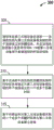
At block 305, the apparatus may receive a message from a second wireless device. The message may include wakeup information associated with the second wireless device for connection setup, and the message may include time block information indicating whether any DL-TBs are used by the second wireless device for data communication. For example, referring to fig. 2B, the second STA 254 may receive the message 256. The message 256 may include wakeup information associated with the first STA 252. The message 256 may include time block information indicating the NDL-TB used by the first STA 252 for data communication. The wake up information may have a 2 bit indicator set to 10. The time block information may indicate that the first STA 252 is using the first NDL-TB 206 and the second NDL-TB 212 for data communication.
At block 310, the apparatus may determine one or more wake-up times associated with the second wireless device for connection setup based on the wake-up information and the time block information included in the message. For example, referring to fig. 2B, based on the indicator and the time block information included in the discovery message, the second STA 254 may determine 258 an awake time associated with the first STA 252. In an example, the second STA 254 may determine that the first STA 252 is to wake up during the first and second paging windows 208, 214 of the first NDL-TB 206 and the second NDL-TB 212, respectively, and based on the indicator being set to 10, the second STA 254 may determine that the first STA 252 is to remain awake for the fixed intervals 204, 220 after the discovery windows 202, 218 for connection setup.
At block 315, the apparatus may establish a connection with the second wireless device based on the determined one or more wake-up times associated with the second wireless device. For example, referring to fig. 2B, the second STA 254 may establish a connection with the first STA 252 based on the determined wake-up times (e.g., the fixed intervals 204, 220 and the first and second paging windows 208, 214) associated with the first STA 252.
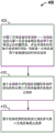
Fig. 4 is a flow diagram of an example method 400 for enabling determination of a time for setting up a data link in a NAN. The method 400 may be performed using a device, such as the STA 114, the first STA 252, or the second STA 254, for example. Although the method 400 is described below with respect to the elements of the wireless device 2302 of fig. 23 below, other components may be used to implement one or more of the steps described herein.
At block 405, the apparatus may transmit a message to a second wireless device. The message may include wakeup information associated with the first wireless device for connection setup, and the message may include time block information indicating whether any DL-TBs are used by the first wireless device for data communication. For example, referring to fig. 2B, the first STA 252 may transmit a message 256 to the second STA 254. The message 256 may include wakeup information associated with the first STA 252 for connection setup. For example, the wake up information may include a 2 bit indicator set to 10. The message 256 may include time block information indicating that a predetermined time block (e.g., the first NDL-TB 206 and the second NDL-TB 212) is used by the first STA 252 for data communication.
At block 410, the apparatus may receive a connection setup message from the second wireless device based on the wake up information and the time block information included in the message. For example, referring to fig. 2B, the first STA 252 may receive a connection setup message (e.g., an association request message) from the second STA 254 based on the indicator being set to 10 and the time block information included in the message 256. In an aspect, the association request message may be sent during the first paging window 208.
At block 410, the apparatus may establish a connection with a second wireless device based on the received connection setup message. For example, referring to fig. 2B, the first STA 252 may establish (260) a connection with the second STA 254 based on the received association request message.
The foregoing discussion has focused on methods by which a wireless device may signal wake-up times for device discovery and connection setup purposes. The following discussion focuses on methods in which wireless devices may converge on wake-up times for data transmission. In a NAN, wireless devices wishing to set up a data link need to converge on a common time to wake up. The wake-up time should be minimized to ensure power utilization. In an aspect, to establish a data link between the first STA 252 and the second STA 254, the first and second STAs 252, 254 may send availability information (e.g., a further availability map) to each other. In an aspect, connection setup and schedule negotiation (or renegotiation) for awake times may occur during an existing NDL-TB or a fixed interval (e.g., further service discovery window).
Fig. 5A is a diagram 500 with an example of availability information. The wireless devices may transmit availability information to each other to indicate when each respective wireless device is available for the data link (and, by inference, when each respective wireless device is unavailable for the data link). In an aspect, the availability information may include a schedule/bitmap. For example, a first Further Availability Map (FAM)502 represents a block of time that the first STA 252 may use to communicate data. The second FAM 504 represents a time block that the second STA 254 may use to communicate data. Referring to the first FAM 502, this example illustrates 8 time blocks in physical channel 1. In an aspect, the 8 time blocks (or any other number of timing blocks) may be within a predetermined interval. The first FAM 502 indicates that the first STA 252 is available in time blocks 1, 4, 5, and 8 in physical channel 1. The second FAM 504 indicates that the second STA 254 is available in time blocks 2, 4, 5, 7, and 8 in physical channel 1. Although diagram 500 illustrates a single FAM per STA, additional FAMs corresponding to other physical channels may be used.
To utilize the first and second FAMs 502, 504 for aggregation over a time/channel sequence for data, the first STA 252 may transmit the first FAM 502 to the second STA 254. The second STA 254 may transmit the second FAM 504 to the first STA 252. The first STA 252 may determine a group of time blocks in which both the first and second STAs 252, 254 are available. Similarly, the second STA 254 may determine a group of time blocks in which both the first and second STAs 252, 254 are available. As shown in diagram 500, the overlapping time blocks are time blocks 4, 5. As such, in establishing the P2P connection, the first and second STAs 252, 254 may determine to use time blocks 4, 5 for communication (e.g., P2P communication). In an aspect, the first and second FAMs 502, 504 may represent fields in an association request. By ensuring that a standardized algorithm is used to select the time block groups, no further messaging is required. Although this example uses only one physical channel, the first and second STAs 252, 254 may transmit FAMs associated with additional physical channels and may find commonly available time blocks across different physical channels. In an aspect, FAM may also be used to communicate availability and unavailability times for other channels (including logical channels).
However, the first and second FAMs 502, 504 only indicate when a device is available on one channel. Under the current configuration, the wireless device is unable to indicate that the wireless device is available for data exchange on any of the multiple channels. As such, the availability attribute including the FAM may be modified to include a field (or indicator) that indicates whether the device is available on any of the plurality of channels.
Fig. 5B illustrates an availability attribute 550 for determining the availability of a wireless device for scheduling a data link. The availability attribute 550 may be another example of availability information. The availability attributes 550 may include information regarding the time the device is available on a particular channel and the time the device is available on any of a plurality of channels. As shown in fig. 5B, the availability attributes 550 include an availability interval bitmap, which may correspond to the first FAM 502 or the second FAM 504. The operation class field (which may be 1 octet in size) of the availability attribute 550 indicates, for example, a frequency band that the first STA252 will be available. The channel number field (which may be 1 octet in size) indicates, for example, a physical channel that will be available to the first STA 252. The entry control field (which may be 1 octet in size) includes 8 bits of information. The first two bits of the entry control field may indicate an availability interval duration (e.g., a time block duration) associated with the availability interval. One of the remaining bits (e.g., the third bit) may be used to indicate whether the first STA252 (or any other STA) is available on all channels in the operating class. The channels in the operating class may be determined based on the geographic location of the device (e.g., on a per-country basis). For example, when the third bit is set to 1, then the first STA252 may be available on all channels in the operating class (e.g., on channels 0-7 for a specified or particular period of time). When the third bit is set to 0, then the first STA252 may be available on the channel indicated in the channel number field at the time block indicated in the bitmap. To achieve backward compatibility for STAs that are not aware of the extra bits to process in the entry control field, the channel number field may be set to one of the possible channels on which the first STA252 is available. In an aspect, one or more availability attributes may be transmitted within a message. In another aspect, the availability attribute 550 may include connectivity information associated with the first STA 252. The connectivity information may indicate a current number of active connections associated with the first STA 252. In another aspect, the availability attributes 550 may include a data link identifier (e.g., NDL ID) that identifies a data link to be negotiated and established between wireless devices. The data link identifier may enable the wireless device to refer to the data link in the event that a change to the data link is required (e.g., a scheduled change that requires the data link to be renegotiated or the data link to be deleted).
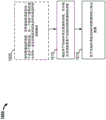
Fig. 6 is a call flow diagram 600 illustrating a first negotiated approach for paired connection setup using availability information. Referring to fig. 6, the first STA 602 and the second STA 604 may be in a NAN. The first STA 602 may transmit a first message 606 to the second STA 604 for the purpose of establishing a data link with the second STA 604. The first message 606 may include a first connectivity value and a first random number RSTA 1. The first connectivity value may be a number of active connections associated with the first STA 602. In an aspect, the first message 606 may include a data link identifier (e.g., NDL ID) identifying a data link to be negotiated and established between the first STA 602 and the second STA 604. The data link identifier enables the first STA 602 and the second STA 604 to refer to the data link in the event that a change to the data link is required (e.g., a schedule change that requires a renegotiation or will delete the data link).
The second STA 604 may transmit a second message 608 to the first STA 602. The second message 608 may include a second connectivity value and a second random number. The second connectivity value may be a number of active connections associated with the second STA 604. Having received the connectivity value and the random number for each other, the first STA 602 or the second STA 604 may determine whether to transmit the availability information (e.g., the availability attribute 550) based on a comparison of the first connectivity value and the second connectivity value. In an aspect, wireless devices with larger connectivity values (e.g., more connections) transmit availability information for use in determining a schedule for a data link, as wireless devices with more connections may have more restrictions on time availability. In another aspect, wireless devices with smaller connectivity values may transmit availability information for use in determining a schedule. In an aspect, if the first and second connectivity values are the same, the first random number RSTA1 and the second random number RSTA2 may be used as a tiebreaker to determine which device transmits availability information. For example, in the case of a tie in the number of connections between devices, a wireless device with a larger random number may transmit availability information. Referring to fig. 6, if the first connectivity value is greater than the second connectivity value, the first STA 602 may transmit availability information 610 (e.g., availability attributes 550) associated with the first STA 602 to the second STA 604. Otherwise, if the first connectivity value is less than the second connectivity value, the second STA 604 may send availability information 610 (example not shown). In the case where the connectivity value is a tie, the first and second random numbers RSTA1, RSTA2 may be used as the tiebreaker. Assuming that the first STA 602 has a greater connectivity value than the second STA 604, upon receiving the availability information 610, the second STA 604 may determine (612) a schedule to be used for data communication based on the availability information 610. The second STA 604 may select from the availability time block schedule provided by the first STA 602 in the availability information. As discussed in fig. 5B, the availability information 610 may indicate one or more time blocks (e.g., schedules) for which the first STA 602 is available on a channel and an indicator indicating whether the first STA 602 is available on any channel of a set of channels. Based on the received availability information 610, the second STA 604 may choose one or more available time blocks associated with the first STA 602 based on whether any of the time blocks associated with the first STA 602 correspond to available time blocks associated with the second STA 604. If none of the time blocks/channels associated with the first STA 602 in the availability information 610 are suitable for the second STA 604, the second STA 604 may send a message to the first STA 602 indicating that the NDL setup has failed. Otherwise, if the second STA 604 identifies one or more time blocks that are available to both the first STA 602 and the second STA 604, the second STA 604 may determine (612) an NDL schedule 614 and transmit the NDL schedule 614 to the first STA 602. In one configuration, the first STA 602 may optionally transmit a schedule confirmation message 616 to the second STA 604. The schedule confirmation message 616 may indicate (e.g., using a confirmation bit) that the first STA 602 accepts the NDL schedule 614 proposed by the second STA 604, is ready to receive data from the second STA 604, and/or is ready to transmit data to the second STA 604. In an aspect, the first STA 602 may send the schedule confirmation message 616 after the first STA 602 has set up resources (e.g., buffers and state machines) for communication over the data link. In another aspect, the second STA 604 may not transmit data on the NDL schedule 614 until the second STA 604 receives the schedule confirmation message 616. Subsequently, after the first STA 602 transmits the schedule confirmation message 616, the first STA 602 and the second STA 604 may establish a data link 618 (e.g., a P2P connection) based on the NDL schedule 614. In another configuration, the first STA 602 may not transmit the schedule confirmation message 616 and the second STA 604 may begin communicating over the data link 618 after transmitting the NDL schedule 614. However, the first STA 602 may not be ready to receive data, and thus, in some instances, utilizing the schedule confirmation message 616 may prevent a situation in which the first STA 602 receives a message on the data link 618 before being ready.
In another aspect, the NDL (e.g., data link 618) may be associated with a lifetime (or validity time). The lifetime may be a value indicating when NDL will expire. The NDL lifetime may be declared in the NAN as part of the NDL attribute. The lifetime may provide a clear boundary as to when a wireless device may switch to a different NDL or NDL schedule (if desired). Since the wireless devices within the NAN are synchronized and the lifetime is announced within the NAN, all wireless devices may have the same understanding of when the lifetime epoch occurs. The lifetime may also provide a time when the main transition will occur. For example, the lifetime may end when a common group key (e.g., used to encrypt any group-addressed traffic) is updated or when one or more devices of the NDL move to a different cluster. Initially, the NDL lifetime may be set by the creator of the NDL and may be extended by any wireless device using the NDL. The wireless device that extends the lifetime may be the same wireless device that initiated the NDL or a different device. For example, in a one-to-many wireless device topology, service provider devices may extend lifetime. In one-to-one or many-to-many topologies, however, a service provider or subscriber may extend the life of the NDL. If the NDL is no longer needed (e.g., no more data is left to send), the lifetime may not be extended and all wireless devices may leave the NDL at the expiration of the lifetime. However, if one or more wireless devices have additional data to send or receive in the NDL, the one or more wireless devices may extend the lifetime of the NDL. Thus, in an aspect, referring to fig. 6, if the second STA 604 determines that the NDL setup has failed, the first and second STAs 602, 604 may decide to use a predetermined scheduling scheme (e.g., a non-negotiated scheduling scheme, such as a NDL profile-based schedule, a default NDL schedule, or a service provider NDL schedule) for data communication. The predetermined scheduling scheme may be used to establish an NDL associated with a lifetime. Once the lifetime expires, the second STA 604 (or the first STA 602) may attempt to renegotiate the NDL schedule after the lifetime expires in the event that any conditions have changed (e.g., the first STA 602 and/or the second STA 604 have more availability due to one or more connections no longer being active). The extension of NDL may be similar to the new NDL scheduling negotiation. The new schedule negotiation occurs outside of the DW and may occur during the existing NDL-TB, FSD, or some other commonly agreed-upon time.
Fig. 7A is a call flow diagram 700 illustrating a first variant of a second negotiated approach for paired connection setup using availability information. Referring to fig. 7A, a first STA 702 and a second STA 704 are in a NAN. The first STA 702 transmits first availability information 706 (e.g., a first availability attribute) to the second STA 704. The second STA 704 transmits second availability information 708 (e.g., a second availability attribute) to the first STA 702. The first STA 702 combines the received second availability information 708 with the first availability information 706 to determine (710) a mutual schedule based on a standardized or accepted algorithm. Similarly, the second STA 704 combines the received first availability information 706 with the second availability information 708 to determine (712) the same mutual schedule as determined by the first STA 702 using the same standardized/accepted algorithm. In an aspect, the algorithm may be based on common criteria as to how subsets of overlapping time blocks will be selected given one or more quality of service requirements. Further, the algorithm may be based on a common set of criteria for choosing a channel when a group of channels is available at a particular time. In an example, when a group of channels is available, the devices may determine which channel has the lowest energy usage level, which would imply that the channel is less congested with traffic from other devices. In one configuration, after determining the mutual schedule, the first STA 702 may optionally transmit a schedule confirmation message 714 to the second STA 704. The schedule confirmation message 714 may indicate (e.g., using a confirmation bit) that the first STA 702 is ready to receive data according to the determined mutual schedule and/or is ready to transmit data according to the determined mutual schedule. In an aspect, the first STA 702 may send the schedule confirmation message 714 after the first STA 702 has set up resources (e.g., buffers and state machines) for communication over the data link. In another aspect, the second STA 704 may not transmit data on the mutual schedule until the second STA 704 receives the schedule confirmation message 714 from the first STA 702. Subsequently, after the first STA 702 transmits the schedule confirmation message 714, the first STA 702 and the second STA 704 may establish a data link 716 (e.g., a P2P connection) based on the determined mutual schedule. In another configuration, the first STA 702 may not transmit the schedule confirmation message 714 and the second STA 704 may begin communicating over the data link 716 after determining the mutual schedule. However, the first STA 702 may not be ready to receive data, and thus, in some instances, utilizing the schedule confirmation message 714 may prevent a situation in which the first STA 702 receives data on the data link 716 before being ready. In another aspect, the first STA 702 and/or the second STA 704 may re-evaluate the determined mutual schedule after a lifetime associated with the data link 716 has expired. The re-evaluation may be based on whether any conditions have changed (e.g., whether any data remains to be sent, whether quality of service requirements have changed, etc.).
Fig. 7B is a call flow diagram 750 illustrating a second variation of the second negotiated approach for pair-wise connection setup using availability information. Referring to fig. 7B, the first STA 752 and the second STA 754 are in a NAN. The first STA 752 transmits first availability information 756 (e.g., a first availability attribute) to the second STA 754. The first availability information may include a first schedule at which the first STA 752 is available on the first channel (e.g., an availability interval bitmap as shown in fig. 5B), and a first channel indicator indicating whether the first STA 752 is available on any channel of the set of channels (e.g., a bit indicator indicating that the first STA 752 is available in all channels in the operating class as shown in fig. 5B).
Upon receiving the first availability information 756, the second STA 754 may determine whether the second STA 754 is available during most or all of the time indicated in the first availability information. The second STA 754 may determine second availability information 758 (e.g., a second availability attribute) to transmit to the first STA 752 based on the first availability information 756. In one aspect, if the second STA 754 is available during all of the time indicated in the first availability information, the second STA 754 may determine to communicate with the first STA 752 using the same schedule indicated in the first availability information. As such, the second availability information 758 may have a second schedule that is the same as the first schedule and a second indicator that is the same as the first indicator. On the other hand, if the second STA 754 is available during most of the time indicated in the first availability information, the second STA 754 may determine a second schedule that includes time during which both the first and second STAs 752, 754 are available. The second schedule may include additional time during which the second STA 754 is available. On the other hand, if the second STA 754 is unavailable during any or most of the time indicated in the first availability information 756, the second STA 754 may determine a second schedule that may be mostly different from the first schedule. The second STA 754 may transmit the second availability information 758 to the first STA 752. In an aspect, the second availability information may include a second indicator indicating whether the second STA 754 is available on any channel of the set of channels. The first STA 752 may determine whether the first STA 752 is available during most or all of the time indicated in the second availability information 758. If not, the first STA 752 and the second STA 754 may proceed to negotiate a mutually agreed schedule by transmitting additional availability information. In an aspect, after the first and second STAs 752, 754 make a predetermined number of availability information exchanges (e.g., 10-round exchanges), the negotiation may fail and the first and second STAs 752, 754 may determine to stop the negotiation.
After determining the mutually agreed schedule, the first STA 752 may optionally transmit a schedule confirmation message 760 to the second STA 754. The schedule confirmation message 760 may indicate (e.g., using a confirmation bit) that the first STA 752 is ready to receive data according to the determined mutual schedule and/or is ready to transmit data according to the determined mutual schedule. In an aspect, the first STA 752 may send the schedule confirmation message 760 after the first STA 752 has set up resources (e.g., buffers and state machines) for communicating over the data link. In another aspect, the second STA 754 may not transmit data on the mutual schedule until the second STA 754 receives the schedule confirmation message 760 from the first STA 752. Subsequently, after the first STA 752 transmits the schedule confirmation message 760, the first STA 752 and the second STA 754 may establish a data link 762 (e.g., a P2P connection) based on the determined mutual schedule. In another configuration, the first STA 752 may not transmit the schedule confirmation message 760 and the second STA 754 may begin communicating over the data link 762 after determining the mutual schedule. However, the first STA 752 may not be ready to receive data, and thus, in some examples, utilizing the schedule confirmation message 760 may prevent a situation in which the first STA 752 receives a message on the data link 762 before being ready. In another aspect, the first STA 752 and/or the second STA 754 may re-evaluate the determined mutual schedule after a lifetime associated with the data link 762 has expired. The re-evaluation may be based on whether any conditions have changed (e.g., whether any data remains to be sent, whether quality of service requirements have changed, etc.).
In an aspect, instead of or in addition to indicating a time (e.g., a preferred time and/or a preferred channel) that a device may be available for NDL, the device may indicate an unavailability time as part of a scheduling negotiation. The unavailability time may be an NDL-TB and/or an unavailable channel. An indication of an unavailability time may be useful when a device wishes to avoid such blocks of time because the device is busy (e.g., has other concurrent networks or has some other activity) and does not wish to have any NDL operations during certain times. Examples of concurrent networks may be other NDLs, intra-AP connections, bluetooth, etc. Similarly, in some instances, the device may indicate the preferred channel due to ongoing operation on the channel. A device may prefer to use a channel to avoid channel switching. In another aspect, the device may avoid certain channels, for example, because these channels are known to have LTE and/or other deployments.
Negotiated scheduling has been discussed in fig. 6, 7A and 7B with respect to one-to-one connections. However, in some instances, a one-to-many connection may be desirable. For example, a first wireless device may have a photo to be shared with many wireless devices. In the simplest case, the first wireless device may set up a data link with each of these other wireless devices on a pair-wise basis. But this may result in the first wireless device waking up too long to accommodate multiple wakeup schedules. Furthermore, the order in which the connections are set up may make it impossible to include some destinations. For example, a first wireless device may set up a connection with second and third wireless devices. Subsequently, the fourth wireless device may wish to set up a connection, but since the second and third wireless devices used all available time blocks associated with the first wireless device, there may be no more time blocks left from the first wireless device. An alternative for one-to-many connection setup is shown in fig. 8.
Fig. 8 is a call flow diagram 800 illustrating a third negotiated approach for performing one-to-many connection setup based on availability information. Referring to fig. 8, the first STA 802 may send a setup solicitation message 810 (e.g., a NAN data link setup solicitation message) to the second STA 804, the third STA 806, and the fourth STA 808. The setup solicitation message 810 may indicate a request to receive availability information (e.g., availability attributes 550). Upon receiving the setup solicitation message 810, the second STA 804 may transmit first availability information 812 (e.g., availability attributes 550) to the first STA 802. The third STA 806 may transmit second availability information 814 to the first STA 802. The fourth STA 808 may transmit the third availability information 816 to the first STA 802. The first, second, and third availability information 812, 814, 816 may be availability attributes (e.g., FAMs that include the availability of STAs on a particular channel and/or the availability of STAs on any channel in a set of channels). In an aspect, the first, second and third availability information 812, 814, 816 may include current connectivity information associated with each STA, respectively. Upon receiving the first, second, and third availability information 812, 814, 816, the first STA 802 may determine 818 a schedule 820 or a set of times to communicate data with each of the second, third, and fourth STAs 804, 806, 808. The schedule 820 may be determined based on a time in which both the first STA 802 and the other STAs (e.g., the second STA 804, the third STA 806, and the fourth STA 808) are available. The scheduling 820 may be further based on throughput requirements, quality of service requirements, and/or physical channel conditions. . In another aspect, the first STA 802 may determine 818 a schedule 820 based on connectivity information that may be included in the first, second, and/or third availability information 812, 814, 816. In this regard, the first STA 802 may consider the schedule of restricted devices (e.g., devices with a large number of active connections when determining the schedule 820). The schedule 820 may include one or more NDL-TBs allocated to or associated with each of the second STA 804, the third STA 806, and the fourth STA 808 for P2P communication within the NAN. In an aspect, the first STA 802 may send the same schedule 820 to each of the second, third, and fourth STAs 804, 806, 808. In another aspect, the first STA 802 may send a different schedule 820 to each of the second, third, and fourth STAs 804, 806, 808. Upon receiving the schedule 820, the first STA 802 may establish a first data link 822 with the second STA 804. The first STA 802 may establish a second data link 824 with the third STA 806. The first STA 802 may establish a third data link 826 with the fourth STA 808. Each of the first, second and third data links 822, 824, 826 may be a P2P connection.
In an aspect, similar to the discussion with respect to fig. 6, 7A, and 7B, the second STA 804, the third STA 806, and/or the fourth STA 808 may transmit the schedule confirmation message upon receiving the schedule 820 from the first STA 802. The first STA 802 may not transmit data based on the schedule 820 until the first STA 802 receives a schedule confirmation from at least one of the first, second, or third STAs 802, 804, 806.
In another aspect, the first, second, and third data links 822, 824, 826 can each be associated with a respective lifetime. At or before the expiration of the lifetime, the first STA 802, the second STA 804, the third STA 806, and/or the fourth STA 808 may re-evaluate the schedule 820 or the corresponding data link based on any condition changes (e.g., no more data left to transmit/receive, a quality of service or latency requirement change, a number of devices in the NAN change, a power change of the devices, etc.) and determine whether to extend the corresponding lifetime of the data link or leave the data link.
Fig. 6, 7A, 7B, and 8 relate to methods for negotiating connection setup and connection setup parameters (e.g., NDL-TB). In some circumstances, it may not be possible to accommodate different schedules for several STAs in a single schedule, especially if the STAs are available on different channels and would require that the STA providing the service switch between different channels. Furthermore, as discussed previously, the order in which the STAs are considered affects the resulting schedule. To create a schedule that accommodates both STAs, the schedule that has been set up with one of these STAs may have to be changed. It may be difficult to quickly change the established schedule when additional STAs request connection setup. In other words, the mutually negotiated data transfer times may not scale for a large number of wireless devices. As such, noncommercial (or predetermined) scheduling may also be used, particularly in one-to-many or many-to-many topologies.
Fig. 9 is a call flow diagram 900 illustrating a non-negotiated approach for using service provider scheduling with standardized periodic time blocks for data links. Instead of allowing each STA requesting a data connection to negotiate a time block based on an availability attribute, for example, the first STA 902 providing the service may utilize a service provider NDL schedule. The second STA 904, the third STA 906, and the fourth STA 908 may be interested in receiving/joining the service provided by the first STA 902. Referring to fig. 9, the first STA 902 may determine (910) a service provider NDL schedule 912 for providing the service. In an aspect, the service provider NDL schedule 912 may be published by the first STA 902 when the first STA 902 announces one or more services (e.g., in a discovery window that is part of NAN service discovery). In this regard, the service provider NDL schedule 912 may be inserted into an NDL attribute within, for example, a service discovery frame.
In another aspect, the NDL attribute may be inserted into a NAN Management Frame (NMF). The NMF may have the same or similar structure as the service discovery frame. The NMF may carry attributes related to NAN operation. In an aspect, NMF may be used for post-service discovery operations, such as NDL or NDP schedule negotiation. In some examples, the NMF may be transmitted via a NAN interface rather than an NDL interface for some types of messages. For example, the NAN interface may be used for NAN control signaling, such as NAN discovery and/or connection setup. As such, all NMFs related to the previous NDL may be transmitted over the NAN interface, as the NDL interface has not been set up. Subsequently, when NDL is set up, an NDL interface (or an NDP interface) may be used for data transmission over NDP. As such, after NDL is set up, the NDL interface may be used to transmit the NMF associated with the NDL. In such cases, the receiver device may have a mapping between the NAN interface and the NDL interface of its NDL peer. In another aspect, the NMF may be a vendor specific action frame or a vendor specific public action frame. By having NAN and NDL interfaces, the design may be more defined — that is, once NDL is established, all NDL activities (data and management) may occur on the NDL interface.
In an aspect, there may be only one NDL between two wireless devices. However, multiple NDPs may exist between two devices, and each NDP may be associated with a particular service. The NDP may also be associated with an NDP ID to map a particular session between two devices. The NDP may have its own quality of service and/or security requirements. Each NDP may also have its own interface. Between two wireless devices, all NDPs between the two wireless devices may follow the same schedule, which may be an NDL schedule between the two devices. The NDL ID may be an identifier assigned to an NDL between devices. The NDL ID may be represented in a bitmap for traffic announcement, e.g., during a paging window. That is, one or more locations in the bitmap may correspond to an NDL ID. When the bit corresponding to the NDL is set to 1, then traffic associated with the NDL ID is upcoming. Conversely, when the bit corresponding to the NDL is set to 0, no traffic associated with the NDL ID is expected. Such traffic signaling may be useful when multiple wireless devices associated with different NDLs have the same or similar wake-up times. Although the wireless devices are awake during some same time, the wireless devices may go to sleep when the NDL IDs to which the wireless devices are subscribed are not signaled in a bitmap during a traffic announcement period (e.g., paging window).
In another aspect, the service provider NDL schedule 912 may indicate one or more logical channels for a network data link connection (e.g., a P2P connection). Each logical channel in the service provider NDL schedule 912 may include a set of time blocks (e.g., NDL-TBs) having a particular time block duration (e.g., 15ms) and a particular time block periodicity (e.g., every 75 ms). In an aspect, different logical channels in the service provider NDL schedule 912 may reference different time blocks having different time block durations and/or having different periodicities. The time block duration and periodicity may be determined based on quality of service, throughput requirements, and the like. As such, devices requiring higher throughput (e.g., the second STA 904, the third STA 906, or the fourth STA 908) may select an appropriate logical channel. In an aspect, devices interested in the service may join the service provider NDL schedule 912 if the devices are available for a majority of the NDL schedule 912. For example, if devices are available for more than x% of the service provider NDL schedule 912, then these devices may be available for a majority of the service provider NDL schedule 912, where x% may be 60%, 80%, or 90%. In an aspect, x% may be a function of the type of service being provided (e.g., latency and/or throughput requirements associated with the type of service).
Referring to fig. 9, the service provider NDL schedule 912 may have 5 different logical channels (or any other number of logical channels). Each of these logical channels may be associated with a different set of time blocks having a different time block duration and/or periodicity. Upon receiving the service provider NDL schedule 912, the second STA 904, the third STA 906, and the fourth STA 908 may select one of these logical channels for setting up a data link with the first STA 902. In an aspect, each of the second STA 904, the third STA 906, or the fourth STA 908 may select a physical channel to be used for the selected logical channel. The physical channel may be selected based on the amount of energy detected on that channel. Based on the selected logical/physical channel, the second STA 904 may establish a first data link 914 with the first STA 902, the third STA 906 may establish a second data link 916 with the first STA 902, and the fourth STA 908 may establish a third data link 918 with the first STA 902. In an aspect, the first, second, and third data links 914, 916, 918 may be associated with respective lifetimes that indicate when each of these data links expires and/or begins.
Fig. 10 is a call flow diagram 1000 illustrating a non-negotiated approach for determining a schedule for a data link using a profile associated with a service. Profile-based scheduling is applicable to any topology. Similar to the method discussed in fig. 9, fig. 10 relates to a method for establishing a data link schedule without negotiation between wireless devices. In this approach, the data link schedule may be customized based on the type of application/service being advertised. Referring to fig. 10, the first STA 1002 may have various services, where each service may have different latency and/or throughput requirements. In an aspect, the first STA 1002 may determine (1010) an NDL profile based on the service. In an aspect, various NDL profiles may be customized to meet certain service requirements (e.g., latency, throughput, power, topology, etc.). Each NDL profile may map to a set of NDL schedules that may be customized to meet the requirements of a service or application. Applications or services may be classified into groups, and each group may be associated with a particular NDL profile. For example, voice chats may be classified into one group (e.g., a small block of time that repeats frequently), video chats may be classified into a different group (e.g., a long block of time that repeats frequently), and file transfers may be classified into yet another different group (e.g., a long block of time that repeats infrequently) based on service requirements. When the first STA 1002 has a service to announce, the first STA 1002 may determine (1010) an NDL profile associated with the service. Based on the NDL profile, the first STA 1002 may determine a set of schedules associated with the NDL profile. In an aspect, the first STA 1002 may select an NDL profile based schedule 1012 based on the set of schedules and transmit the NDL profile based schedule 1012 to the second STA 1004, the third STA 1006, and/or the fourth STA 1008. In another aspect, the NDL profile-based schedule 1012 may include a subset of a schedule selected from a set of schedules associated with the NDL profile, and the first STA 1002 may transmit the subset of the schedule to the second STA 1004, the third STA 1006, and/or the fourth STA 1008. In another aspect, each type of schedule may be associated with an index. In this regard, the first STA 1002 may transmit an NDL profile based schedule 1012, which may include the NDL profile and/or one or more indices associated with different NDL schedules. Upon receiving the NDL profile based schedule 1012, the second, third, and fourth STAs 1004, 1006, 1008 may converge on mutually acceptable schedules and establish a first data link 1014, a second data link 1016, and a third data link 1018, respectively, with the first STA 1002. In an aspect, the first, second, and third data links 1014, 1016, 1018 may each be associated with a respective lifetime.
Fig. 11 is a call flow diagram 1100 illustrating a non-negotiated approach for using default NDL scheduling for a data link. The default NDL schedule may be suitable for a many-to-many topology where the availability of multiple wireless devices may be difficult to accommodate. Each NAN cluster may have a default NDL schedule that any service announced on that NAN may utilize. The default NDL schedule may be defined by an anchor master associated with the NAN cluster, an initiator of the NAN cluster, or other members of the NAN on a round-robin basis. The initiator of the NAN is the first wireless device that decides to create the NAN by sending out a beacon, e.g., announcing the NAN. The anchor master associated with the NAN cluster may be an initiator of the NAN or another wireless device within the NAN. The anchor master may be responsible for issuing beacon messages announcing the NAN. In an aspect, the anchor master may choose based on an amount of available resources (e.g., battery power, connectivity, geographic proximity with other wireless devices within the NAN) associated with the wireless device compared to other wireless devices in the NAN. Referring to fig. 11, a first STA 1102 may have a service to be announced. In an aspect, the first STA 1102 may determine (1110) a default NDL schedule 1112 for the service based on a default NDL schedule advertised by wireless devices within the NAN. In another aspect, the first STA 1102 may be a wireless device responsible for determining a default NDL schedule. Wireless devices interested in the service (e.g., the second STA 1104, the third STA 1106, and/or the fourth STA 1108) may join the default NDL to begin data exchange. In an aspect, the second STA 1104 may further negotiate a new or supplemental NDL schedule if the default NDL schedule does not meet application requirements. For example, in a first scenario, the second STA 1104 may immediately determine that the default NDL schedule is insufficient. In this scenario, the second STA 1104 may negotiate a supplemental NDL schedule (e.g., by using the NDL-TB of the default NDL schedule if the first STA 1102 wakes up during a paging window of the NDL-TB of the default NDL schedule). In a second scenario, the second STA 1104 may utilize the default NDL schedule for a period of time and then determine that the default NDL schedule is no longer sufficient based on additional users joining the schedule or other factors. In this scenario, the second STA 1104 may negotiate a supplemental NDL schedule. In a third scenario, the second STA 1104 may negotiate a new NDL schedule based on service requirements without using a default NDL schedule. In an aspect, the second STA 1104 may utilize the NDL-TB in a default NDL schedule for connection setup. In this regard, the second STA 1104 need not exchange user data using the NDL-TB in the default NDL schedule. Instead, the second STA 1104 may utilize a paging window within the NDL-TB to perform connection setup for a service of interest to the second STA 1104. In other words, negotiating a new or supplemental data link may occur on a default NDL schedule.
Fig. 12 is a call flow diagram 1200 illustrating a hybrid approach for using predetermined NDL scheduling and negotiated NDL scheduling for a data link. In one configuration, the first STA 1202 may utilize both the predetermined NDL schedule (non-negotiable) discussed in fig. 9-11 and the negotiated NDL schedule discussed in fig. 6-8. For example, during most peer-to-peer type short connection setup and teardown, the first STA 1202 may use the negotiated approach in fig. 6, 7A, 7B, or 8. In one-to-many or many-to-many connections, the first STA 1202 may use a predetermined NDL schedule. As an example, referring to fig. 12 illustrating a one-to-many connection, the first STA 1202 may initially determine (1210) a predetermined NDL schedule 1212 (e.g., a service provider NDL schedule 912, an NDL profile-based schedule 1012, or a default NDL schedule 1112). Based on the predetermined NDL schedule 1212, the first STA 1202 may establish a first data link 1214 with the second STA 1204, a second data link 1216 with the third STA 1206, and a third data link 1218 with the fourth STA 1208.
Subsequently, in one configuration, the first STA 1202 may determine (1220) that the predetermined NDL schedule 1212 no longer satisfies one or more requirements for communicating data associated with the service, or may determine (1220) that a change in the number of wireless devices in the NAN or a change in service topology has occurred. In an aspect, the one or more requirements may include a latency requirement of the service or wireless device, a throughput requirement of the service or wireless device, or a power requirement of the service or wireless device. In another configuration, the first STA 1202 may determine (1220), based on the message 1222 from the first STA 1202, that the predetermined NDL schedule 1212 no longer satisfies one or more requirements for communicating data associated with the service. The message 1222 may indicate that the predetermined NDL schedule 1212 no longer satisfies one or more requirements for communicating data associated with the service. Message 1222 may request additional resources for data communication. The message 1222 may include availability information (e.g., availability attributes) associated with the second STA 1204. In an aspect, the first STA 1202 and the second STA 1204 may negotiate different NDL schedules 1224 on the predetermined NDL schedule 1212. Based on the received message 1222, the first STA 1202 may determine a different NDL schedule 1224 to use for communicating in the new/supplemental data link 1226 with the second STA 1204. In an aspect, if the different NDL schedule 1224 is for a new data link, the first and second STAs 1202, 1204 may continue to communicate on the first data link 1214 until the lifetime associated with the first data link 1214 has expired, at which time the first and second STAs 1202, 1204 may establish the new data link for communication. In an aspect, the lifetime of the first data link 1214 may be shortened based on a determination that the predetermined NDL schedule 1212 no longer meets requirements. On the other hand, if the different NDL schedule 1224 is for a supplemental data link, the first and second STAs 1202, 1204 may continue to communicate on the first data link 1214 until the lifetime associated with the first data link 1214 has expired, and also communicate on the supplemental data link.
Fig. 13A is a flow diagram of an example method 1300 of a service recipient performing a first negotiated approach for pair-wise connection setup using availability information. The method 1300 may be performed using an apparatus (e.g., the STA 114, the second STA 604, or the wireless device 2302, below, for example). Although the method 1300 is described below with respect to the elements of the wireless device 2302 of fig. 23 below, other components may be used to implement one or more of the steps described herein.
At block 1305, the apparatus may transmit a first message to a second wireless device. The first message may include a first connectivity value and a first random number. For example, referring to fig. 6, the second STA 604 may transmit a second message 608 to the first STA 602. The second message 608 may include a second connectivity value and a second random number.
At block 1310, the apparatus may receive a second message from a second wireless device. The second message may include a second connectivity value and a second random number. In an aspect, the first connectivity value may be associated with a first number of active connections associated with the apparatus and the second connectivity value is associated with a second number of active connections associated with the second wireless device. For example, referring to fig. 6, the second STA 604 may receive the first message 606 from the first STA 602. The first message 606 may include a first connectivity value and a first random number. The first connectivity value may be associated with a first number of active connections associated with the first STA 602, and the second connectivity value may be associated with a second number of active connections associated with the second STA 604.
At block 1315, the apparatus may determine whether to transmit the availability information based on a comparison of the first connectivity value and the second connectivity value. In an aspect, the apparatus determines to transmit the availability information if the first connectivity value is greater than the second connectivity value, and the wireless device determines not to transmit the availability information if the first connectivity value is less than the second connectivity value. In another aspect, determining whether to transmit the availability information may also be based on a comparison of the first random number and the second random number. For example, referring to fig. 6, because the first connectivity value is greater than the second connectivity value, the second STA 604 may determine not to transmit availability information to the first STA 602.
At block 1320, the apparatus may receive availability information from the second wireless device. The availability information may include a schedule in which the second wireless device is available on a channel and an indicator indicating whether the second wireless device is available on any channel of a set of channels. For example, referring to fig. 6, the second STA 604 may receive availability information from the first STA 602. The availability information may include a FAM indicating a time in which the first STA 602 is available as in fig. 5B.
At block 1325, the apparatus may determine a schedule for communicating data in a NAN. For example, referring to fig. 6, the second STA 604 may determine a schedule for communicating data with the first STA 602 in a NAN. The second STA 604 may determine the schedule by determining a time at which the second STA 604 is available and determining when the first STA 602 and the second STA 604 have overlapping availability based on the determined time. The determined schedule may include overlapping times. The determined schedule may also include additional time during which the second STA 604 is available.
At block 1330, the apparatus may transmit the determined schedule for communicating data over the P2P connection. The determined schedule may be based on the received availability information. For example, referring to fig. 6, the second STA 604 may transmit the determined schedule to the first STA 602 for communicating data over the P2P connection.
At block 1335, the apparatus may communicate data over a data link within the NAN based on the determined schedule. For example, referring to fig. 6, the second STA 604 may communicate data with the first STA 602 over the data link 618 based on the determined schedule.
Fig. 13B is a flow diagram of an exemplary method 1350 in which a wireless device performs a first variant of the second negotiated approach for pair-wise connection setup using availability information. The method 1350 may be performed using a device (e.g., the STA 114, the first STA 752, or the wireless device 2302, below, for example). Although the method 1350 is described below with respect to the elements of the wireless device 2302 of fig. 23, below, other components may be used to implement one or more of the steps described herein.
At block 1355, the apparatus may transmit the first availability information to the second wireless device. The first availability information may include a first schedule at which the apparatus is available on a first channel and a first indicator indicating whether the apparatus is available on any channel of a set of channels. For example, referring to fig. 7B, the first STA 752 may transmit the first availability information 756 to the second STA 754. The first availability information 756 may include a first schedule at which the first STA 752 is available on the first channel and a first indicator indicating whether the first STA 752 is available on any channel of the set of channels.
At block 1360, the apparatus may receive second availability information from the second wireless device based on the transmitted first availability information. The second availability information may include a second schedule at which the second wireless device is available on the second channel and a second indicator indicating whether the second wireless device is available on any channel of the set of channels. In one aspect, the second schedule may be the same as the first schedule. In another aspect, the second schedule may be different from the first schedule. For example, referring to fig. 7B, the first STA 752 may be configured to receive the second availability information 758 from the second STA 754 based on the transmitted first availability information 756. Since both the first STA 752 and the second STA 754 are available during the same time, the second availability information 758 may include the same schedule as the first availability information 756.
At block 1365, the apparatus may determine a schedule for communicating data in a NAN. In an aspect, the schedule may be determined based on the transmitted first availability information and the received second availability information. In one configuration, the apparatus may determine the schedule by determining that the apparatus is unavailable during the second schedule and by transmitting third availability information to the second wireless device to further negotiate a mutually agreed schedule. The third availability information may include a third schedule and a third indicator. In an aspect, the third schedule and/or the third indicator may be based on the received second availability information. For example, referring to fig. 7B, the first STA 752 may determine a schedule for communicating data in a NAN. The first STA 752 may determine that the schedule indicated in the second availability information 758 is the same as the schedule indicated in the first availability information 756. Accordingly, the first STA 752 may determine that the communication schedule is the same as the schedule indicated in the first and second availability information 756, 758. However, if the schedules are different, the first STA 752 may determine a new schedule to transmit to the second STA 754, and the new schedule may be based on the availability time indicated in the second availability information 758.
At block 1370, the apparatus may transmit a scheduling confirmation message indicating that the apparatus is available for communication based on the received second availability information. The schedule for the data link within the NAN may be based on the received second availability information. Referring to fig. 7B, the first STA 752 may transmit a schedule confirmation message 760 indicating that the first STA 752 is available for communication based on the received second availability information 758.
At block 1375, the apparatus may communicate data over a data link within the NAN based on the determined schedule. In an aspect, the communication may occur after the apparatus transmits a scheduling acknowledgement message. For example, referring to fig. 7B, the second STA 754 may communicate data over the data link 718 based on the determined schedule.
Fig. 14 is a flow diagram of an exemplary method 1400 for a service recipient/provider to perform a second negotiated approach for pair-wise connection setup using availability information. The method 1400 may be performed using an apparatus (e.g., the STA 114, the second STA 704, or the wireless device 2302, below, for example). Although the method 1400 is described below with respect to the elements of the wireless device 2302 of fig. 23, below, other components may be used to implement one or more of the steps described herein.
At block 1405, the apparatus may transmit first availability information to a second wireless device. The first availability information may include a first schedule at which the apparatus is available on a first channel and a first indicator indicating whether the apparatus is available on any channel of a set of channels.
At block 1410, the apparatus may receive second availability information from a second wireless device. The second availability information may include a second schedule at which the second wireless device is available on the second channel and a second indicator indicating whether the second wireless device is available on any channel of the set of channels.
At block 1415, the apparatus may determine a schedule for communicating data in a NAN. In an aspect, determining a schedule for communicating data may be based on a common set of criteria known to the apparatus and the second wireless device, and the common set of criteria may include a quality of service requirement or an energy usage level.
At block 1420, the apparatus may communicate data over a data link within the NAN based on the determined schedule.
Fig. 15 is a flow diagram of an exemplary method 1500 by which a service recipient performs a third negotiated approach for performing one-to-many connection setup based on availability information. The method 1500 may be performed using an apparatus (e.g., the STA 114, the second STA 804, or the wireless device 2302, below, for example). Although the method 1500 is described below with respect to the elements of the wireless device 2302 of fig. 23 below, other components may be used to implement one or more of the steps described herein.
In block 1505, the device may receive a data link setup solicitation message. For example, referring to fig. 8, the second STA 804 may receive the setup solicitation message 810.
At block 1510, the apparatus may transmit availability information to the second wireless device. The availability information may include a first schedule at which the apparatus is available on a channel and an indicator indicating whether the apparatus is available on any channel of a set of channels, and the availability information may be transmitted based on the received data link setup solicitation message. For example, referring to fig. 8, the second STA 804 may transmit first availability information 812 to the first STA 802. The first availability information 812 may include a first schedule (e.g., FAM) in which the second STA 804 is available on a channel and an indicator indicating whether the second STA 804 is available on any channel of the set of channels.
At block 1515, the apparatus may receive a data link schedule based on the transmitted availability information. For example, referring to fig. 8, the second STA 804 may receive the schedule 820 based on the transmitted first availability information 812.
At block 1520, the apparatus may determine a schedule for communicating data in a NAN, wherein the schedule is determined based on the received data link schedule. For example, referring to fig. 8, the second STA 804 may determine a schedule for communicating data. The schedule is determined by extracting the scheduling information from the schedule 820 and by storing the scheduling information from the schedule 820. The second STA 804 may determine whether the second STA 804 is available on the received schedule 820. If so, the second STA 804 may determine to communicate using the received second schedule 820.
At block 1525, the apparatus may communicate data over a data link within the NAN based on the determined schedule. For example, referring to fig. 8, the second STA 804 may communicate data over the first data link 822 based on the determined schedule.
Fig. 16 is a flow diagram of an exemplary method 1600 for a service recipient to perform a non-negotiated approach for using a service provider schedule with standardized periodic time blocks for a data link. The method 1600 may be performed using an apparatus (e.g., the STA 114, the second STA 904, or the wireless device 2302, below, for example). Although the method 1600 is described below with respect to the elements of the wireless device 2302 of fig. 23 below, other components may be used to implement one or more of the steps described herein.
At block 1605, the apparatus may receive a data link schedule, and the data link schedule may include one or more logical channels. Each of the one or more logical channels may include a respective time block duration and a respective time block periodicity. For example, referring to fig. 9, the second STA 904 may receive the service provider NDL schedule 912, and the service provider NDL schedule 912 may include one or more logical channels. Each of the one or more logical channels may include a respective time block duration and a time block periodicity.
At block 1610, the apparatus may determine a schedule for communicating data in a NAN, wherein determining the schedule is based on the received data link schedule. For example, referring to fig. 9, the second STA 904 may determine whether the second STA 904 is available on the service provider NDL schedule 912. If so, the second STA 904 may determine to communicate using the service provider NDL schedule 912; otherwise the second STA 904 may not utilize the schedule.
At block 1615, the apparatus may communicate data over a data link within the NAN based on the determined schedule. For example, referring to fig. 9, the second STA 904 may communicate data over the data link based on the service provider NDL schedule 912.
Fig. 17 is a flow diagram of an exemplary method 1700 for a service provider to perform a first negotiated approach for pair-wise connection setup using availability information. The method 1700 may be performed using an apparatus (e.g., the STA 114, the first STA 602, or the wireless device 2302, below, for example). Although the method 1700 is described below with respect to the elements of the wireless device 2302 of fig. 23 below, other components may be used to implement one or more of the steps described herein.
At block 1705, the apparatus may transmit a first message to a second wireless device. The first message may include a first connectivity value and a first random number.
At block 1710, the apparatus may receive a second message from a second wireless device. The second message may include a second connectivity value and a second random number.
At block 1715, the apparatus may determine whether to transmit the availability information based on the first connectivity value and the second connectivity value. In an aspect, determining whether to transmit the availability information may be further based on a comparison of the first random number and the second random number.
At block 1720, the apparatus may transmit availability information to the second wireless device. The availability information may include a schedule in which the apparatus is available on a channel and an indicator indicating whether the apparatus is available on any channel in a set of channels.
At block 1725, the apparatus may receive a data link schedule.
At block 1730, the apparatus may determine a schedule for communicating data over a data link within a NAN. The determined schedule may be based on the received data link schedule and the transmitted availability information.
At block 1735, the apparatus may communicate data with the second wireless device based on the determined schedule.
Fig. 18 is a flow diagram of an exemplary method 1800 by which a service provider performs a third negotiated approach for pair-wise connection setup using availability information. The method 1800 may be performed using an apparatus (e.g., the STA 114, the first STA 802, or the wireless device 2302, below, for example). Although the method 1800 is described below with respect to the elements of the wireless device 2302 of fig. 23, below, other components may be used to implement one or more of the steps described herein.
At block 1805, the apparatus may transmit a data link setup solicitation message. For example, referring to fig. 9, the first STA 802 may transmit a setup solicitation message 810.
At block 1810, the apparatus may receive availability information from at least one other device. The availability information may include a schedule in which each of the at least one other device is available on a particular channel and an indicator indicating whether each of the at least one other device is available on any channel in the set of channels. For example, referring to fig. 8, the first STA 802 may receive first availability information 812 from the second STA 804 and receive second availability information 814 from the third STA 806. The first availability information 812 may include a schedule in which the second STA 804 is available, and the second availability information 814 may include a schedule in which the third STA 806 is available.
At block 1815, the apparatus may determine a schedule for communicating data over a data link within a NAN. The determined schedule for communicating data may be based on additional availability information received from the at least one other device. In an aspect, determining the schedule may include determining one or more logical channels. Each of the one or more logical channels may include a respective time block duration and a respective time block periodicity. In another aspect, determining the one or more logical channels may be based on at least one of a quality of service requirement or an energy usage level of a channel (e.g., a logical or physical channel). For example, referring to fig. 8, the first STA 802 may determine a schedule 820 for communicating data over the data link. The determined schedule 820 may be based on the first availability information 812 and the second availability information 814. That is, the determined schedule 820 may include a time that overlaps with the available time indicated in both the first availability information 812 and the second availability information 814. The determined schedule 820 may include one or more logical channels having a time block and periodicity compatible with the availability of the second and third STAs 804, 806.
At block 1820, the apparatus may transmit the determined schedule for communicating data. For example, referring to fig. 8, the first STA 802 may transmit the determined schedule 820.
At block 1825, the apparatus may communicate data with the second wireless device based on the determined schedule. For example, referring to fig. 8, the first STA 802 may communicate data with the second STA 804 based on the determined schedule 820.
Fig. 19 is a flow diagram of an exemplary method 1900 for a service provider to use a non-negotiated approach to determining a service provider schedule for a data link with standardized periodic blocks of time. The method 1900 may be performed using an apparatus (e.g., the STA 114, the first STA 902, or the wireless device 2302, below, for example). Although the method 1900 is described below with respect to the elements of the wireless device 2302 of fig. 23 below, other components may be used to implement one or more steps described herein.
At block 1905, the apparatus may determine a schedule for communicating data over a data link within a NAN. The determined schedule may include one or more logical channels, and each of the one or more logical channels may include a respective time block duration and a respective time block periodicity. For example, referring to fig. 9, the first STA 902 may determine a service provider NDL schedule 912 for communicating data. The first STA 902 may determine the type of service provided by the first STA 902 and determine a service provider NDL schedule 912 based on one or more quality of service requirements for the service. For example, a real-time gaming service may have shorter time blocks with a greater periodicity, while a file sharing service may have longer time blocks with a shorter periodicity.
At block 1910, the apparatus may transmit the determined schedule for communicating data. For example, referring to fig. 9, the first STA 902 may transmit a service provider NDL schedule 912.
At block 1915, the apparatus may communicate data over a data link within the NAN based on the determined schedule. For example, referring to fig. 9, the first STA 902 may communicate data over the data link based on the service provider NDL schedule 912.
Fig. 20 is a flow diagram of an exemplary method 2000 for a service provider to use a non-negotiated approach for determining a schedule for a data link using a profile associated with a service. The method 2000 may be performed using an apparatus (e.g., the STA 114, the first STA 1002, or the wireless device 2302, below, for example). Although the method 2000 is described below with respect to the elements of the wireless device 2302 of fig. 23 below, other components may be used to implement one or more of the steps described herein.
At block 2005, the apparatus may determine a schedule for communicating data over a data link within a NAN. In an aspect, determining the schedule may include: block 2010, where the apparatus determines a profile associated with a service to be provided; and block 2015, wherein the apparatus determines a scheduling set associated with the determined profile. The determined schedule may be selected from the set of schedules. For example, referring to fig. 10, the first STA 1002 may determine a schedule for communicating data. The first STA 1002 may determine a profile associated with a service to be provided. The profile may indicate latency and/or throughput requirements to be used for the data link. The first STA 1002 may determine and select from a set of schedules associated with the determined profile. The first STA 1002 may transmit the determined schedule to the second STA 1004.
At block 2020, the apparatus may communicate data with the second wireless device based on the determined schedule. For example, referring to fig. 10, the first STA 1002 may communicate data with the second STA 1004 based on the determined schedule.
Fig. 21 is a flow diagram of an exemplary method 2100 for a service provider to use a non-negotiated approach using a default NDL schedule for a data link. The method 2100 may be performed using an apparatus (e.g., the STA 114, the first STA 1102, or the wireless device 2302, below, for example). Although the method 2100 is described below with respect to the elements of the wireless device 2302 of fig. 23 below, other components may be used to implement one or more of the steps described herein.
At block 2105, the apparatus may determine a schedule for communicating data over a data link within a NAN. The schedule may be determined based on a default data link schedule associated with the NAN. For example, referring to fig. 11, the first STA 1102 may determine that the first STA 1102 has service to provide. However, the service may not be associated with any schedule (e.g., profile based) and/or may not have any particular latency or quality of service requirements. Accordingly, the first STA 1102 may determine to use a default NDL schedule for the service. The default NDL schedule may be preconfigured within the first STA 1102, or the default NDL schedule may be announced by an anchor master within the NAN to which the first STA 1102 is associated.
At block 2110, the apparatus may communicate data with the second wireless device based on the determined schedule. For example, referring to fig. 11, the first STA 1102 may communicate with the second STA 1104 based on the default NDL schedule.
Fig. 22 is a flow diagram of an exemplary method 2200 for a service provider to use a hybrid approach that utilizes a predetermined NDL schedule and a negotiated NDL schedule for a data link. The method 2200 may be performed using an apparatus (e.g., the STA 114, the first STA 1202, or the wireless device 2302, below, for example). Although the method 2200 is described below with respect to the elements of the wireless device 2302 of fig. 22 below, other components may be used to implement one or more of the steps described herein.
At block 2205, the apparatus may determine a schedule for communicating data over a data link within a NAN. The apparatus may determine the schedule by determining to use a predetermined data link schedule. The predetermined data link schedule may be based on one of a profile associated with the service, a default schedule, or a service provider schedule. For example, referring to fig. 12, the first STA 1202 may determine a schedule for communicating data over a data link within a NAN. The first STA 1202 may determine to use a predetermined schedule (e.g., a schedule that is not negotiated). The first STA 1202 may determine to use a schedule associated with a profile, a default NDL schedule, or a service provider NDL schedule.
At block 2210, the apparatus may transmit the determined schedule for communicating data in a NAN. For example, referring to fig. 12, the first STA 1202 may transmit a predetermined NDL schedule 1212 for communicating data in a NAN.
At block 2215, the apparatus may communicate data with the second wireless device based on the determined schedule. For example, referring to fig. 12, the first STA 1202 may communicate data with the second STA 1204.
At block 2220, the apparatus may determine whether the determined schedule satisfies one or more requirements for communicating data in the NAN. For example, referring to fig. 12, the first STA 1202 may determine whether the predetermined NDL schedule 1212 meets latency requirements for the service. If so, the first STA 1202 may keep the predetermined NDL schedule 1212 for communication. Otherwise, if the first STA 1202 receives the message 1222 from the second STA 1204 requesting additional resources, the first STA 1202 may determine that the predetermined NDL schedule 1212 is not satisfactory.
At block 2225, the apparatus may determine a different schedule for communicating data with the second wireless device based on determining that the determined schedule does not satisfy one or more requirements for communicating data in the NAN. For example, referring to fig. 12, the first STA 1202 may determine a different NDL schedule 1224 to use for communicating with the second STA 1204 based on determining that the predetermined NDL schedule 1212 does not meet requirements. In an aspect, the message 1222 may include a time in which the second STA 1204 is available for communication. The first STA 1202 may determine whether any of those times overlap with the availability of the first STA 1202 and determine a different NDL schedule 1224 based on the availability of the second STA 1204.
At block 2230, the apparatus may communicate data with the second wireless device based on at least one of the determined schedule or the determined different schedule. For example, referring to fig. 12, the first STA 1202 may communicate data with the second STA 1204 based on a predetermined NDL schedule 1212 or a different NDL schedule 1224.
Fig. 23 illustrates an example functional block diagram of a wireless device 2302 that may perform NAN connection setup within the wireless communication system 100 of fig. 1. The wireless device 2302 is an example of a device that may be configured to implement the various methods described herein. For example, the wireless device 1302 may include one of the STAs 114, 252, 254, 602, 604, 702, 704, 802, 804, 806, 808, 902, 904, 906, 908, 1002, 1004, 1006, 1008, 1102, 1104, 1106, 1108, 1202, 1204, 1206, 1208.
The wireless device 2302 may include a processor 2302 that controls the operation of the wireless device 2304. The processor 2304 may also be referred to as a Central Processing Unit (CPU). The memory 2306, which may include both read-only memory (ROM) and Random Access Memory (RAM), may provide instructions and data to the processor 2304. A portion of the memory 2306 may also include non-volatile random access memory (NVRAM). The processor 2304 typically performs logical and arithmetic operations based on program instructions stored within the memory 2306. The instructions in the memory 2306 may be executable (e.g., by the processor 2304) to implement the methods described herein.
The processor 2304 may include or may be a component of a processing system implemented with one or more processors. The one or more processors may be implemented with any combination of general purpose microprocessors, microcontrollers, DSPs, FPGAs, PLDs, controllers, state machines, gated logic, discrete hardware components, dedicated hardware finite state machines, or any other suitable entity capable of performing a calculation or other manipulation of information.
The processing system may also include a machine-readable medium for storing the software. Software should be construed broadly to mean any type of instructions, whether referred to as software, firmware, middleware, microcode, hardware description language, or otherwise. The instructions may include code (e.g., in source code format, binary code format, executable code format, or any other suitable code format). The instructions, when executed by the one or more processors, cause the processing system to perform the various functions described herein.
The wireless device 2302 may also include a housing 2308, and the wireless device 2302 may include a transmitter 2310 and/or a receiver 2312 to allow data to be transmitted and received between the wireless device 2302 and a remote device. The transmitter 2310 and receiver 2312 may be combined into a transceiver 2314. An antenna 2316 may be attached to the housing 2308 and electrically coupled to the transceiver 2314. The wireless device 2302 may also include multiple transmitters, multiple receivers, multiple transceivers, and/or multiple antennas.
The wireless device 2302 may also include a signal detector 2318 that may be used to detect and quantify the level of signals received by the transceiver 2314 or the receiver 2312. The signal detector 2318 may detect signals such as total energy, energy per subcarrier per symbol, power spectral density, and other signals. The wireless device 2302 may also include a DSP 2320 for use in processing signals. The DSP 2320 may be configured to generate packets for transmission. In some aspects, the packet may include a Physical Layer Convergence Procedure (PLCP) protocol data unit (PPDU).
In some aspects, the wireless device 2302 may further include a user interface 2322. User interface 2322 may include a keypad, microphone, speaker, and/or display. The user interface 2322 may include any element or component that conveys information to a user of the wireless device 2302 and/or receives input from the user.
When the wireless device 2302 is implemented as a STA (e.g., the STA 114), the wireless device 2302 may also include a connection setup component 2324. The connection setup component 2324 may be configured to perform each of the functions and/or steps recited in the disclosure with respect to fig. 1-22.
In one embodiment, the connection setup component 2324 may be configured to determine a schedule for communicating data in the NAN and communicate data over a data link within the NAN based on the determined schedule. In one configuration, the connection setup component 2324 may be configured to transmit the first availability information to the second wireless device. The first availability information may include a first schedule at which the wireless device 2302 is available on the first channel and a first indicator indicating whether the wireless device 2302 is available on any channel of the set of channels. In this configuration, the connection setup component 2324 may be configured to receive second availability information from the second wireless device based on the transmitted first availability information. The second availability information may include a second schedule at which the second wireless device is available on the second channel and a second indicator indicating whether the second wireless device is available on any channel of the set of channels. In an aspect, the second schedule may be the same as the first schedule or the second schedule may be different from the first schedule. In another aspect, the schedule may be determined based on the transmitted first availability information and the received second availability information. In another configuration, the connection setup component 2324 may be configured to determine the schedule by determining that the wireless device 2302 is unavailable for communication during the second schedule. In this configuration, the connection setup component 2324 may be further configured to transmit the third availability information to the second wireless device. The third availability information may include a third schedule at which the wireless device 2302 is available on a third channel and a third indicator indicating whether the wireless device 2302 is available on any channel of the set of channels. In another configuration, the connection setup component 2324 may be configured to transmit a schedule confirmation message indicating that the wireless device 2302 is available to communicate based on the received second availability information. The schedule for the data link within the NAN may be based on the received second availability information, and the data may be communicated after transmitting the schedule confirmation message. In another aspect, the first availability information may include a data link identifier (e.g., NDL ID) that identifies a data link (e.g., NDL). In another configuration, the connection setup component 2324 may be configured to receive a data link setup solicitation message. The connection setup component 2324 may be configured to transmit the availability information to the second wireless device. The availability information may include a first schedule in which the wireless device 2302 is available on a channel and an indicator indicating whether the wireless device 2302 is available on any channel of a set of channels. The availability information may be transmitted based on the received data link setup solicitation message. In this configuration, the connection setup component 2324 may be configured to receive a data link schedule based on the transmitted availability information, and the schedule may be determined based on the received data link schedule. In another configuration, the connection setup component 2324 may be configured to receive a data link schedule, and the data link schedule may include one or more logical channels. Each of the one or more logical channels may include a respective time block duration and a respective time block periodicity. In this configuration, the connection setup component 2324 may be configured to determine the schedule based on the received data link schedule. In another aspect, the received data link schedule may be non-negotiable, and the schedule may be determined based on the received data link schedule if the wireless device 2302 is available for communication during more than half of the received data link schedule. In another aspect, the data may be communicated based on a lifetime associated with the data link, and the lifetime may provide a boundary for scheduling the transition. In another aspect, a lifetime associated with a data link may be extended for a period of time to enable data communication. In another aspect, a data link may be associated with one or more NDPs. Each NDP may be associated with a service session between the wireless device 2302 and a second wireless device. Each NDP may be associated with the same determined schedule. In another aspect, the data link may be associated with a data link identifier and each NDP is associated with an NDP identifier. In another aspect, each of the one or more NDPs may have different quality of service and security requirements than other of the one or more NDPs.
In another embodiment, the connection setup component 2324 may be configured to determine a schedule for communicating data over a data link within a NAN. The connection setup component 2324 may be configured to communicate data with the second wireless device based on the determined schedule. In one configuration, the connection setup component 2324 may be configured to receive the first availability information from the second wireless device. The first availability information may include a first schedule at which the second wireless device is available on the first channel and a first indicator indicating whether the second wireless device is available on any channel of the set of channels. The connection setup component 2324 may be configured to transmit second availability information to the second wireless device based on the received first availability information. The second availability information may include a second schedule at which the wireless device 2302 is available on a second channel and a second indicator indicating whether the wireless device 2302 is available on any channel of the set of channels. In another configuration, the connection setup component 2324 may be configured to determine the schedule by determining whether the wireless device 2302 is unavailable for communicating based on the first availability information. The second availability information may be determined based on the first availability information. In configuration, the connection setup component 2324 may be configured to receive a schedule confirmation message indicating that the second wireless device is available for communication based on the transmitted second availability information. The schedule for the data link within the NAN may be based on the received second availability information. The data may be communicated after receiving the schedule confirmation message. In another configuration, the connection setup component 2324 may be configured to transmit a data link setup solicitation message. The connection setup component 2324 may be configured to receive availability information from at least one other device, and the availability information may include a schedule in which each of the at least one other device is available on a particular channel and an indicator indicating whether each of the at least one other device is available on any channel in a set of channels. The availability information may be received based on a data link setup solicitation message. In this configuration, the connection setup component 2324 may be configured to transmit the determined schedule for communicating data. The determined schedule for communicating data may be based on availability information received from the at least one other device. In another configuration, the connection setup component 2324 may be configured to determine the schedule by determining one or more logical channels, and each of the one or more logical channels may include a respective time block duration and a respective time block periodicity. In this configuration, the connection setup component 2324 may be configured to transmit the determined schedule, which may indicate the one or more logical channels for communicating data. In another configuration, the connection setup component 2324 may be configured to determine the one or more logical channels based on at least one of a quality of service requirement or an energy usage level. In another configuration, the connection setup component 2324 may be configured to determine the schedule by determining a profile associated with the service and by determining a set of schedules associated with the determined profile. The determined schedule may be selected from the set of schedules. In another aspect, the profile may be based on at least one of latency requirements, throughput requirements, or power requirements associated with the service. In another aspect, the schedule may be determined based on a default data link schedule associated with the NAN. In another aspect, the default data link schedule may be available for any service announced on the NAN. In another aspect, a default data link schedule may be available for exchanging connection scheduling information. In another configuration, the connection setup component 2324 may be configured to determine the schedule by determining to use a predetermined data link schedule. The predetermined data link schedule may be based on one of a profile associated with the service, a default schedule, or a service provider schedule associated with the service. In this configuration, the connection setup component 2324 may be configured to transmit the determined schedule for communicating data in the NAN. In another aspect, the determined schedule is non-negotiable. In another aspect, the determined schedule is for a one-to-many service or a many-to-many service. In another configuration, the connection setup component 2324 may be configured to determine that the determined schedule fails to satisfy one or more requirements for communicating data in the NAN, determine a different schedule for communicating data with the second wireless device based on a determination that the determined schedule fails to satisfy the one or more requirements for communicating data in the NAN, and communicate data with the second wireless device based on the determined different schedule. In another aspect, the one or more requirements may include at least one of a latency requirement, a throughput requirement, or a power requirement. Determining that the determined schedule fails to meet the one or more requirements may be further based on a change in a number of wireless devices in the NAN or a change in topology. In another configuration, the connection setup component 2324 may determine that the determined schedule fails to meet one or more requirements for communicating data in the NAN by receiving a message from the second wireless device. The message may indicate that the determined schedule does not satisfy one or more requirements for communicating data in the NAN and includes availability information associated with the second wireless device. The availability information may indicate a first schedule in which the second wireless device is available on a channel and an indicator indicating whether the second wireless device is available on any channel of a set of channels. In another configuration, the connection setup component 2324 may be configured to receive a schedule confirmation message indicating confirmation of the determined schedule for the data link within the NAN. The data may be communicated after receiving the schedule confirmation message.
The various components of the wireless device 2302 may be coupled together by a bus system 2326. The bus system 2326 may include, for example, a data bus, as well as a power bus, a control signal bus, and a status signal bus in addition to the data bus. The components of wireless device 2302 may be coupled together or accept or provide input to each other using some other mechanism.
Although several separate components are illustrated in fig. 23, one or more of these components may be combined or implemented collectively. For example, the processor 2304 may be used to implement not only the functionality described above with respect to the processor 2304, but also to implement the functionality described above with respect to the signal detector 2318, the DSP 2320, the user interface 2322, and/or the connection setup component 2324. Further, each of the components illustrated in fig. 23 may be implemented using a plurality of separate elements.
Fig. 24 is a functional block diagram of an example wireless communication device 2400 that performs connection setup. The wireless communication device 2400 may include a receiver 2405, a processing system 2410, and a transmitter 2415. The processing system 2410 may include a connection setup component 2424.
In one configuration, the transmitter 2415, the processing system 2410, and/or the connection setup component 2424 may be configured to perform each of the functions and/or steps recited in the disclosure with respect to fig. 1-22.
In one embodiment, the connection setup component 2424 and/or the processing system 2410 may be configured to determine a schedule for communicating data in a NAN. The connection setup component 2424, the processing system 2410, the transmitter 2415, and/or the receiver 2405 may be configured to communicate data over a data link within the NAN based on the determined schedule. In one configuration, the connection setup component 2424, the processing system 2410, and/or the transmitter 2415 may be configured to transmit the first availability information to the second wireless device. The first availability information may include a first schedule at which the wireless communication device 2400 is available on the first channel and a first indicator indicating whether the wireless communication device 2400 is available on any channel of the set of channels. In this configuration, the connection setup component 2424, the processing system 2410, and/or the receiver 2405 may be configured to receive second availability information from the second wireless device based on the transmitted first availability information. The second availability information may include a second schedule at which the second wireless device is available on the second channel and a second indicator indicating whether the second wireless device is available on any channel of the set of channels. In an aspect, the second schedule may be the same as the first schedule or the second schedule may be different from the first schedule. In another aspect, the schedule may be determined based on the transmitted first availability information and the received second availability information. In another configuration, the connection setup component 2424 and/or the processing system 2410 may be configured to determine the schedule by determining that the wireless communication device 2400 is unavailable for communication during the second schedule. In this configuration, the connection setup component 2424, the processing system 2410, and/or the transmitter 2415 may be further configured to transmit the third availability information to the second wireless device. The third availability information may include a third schedule at which the wireless communication device 2400 is available on a third channel and a third indicator indicating whether the wireless communication device 2400 is available on any channel of the set of channels. In another configuration, the connection setup component 2424, the processing system 2410, and/or the transmitter 2415 may be configured to transmit a schedule confirmation message indicating that the wireless communication device 2400 is available to communicate based on the received second availability information. The schedule for the data link within the NAN may be based on the received second availability information, and the data may be communicated after transmitting the schedule confirmation message. In another aspect, the first availability information may include a data link identifier (e.g., NDL ID) that identifies a data link (e.g., NDL). In another configuration, the connection setup component 2424, the processing system 2410, and/or the receiver 2405 may be configured to receive a data link setup solicitation message. The connection setup component 2424, the processing system 2410, and/or the transmitter 2415 may be configured to transmit the availability information to the second wireless device. The availability information may include a first schedule at which the wireless communication device 2400 is available on a channel and an indicator indicating whether the wireless communication device 2400 is available on any channel of a set of channels. The availability information may be transmitted based on the received data link setup solicitation message. In this configuration, the connection setup component 2424, the processing system 2410, and/or the receiver 2405 may be configured to receive a data link schedule based on the transmitted availability information, and the schedule may be determined based on the received data link schedule. In another configuration, the connection setup component 2424, the processing system 2410, and/or the receiver 2405 may be configured to receive a data link schedule, and the data link schedule may include one or more logical channels. Each of the one or more logical channels may include a respective time block duration and a respective time block periodicity. In this configuration, the connection setup component 2424 and/or the processing system 2410 may be configured to determine a schedule based on the received data link schedule. In another aspect, the received data link schedule may be non-negotiable, and the schedule may be determined based on the received data link schedule if the wireless communication device 2400 is available for communication during more than half of the received data link schedule. In another aspect, the data may be communicated based on a lifetime associated with the data link, and the lifetime may provide a boundary for scheduling the transition. In another aspect, a lifetime associated with a data link may be extended for a period of time to enable data communication. In another aspect, a data link may be associated with one or more NDPs. Each NDP may be associated with a service session between the wireless communication device 2400 and a second wireless device. Each NDP may be associated with the same determined schedule. In another aspect, the data link may be associated with a data link identifier and each NDP is associated with an NDP identifier. In another aspect, each of the one or more NDPs may have different quality of service and security requirements than other of the one or more NDPs.
In another embodiment, the connection setup component 2424 and/or the processing system 2410 may be configured to determine a schedule for communicating data over a data link within a NAN. The connection setup component 2424, the processing system 2410, the receiver 2405, and/or the transmitter 2415 may be configured to communicate data with the second wireless device based on the determined schedule. In one configuration, the connection setup component 2424, the processing system 2410, and/or the receiver 2405 may be configured to receive the first availability information from the second wireless device. The first availability information may include a first schedule at which the second wireless device is available on the first channel and a first indicator indicating whether the second wireless device is available on any channel of the set of channels. The connection setup component 2424, the processing system 2410, and/or the transmitter 2415 may be configured to transmit second availability information based on the received first availability information to the second wireless device. The second availability information may include a second schedule at which the wireless communication device 2400 is available on a second channel and a second indicator indicating whether the wireless communication device 2400 is available on any channel of the set of channels. In another configuration, the connection setup component 2424 and/or the processing system 2410 may be configured to determine the schedule by determining whether the wireless communication device 2400 is unavailable for communicating based on the first availability information. The second availability information may be determined based on the first availability information. In configuration, the connection setup component 2424, the processing system 2410, and/or the receiver 2405 may be configured to receive a schedule confirmation message indicating that the second wireless device is available for communication based on the transmitted second availability information. The schedule for the data link within the NAN may be based on the received second availability information. The data may be communicated after receiving the schedule confirmation message. In another configuration, the connection setup component 2424, the processing system 2410, and/or the transmitter 2415 may be configured to transmit a data link setup solicitation message. The connection setup component 2424, the processing system 2410, and/or the receiver 2405 may be configured to receive availability information from at least one other device, and the availability information may include a schedule at which each of the at least one other device is available on a particular channel and an indicator indicating whether each of the at least one other device is available on any channel of a set of channels. The availability information may be received based on a data link setup solicitation message. In this configuration, the connection setup component 2424, the processing system 2410, and/or the transmitter 2415 may be configured to transmit the determined schedule for communicating data. The determined schedule for communicating data may be based on availability information received from the at least one other device. In another configuration, the connection setup component 2424 and/or the processing system 2410 may be configured to determine the schedule by determining one or more logical channels, and each of the one or more logical channels may comprise a respective time block duration and a respective time block periodicity. In this configuration, the connection setup component 2424, the processing system 2410, and/or the transmitter 2415 may be configured to transmit the determined schedule, which may indicate the one or more logical channels for communicating data. In another configuration, the connection setup component 2424 and/or the processing system 2410 may be configured to determine the one or more logical channels based on at least one of quality of service requirements or energy usage levels. In another configuration, the connection setup component 2424 and/or the processing system 2410 may be configured to determine the schedule by determining a profile associated with the service and by determining a set of schedules associated with the determined profile. The determined schedule may be selected from the set of schedules. In another aspect, the profile may be based on at least one of latency requirements, throughput requirements, or power requirements associated with the service. In another aspect, the schedule may be determined based on a default data link schedule associated with the NAN. In another aspect, the default data link schedule may be available for any service announced on the NAN. In another aspect, a default data link schedule may be available for exchanging connection scheduling information. In another configuration, the connection setup component 2424 and/or the processing system 2410 may be configured to determine the schedule by determining to use a predetermined data link schedule. The predetermined data link schedule may be based on one of a profile associated with the service, a default schedule, or a service provider schedule associated with the service. In this configuration, the connection setup component 2424, the processing system 2410, and/or the transmitter 2415 may be configured to transmit the determined schedule for communicating data in the NAN. In another aspect, the determined schedule is non-negotiable. In another aspect, the determined schedule is for a one-to-many service or a many-to-many service. In another configuration, the connection setup component 2424 and/or the processing system 2410 may be configured to determine that the determined schedule fails to meet one or more requirements for communicating data in the NAN, determine a different schedule for communicating data with the second wireless device based on the determination that the determined schedule fails to meet the one or more requirements for communicating data in the NAN, and communicate data with the second wireless device based on the determined different schedule. In another aspect, the one or more requirements may include at least one of a latency requirement, a throughput requirement, or a power requirement. Determining that the determined schedule fails to meet the one or more requirements may be further based on a change in a number of wireless devices in the NAN or a change in topology. In another configuration, the connection setup component 2424 and/or the processing system 2410 may determine that the determined schedule fails to meet one or more requirements for communicating data in the NAN by receiving a message from the second wireless device. The message may indicate that the determined schedule does not satisfy one or more requirements for communicating data in the NAN and includes availability information associated with the second wireless device. The availability information may indicate a first schedule in which the second wireless device is available on a channel and an indicator indicating whether the second wireless device is available on any channel of a set of channels. In another configuration, the connection setup component 2424, the processing system 2410, and/or the receiver 2405 may be configured to receive a schedule confirmation message indicating confirming the determined schedule for the data link within the NAN. The data may be communicated after receiving the schedule confirmation message.
The receiver 2405, the processing system 2410, the connection setup component 2424, and/or the transmitter 2415 may be configured to perform one or more of the functions discussed above with respect to fig. 1-22. Receiver 2405 may correspond to receiver 2312. The processing system 2410 may correspond to the processor 2304. The transmitter 2415 may correspond to the transmitter 2310. The connection setup component 2424 may correspond to the connection setup component 124, and/or the connection setup component 2324.
In one embodiment, the wireless communication device 2400 may include means for determining a schedule for communicating data in a NAN and for communicating data over a data link within the NAN based on the determined schedule. In one example, the wireless communication device 2400 may include means for transmitting first availability information to a second wireless device. The first availability information may include a first schedule at which the wireless communication device 2400 is available on the first channel and a first indicator indicating whether the wireless communication device 2400 is available on any channel of the set of channels. In this configuration, the wireless communication device 2400 may include means for receiving second availability information from a second wireless device based on the transmitted first availability information. The second availability information may include a second schedule at which the second wireless device is available on the second channel and a second indicator indicating whether the second wireless device is available on any channel of the set of channels. In an aspect, the second schedule may be the same as the first schedule or the second schedule may be different from the first schedule. In another aspect, the schedule may be determined based on the transmitted first availability information and the received second availability information. In another configuration, the means for determining the schedule may be configured to determine that the wireless communication device 2400 is unavailable for communication during the second schedule. In this configuration, the wireless communication device 2400 may further include means for transmitting the third availability information to the second wireless device. The third availability information may include a third schedule at which the wireless communication device 2400 is available on a third channel and a third indicator indicating whether the wireless communication device 2400 is available on any channel of the set of channels. In another configuration, the wireless communication device 2400 may include means for transmitting a schedule confirmation message indicating that the wireless communication device 2400 is available for communication based on the received second availability information. The schedule for the data link within the NAN may be based on the received second availability information, and the data may be communicated after transmitting the schedule confirmation message. In another aspect, the first availability information may include a data link identifier (e.g., NDL ID) that identifies a data link (e.g., NDL). In another configuration, the wireless communication device 2400 may include means for receiving a data link setup solicitation message. The wireless communication device 2400 may include means for transmitting availability information to a second wireless device. The availability information may include a first schedule at which the wireless communication device 2400 is available on a channel and an indicator indicating whether the wireless communication device 2400 is available on any channel of a set of channels. The availability information may be transmitted based on the received data link setup solicitation message. In this configuration, the wireless communication device 2400 may include means for receiving a data link schedule based on the transmitted availability information, and the schedule may be determined based on the received data link schedule. In another configuration, the wireless communication device 2400 may include means for receiving a data link schedule, and the data link schedule may include one or more logical channels. Each of the one or more logical channels may include a respective time block duration and a respective time block periodicity. In this configuration, the wireless communication device 2400 may include means for determining a schedule based on the received data link schedule. In another aspect, the received data link schedule may be non-negotiable, and the schedule may be determined based on the received data link schedule if the wireless communication device 2400 is available for communication during more than half of the received data link schedule. In another aspect, the data may be communicated based on a lifetime associated with the data link, and the lifetime may provide a boundary for scheduling the transition. In another aspect, a lifetime associated with a data link may be extended for a period of time to enable data communication. In another aspect, a data link may be associated with one or more NDPs. Each NDP may be associated with a service session between the wireless communication device 2400 and a second wireless device. Each NDP may be associated with the same determined schedule. In another aspect, the data link may be associated with a data link identifier and each NDP is associated with an NDP identifier. In another aspect, each of the one or more NDPs may have different quality of service and security requirements than other of the one or more NDPs.
For example, means for determining a schedule for communicating data may include the connection setup component 2424 and/or the processing system 2410. Means for communicating data may include the receiver 2405, the transmitter 2415, the processing system 2410, and/or the connection setup component 2424. Means for transmitting the first availability information may include the connection setup component 2424, the processing system 2410, and/or the transmitter 2415. Means for receiving the second availability information may include the connection setup component 2424, the processing system 2410, and/or the receiver 2405. Means for transmitting the third availability information may include the connection setup component 2424, the processing system 2410, and/or the transmitter 2415. Means for transmitting a schedule confirmation may include the connection setup component 2424, the processing system 2410, and/or the transmitter 2415. Means for receiving a data link setup solicitation message may include the connection setup component 2424, the processing system 2410, and the receiver 2405. Means for transmitting availability information may include the connection setup component 2424, the processing system 2410, and/or the transmitter 2415. Means for receiving a data link schedule may include the connection setup component 2424, the processing system 2410, and/or the receiver 2405.
In one embodiment, the wireless communication device 2400 may include means for determining a schedule for communicating data over a data link within a NAN. The wireless communication device 2400 may include means for communicating data with a second wireless device based on the determined schedule. In one configuration, the wireless communication device 2400 may include means for receiving first availability information from a second wireless device. The first availability information may include a first schedule at which the second wireless device is available on the first channel and a first indicator indicating whether the second wireless device is available on any channel of the set of channels. The wireless communication device 2400 may include means for transmitting second availability information based on the received first availability information to a second wireless device. The second availability information may include a second schedule at which the wireless communication device 2400 is available on a second channel and a second indicator indicating whether the wireless communication device 2400 is available on any channel of the set of channels. In another configuration, the means for determining the schedule may be configured to determine whether the wireless communication device 2400 is unavailable for communication based on the first availability information. The second availability information may be determined based on the first availability information. In a configuration, the wireless communication device 2400 may include means for receiving a schedule confirmation message indicating that a second wireless device is available for communication based on the transmitted second availability information. The schedule for the data link within the NAN may be based on the received second availability information. The data may be communicated after receiving the schedule confirmation message. In another configuration, the wireless communication device 2400 may include means for transmitting a data link setup solicitation message. The wireless communication device 2400 may include means for receiving availability information from at least one other device, and the availability information may include a schedule in which each of the at least one other device is available on a particular channel and an indicator indicating whether each of the at least one other device is available on any channel in a set of channels. The availability information may be received based on a data link setup solicitation message. In this configuration, the wireless communication device 2400 may include means for transmitting the determined schedule for communicating data. The determined schedule for communicating data may be based on availability information received from the at least one other device. In another configuration, the means for determining the schedule may be configured to determine one or more logical channels, and each of the one or more logical channels may include a respective time block duration and a respective time block periodicity. In this configuration, the wireless communication device 2400 may include means for transmitting the determined schedule, which may indicate the one or more logical channels for communicating data. In another configuration, determining the one or more logical channels may be based on at least one of a quality of service requirement or an energy usage level. In another configuration, the means for determining a schedule may be configured to determine a profile associated with the service and determine a set of schedules associated with the determined profile. The determined schedule may be selected from the set of schedules. In another aspect, the profile may be based on at least one of latency requirements, throughput requirements, or power requirements associated with the service. In another aspect, the schedule may be determined based on a default data link schedule associated with the NAN. In another aspect, the default data link schedule may be available for any service announced on the NAN. In another aspect, a default data link schedule may be available for exchanging connection scheduling information. In another configuration, the means for determining the schedule may be configured to determine to use a predetermined data link schedule. The predetermined data link schedule may be based on one of a profile associated with the service, a default schedule, or a service provider schedule associated with the service. In this configuration, the wireless communication device 2400 may include means for transmitting the determined schedule for communicating data in the NAN. In another aspect, the determined schedule may be non-negotiable. In another aspect, the determined schedule may be for a one-to-many service or a many-to-many service. In another configuration, the wireless communication device 2400 may include means for determining that the determined schedule fails to satisfy one or more requirements for communicating data in a NAN, means for determining a different schedule for communicating data with a second wireless device based on determining that the determined schedule fails to satisfy the one or more requirements for communicating data in the NAN, and means for communicating data with the second wireless device based on the determined different schedule. In another aspect, the one or more requirements may include at least one of a latency requirement, a throughput requirement, or a power requirement. Determining that the determined schedule fails to meet the one or more requirements may be further based on a change in a number of wireless devices in the NAN or a change in topology. In another configuration, the means for determining that the determined schedule fails to satisfy one or more requirements for communicating data in the NAN may be configured to receive a message from the second wireless device. The message may indicate that the determined schedule does not satisfy one or more requirements for communicating data in the NAN and includes availability information associated with the second wireless device. The availability information may indicate a first schedule in which the second wireless device is available on a channel and an indicator indicating whether the second wireless device is available on any channel of a set of channels. In another configuration, the wireless communication device 2400 may include means for receiving a schedule confirmation message indicating confirmation of a determined schedule for a data link within a NAN. The data may be communicated after receiving the schedule confirmation message.
For example, means for determining a schedule for communicating data may include the connection setup component 2424 and/or the processing system 2410. Means for communicating may include the connection setup component 2424, the processing system 2410, the transmitter 2415, and/or the receiver 2405. Means for receiving the first availability information may include the connection setup component 2424, the processing system 2410, and/or the receiver 2405. Means for transmitting the second availability information may include the connection setup component 2424, the processing system 2410, and/or the transmitter 2415. Means for receiving the schedule confirmation message may include the connection setup component 2424, the processing system 2410, and/or the receiver 2405. Means for transmitting a data link setup solicitation message may include the connection setup component 2424, the processing system 2410, and/or the transmitter 2415. Means for receiving availability information may include the connection setup component 2424, the processing system 2410, and/or the receiver 2405. Means for transmitting the determined schedule may include the connection setup component 2424, the processing system 2410, and/or the transmitter 2415. Means for determining that the determined schedule fails to meet the one or more requirements may include the connection setup component 2424 and/or the processing system 2410. Means for determining the different schedules may include the connection setup component 2424 and/or the processing system 2410. Means for communicating data may include the connection setup component 2424 and/or the processing system 2410. Means for receiving a message may include the connection setup component 2424, the processing system 2410, and/or the receiver 2405. Means for receiving a schedule confirmation may include the connection setup component 2424, the processing system 2410, and/or the receiver 2405.
Fig. 25 illustrates data link attributes 2500 for determining availability of a wireless device for scheduling a data link. In an aspect, the data link attribute 2500 may be an NDL attribute used for scheduling negotiations (e.g., for aggregating on a schedule for transmission). The data link attribute 2500 may be another example of availability information as discussed above. Although the data link attribute 2500 in fig. 25 indicates several fields, not all fields are necessary, and the data link attribute 2500 may have any number of fields illustrated in fig. 25. The data link attributes 2500 may include information about the time a device is available on a particular channel and the time a device is available on any of a plurality of channels. As shown in fig. 25, the data link attributes 2500 include an availability interval bitmap, which may correspond to the first FAM 502 or the second FAM 504 in fig. 5A. Referring to fig. 25, the attribute ID field may identify the attribute type (or NAN attribute) among other types of attributes. In an aspect, the attribute ID field may be 1 octet in size and may have a value of 0x 0C. The length field may indicate the length of the field following the length field. In an aspect, the length field may be 2 octets in size and may have a variable value. The MAC address field may indicate the MAC address of the wireless device transmitting the data link attribute 2500. The MAC address field may be used to identify the wireless device for packet transmission on the data link. In an aspect, the MAC address field may be 6 octets in size and may have a variable value. The group ID field may identify a group of devices (e.g., a unique NDL group ID) associated with the data link service. In an aspect, the group ID field may be 6 octets in size and may have a variable value. The validity time field may indicate the number of discovery window intervals for which the data link attribute 2500 is valid. In an aspect, the validity time field may be 2 octets in length and may have a variable value. For example, the validity time field may be equivalent to the lifetime of the data link.
The NDL control field may indicate the presence or absence of certain bits within the data link attribute 2500. The NDL control field may include an availability map indicator, an NDL logical channel indicator, an acknowledgement field (or status field), a flexible field, a power save field, and a reserved field. An availability map indicator (e.g., a bit indicator) may indicate whether the data link attribute 2500 has a map control field and an availability interval bitmap field. For example, if the availability mapping indicator is set to 0, the data link attribute 2500 may not have a mapping control field or an availability interval bitmap, or the mapping control field and the availability interval bitmap may be empty. If the availability map indicator is set to 1, the data link attribute 2500 may have both a mapping control field and an availability interval bitmap, and both the mapping control field and the availability interval bitmap are not empty. The NDL logical channel indicator (e.g., a bit indicator) may indicate whether an NDL logical channel indicator field is present in the data link attribute 2500. For example, if the NDL logical channel indicator is set to 0, the data link attribute 2500 may not indicate a channel in the NDL logical channel indicator field. However, if the NDL logical channel indicator is set to 1, the data link attribute 2500 may indicate a channel in the NDL logical channel field. A flexible field (e.g., with a bit indicator) may indicate whether a wireless device transmitting the data link attribute 2500 may negotiate (or is willing to negotiate) an alternative schedule. For example, if the flexible field is set to 1, the wireless device is willing to negotiate with another wireless device for data link scheduling between the wireless devices. But if the flexible field is set to 0, the wireless device is reluctant to negotiate for a data link schedule between the wireless devices. The acknowledgement field may indicate whether the data link attribute 2500 is associated with a data link scheduling request, a data link scheduling deprecation request, an indication of a failed data link scheduling negotiation, or an acknowledgement of a requested data link scheduling. In an aspect, the acknowledgement field may include a 2-bit indicator. When the acknowledgement field is set to 00, the acknowledgement field may indicate that the data link attribute 2500 is associated with a data link scheduling request (e.g., the data link attribute 2500 is a request for a data link based on the schedule indicated in the data link attribute 2500). When the acknowledgement field is set to 01, the acknowledgement field may indicate that the data link attribute 2500 is a data link schedule objection request (e.g., the wireless device rejects a previously received schedule and objectes with a different schedule; flexible field 1). When the acknowledgement field is set to 10, the acknowledgement field may indicate that the data link attribute 2500 is an indication of a failed data link scheduling negotiation. The data link negotiation may fail for one or more reasons (e.g., the wireless device will not allow schedule negotiation, or the wireless device does not have availability for data link scheduling). When the acknowledgement field is set to 11, the acknowledgement field may indicate an acknowledgement of the requested data link schedule. That is, a wireless device transmitting the data link attribute 2500 with the acknowledgement field set to 11 indicates that the wireless device acknowledges that the wireless device will use the data link schedule received from another wireless device. The power save field may indicate whether the wireless device is operating in a power save mode. When a wireless device is operating in a power save mode, the wireless device may initially wake up in a paging window (e.g., paging window 208) of a scheduled NDL-TB (e.g., first NDL-TB 206) to detect for a paging signal. Upon detecting the paging signal, the wireless device may determine that another wireless device requests to communicate data with the wireless device in the scheduled NDL-TB. Thus, the wireless device may accordingly determine to remain awake in a data window (e.g., the first data window 210) of the scheduled NDL-TB (e.g., the first NDL-TB 206). When the wireless device does not detect a paging signal in a paging window, the wireless device may determine to sleep in a data window of the scheduled NDL-TB. When the wireless device is not operating in the power save mode, the wireless device may remain awake throughout the scheduled NDL-TB.
The NDL logical channel indicator field indicates a logical channel index for a data link (e.g., NAN data link). For example, the wireless device may have a table of predetermined data link schedules. The logical channel index may be used to identify a predetermined data link schedule (or a predetermined set of data link schedules) to be used for the data link. In an aspect, the NDL logical channel indicator field may include a plurality of logical channel indices. In another aspect, the NDL logical channel indicator may be 2 octets in length and have a variable value.
The mapping control field may indicate an available channel and time mapping control information. For example, the mapping control field may indicate one or more physical channels available to the wireless device based on the availability intervals bitmap. In an aspect, the mapping control field may be 1 octet in length and may have a variable size. The availability interval bitmap may divide the time between the start of consecutive discovery windows into consecutive time intervals of equal duration. The wireless device may set an ith bit of the availability interval bitmap to indicate whether the wireless device will or may be present in an operating channel for the data link during an ith time interval.
In another aspect, the data link attribute 2500 may include a link condition field. The size of the link condition field may be 1 octet. The link condition field may include a set of one or more requirements to be met in order for a device to join an NDL or communicate with a peer. The wireless device may set minimum requirements for NDL, for example, using a link condition field. Examples of conditions that may be indicated in the link condition field may include: minimum communication bandwidth, minimum data rate, minimum quality of service, standard compatibility information (e.g., which IEEE standards the device is compatible with, such as 802.11n, 802.11ac, or future standards), number of supported spatial streams, channel capabilities (e.g., whether the device supports 5GHz or higher frequency channels), security capabilities, and/or additional physical layer capabilities.
In another aspect, the data link attribute 2500 can include a data link identifier (e.g., NDL ID) that identifies a data link to be negotiated and/or established between wireless devices. The data link identifier may enable the wireless device to refer to the data link in the event that a change to the data link is required (e.g., a schedule requiring a change to the data link schedule or a data link to be deleted).
Although the foregoing examples discuss the data link attribute 2500 with respect to a NAN, the data link attribute 2500 may also be used in other types of networks.
Fig. 26A is a call flow diagram 2600 illustrating a first exemplary data link setup using data link attributes. Referring to fig. 26A, the first STA 2602 and the second STA 2604 may be in a NAN (or another wireless network). In an aspect, the second STA 2604 may be publishing a service, while the first STA 2602 may wish to subscribe to the service (e.g., a video streaming service). The first STA 2602 may attempt to establish a data link with the second STA 2604. In an aspect, the first STA 2602 may determine a first data link attribute for scheduling a data link with the second STA 2604. The first data link attribute may include a first NDL control field, a first NDL logical channel indicator field, a first mapping control field, and/or a first availability intervals bitmap. The first STA 2602 may determine the first data link attribute by determining one or more schedules during which the first STA 2602 is available for the data link. In an aspect, the schedule may be indicated in a first availability intervals bitmap (e.g., the availability intervals bitmap in fig. 25) of the data link attributes. In another aspect, if the first STA 2602 determines to use one or more logical channels for the data link (e.g., a standard specified schedule), the schedule may be associated with one or more logical channel indices. The first STA 2602 may include the one or more logical channel indices in the first NDL logical channel indicator field, and the one or more logical channel indices may refer to the one or more logical channels.
Referring to fig. 26A, the first STA 2602 may determine to use one or more logical channels as a schedule. The first STA 2602 may determine that the first STA 2602 is unwilling to negotiate a schedule for the data link and indicate in a flexible field of the data link attribute that the first STA 2602 is unwilling to negotiate a schedule for the data link (e.g., flexible-0). The first STA 2602 may set the first acknowledgement field to 00 to indicate that the first data link attribute is a data link scheduling request. The first STA 2602 may also determine other aspects of the first data link attribute.
After determining the first data link attribute to be used for scheduling the data link with the second STA 2604, the first STA 2602 may transmit the first data link attribute in the first STA 2602 to the second STA 2604. In an aspect, the first data link attribute may include a schedule in which the first STA 2602 is available for the data link. The schedule may be indicated as a logical channel index of the NDL logical channel indicator field. The first STA 2602 may set the first flexible field to 0 to indicate that the first STA 2602 will not negotiate a schedule for the data link. In response, if the second STA 2604 is available at the schedule indicated by the logical channel index, the second STA 2604 may transmit a second frame 2608 to the first STA 2602. The second frame 2608 may include a second data link attribute having a second NDL control field. A second acknowledgement field of the second NDL control field may indicate an acknowledgement of the requested data link schedule. That is, the second STA 2604 may confirm that the second STA 2604 may establish a data link with the first STA 2602 based on the logical channel index indicated in the first frame 2606. Accordingly, the first STA 2602 and the second STA 2604 may establish a connection based on the logical channel index. In some instances, as discussed earlier, it may be beneficial to enable wireless devices to negotiate a mutually acceptable schedule instead of using a non-negotiated schedule.
Fig. 26B is a call flow diagram 2650 illustrating a second exemplary data link setup using data link attributes. Referring to fig. 26B, the first STA 2652 and the second STA 2654 may be in a NAN (or another wireless network). In an aspect, the second STA 2654 may be publishing a service, while the first STA 2652 may wish to subscribe to the service (e.g., photo sharing service). The first STA 2652 may attempt to establish a data link with the second STA 2654. In an aspect, the first STA 2652 may determine a first data link attribute for scheduling a data link with the second STA 2654. The first data link attribute may include a first NDL control field, a first NDL logical channel indicator field, a first mapping control field, and/or a first availability intervals bitmap. The first STA 2652 may determine the first data link attribute by determining one or more schedules during which the first STA 2652 is available for the data link. In an aspect, the schedule may be indicated in a first availability intervals bitmap (e.g., the availability intervals bitmap in fig. 25) of the first data link attribute. In another aspect, if the first STA 2652 determines to use one or more logical channels for the data link (e.g., a standard-specified schedule), the schedule may be associated with one or more logical channel indices. The first STA 2652 may include the one or more logical channel indexes in the first NDL logical channel indicator field, and the one or more logical channel indexes may refer to the one or more logical channels.
Referring to fig. 26B, the first STA 2652 may not use a logical channel. Alternatively, the first STA 2652 may determine the available time sets and indicate availability in the first availability interval bitmap. The first STA 2652 may determine that the first STA 2652 is willing to negotiate a schedule for the data link. The first STA 2652 may indicate that the first STA 2652 is willing to negotiate a schedule by setting the first flexible field to 1. The first STA 2652 may set the first availability map indicator to 1 to indicate that the first data link attribute includes a first mapping control field and a first availability interval bitmap. In an aspect, the first STA 2652 may set the first logical channel indicator to 0 to indicate that the first NDL logical channel indicator field is absent or null. The first STA 2652 may set the first acknowledgement field to 00 to indicate that the first data link attribute is a data link scheduling request. The first STA 2652 may set the first flexible field to 1 to indicate that the first STA 2652 is willing (or configured) to negotiate a data link schedule with the second STA 2654. The first STA 2602 may also determine other aspects of the first data link attribute.
After determining the first data link attribute to be used for scheduling the data link with the second STA 2654, the first STA 2652 may transmit the first data link attribute to the second STA 2604 in a first frame 2656. In an aspect, the first data link attribute may include a schedule in which the first STA 2602 is available for the data link. In this regard, the schedule may be indicated by a first availability interval bitmap. The first STA 2652 may set the first flexible field to 1 to indicate that the first STA 2652 is willing to negotiate a schedule for the data link. The second STA 2654 may determine whether the second STA 2654 is available at the schedule indicated by the first availability interval bitmap received from the first STA 2652. In an aspect, the second STA 2654 may determine that the second STA 2654 is not available at the schedule provided by the first STA 2652. Based on determining whether the second STA 2654 is available at the schedule indicated by the first STA 2652, the second STA 2654 may transmit a second frame 2658 to the first STA 2652. The second frame 2608 may include a second data link attribute. The second data link attribute may include a second NDL control field. The second NDL control field may have a second availability map indicator set to 1 to indicate that the second data link attribute includes a second map control field and a second availability interval bitmap. The second availability interval bitmap may indicate a schedule during which the second STA 2654 is available. In an aspect, the second availability intervals bitmap may be based on the first availability intervals bitmap (e.g., including one or more times indicated in the first availability intervals bitmap). The second logical channel indicator included in the second NDL control field may be set to 0 to indicate that the second NDL logical channel indicator field is empty or absent. The second acknowledgement field may be set to 01 to indicate that the second data link attribute is a data link scheduling objection request based on the second availability intervals bitmap. That is, the second STA 2654 may indicate that the schedule proposed by the first STA 2652 is rejected and an alternative schedule is proposed in the second data link attribute. The second flexible field may be set to 1 to indicate that the second STA 2654 is willing to negotiate with the first STA 2652. The first STA 2652 may receive the second frame 2658 and determine whether the first STA 2652 is available at the schedule indicated in the second availability interval bitmap. The first STA 2652 may determine that the first STA 2652 is available at the schedule indicated by the second STA 2654. The first STA 2652 may transmit a third frame 2660 to the second STA 2654. The third frame 2660 may include third data link attributes. The third data link attribute may include a third NDL control field. In an aspect, the third NDL control field may include a third availability map indicator and a third logical channel indicator, which may be set to 0 to indicate that the third frame 2660 does not include an availability interval bitmap and does not include a logical channel index. The third NDL control field may include a third acknowledgement field set to 11 to indicate an acknowledgement of the requested data link schedule indicated in the second frame 2658. The first and second STAs 2652, 2654 may establish data links with each other based on mutually agreed schedules.
As shown in fig. 26A and 26B, the data link attributes allow for multiple possibilities of using different combinations of NDL control fields to specify or negotiate scheduling for a data link (e.g., NDL). Although only a few combinations of NDL control fields are described, additional combinations are available based on the foregoing discussion. The data link attributes may also allow for the use of schedules (e.g., logical channels) created by the specification as indicated by the further availability map. By enabling negotiated scheduling and non-negotiated scheduling (e.g., prescribed scheduling), different services may be accommodated. In other instances, the wireless device may behave differently based on the operating mode of the wireless device.
Fig. 27 illustrates a table 2700 that gives potential behavior of a wireless device based on operating mode. Referring to fig. 27, a first STA may be characterized as a subscriber; for example, a subscriber of a service provided by a publisher (e.g., the first STA 2602). The second STA may be characterized as a publisher; e.g., the publisher of the service (e.g., the second STA 2604). The STA may be in one of three modes of operation: one-to-one, one-to-many, logical channels. When the publisher is in a one-to-one mode of operation for a service, then the publisher is providing the service to only one subscriber. Publishers in a one-to-one mode of operation may be more flexible in accommodating scheduling from subscribers. When the publisher is in a one-to-many mode of operation for a service, then the publisher is providing the service to a number of subscribers. Publishers in a one-to-many mode of operation may be less flexible to accommodate scheduling from subscribers. When the publisher is in a logical channel mode of operation, then the publisher may be available during one or more predetermined schedules (e.g., schedules predetermined according to standard specifications). In an aspect, the predetermined schedule may be a default NDL schedule discussed in fig. 11 or a predetermined NDL schedule discussed in fig. 12. Publishers in a logical channel mode of operation may be least flexible to accommodate scheduling from subscribers. Similarly, when a subscriber is in a one-to-one mode of operation, the subscriber may be flexible or may be able to accommodate different schedules that may or may not be associated with logical channels. The subscriber is not in the one-to-many mode of operation for the service because the subscriber does not publish the service. When the subscriber is in a logical channel mode of operation, then the subscriber may only be able to accommodate the schedule (e.g., the predetermined schedule) associated with the one or more logical channels.
Referring to fig. 27, in one aspect, when a first STA (subscriber) is in a one-to-one operating mode and a second STA (publisher) is in a one-to-one operating mode, the first and second STAs may negotiate and exchange availability information to reach mutually agreed schedules (e.g., as shown in fig. 26B). In another aspect, when the first STA is in a one-to-one operating mode and the second STA is in a one-to-many operating mode, then the first STA may be more flexible in scheduling than the second STA. As such, in such a scenario, the first STA may provide availability information to the second STA, which may determine a schedule based on the availability information provided by the first STA and transmit the schedule to the first STA. The first STA may follow a schedule chosen by the second STA. In another aspect, when the first STA is in the one-to-one mode and the second STA is in the logical channel mode, the second STA may provide the first STA with one or more logical channel indexes indicating one or more logical channels on which to provide service. The first STA may establish a connection using the indicated one or more logical channels if the first STA is available during the time associated with the one or more logical channels. In this regard, the first STA need not provide any availability information to the second STA. In another aspect, the first STA may be in a logical channel mode and the second STA may be in a one-to-one mode. In this regard, the second STA is more flexible in scheduling data links than the first STA. As such, the first STA may provide the second STA with one or more logical channel indices associated with one or more logical channels available to the first STA thereon. The second STA may select among the one or more logical channels to provide service to the first STA based on the availability of the second STA. Similarly, in another aspect, the first STA may be in a logical channel mode and the second STA may be in a one-to-many mode. In this regard, the second STA is more flexible in scheduling data links than the first STA. As such, the first STA may provide the second STA with one or more logical channel indices associated with one or more logical channels available to the first STA thereon. The second STA may select among the one or more logical channels to provide service to the first STA based on the availability of the second STA. In yet another aspect, both the first and second STAs may be in a logical channel mode. In this regard, the second STA may provide one or more logical channel indexes associated with one or more logical channels on which to publish services to the first STA. The first STA may subscribe to the service based on the one or more logical channels.
In an aspect, the first STA and the second STA may exchange signaling similar to that discussed in fig. 25, 26A, and 26B with respect to data link attributes. In an aspect, the data link attribute may also indicate an operating mode of the wireless device. As such, the first STA may determine the operating mode being used by the first STA. The first STA may determine the operating mode being used by the second STA based on the data link attributes received from the second STA. Based on these two operating modes, the first STA may determine a schedule for the data link. The second STA may perform similar operations to determine a schedule for the data link.
As such, in fig. 27, the wireless device may determine an operating mode to use for negotiating a schedule. The operating mode may indicate a willingness or availability of the wireless device to accommodate different schedules/availabilities of other wireless devices. In an aspect, mapping services to service data link characteristics may not be within range. The implementation may optimize the mode selection or the service may indicate the required mode.
Fig. 28 illustrates an example functional block diagram of a wireless device 2802 that may utilize data link attributes to perform connection setup within the wireless communication system 100 of fig. 1. Wireless device 2802 is an example of a device that may be configured to implement the various methods described herein. For example, the wireless device 2802 may include one of the STAs 114, 2602, 2604, 2652, 2654.
The wireless device 2802 may include a processor 2804 that controls the operation of the wireless device 2802. The processor 2804 may also be referred to as a CPU. Memory 2806, which may include both ROM and RAM, may provide instructions and data to processor 2804. A portion of the memory 2806 may also include NVRAM. The processor 2804 typically performs logical and arithmetic operations based on program instructions stored within the memory 2806. The instructions in the memory 2806 may be executable (e.g., by the processor 2804) to implement the methods described herein.
The processor 2804 may include or may be a component of a processing system implemented with one or more processors. The one or more processors may be implemented with any combination of general purpose microprocessors, microcontrollers, DSPs, FPGAs, PLDs, controllers, state machines, gated logic, discrete hardware components, dedicated hardware finite state machines, or any other suitable entity capable of performing a calculation or other manipulation of information.
The processing system may also include a machine-readable medium for storing the software. Software should be construed broadly to mean any type of instructions, whether referred to as software, firmware, middleware, microcode, hardware description language, or otherwise. The instructions may include code (e.g., in source code format, binary code format, executable code format, or any other suitable code format). The instructions, when executed by the one or more processors, cause the processing system to perform the various functions described herein.
The wireless device 2802 may also include a housing 2808 and the wireless device 2802 may include a transmitter 2810 and/or receiver 2812 to allow data to be transmitted and received between the wireless device 2802 and remote devices. The transmitter 2810 and receiver 2812 may be combined into a transceiver 2814. An antenna 2816 may be attached to the housing 2808 and electrically coupled to a transceiver 2814. The wireless device 2802 may also include multiple transmitters, multiple receivers, multiple transceivers, and/or multiple antennas.
The wireless device 2802 may also include a signal detector 2818 that may be used to detect and quantify the level of signals received by the transceiver 2814 or receiver 2812. The signal detector 2818 may detect signals such as total energy, energy per subcarrier per symbol, power spectral density, and other signals. The wireless device 2802 may also include a DSP 2820 for use in processing signals. DSP 2820 may be configured to generate packets for transmission. In some aspects, the packet may comprise a PPDU.
In some aspects, the wireless device 2802 may further include a user interface 2822. User interface 2822 may include a keypad, a microphone, a speaker, and/or a display. User interface 2822 may include any element or component that conveys information to a user of wireless device 2802 and/or receives input from the user.
When the wireless device 2802 is implemented as a STA (e.g., STA 114), the wireless device 2802 may also include a connection setup component 2824 (which may be the same as the connection setup component 2324). The connection setup component 2824 may be configured to determine data link attributes for scheduling a data link with the second wireless device and transmit the determined data link attributes to the second wireless device in a frame. In an aspect, the data link attribute may include a control field, and the control field may include at least one of an availability map indicator, a logical channel indicator, an acknowledgement field, or a flexible field. In another aspect, the availability map indicator may indicate whether a map control field and an availability map are present in the data link attribute. The availability map may indicate the availability of the wireless device 2802 for the data link. In an aspect, the logical channel indicator may indicate whether a logical channel indicator field is present in the data link attribute, and the logical channel indicator field may identify a logical channel index for the data link. In another aspect, the acknowledgement field may indicate whether the data link attribute is associated with a data link scheduling request, a data link scheduling objection request, an indication of a failed data link scheduling negotiation, or an acknowledgement of a requested data link scheduling. In another aspect, the flexible field may indicate whether the wireless device 2802 is willing negotiate a data link schedule. In another aspect, the flexible field may indicate that the wireless device 2802 will not negotiate the data link schedule indicated in the frame. In this regard, the connection setup component 2824 may be configured to receive a second frame from a second wireless device. The second frame may include a second data link attribute, and the second data link attribute may include a second acknowledgement field indicating an acknowledgement of the requested data link schedule indicated in the frame. In another aspect, the flexible field may indicate that the wireless device 2802 is willing negotiate a data link schedule. In this regard, the connection setup component 2824 may be configured to receive a second frame from a second wireless device. The second frame may include a second data link attribute, and the second data link attribute may include a second flexible field indicating that the second wireless device is willing negotiate a data link schedule. The second data link attribute may further include an availability map indicating a requested data link schedule based on the availability of the second wireless device for the data link. In this regard, the connection setup component 2824 may be further configured to transmit the third frame to the second wireless device. The third frame may include a third data link attribute, and the third data link attribute may include a third acknowledgement field indicating an acknowledgement of the requested data link schedule indicated in the second data link attribute. In another aspect, the data link attribute may further include a link condition field indicating a set of one or more requirements to be met by the second wireless device for establishing a data link with the second wireless device. In another aspect, the set of one or more requirements may include a minimum communication bandwidth for the second wireless device, a minimum data rate for the second wireless device, a minimum quality of service for the data link, wireless standard compatibility information, a minimum number of supported spatial streams, one or more channel capabilities, or one or more physical layer capabilities. In another aspect, the data link attribute may include a validity time field indicating a number of discovery window intervals for which the data link attribute is valid. In another aspect, the validity time field may indicate when a wireless device associated with an NDL is allowed to switch to a different NDL. In another aspect, the value in the number of discovery window intervals may be extended by a wireless device communicating on the NDL associated with the validity time field. In another configuration, the connection setup component 2824 may be configured to determine a schedule for communicating data of a service with a second wireless device over the NDL. The schedule may specify at least one time block in which the wireless device 2802 and the second wireless device are required to be available. The connection setup component 2824 may be configured to transmit the schedule to the second wireless device. In another aspect, the schedule may further specify at least one channel to be used by the wireless device 2802 and the second wireless device to communicate data in the specified at least one time block. In another aspect, the schedule may include an immutable portion, and the wireless device 2802 and the second wireless device may be required to be available in at least one time block specified in the immutable portion. In another aspect, the immutable portion can include a base schedule. In another configuration, the connection setup component 2824 may be configured to receive an indication from the second wireless device, and the indication may indicate whether the immutable portion is accepted by the second wireless device. In an aspect, the schedule may include a semi-immutable portion, a subset of at least one time block specified in the semi-immutable portion to be selected by the second wireless device according to a predetermined rule. In another aspect, the schedule may include a flexible portion, and one or more of the at least one time block specified in the flexible portion are to be selected by the second wireless device. In another configuration, the connection setup component 2824 may be configured to transmit QoS requirements for receiving data of the service to the second wireless device. The one or more time blocks are further to be selected by the second wireless device to meet the QoS requirements. In another aspect, the flexible portion may further specify one or more channels to be used by the second wireless device in each of the at least one time block specified in the flexible portion. In another aspect, the flexible portion may require the second wireless device to use all of the one or more channels specified for the time block selected by the second wireless device in the flexible portion. In another aspect, the flexible portion may allow the second wireless device to select from one or more channels specified for time blocks in the flexible portion selected by the second wireless device. In another configuration, the connection setup component 2824 may be configured to determine a schedule for communicating over the data link based on the first mode of the wireless device 2802 and the second mode of the second wireless device. In an aspect, the first mode and the second mode are one-to-one modes, and the schedule is determined based on a negotiation between the wireless device 2802 and the second wireless device. In another aspect, the first mode is a one-to-one mode and the second mode is a one-to-many mode, and the schedule is determined based on a publisher schedule received from the second wireless device. In this regard, the publisher schedule may be based on the availability of the wireless device 2802. In another aspect, the first mode is a one-to-one mode and the second mode is a logical channel mode, and the schedule may be determined based on a predetermined schedule received from the second wireless device. In another aspect, the first mode is a logical channel mode and the second mode is a one-to-one mode, and the schedule is determined based on a publisher schedule received from the second wireless device. The publisher schedule may be based on a predetermined schedule selected by the wireless device 2802. In another aspect, the first mode is a logical channel mode and the second mode is a one-to-many mode, and the schedule is determined based on a publisher schedule received from the second wireless device. The publisher schedule may be based on a predetermined schedule selected by the wireless device 2802. In another aspect, the first mode and the second mode are logical channel modes and the schedule is determined based on a predetermined schedule received from the second wireless device.
The various components of the wireless device 2802 may be coupled together by a bus system 2826. The bus system 2826 may include, for example, a data bus, as well as a power bus, a control signal bus, and a status signal bus in addition to the data bus. The components of wireless device 2802 may be coupled together or accept or provide input to each other using some other mechanism.
Although several separate components are illustrated in fig. 28, one or more of these components may be combined or implemented collectively. For example, the processor 2804 may be used to implement not only the functionality described above with respect to the processor 2804, but also to implement the functionality described above with respect to the signal detector 2818, the DSP 2820, the user interface 2822, and/or the connection establishment component 2824. Further, each of the components illustrated in fig. 28 may be implemented using a plurality of separate elements.
Fig. 29 is a flow diagram of an example method 2900 for connection scheduling using data link attributes. The method 2900 may be performed using an apparatus (e.g., the STA 114, the first STA 2602, or the wireless device 2802, e.g., above). Although the method 2900 is described below with respect to the elements of the wireless device 2802 of fig. 28 above, other components may be used to implement one or more of the steps described herein.
At block 2905, the apparatus may determine a data link attribute for scheduling a data link with the second wireless device. In an aspect, the data link attribute may include a control field, and the control field may include at least one of an availability map indicator, a logical channel indicator, an acknowledgement field, or a flexible field. In this regard, the availability map indicator may indicate whether a map control field and an availability map are present in the data link attribute, and the availability map may indicate availability of the first wireless device for the data link. In this regard, the logical channel indicator may indicate whether a logical channel indicator field is present in the data link attribute, and the logical channel indicator field may identify a logical channel index for the data link. In this regard, the acknowledgement field may indicate whether the data link attribute is associated with a data link scheduling request, a data link scheduling objection request, an indication of a failed data link scheduling negotiation, or an acknowledgement of a requested data link scheduling. In this regard, the flexible field may indicate whether the first wireless device is willing to negotiate a data link schedule. In one example, referring to fig. 26A, the apparatus may be a first STA 2602 and the second wireless device may be a second STA 2604. The first STA 2602 may determine a first data link attribute for scheduling a data link with the second STA 2604. The first data link attribute may include a first control field, and the first control field may include a first availability map indicator, a first logical channel indicator, a first acknowledgement field, and a first flexible field. The first availability mapping indicator may be set to 0 to indicate that the availability interval bitmap is not present in the first data link attribute and to indicate that the first mapping control field is not present in the first data link attribute. The first logical channel indicator may be set to 1 to indicate that the first logical channel indicator field is present and has a value corresponding to one or more logical channel indices for the data link. The first acknowledgement field may be set to 00 to indicate that the first data link attribute is associated with a data link scheduling request. The first flexible field may be set to 0 to indicate that the first STA 2602 is unwilling to negotiate the data link schedule. In another example, referring to fig. 26B, the apparatus may be the first STA 2652 and the second wireless device may be the second STA 2654. The first STA 2652 may determine a first data link attribute for scheduling a data link with the second STA 2654. The first data link attribute may include a first control field, and the first control field may include a first availability map indicator, a first logical channel indicator, a first acknowledgement field, and a first flexible field. The first availability mapping indicator may be set to 1 to indicate that the availability interval bitmap is present in the first data link attribute and to indicate that the first mapping control field is present in the first data link attribute. The first logical channel indicator may be set to 0 to indicate that the first logical channel indicator field is not present in the data link attribute. The first acknowledgement field may be set to 00 to indicate that the first data link attribute is associated with a data link scheduling request. The first flexible field may be set to 1 to indicate that the first STA 2652 is willing to negotiate a data link schedule.
At block 2910, the apparatus may transmit the determined data link attribute to the second wireless device in a frame. In one example, referring to fig. 26A, the first STA 2602 may transmit the determined data link attribute to the second STA 2604 in a first frame 2606. In another example, referring to fig. 26B, the first STA 2652 may transmit the determined data link attributes to the second STA 2654 in a first frame 2656.
In one configuration, the apparatus may receive a second frame from the second wireless device at block 2915 when the data link schedule is not negotiated. The second frame may include a second data link attribute. The second data link attribute may include a second data acknowledgement field indicating an acknowledgement of the requested data link schedule indicated in the frame. For example, referring to fig. 26A, the first STA 2602 may receive a second frame 2608 from the second STA 2604. The second frame 2608 may include a second data link attribute. The second data link attribute may include a second acknowledgement field indicating an acknowledgement of the requested data link schedule indicated in the first frame 2606.
In another configuration, when the data link schedule is negotiated, the apparatus may receive a second frame from the second wireless device at block 2920. The second frame may include a second data link attribute. The second data link attribute may include a second flexible field indicating that the second wireless device is willing negotiate a data link schedule. The second data link attribute may further include an availability map indicating a requested data link schedule based on the availability of the second wireless device for the data link. For example, referring to fig. 26B, the first STA 2652 may receive a second frame 2658 from the second STA 2654. The second frame 2658 may include a second flexible field that indicates that the second STA 2654 is willing negotiate a data link schedule. The second data link attribute may include an availability map indicating a requested data link schedule based on the availability of the second STA 2654 for the data link.
In this configuration, the apparatus may transmit a third frame to the second wireless device at block 2925. The third frame may include a third data link attribute. The third data link attribute may include a third acknowledgement field indicating an acknowledgement of the requested data link schedule indicated in the second data link attribute. For example, referring to fig. 26B, the first STA 2652 may transmit a third frame 2660 to the second STA 2654. The third frame 2660 may include third data link attributes. The third data link attribute may include a third acknowledgement field indicating an acknowledgement of the requested data link schedule (e.g., the availability intervals bitmap) indicated in the second data link attribute contained in the second frame 2658.
Fig. 30 is a flow diagram of an exemplary method 3000 of determining a data link schedule based on an operating mode. The method 3000 may be performed using an apparatus (e.g., the STA 114, the first STA 2602, the second STA 2652, or the wireless device 2802, e.g., above). Although the method 3000 is described below with respect to the elements of the wireless device 2802 of fig. 28 above, other components may be used to implement one or more of the steps described herein.
At block 3005, the apparatus may determine a data link attribute for scheduling a data link with a second wireless device. For example, referring to fig. 27, a first STA (e.g., a subscriber) may determine data link attributes for scheduling a data link with a second STA (e.g., a publisher). The first STA may determine the data link attribute by determining whether to use one or more fields in the data link attribute. The first STA may determine a value for, for example, a length field, a MAC address field, a group ID field, a validity time field, and/or an NDL control field.
At block 3010, the apparatus may transmit the determined data link attribute to the second wireless device in a frame. For example, referring to fig. 27, the first STA may transmit the determined data link attribute to the second STA in a frame.
At block 3015, the apparatus may determine a schedule for communicating over the data link based on a first mode of the apparatus and a second mode of a second wireless device. For example, referring to fig. 27, the first STA may determine a schedule for communicating over the data link based on a first mode of the first STA and a second mode of the second STA.
Fig. 31 is a functional block diagram of an example wireless communication device 3100 that performs connection setup. The wireless communication device 3100 may include a receiver 3105, a processing system 3110, and a transmitter 3115. The processing system 3110 may include a connection setup component 3124. The connection setup component 3124 may be the same as the connection setup component 2324 (and/or other connection setup components mentioned herein). The processing system 3110 and/or the connection setup component 3124 may be configured to determine data link attributes for scheduling a data link with a second wireless device. The connection setup component 3124, the processing system 3110, and/or the transmitter 3115 may be configured to transmit the determined data link attributes to the second wireless device in a frame. In an aspect, the data link attribute may include a control field, and the control field may include at least one of an availability map indicator, a logical channel indicator, an acknowledgement field, or a flexible field. In another aspect, the availability map indicator may indicate whether a map control field and an availability map are present in the data link attribute. The availability map may indicate the availability of the wireless communication device 3100 for the data link. In an aspect, the logical channel indicator may indicate whether a logical channel indicator field is present in the data link attribute, and the logical channel indicator field may identify a logical channel index for the data link. In another aspect, the acknowledgement field may indicate whether the data link attribute is associated with a data link scheduling request, a data link scheduling objection request, an indication of a failed data link scheduling negotiation, or an acknowledgement of a requested data link scheduling. In another aspect, the flexible field may indicate whether the wireless communication device 3100 is willing to negotiate a data link schedule. In another aspect, the flexible field may indicate that the wireless communication device 3100 will not negotiate the data link schedule indicated in the frame. In this regard, the connection setup component 3124, the processing system 3110, and/or the receiver 3105 may be configured to receive a second frame from a second wireless device. The second frame may include a second data link attribute, and the second data link attribute may include a second acknowledgement field indicating an acknowledgement of the requested data link schedule indicated in the frame. In another aspect, the flexible field may indicate that the wireless communication device 3100 is willing negotiate a data link schedule. In this regard, the connection setup component 2824 may be configured to receive a second frame from a second wireless device. The second frame may include a second data link attribute, and the second data link attribute may include a second flexible field indicating that the second wireless device is willing negotiate a data link schedule. The second data link attribute may further include an availability map indicating a requested data link schedule based on the availability of the second wireless device for the data link. In this regard, the connection setup component 3124, the processing system 3110, and/or the transmitter 3115 may be further configured to transmit a third frame to the second wireless device. The third frame may include a third data link attribute, and the third data link attribute may include a third acknowledgement field indicating an acknowledgement of the requested data link schedule indicated in the second data link attribute. In another aspect, the data link attribute may further include a link condition field indicating a set of one or more requirements to be met by the second wireless device for establishing a data link with the second wireless device. In another aspect, the set of one or more requirements may include a minimum communication bandwidth for the second wireless device, a minimum data rate for the second wireless device, a minimum quality of service for the data link, wireless standard compatibility information, a minimum number of supported spatial streams, one or more channel capabilities, or one or more physical layer capabilities. In another aspect, the data link attribute may include a validity time field indicating a number of discovery window intervals for which the data link attribute is valid. In another aspect, the validity time field may indicate when a wireless device associated with an NDL is allowed to switch to a different NDL. In another aspect, the value in the number of discovery window intervals may be extended by a wireless device communicating on the NDL associated with the validity time field. In another configuration, the connection setup component 3124 and/or the processing system 3110 may be configured to determine a schedule for communicating data of a service with a second wireless device over the NDL. The schedule may specify at least one time block in which the wireless communication device 3100 and the second wireless device are required to be available. The connection setup component 3124, the processing system 3110, and/or the transmitter 3115 may be configured to transmit the schedule to the second wireless device. In another aspect, the schedule may further specify at least one channel to be used by the wireless communication device 3100 and the second wireless device for communicating data in the specified at least one time block. In another aspect, the schedule may include an immutable portion, and the wireless communication device 3100 and the second wireless device may be required to be available in at least one time block specified in the immutable portion. In another aspect, the immutable portion can include a base schedule. In another configuration, the connection setup component 3124, the processing system 3110, and/or the receiver 3105 may be configured to receive an indication from the second wireless device, and the indication may indicate whether the immutable portion is accepted by the second wireless device. In an aspect, the schedule may include a semi-immutable portion, a subset of at least one time block specified in the semi-immutable portion to be selected by the second wireless device according to a predetermined rule. In another aspect, the schedule may include a flexible portion, and one or more of the at least one time block specified in the flexible portion are to be selected by the second wireless device. In another configuration, the connection setup component 3124, the processing system 3110, and/or the transmitter 3115 may be configured to transmit QoS requirements to the second wireless device for receiving data for the service. The one or more time blocks are further to be selected by the second wireless device to meet the QoS requirements. In another aspect, the flexible portion may further specify one or more channels to be used by the second wireless device in each of the at least one time block specified in the flexible portion. In another aspect, the flexible portion may require the second wireless device to use all of the one or more channels specified for the time block selected by the second wireless device in the flexible portion. In another aspect, the flexible portion may allow the second wireless device to select from one or more channels specified for time blocks in the flexible portion selected by the second wireless device. In another configuration, the connection setup component 3124 and/or the processing system 3110 may be configured to determine a schedule for communicating over the data link based on the first mode of the wireless device 2802 and the second mode of the second wireless device. In an aspect, the first mode and the second mode are one-to-one modes, and the schedule is determined based on a negotiation between the wireless communication device 3100 and the second wireless device. In another aspect, the first mode is a one-to-one mode and the second mode is a one-to-many mode, and the schedule is determined based on a publisher schedule received from the second wireless device. In this regard, the publisher schedule may be based on the availability of the wireless communication device 3100. In another aspect, the first mode is a one-to-one mode and the second mode is a logical channel mode, and the schedule may be determined based on a predetermined schedule received from the second wireless device. In another aspect, the first mode is a logical channel mode and the second mode is a one-to-one mode, and the schedule is determined based on a publisher schedule received from the second wireless device. The publisher schedule may be based on a predetermined schedule selected by the wireless communication device 3100. In another aspect, the first mode is a logical channel mode and the second mode is a one-to-many mode, and the schedule is determined based on a publisher schedule received from the second wireless device. The publisher schedule may be based on a predetermined schedule selected by the wireless communication device 3100. In another aspect, the first mode and the second mode are logical channel modes and the schedule is determined based on a predetermined schedule received from the second wireless device.
The receiver 3105, the processing system 3110, the connection setup component 3124, and/or the transmitter 3115 may be configured to perform one or more of the functions discussed above with respect to fig. 25-27, 29, and 30. Receiver 3105 may correspond to receiver 2812. The processing system 3110 may correspond to the processor 2804. Transmitter 3115 may correspond to transmitter 2810. The connection setup component 3124 may correspond to the connection setup component 124, and/or the connection setup component 2824.
In one configuration, the wireless communication device 3100 may include means for determining data link attributes for scheduling a data link with a second wireless device, and means for transmitting the determined data link attributes to the second wireless device in a frame. In an aspect, the data link attribute may include a control field, and the control field may include at least one of an availability map indicator, a logical channel indicator, an acknowledgement field, or a flexible field. In another aspect, the availability map indicator may indicate whether a map control field and an availability map are present in the data link attribute. The availability map may indicate the availability of the wireless communication device 3100 for the data link. In an aspect, the logical channel indicator may indicate whether a logical channel indicator field is present in the data link attribute, and the logical channel indicator field may identify a logical channel index for the data link. In another aspect, the acknowledgement field may indicate whether the data link attribute is associated with a data link scheduling request, a data link scheduling objection request, an indication of a failed data link scheduling negotiation, or an acknowledgement of a requested data link scheduling. In another aspect, the flexible field may indicate whether the wireless communication device 3100 is willing to negotiate a data link schedule. In another aspect, the flexible field may indicate that the wireless communication device 3100 will not negotiate the data link schedule indicated in the frame. In this regard, the wireless communication device 3100 may comprise means for receiving a second frame from a second wireless device. The second frame may include a second data link attribute, and the second data link attribute may include a second acknowledgement field indicating an acknowledgement of the requested data link schedule indicated in the frame. In another aspect, the flexible field may indicate that the wireless communication device 3100 is willing negotiate a data link schedule. In this regard, the wireless communication device 3100 may comprise means for receiving a second frame from a second wireless device. The second frame may include a second data link attribute, and the second data link attribute may include a second flexible field indicating that the second wireless device is willing negotiate a data link schedule. The second data link attribute may further include an availability map indicating a requested data link schedule based on the availability of the second wireless device for the data link. In this regard, the wireless communication device 3100 may include means for transmitting the third frame to the second wireless device. The third frame may include a third data link attribute, and the third data link attribute may include a third acknowledgement field indicating an acknowledgement of the requested data link schedule indicated in the second data link attribute. In another aspect, the data link attribute may further include a link condition field indicating a set of one or more requirements to be met by the second wireless device for establishing a data link with the second wireless device. In another aspect, the set of one or more requirements may include a minimum communication bandwidth for the second wireless device, a minimum data rate for the second wireless device, a minimum quality of service for the data link, wireless standard compatibility information, a minimum number of supported spatial streams, one or more channel capabilities, or one or more physical layer capabilities. In another aspect, the data link attribute may include a validity time field indicating a number of discovery window intervals for which the data link attribute is valid. In another aspect, the validity time field may indicate when a wireless device associated with an NDL is allowed to switch to a different NDL. In another aspect, the value in the number of discovery window intervals may be extended by a wireless device communicating on the NDL associated with the validity time field. In another configuration, the wireless communication device 3100 may comprise means for determining a schedule for communicating data of a service with a second wireless device over an NDL. The schedule may specify at least one time block in which the wireless communication device 3100 and the second wireless device are required to be available. The wireless communication device 3100 may include means for transmitting the schedule to a second wireless device. In another aspect, the schedule may further specify at least one channel to be used by the wireless communication device 3100 and the second wireless device for communicating data in the specified at least one time block. In another aspect, the schedule may include an immutable portion, and the wireless communication device 3100 and the second wireless device may be required to be available in at least one time block specified in the immutable portion. In another aspect, the immutable portion can include a base schedule. In another configuration, the connection setup component 2824 may be configured to receive an indication from the second wireless device, and the indication may indicate whether the immutable portion is accepted by the second wireless device. In an aspect, the schedule may include a semi-immutable portion, a subset of at least one time block specified in the semi-immutable portion to be selected by the second wireless device according to a predetermined rule. In another aspect, the schedule may include a flexible portion, and one or more of the at least one time block specified in the flexible portion are to be selected by the second wireless device. In another configuration, the wireless communication device 3100 may comprise means for transmitting QoS requirements for receiving data for the service to a second wireless device. The one or more time blocks are further to be selected by the second wireless device to meet the QoS requirements. In another aspect, the flexible portion may further specify one or more channels to be used by the second wireless device in each of the at least one time block specified in the flexible portion. In another aspect, the flexible portion may require the second wireless device to use all of the one or more channels specified for the time block selected by the second wireless device in the flexible portion. In another aspect, the flexible portion may allow the second wireless device to select from one or more channels specified for time blocks in the flexible portion selected by the second wireless device. In another configuration, the schedule for communicating over the data link may be determined based on a first mode of the wireless communication device 3100 and a second mode of a second wireless device. In an aspect, the first mode and the second mode are one-to-one modes, and the schedule is determined based on a negotiation between the wireless communication device 3100 and the second wireless device. In another aspect, the first mode is a one-to-one mode and the second mode is a one-to-many mode, and the schedule is determined based on a publisher schedule received from the second wireless device. In this regard, the publisher schedule may be based on the availability of the wireless communication device 3100. In another aspect, the first mode is a one-to-one mode and the second mode is a logical channel mode, and the schedule may be determined based on a predetermined schedule received from the second wireless device. In another aspect, the first mode is a logical channel mode and the second mode is a one-to-one mode, and the schedule is determined based on a publisher schedule received from the second wireless device. The publisher schedule may be based on a predetermined schedule selected by the wireless communication device 3100. In another aspect, the first mode is a logical channel mode and the second mode is a one-to-many mode, and the schedule is determined based on a publisher schedule received from the second wireless device. The publisher schedule may be based on a predetermined schedule selected by the wireless communication device 3100. In another aspect, the first mode and the second mode are logical channel modes and the schedule is determined based on a predetermined schedule received from the second wireless device.
For example, the means for determining the data link attributes may include the connection setup component 3124 and/or the processing system 3110. Means for transmitting the determined data link attributes may include the connection setup component 3124, the processing system 3110, and/or the transmitter 3115. Means for receiving the second frame may include the connection setup component 3124, the processing system 3110, and/or the receiver 3105. The means for transmitting the third frame may include the connection setup component 3124, the processing system 3110, and/or the transmitter 3115. Means for determining a schedule for communicating data may include the connection setup component 3124 and/or the processing system 3110. Means for transmitting the schedule may include the connection setup component 3124, the processing system 3110, and/or the transmitter 3115. Means for receiving the indication may include the connection setup component 3124, the processing system 3110, and/or the receiver 3105. The means for transmitting the QoS requirements to the second wireless device may include the connection setup component 3124, the processing system 3110, and/or the transmitter 3115. Means for determining a schedule may include the connection setup component 3124 and/or the processing system 3110.
The various operations of the methods described above may be performed by any suitable means capable of performing the operations, such as various hardware and/or software components, circuits, and/or modules. In general, any of the operations illustrated in the figures may be performed by corresponding functional means capable of performing the operations.
Fig. 32 is a diagram illustrating a NAN cluster 3200. The NAN cluster 3200 may include 5 groups of STAs (e.g., a first group of STAs 3210, a second group of STAs 3212, a third group of STAs 3214, a fourth group of STAs 3216, and a fifth group of STAs 3218). Two STAs of the same group may establish NDL. Each NDL may incorporate a default NDL schedule. The default NDL schedule does not require STAs associated with the NDL to negotiate the NDL schedule. The default NDL schedule may be published in the NAN cluster 3200 or may be determined by the associated STAs based on industry standards. In this example, the NDL connecting the fifth group of STAs 3218 uses a default NDL schedule.
Further, the NDL associated with the service provider (or publisher) may use the service NDL schedule determined by the service provider instead of the default NDL schedule. Subscribers associated with these NDLs may receive a service NDL schedule from a service provider. The serving NDL schedule does not require STAs associated with these NDLs to negotiate the serving NDL schedule. The service provider may announce the service NDL schedule in a discovery window/fixed interval (e.g., discovery window 202 and fixed interval 204). In this example, the NDL connecting the third group of STAs 3214 uses a serving NDL schedule provided by the service provider STAs. Similarly, the NDL connecting the third group of STAs 3214 uses a service NDL schedule provided by another service provider STA.
In addition, two STAs may exchange messages to negotiate a mutually agreed NDL schedule. In this example, the NDL connecting the first group of STAs 3210 uses the NDL schedule negotiated by the first group of STAs 3210. Similarly, the NDL connecting the second group of STAs 3212 uses the NDL schedule negotiated by the second group of STAs 3212.
Fig. 33 is a diagram 3300 illustrating NAN Data Clustering (NDC). The NDC may be considered a set of STAs connected by one or more NDLs. The NDC may include two or more STAs. In this example, fig. 33 shows that the NDC 3310 includes N STAs (e.g., a first STA 3321, a second STA 3322, a third STA 3323, a fourth STA 3324, fifth STAs 3325, …, and an N STA 3379). The NDC may include one or more NDLs. In this example, the NDC 3310 includes 3 NDLs (e.g., a first NDL 3332, a second NDL 3334, and a third NDL 3336). Further, the first STA 3321 may communicate with the second STA 3322 over the first NDL 3332. The first STA 3321 may communicate with the third STA 3323 and the fourth STA 3324 on the second NDL 3334. The first STA 3321 may communicate with the fifth to nth STAs 3325 to 3379 on the third NDL 3336.
The NDL may be a mechanism that allows STAs associated with the NDL to communicate data and includes scheduling of blocks of time and channels (e.g., frequencies) to be used by the associated STAs to communicate data. Each NDL in the NDC may incorporate the same basic NDL schedule. That is, each STA in the NDC wakes up on a channel/time block specified by the basic NDL schedule and may be used to communicate data. Accordingly, basic NDL scheduling may be used to manage NDLs and STAs. In particular, the basic NDL schedule may be used to ensure synchronization of STAs in the NDC, even when one or more STAs may move to different NAN clusters.
A NAN device (e.g., the first STA 3321) having multiple NDLs (e.g., NDLs 3332, 3334, 3336) may specify a group NDL schedule. The group NDL schedule indicates a channel/time block in which all devices (e.g., the first STA 3321, the second STA 3322, …, the nth STA 3379) associated with these NDLs are awake. The basic NDL schedule is part of a group NDL schedule. The group NDL scheduling is adapted as NDLs are added. The new NDL may adopt a portion of the group NDL schedule. The group NDL schedule may be modified when a new NDL is created.
Further, as an example, the first STA 3321 may be a publisher of the service and the second STA 3322 may be a subscriber. Fig. 34 is a diagram 3400 illustrating NDL scheduling of a first NDL 3332. In this example, the first NDL 3332 between the first STA 3321 and the second STA 3322 may include K channels, which may be physical channels or logical channels. The time period between two consecutive discovery windows/fixed intervals may include M NDL-TBs as described above. For example, the time period between the discovery window 202 and the fixed interval 204 and the discovery window 218 and the fixed interval 220 (which may be referred to as a scheduling period) shown in fig. 2A may include M NDL-TBs, including the first NDL-TB 206 and the second NDL-TB 212.
As such, the time/channel resources on the first NDL 3332 in the scheduling period may be illustrated as a time/channel resource grid 3404. In this example, K is 12 and M is 14. That is, there are 14 NDL-TBs and 12 channels.
A publisher or subscriber of a service may determine an NDL schedule (e.g., resource allocation on the time/channel resource grid 3404) for communicating data between the publisher and subscriber. The NDL schedule specifies the NDL-TBs where publishers and subscribers can wake up and the channels that publishers and subscribers can use to communicate data. As an example, the shaded blocks on the time/channel resource grid 3404 indicate available NDL-TBs and channels to be used for communication. More specifically, the time/channel resource grid 3404 shows an NDL schedule specifying, among other things, that publishers and subscribers can wake up in NDL- TBs 0 and 1 and communicate data on channels 1, 5, and 10.
The STA (e.g., the first STA 3321 or the second STA 3322) that determines the NDL schedule may be referred to as a scheduler. The scheduler may determine that the NDL schedule is immutable, semi-immutable, flexible, or any combination thereof. In particular, the scheduler may determine a completely immutable NDL schedule. The scheduler may also determine an NDL schedule that includes an immutable portion and a flexible portion. The scheduler may further determine an NDL schedule that includes an immutable portion, a semi-immutable portion, and a flexible portion. Accordingly, a portion or all of time/channel resource grid 3404 may be immutable. A portion or all of time/channel resource grid 3404 may be semi-immutable. Some or all of the time/channel resource grid 3404 may be flexible.
After the scheduler has determined the NDL schedule, the scheduler may transmit information indicating the determined NDL schedule to the other party in a schedule frame 3410. The schedule frame 3410 may include a frame header 3412 and a frame body 3416. The frame body 3416 may include an NDL setup attribute 3422. In one example, the NDL setup attributes 3422 may include a bitmap 3434 indicating NDL scheduling on the time/channel resource grid 3404.
In this example, the first STA 3321 may be a publisher and may also be a scheduler. The second STA 3322 may be a subscriber that has subscribed to the services of the first STA 3321 (e.g., a publisher). Further, the first STA 3321 may determine the NDL schedule for the time/channel resource grid 3404. More specifically, in this example, the NDL scheduling of NDL-TB 0 through NDL-TB 4 for the time/channel resource grid 3404 may be immutable. The NDL scheduling for NDL-TB 5 to NDL-TB 9 may be semi-immutable. The NDL scheduling for NDL-TB 10 to NDL-TB 13 may be flexible. The NDL scheduling of NDL-TB 0 to NDL-TB 4 for the time/channel resource grid 3404 may be referred to as the immutable portion 3405 of the NDL scheduling. The NDL scheduling of NDL-TB 5 to NDL-TB 9 for the time/channel resource grid 3404 may be referred to as a semi-immutable portion 3406 of the NDL scheduling. The NDL scheduling of NDL-TB 10 to NDL-TB 13 for the time/channel resource grid 3404 may be referred to as the flexible portion 3407 of the NDL scheduling. The NDL setup attribute 3422 of the schedule frame 3410 may include information indicating the immutable portion 3405, the semi-immutable portion 3406, and the flexible portion 3407.
The first STA 3321 transmits the determined NDL schedule for the time/channel resource grid 3404 to the second STA 3322. The immutable portion 3405 must be either fully accepted or rejected by the second STA 3322. The second STA 3322 may reject the NDL schedule if the second STA 3322 cannot wake up and communicate with the first STA 3321 in one or more channel/time blocks 3408 specified by the immutable portion 3405. For example, the second STA 3322 may transmit a frame to the first STA 3321 indicating the rejection. If the second STA 3322 accepts the immutable portion 3405, the second STA 3322 may transmit a frame to the first STA 3321 indicating the acceptance.
The semi-immutable portion 3406 of the NDL schedule indicates that the first STA 3321 is available and the second STA 3322 may select a channel/time block 3408 of the NDL-TB subset from among based on a predetermined rule or logic. There may be no channel flexibility in selecting the channel/time block 3408. That is, the second STA 3322 may select one or more NDL-TBs from the available NDL-TBs of the semi-immutable portion 3406. But requires the second STA 3322 to be available on all channels designated for the selected NDL-TB. The second STA 3322 may determine that the second STA 3322 only needs to wake up (e.g., operate in a normal mode) for a certain number of NDL-TBs to communicate data with the first STA 3321. Accordingly, the second STA 3322 may decide to sleep (e.g., operate in a power save mode) during the remaining time of the semi-immutable portion 3406. The second STA 3322 may select the NDL-TB from the semi-immutable portion 3406 based on a predetermined rule or logic.
In the example shown in fig. 34, the NDL schedule for the time/channel resource grid 3404 shows that the first STA 3321 is available on channels 1, 6, and 11 in NDL-TB 6-9. The predetermined rules or logic may allow the second STA 3322 to tail-clip the available NDL-TBs in the semi-immutable portion 3406. As an example, the second STA 3322 may decide to wake up during NDL-TB 6-7 and sleep in NDL-TB 8-9 based on its needs and predetermined rules. In other words, the available NDL-TB 8-9 is clipped by the second STA 3322. The second STA 3322 is available on channels 1, 6, and 11 in the selected NDL-TB 6-7 as required. Further, the second STA 3322 may transmit information regarding the selection of the NDL-TB in the semi-immutable portion 3406 to the first STA 3321. For example, the second STA 3322 may transmit such information using the schedule frame 3410. Further, the semi-immutable portion 3406 may be included in the group NDL schedule.
The flexible portion of the NDL schedule indicates a channel/time block 3408 available to the first STA 3321. The second STA 3322 may select zero or one or more of the channel/time blocks 3408 to use for communicating data with the first STA 3321. In one configuration, the first STA 3321 may also send an indication indicating that both the NDL-TB and the channel in the flexible portion 3407 are available for flexible selection. In other words, the second STA 3322 may select the channel/time block 3408 on any available channel specified in the flexible portion 3407 and in any available NDL-TB. In the example shown in fig. 34, the shaded blocks in the flexible portion 3407 of the time/channel resource grid 3404 are channel/time blocks 3408 from which a second STA 3322 (e.g., a subscriber) may select. In such a configuration, the second STA 3322 may select NDL-TB 10 (or any other NDL-TB) from available NDL-TBs 10-13, as an example, because these NDL-TBs may be flexibly selected. In addition, channels 4-8 may be used for NDL-TB 10. The second STA 3322 may select channel 4 (or any other channel) from the available channels 4-8 because these channels may allow for flexible selection. That is, the second STA 3322 determines to wake up on the NDL-TB 10 and is available on channel 4 in the NDL-TB 10.
In another configuration, the first STA 3321 may send an indication indicating that the NDL-TBs in the flexible portion 3407 are available for flexible selection but the channel for the selected NDL-TB is fixed. In such a configuration, the second STA 3322 may select NDL-TB 10 (or any other NDL-TB) from available NDL-TBs 10-13, as an example, because these NDL-TBs may be flexibly selected. Once the second STA 3322 has selected the NDL-TB 10, the second STA 3322 is required to be available on all channels 4-8 specified in the flexible portion 3407 for the NDL-TB 10. That is, the second STA 3322 determines to wake up on the NDL-TB 10 and is available on channels 4-8 in the NDL-TB 10.
In certain configurations, the first STA 3321 may also send QoS requirements for the service provided by the first STA 3321 to the second STA 3322. For example, the QoS requirements may specify a minimum amount of time and an inter-block time requirement for receiving data for the service. In addition, the NDL setup attribute 3422 may further include a QoS field 3442. The first STA 3321 may include information indicating the QoS requirements in the QoS field 3442 of the schedule frame 3410, which schedule frame 3410 is then transmitted to the second STA 3322.
Accordingly, upon receiving the QoS information, the second STA 3322 may select a channel/time block 3408 from the flexible portion 3407 that can satisfy the QoS requirement. For example, the second STA 3322 may select a set of channel/time blocks 3408 at different times that collectively meet a minimum amount of time requirement and that are separated every two NDL-TBs by a time period that meets an inter-block requirement.
Further, the second STA 3322 may transmit information indicating the selected channel/time block 3408 to the first STA 3321 in a frame. For example, the second STA 3322 may similarly use the schedule frame 3410. More specifically, the schedule frame 3410 may include an NDL setup attribute 3422 that carries a bitmap 3434 indicating the selected channel/time block 3408.
As described above, the first STA 3321 and the second STA 3322 may determine a NDL schedule for the first NDL 3332 that is acceptable to both parties. Accordingly, the first STA 3321 and the second STA 3322 may be available to communicate data with each other on channels specified in the accepted NDL schedule and in the NDL-TB.
Fig. 35A is a call flow diagram 3500 illustrating a first exemplary scheduling procedure over NDL. Referring to fig. 35A, the first STA 3502 and the second STA 3504 may be in a NAN (or another wireless network). In an aspect, the second STA 3504 may be publishing a service, while the first STA 3502 may wish to subscribe to the service (e.g., video streaming service). In other words, the first STA 3502 may be a publisher and the second STA 3504 may be a subscriber. As an example, within the discovery window 202 and the fixed interval 204 shown in fig. 2A, the first STA 3502 and the second STA 3504 may discover each other through a discovery procedure at operation 3505 and complete an initial session setup of NDL between the first STA 3502 and the second STA 3504.
In operation 3506, the first STA 3502 determines an immutable NDL schedule. The NDL schedule may specify available channel/time blocks 3408 in some or all of the NDL-TBs between the discovery window 202 and the fixed interval 204 and the discovery window 218 and the fixed interval 220 shown in fig. 2A. The immutable NDL schedule may be similar to the immutable portion 3405 shown in fig. 34. Accordingly, the first STA 3502 transmits information indicating the determined immutable NDL schedule to the second STA 3504. Specifically, the first STA 3502 may transmit a schedule frame 3410 that carries the information. At operation 3508, the second STA 3504 determines that the immutable NDL schedule is acceptable. Accordingly, the second STA 3504 transmits an acknowledgement to the first STA 3502 that the immutable NDL schedule is accepted. The acknowledgement may be carried in a frame. In this example, operations 3505 and 3508 may be performed in the discovery window 202 and the fixed interval 204. Subsequently, at operation 3510, the first STA 3502 and the second STA 3504 may communicate data at the channel/time block 3408 according to the immutable NDL schedule. For example, the non-variable NDL schedule may include a first NDL-TB 206 and a second NDL-TB 212.
Fig. 35B is a call flow diagram 3550 illustrating a second exemplary scheduling procedure over NDL. Referring to fig. 35B, the first STA 3552 and the second STA 3554 may be in a NAN (or another wireless network). In an aspect, the second STA 3554 may be publishing a service, while the first STA 3552 may wish to subscribe to the service (e.g., video streaming service). In other words, the first STA 3552 may be a publisher and the second STA 3554 may be a subscriber. As an example, within the discovery window 202 and the fixed interval 204 shown in fig. 2A, the first STA 3552 and the second STA 3554 may discover each other through a discovery procedure at operation 3555 and complete an initial session setup of an NDL between the first STA 3552 and the second STA 3554. At operation 3556, the first STA 3552 determines an NDL schedule including the immutable portion 3405 and the flexible portion 3407 as shown in fig. 34. The NDL schedule does not include the semi-immutable portion 3406. The NDL schedule may specify available channel/time blocks 3408 in some or all of the NDL-TBs between the discovery window 202 and the fixed interval 204 and the discovery window 218 and the fixed interval 220. Accordingly, the first STA 3552 transmits information indicating the determined NDL schedule to the second STA 3554. Specifically, the first STA 3552 may transmit a schedule frame 3410 carrying the information.
At operation 3558, the second STA 3554 determines that the immutable portion 3405 of the NDL schedule is acceptable. Further, the second STA 3554 may select a set of channel/time blocks 3408 from the flexible portion 3407. The selected set of channel/time blocks 3408 is a subset of the channel/time blocks 3408 available in the flexible portion 3407. Accordingly, the second STA 3554 transmits information to the first STA 3552 indicating acceptance of the non-variable portion 3405 and the set of channel/time blocks 3408 selected from the flexible portion 3407. This information may be carried in a frame (e.g., schedule frame 3410). At operation 3560, the first STA 3552 receives information from the second STA 3554 indicating acceptance of the immutable portion 3405 and the selected set of channel/time blocks 3408. The first STA 3552 may further determine that the selected set of channel/time blocks 3408 is acceptable. Accordingly, the first STA 3552 may send an acknowledgement to the second STA 3554. The acknowledgement indicates to the second STA 3554 that the selected set of channel/time blocks 3408 was accepted by the first STA 3552. In this example, operations 3555-3560 may be performed in the discovery window 202 and the fixed window 204. Subsequently, at operation 3562, the first STA 3552 and the second STA 3554 may communicate data at the channel/time block 3408 according to the mutually accepted NDL schedule. For example, the non-variable NDL schedule may include a first NDL-TB 206 and a second NDL-TB 212.
The NDL setup attribute 3422 of the schedule frame 3410 used to set up the NDL schedule of the NDL (e.g., the first NDL 3332) may indicate one or more of: signaling for scheduling NDL-TBs on NDL, duration of NDL, and QoS requirements of NDL. More specifically, the signaling for scheduling NDL-TBs may include signaling for one or more of: basic scheduling, group scheduling, flexible time blocks, and paging usage in NDL-TBs. The QoS requirements may indicate latency requirements and/or data rate requirements for STAs (e.g., the second STA 3554, i.e., subscribers) that receive the schedule frame 3410. The NDL setup attribute 3422 may be required to be compact to avoid the additional over-the-air time spent for setup.
The NDL setup attribute 3422 may need to indicate a timeline that is longer than 512 TUs, e.g., up to 8192 TUs. In one technique, a bitmap can be used to indicate NDL scheduling for one or more channels of NDL. The bitmap may indicate a parameter n that is used by the recipient of the scheduled frame 3410 (e.g., the second STA 3322) to calculate 2nWhich represents the number of discovery intervals (e.g., communication intervals 200 shown in fig. 2A) spanned by the bitmap. As an example, the parameter n may be 0, 1, 2, 3, or 4. Further, the bitmap may indicate the duration of NDL-TB with TU group number. The TU group may include a predetermined number of TUs. As an example, the predetermined number of TUs may be 16 TUs. In addition, the bitmap may indicate the start of the bitmap in octets. Further, leading 0 and/or trailing 0 from each bitmap may be removed.
Alternatively, the NDL setup attribute 3422 may indicate the NDL schedule for NDL by a periodic indication (rather than a bitmap). The periodic indication may indicate presence or absence. The periodic indication is used to indicate a waking NDL-TB (e.g., the first NDL-TB 206 and the second NDL-TB 212 shown in fig. 2A) when the periodic indication is configured to indicate presence. The periodic indication is to indicate a sleep period (e.g., a period between the first NDL-TB 206 and the second NDL-TB 212) when the periodic indication is configured to indicate absence.
The periodic indication of the channel may indicate a starting offset (e.g., NDL offset shown in fig. 2A) from a previous DW with a number of groups of a predetermined number of TUs (e.g., one group may comprise 16 TUs). Further, the periodicity indication may indicate a periodicity of NDL scheduling. For example, the periodicity may be a duration from the beginning of one awake NDL-TB (or one sleep period) to the beginning of the next awake NDL-TB (or next sleep period). The duration of the periodicity may be indicated by the TU number. Further, the periodic indication may indicate the duration of a wakeup NDL-TB (periodic indication for presence) or a sleep period (periodic indication for absence) with the number of TUs.
Further, the NDL schedule for each NDL may include a basic NDL schedule. The basic NDL schedule may be periodic and may be indicated using a periodicity indication.
Further, a flexible portion of the NDL schedule for each channel of the NDL (e.g., flexible portion 3407 illustrated in fig. 34) may be indicated by a bitmap or periodic indication as described above. When periodic indications are used, a combination of periodic indications for absence and presence may be used together to optimize frame size.
Fig. 36 is a diagram 3600 illustrating fields of an NDL setup attribute 3422. The NDL setup attribute 3422 may include one or more fields. The NDL setup attributes 3422 may include an attribute ID field whose value is used to identify a NAN attribute (e.g., NDL setup attributes 3422) type. The attribute ID field may include 1 octet. As an example, the value of the attribute ID field may be 0x 0C. The NDL setup attribute 3422 may include a length field whose value indicates the length of the field following the length field in the NDL setup attribute 3422. The length field may include 2 octets. The value of the length field may be variable. The NDL setup attributes 3422 may include an NDL ID field whose value uniquely identifies the NDL associated with the NDL setup attributes 3422. The NDL ID field may include 6 octets. The value of the NDL ID field may be variable. The NDL setup attribute 3422 may include a valid time field whose value indicates the number of discovery intervals for which the NDL setup attribute 3422 is valid. The validity time field may include 1 octet. The value of the validity time field may be variable. The NDL setup attribute 3422 may include a rate requirement field whose value indicates a required data rate in Mbps. The rate requirement field may include 1 octet. The value of the rate requirement field may be variable. The NDL setup attribute 3422 may include a latency requirement field whose value indicates a packet latency requirement. The latency requirement field may include 1 octet. The value of the latency requirement field may be variable. The NDL setup attribute 3422 may include a basic scheduling field, which may include a time block length value subfield 3622 indicating a basic NDL schedule. The basic scheduling field may include a variable number of octets. The value of the basic scheduling field may be variable. The NDL setup attribute 3422 may include a data link scheduling field, which may include one or more time block length value subfields 3622 indicating NDL scheduling (e.g., NDL scheduling for the time/channel resource grid 3404). The data link scheduling field may include a variable number of octets. The value of the basic scheduling field may be variable.
The time block length value subfield 3622 may include a length portion whose value indicates the length of the time block length value subfield 3622. The length part may include 1 octet. The value of the length portion may be variable. The time block length value subfield 3622 may include a control portion 3632 having a value indicating whether the time block length value subfield 3622 uses a bitmap, a periodic indication for presence, or a periodic indication for absence. The control portion 3632 may include 1 octet. The value of control portion 3632 may be variable. The time block length value subfield 3622 may include an operation class portion whose value identifies the channel to which the NDL schedule carried in the time block length value subfield 3622 is to be applied. The operation class portion may include 1 octet. The value of the operation class part may be variable. The time block length value subfield 3622 may include a scheduling portion 3638 that represents an NDL schedule (e.g., an NDL schedule for the time/channel resource grid 3404). The scheduling portion 3638 may include a variable number of octets. The value of the scheduling portion 3638 may be variable.
The control portion 3632 may include a periodicity/bitmap sub-portion whose value indicates whether the scheduling portion 3638 carries a bitmap representing an NDL schedule or a periodicity indication representing an NDL schedule. The periodicity/bitmap subsection may comprise 1 bit. Control portion 3632 may include a presence/absence subsection having a value indicating whether a periodic indication indicates presence or absence when used. The presence/absence subpart may comprise 1 bit. Control portion 3632 may include a reserved sub-portion whose value indicates whether a periodic indication is indicative of presence or absence when used. The reserved sub-portion may comprise 4 bits.
The scheduling portion 3638 may carry a bitmap schedule 3646 that includes a bitmap representing an NDL schedule. Bitmap schedule 3646 may include a bitmap span subpart, which may include 3 bits and indicate the number of discovery intervals spanned by the bitmap as described above. Bitmap schedule 3646 may include a start offset subsection, which may include 2 bits and indicate the start of the bitmap as described above. Bit-mapped schedule 3646 may include reserved subportions, which may include 4 bits. The bitmap schedule 3646 may include a bitmap subsection, which may include a variable number of bits and carry a bitmap representing an NDL schedule as described above.
Fig. 37 is a flow diagram 3700 of a method (process) for scheduling on an NDL. The method may be performed by a first wireless device (e.g., a first STA 3321, a second STA 3322.
At operation 3713, the first wireless device determines a schedule for communicating data of a service with the second wireless device over the NDL. The schedule specifies at least one time block in which the first wireless device and the second wireless device are required to be available. For example, referring to fig. 35B, the first STA 3552 may determine a schedule for communicating data of a service with the second STA 3554 over the NDL. The schedule may specify at least one time block in which the first STA 3552 and the second STA 3554 are required to be available. The first STA 3552 may determine the NDL schedule by determining a block of time during which the first STA 3552 is available. The first STA 3552 may determine a periodicity of time blocks available to the first STA 3552. In the determined time blocks available to the first STA 3552, the first STA 3552 may select a subset to designate as immutable; that is, the first STA 3552 and the second STA 3554 must be available for the subset of time blocks.
At operation 3716, the first wireless device transmits the schedule to the second wireless device. In some configurations, the schedule further specifies at least one channel to be used by the first wireless device and the second wireless device to communicate data in the specified at least one time block. In some configurations, the schedule includes an immutable portion. The first wireless device and the second wireless device are required to be available in at least one time block specified in the immutable portion. The immutable portion may include a base schedule. In some configurations, the schedule includes a semi-immutable portion. A subset of the at least one time block specified in the semi-immutable portion is to be selected by the second wireless device according to a predetermined rule. In some configurations, the schedule includes a flexible portion. One or more of the at least one time block specified in the flexible portion are to be selected by the second wireless device. For example, referring to fig. 35B, the first STA 3552 may transmit the NDL schedule to the second STA 3554.
In some configurations, the first wireless device transmits QoS requirements for receiving data for the service to the second wireless device at operation 3719. The one or more time blocks are further to be selected by the second wireless device to meet the QoS requirements. In some configurations, the flexible portion further specifies one or more channels to be used by the second wireless device in each of the at least one time block specified in the flexible portion. In some configurations, the flexible portion requires the second wireless device to use all of the one or more channels specified for the time block selected by the second wireless device in the flexible portion. In some configurations, the flexible portion allows the second wireless device to select from one or more channels specified for a time block in the flexible portion selected by the second wireless device. For example, referring to fig. 35B, the first STA 3552 may transmit QoS requirements for receiving data on the NDL to the second STA 3554.
In some configurations, the first wireless device receives an indication from the second wireless device at operation 3723. The indication indicates whether the immutable portion is accepted by the second wireless device. For example, referring to fig. 35B, the first STA 3552 may receive an indication from the second STA 3554 as to whether an immutable portion of the NDL schedule is accepted by the second STA 3554.
Fig. 38 is a functional block diagram of an example wireless communication device 3800. The wireless communication device 3800 may be one of a first STA 3321, a second STA 3322. The wireless communication device 3800 may include a receiver 3805, a transmitter 3815, and a processing system 3810. The processing system 3810 may include an NDL scheduling component/circuitry 3824. The NDL scheduling component/circuitry 3824 may be configured to perform various functions described herein. In one aspect, the wireless communication device 3800 may be a first wireless device. In certain configurations, the NDL scheduling component/circuitry 3824 may be configured to determine a schedule for communicating data of a service with a second wireless device over the NDL. The schedule specifies at least one time block in which the first wireless device and the second wireless device are required to be available. The NDL scheduling component/circuitry 3824 may be configured to send the schedule to a transmitter 3815. The transmitter 3815 may be configured to transmit the schedule to the second wireless device. In some configurations, the schedule further specifies at least one channel to be used by the first wireless device and the second wireless device to communicate data in the specified at least one time block.
In some configurations, the schedule includes an immutable portion. The first wireless device and the second wireless device are required to be available in at least one time block specified in the immutable portion. The immutable portion may include a base schedule. In some configurations, the receiver 3805 may be configured to receive an indication from a second wireless device. The indication indicates whether the immutable portion is accepted by the second wireless device. The receiver 3805 may be configured to send the indication to an NDL scheduling component/circuitry 3824. In some configurations, the schedule includes a semi-immutable portion. A subset of the at least one time block specified in the semi-immutable portion is to be selected by the second wireless device according to a predetermined rule. In some configurations, the schedule includes a flexible portion. One or more of the at least one time block specified in the flexible portion are to be selected by the second wireless device.
In some configurations, the transmitter 3815 may be configured to transmit QoS requirements for receiving data for the service to the second wireless device. The one or more time blocks are further to be selected by the second wireless device to meet the QoS requirements. In some configurations, the flexible portion further specifies one or more channels to be used by the second wireless device in each of the at least one time block specified in the flexible portion. In some configurations, the flexible portion requires the second wireless device to use all of the one or more channels specified for the time block selected by the second wireless device in the flexible portion. In some configurations, the flexible portion allows the second wireless device to select from one or more channels specified for a time block in the flexible portion selected by the second wireless device.
The apparatus may include additional components that perform each block of the algorithm in the aforementioned flow chart of fig. 37. As such, each block in the aforementioned flow diagram of fig. 37 may be performed by a component and the apparatus may include one or more of these components. These components may be one or more hardware components specifically configured to implement the processes/algorithms, implemented by a processor configured to execute the processes/algorithms, stored in a computer-readable medium for implementation by a processor, or some combination thereof.
Fig. 39 is a diagram 3900 illustrating an example of a hardware implementation of a wireless device 3902 that may be employed within the wireless communication system 100 of fig. 1 or the wireless network of fig. 32. The wireless device 3902 is an example of a device that can be configured to implement the various methods described herein. For example, the wireless device 3902 may be one of the first STA 3321, the second STA 3322.
The processing system may also include a machine-readable medium for storing the software. Software should be construed broadly to mean any type of instructions, whether referred to as software, firmware, middleware, microcode, hardware description language, or otherwise. The instructions may include code (e.g., in source code format, binary code format, executable code format, or any other suitable code format). The instructions, when executed by the one or more processors, cause the processing system to perform the various functions described herein.
The wireless device 3902 may also include a housing 3908 that may contain a transmitter 3910 and/or a receiver 3912 to allow data to be transmitted and received between the wireless device 3902 and a remote device. The transmitter 3910 and receiver 3912 may be combined into a transceiver 3914. An antenna 3916 may be attached to housing 3908 and electrically coupled to transceiver 3914. The wireless device 3902 may also include multiple transmitters, multiple receivers, multiple transceivers, and/or multiple antennas.
The wireless device 3902 may also include a signal detector 3918 that may be used to detect and quantify the level of signals received by the transceiver 3914 or the receiver 3912. The signal detector 3918 may detect signals such as total energy, energy per subcarrier per symbol, power spectral density, and other signals. The wireless device 3902 may also include a DSP 3920 for use in processing signals. The DSP 3920 may be configured to generate packets for transmission. In some aspects, the packet may comprise a PPDU.
In some aspects, the wireless device 3902 may further comprise a user interface 3922. The user interface 3922 may include a keypad, microphone, speaker, and/or display. The user interface 3922 may include any element or component that conveys information to a user of the wireless device 3902 and/or receives input from the user.
The wireless device 3902 also includes an NDL scheduling component/circuitry 3824. The processor 3904, memory 3906, signal detector 3918, DSP 3920, user interface 3922, and NDL scheduling component/circuitry 3824 may constitute the processing system 3810. The processor 3904, the memory 3906, and the transceiver 3914 may constitute a transmitter 3815 and a receiver 3805. As described above, the NDL scheduling component/circuitry 3824 may employ, among other components, the processor 3904 and the memory 3906.
Various components of the wireless device 3902 may be coupled together by a bus system 3926. The bus system 3926 may include, for example, a data bus, and in addition to the data bus, a power bus, a control signal bus, and a status signal bus. The components of the wireless device 3902 may couple together or accept or provide input to each other using some other mechanism.
Although several separate components are illustrated in fig. 39, one or more of these components may be combined or implemented collectively. For example, the processor 3904 may be used to implement not only the functionality described above with respect to the processor 3904, but also the functionality described above with respect to the signal detector 3918, the DSP 3920, the user interface 3922, and/or the NDL scheduling component/circuitry 3824. In addition, each of the components illustrated in fig. 39 may be implemented using a plurality of separate elements.
In one aspect, the wireless device 3800/3902 may be a first wireless device. The wireless device 3800/3902 may include means for performing the operations illustrated in fig. 37. The aforementioned means may be one or more of the aforementioned components of the wireless device 3800/3902 configured to perform the functions recited by the aforementioned means.
P2P schedules creation of an availability time that can be used to accommodate either end of the link. In an aspect, P2P schedule creation may be extended to create multicast schedules (e.g., one-to-many or many-to-many multicast schedules). In one option, the publishing device (or publisher) may create a schedule to each potential recipient (or subscriber) and repeat the frame as in the unicast case, so that each recipient device has an opportunity to receive the frame based on its own respective availability time. However, this option burdens the publishing device to repeat transmissions for each recipient device when the recipient devices do not have overlapping availability. In another option, the multicast schedule may be a single immutable schedule, and the publishing device may force all receiver devices to accommodate the schedule or to lose the service. In one example, a recipient device that is provided with an immutable schedule may not be allowed to modify the schedule, and thus the recipient device may have to drop the service when the availability of the recipient device changes. In another example, the recipient device can request that the schedule be modified (e.g., as discussed in fig. 12).
Fig. 40A-B illustrate several options for distributing multicast schedules. Fig. 40A illustrates a first option for distributing a multicast schedule. Referring to fig. 40A, one or more STAs within a NAN cluster 4000 may be associated with a service within a NAN. The NAN cluster 4000 may include STAs 4002, 4004, 4006, 4008, 4010. In an aspect, all STAs 4002, 4004, 4006, 4008, 4010 may be participating in a service (e.g., a card game). The STA 4002 may be a service anchor for the service. The service anchor may be responsible for determining, maintaining, and/or communicating an NDL multicast schedule associated with an instance of a service. As such, the life or availability of a service may depend on the existence of the service anchor. If a service anchor is not available, the service may stop. The STA 4002 acting as a service anchor may initiate or set up an NDL with STAs 4012 that wish to join the service. In an aspect, the STA 4012 may discover the service based on peer discovery signals received from one or more of the STAs 4002, 4004, 4006, 4008, 4010 that are active with respect to the service (e.g., receive or transmit communications associated with the service). Peer discovery signals from the STAs 4002, 4004, 4006, 4008, 4010 may indicate that the STA 4002 is a service anchor for the service and may initiate an NDL setup via message exchange with the STA 4002. For example, the STA 4012 may receive a peer discovery signal from the STA 4006, which may indicate that the STA 4002 is a service anchor for the service, and may initiate an NDL setup with the STA 4002 if the STA 4012 wishes to participate in the service. As such, the STA 4012 may, for example, transmit a subscription request to the STA 4002 to initiate NDL setup. The STA 4002 may respond to the STA 4012 with an NDL schedule associated with the service. The NDL schedule may be an immutable schedule (e.g., a schedule that cannot be modified by a recipient of the schedule).
In an aspect, the STA 4002 need not be the publisher of the service when acting as a service anchor for the service. For example, STA 4004 and/or STA 4008 may be the publisher of the service. The STA 4002 may be associated with the NAN cluster 4000 in which the service is provided and may be a NAN anchor master. The NAN anchor master is the device in the NAN cluster with the highest master rank, which represents the willingness of the device to operate as a master of the NAN cluster. The NAN anchor master helps provide synchronization to the NAN cluster because the Time Synchronization Function (TSF) of the anchor master is distributed to all devices in the NAN cluster in beacon frames. In another aspect, the STA 4002 may be the service anchor and the only publisher (or one of many publishers) of the service.
In another aspect, a service may have multiple instances. For example, the service may be associated with a card game. The STAs 4002, 4004, 4006, 4008 may be associated with a first instance of the card game. The STAs 4004, 4006, 4008, 4010 may be associated with a second instance of the card game. That is, the STAs 4002, 4004, 4006, 4008 may be playing one card game with each other, and the STAs 4004, 4006, 4008, 4010 may be playing a different card game of the same type. The STA 4012 may be able to join the first instance of the card game with the STAs 4002, 4004, 4006, 4008 and/or the second instance of the card game with the STAs 4004, 4006, 4008, 4010 by initiating an NDL setup with the STA 4002. In an aspect, the STA 4002 may be able to distinguish which of the two instances the STA 4012 is requesting to join based on the service ID and/or the instance ID provided by the STA 4012, and identify the multicast schedule associated with the requested instance.
In another aspect, the STA 4002 may determine a multicast schedule based on the service type. For example, a service with frequent real-time updates (such as a card game) may have more frequent NDL-TB, while a photo sharing service may have less NDL-TB. The STA 4002 may also determine a multicast schedule based on network loading. For example, if the network load is high, the STA 4002 may create a multicast schedule with fewer NDL-TBs to reduce the network load, but if the network load is low, the STA 4002 may increase throughput by utilizing more NDL-TBs. Further, the STA 4002 may determine a multicast schedule based on the number of instances of the service. A service with more instances may be assigned a multicast schedule with fewer NDL-TBs so that one service does not monopolize the available radio resources, while a service with fewer or no instances may be assigned a multicast schedule with more NDL-TBs.
Fig. 40B illustrates a second option for distributing the multicast schedule. Referring to fig. 40B, one or more STAs within a NAN cluster 4050 may be associated with a service within a NAN. The NAN cluster 4050 may include STAs 4052, 4054, 4056, 4058. In an aspect, all STAs 4052, 4054, 4056, 4058 may be participating in a service, such as a card game. Each of the STAs 4052, 4054, 4056, 4058 may be a publisher of the card game service. In an aspect, STA 4052 may determine the multicast schedule for the service (e.g., because STA 4052 is the first device to initiate the service). After determining the multicast schedule, STA 4052 may propagate the schedule to STAs 4054, 4056, 4058 in message 4062. The message may indicate that the multicast schedule is to be propagated to other devices requesting to join or subscribe to the service. For example, STA 4060 may join NAN cluster 4050 and discover the service based on, for example, a peer discovery signal received from STA 4058. As a result, STA 4060 may wish to join the service and initiate an NDL setup. However, unlike STA 4012 in fig. 40A, STA 4060 may initiate an NDL setup via any of STAs 4052, 4054, 4056, 4058. In this example, STA 4058 may receive the multicast schedule from STA 4052 (or another STA) and transmit the same multicast schedule to STA 4060 in a second message 4064. The multicast schedule may be an immutable schedule. In another aspect, the second message 4064 may indicate whether the multicast schedule is associated with a one-to-many service/NDL or a many-to-many service/NDL.
In one configuration, referring to fig. 40A-B, a device (e.g., a service anchor in fig. 40A or a service publisher in fig. 40B) may indicate that multicast traffic is available (e.g., in a paging window). For example, the device may transmit (or broadcast) a message that includes a multicast ID that may identify a multicast group (e.g., a group of users subscribed to the multicast service). In an aspect, a publisher (or source of a multicast or creator of an NDL) may select a multicast ID to identify the multicast group. The multicast ID may be a 6 octet value (e.g., similar to a MAC address value). As devices interested in the multicast service join the multicast group, the multicast ID may be used to identify traffic for the multicast group. For example, if a device has multicast traffic to announce, the device may indicate the multicast ID in a paging window or in some other traffic announcement period. In one aspect, the device may select from a pool of multicast addresses. For example, a creator (e.g., a publisher) of a multicast group determines a unique multicast ID associated with a multicast service. The creator of a multicast group may have different methods for determining a unique multicast ID. In one aspect, the creator may choose an address from a pool of addresses. In another aspect, the creator may randomly generate the multicast ID. In yet another aspect, the creator may use an algorithm to generate the multicast ID (e.g., a hash of the multicast service name and the creator's MAC address). In another aspect, the entire multicast ID may be announced during a discovery window (e.g., NAN discovery window). In another aspect, instead of announcing the entire multicast ID, the address pool may include a set of addresses with a common subset of higher bytes but with different lower bytes. In this regard, the traffic advertisement may announce only the lower bytes of the multicast address that represent a portion of the multicast address. When one publisher of a multicast service or a service anchor announces a multicast address in a NAN, another device attempting to form a different multicast group may determine that the multicast address is in use and select a different address, thereby avoiding address conflicts (e.g., both groups use the same multicast address).
Since a NAN may have multiple multicast groups that may share the same schedule, a device may wake up during a time period when its multicast group is scheduled to wake up but there is no traffic associated with the multicast group. However, other multicast groups may transmit during this time period. The multicast ID may be used to filter multicast traffic associated with multicast groups to which the wireless device subscribes and to which the wireless device unsubscribes. For example, a wireless device may enter a sleep mode if the wireless device is scheduled to wake up during a time duration but does not receive a traffic announcement that includes a multicast ID associated with a multicast service to which the wireless device is subscribed. When a wireless device receives only multicast IDs associated with multicast services to which the wireless device is not subscribed, the wireless device can ignore the multicast IDs that are not of interest to the wireless device and enter a sleep mode.
In another aspect, instead of transmitting all or part of a multicast ID, a pool of available multicast IDs may be associated with a bitmap such that each position in the bitmap corresponds to a single multicast ID. When the position within the bitmap is set to 0, then traffic for that multicast ID will not be transmitted, but if the position is set to 1, then traffic for that multicast ID is expected. The bitmap may be transmitted, for example, during a paging window for traffic announcements.
In another aspect, a multicast group may support the concept of a single authentication for group authorization. Once the first device joins the multicast group, the first device may act as a recruiter (or authenticator) to join the second device or any number of devices to the multicast group. When the second device joins the multicast group, the second device may inherit the multicast schedule from a parent device (e.g., the first device authenticating the second device joining the multicast group). In an aspect, the second device may join the multicast group by transmitting a multicast request to the first device. Upon receiving the multicast request, the second device may transmit a multicast response indicating whether the request is accepted or rejected. The multicast response may also include a multicast schedule (e.g., multicast attributes) if the request is accepted. The second device may transmit a multicast security confirm message after receiving the multicast response if multicast security is required. Subsequently, the first device may transmit a security installation message. Although the procedure is described with respect to the second device, the first device may perform a similar procedure with respect to the publisher.
Fig. 41 illustrates a call flow and function call diagram 4100 between a publisher and a subscriber. Referring to fig. 41, a publisher may be a wireless device having a higher layer (e.g., an application and service layer) and a MAC layer (e.g., a NAN layer) for data communication. A publisher may have one or more services (e.g., a card game service) to which one or more subscribers may subscribe. Similarly, a subscriber may be a wireless device having a higher layer (e.g., application and service layer) and a MAC layer (e.g., NAN layer) for data communication. A subscriber may be interested in joining one or more services.
Referring to fig. 41, the subscriber and publisher may be aware of the presence of each other through peer discovery, for example, during a first discovery window 4102. An application on a subscriber may wish to determine the services available on the publisher. The application may issue a subscribe () primitive (e.g., the primitive may be a function call) to the NAN layer, which may be within a MAC layer for NAN communications. In response, the NAN layer in the subscriber may transmit a subscription message 4104 to the publisher.
An application on the publisher may determine, for example, that a card game service is available and may issue a publish () primitive. The publish () primitive may cause the NAN layer to publish the service. The NAN layer may transmit a publish message 4106 within the first discovery window 4102 indicating that one or more services are available for subscription. In an aspect, the subscription message 4104 can include a request for services available at a publisher, and the publisher can transmit the publication message 4106 in response to receiving the subscription message 4104.
The NAN layer of the subscriber may receive the publish message 4106 from the publisher and transmit the discovery result to the application in the subscriber. Based on the discovery results, the subscriber may determine one or more services (if any) that are of interest to the subscriber. Assuming that the subscriber is interested in at least one service provided by the publisher, the subscriber may transmit an administrative request 4108 indicating that the subscriber is interested in the at least one service provided by the publisher. The management request 4108 may initiate connection setup for NDL between the publisher and the subscriber. In an aspect, the management request 4108 may indicate a time during which a subscriber may use to negotiate NDL setup or exchange messages for NDL setup. Upon receiving the management request 4108, the publisher may respond by transmitting a management response 4112. The management response 4112 may indicate a time during which the publisher may use to negotiate NDL setup or exchange messages for NDL setup. In some examples, since the discovery window (e.g., the second discovery window 4110) may not have sufficient duration for the publisher and the subscriber to negotiate the time for connection setup, the publisher and the subscriber may utilize the first further availability window 4114 to perform any additional management message exchange. In an aspect, where the publisher has additional services to provide or has additional information about the services provided, the publisher may indicate such services or service-related information during an additional management message exchange. In another aspect, additional further availability windows (e.g., a second further availability window 4116) may be utilized by publishers and subscribers for further service discovery.
After determining the services available on the publisher, information related to the services, and/or the time for connection setup, an application on the subscriber may determine to request data associated with one or more services available on the publisher. The application may execute a data request datarequest () primitive that may cause the NAN layer on the subscriber to transmit an NDL schedule request message 4118. The NDL scheduling request message 4118 may indicate that a subscriber is requesting an NDL schedule associated with a service (e.g., a multicast NDL schedule). In an aspect, the NDL scheduling request message 4118 may indicate whether the service is a one-to-many or a many-to-many service. In another aspect, the NDL scheduling request message 4118 may indicate capability information associated with the subscriber. The capability information may include a minimum communication bandwidth of the subscriber, a minimum data rate of the subscriber, wireless standard compatibility information of the subscriber, a minimum number of supported spatial streams of the subscriber, one or more channel capabilities of the subscriber, and/or one or more physical layer capabilities of the subscriber.
Upon receiving the NDL schedule request message 4118, the NAN layer of the publisher may transmit a data indication to one or more applications associated with the respective one or more requested services. The data indication may indicate that the subscriber is requesting data associated with the one or more applications. In an aspect, a publisher may determine whether to transmit an NDL schedule to a subscriber based on capability information received from the subscriber. If the publisher determines that the subscriber's capabilities are not compatible with the requested service, the publisher may refuse to initiate an NDL connection setup. Conversely, if the publisher determines that the subscriber's capabilities are compatible, the publisher may continue with the connection setup. Based on the received NDL scheduling request message 4118, the application may execute a data response data () primitive. The data response () primitive may trigger transmission of the NDL schedule response message 4120 at the NAN layer in the publisher. The NDL schedule response message 4120 may include a multicast schedule for each requested service. In another aspect, the publisher may transmit a different NDL schedule response message for each multicast schedule. The NDL schedule response message 4120 may indicate whether the NDL schedule is associated with a one-to-many service or a many-to-many service. In an aspect, the schedule included in the NDL schedule response message 4120 may be immutable. Upon receiving the schedule in the NDL schedule response message 4120, the NAN layer in the subscriber may transmit a data acknowledgement signal to the application requesting the service. The NAN layer in the subscriber may also transmit an NDL schedule confirm message 4122 indicating that the NDL between the publisher and the subscriber is established based on the multicast schedule transmitted by the publisher.
Fig. 42 illustrates an example functional block diagram of a wireless device 4202 that may perform NAN connection setup within the wireless communication system 100 of fig. 1. The wireless device 4202 is an example of a device that may be configured to implement the various methods described herein. For example, the wireless device 4202 may include one of the STAs 4002, 4052.
The wireless device 4202 may include a processor 4204 that controls the operation of the wireless device 4202. Processor 4204 may also be referred to as a CPU. Memory 4206, which may include both ROM and RAM, may provide instructions and data to processor 4204. A portion of the memory 4206 may also include NVRAM. The processor 4204 typically performs logical and arithmetic operations based on program instructions stored within the memory 4206. The instructions in memory 4206 may be executable (e.g., by processor 4204) to implement the methods described herein.
The processing system may also include a machine-readable medium for storing the software. Software should be construed broadly to mean any type of instructions, whether referred to as software, firmware, middleware, microcode, hardware description language, or otherwise. The instructions may include code (e.g., in source code format, binary code format, executable code format, or any other suitable code format). The instructions, when executed by the one or more processors, cause the processing system to perform the various functions described herein.
The wireless device 4202 may also include a housing 4208 and the wireless device 4202 may include a transmitter 4210 and/or a receiver 4212 to allow data to be transmitted and received between the wireless device 4202 and a remote device. The transmitter 4210 and receiver 4212 may be combined into a transceiver 4214. An antenna 4216 may be attached to the housing 4208 and electrically coupled to the transceiver 4214. The wireless device 4202 may also include multiple transmitters, multiple receivers, multiple transceivers, and/or multiple antennas.
The wireless device 4202 may also include a signal detector 4218 that may be used to detect and quantify the level of signals received by the transceiver 4214 or the receiver 4212. The signal detector 4218 may detect signals such as total energy, energy per subcarrier per symbol, power spectral density, and other signals. The wireless device 4202 may also include a DSP 4220 for use in processing signals. The DSP 4220 may be configured to generate packets for transmission. In some aspects, the packet may comprise a PPDU.
In some aspects, the wireless device 4202 may further include a user interface 4222. The user interface 4222 may include a keypad, microphone, speaker, and/or display. The user interface 4222 may include any element or component that conveys information to a user of the wireless device 4202 and/or receives input from the user.
When wireless device 4202 is implemented as a STA (e.g., STA 114, STA 4002, STA 4058, STA 4012, or STA 4060), wireless device 4202 may also include multicast component 4224.
In one embodiment, the multicast component 4224 may be configured to determine a multicast schedule for communicating data associated with a service on an NDL and transmit the multicast schedule to at least one other wireless device. In an aspect, the wireless device 4202 may be a service anchor for a service, and the service anchor may be the only entity responsible for communicating a multicast schedule associated with the service. In another aspect, wireless device 4202 may not publish the service. In another aspect, the multicast component 4224 may be configured to receive a request from at least one other wireless device to initiate an NDL for the service, and the multicast schedule may be an immutable schedule. In another aspect, the service may remain available for subscription by another wireless device based on the availability of the multicast component 4224 to communicate a multicast schedule. In another configuration, the multicast component 4224 may be configured to transmit a message indicating that the multicast schedule is for propagation to other wireless devices requesting subscription to the service. In another aspect, the multicast schedule may be associated with an instance of the service, and the multicast schedule may be different from a set of multicast schedules associated with different instances of the service. In another configuration, the multicast component 4224 may be configured to receive a message indicating a multicast schedule, and the multicast schedule may be determined based on the received message. In another aspect, the message may indicate that the multicast schedule is for propagation to other wireless devices requesting subscription to the service. In another configuration, the multicast component 4224 may be configured to determine whether the service is a one-to-many or a many-to-many service during service initialization. In an aspect, the multicast schedule may be associated with a service identifier and a service instance identifier related to the service. In another configuration, the multicast component 4224 may be configured to indicate from an application or service layer whether the service is a one-to-many or a many-to-many service through a data link initialization primitive during service initialization. In another configuration, the multicast component 4224 may be configured to transmit a traffic announcement comprising a multicast identifier associated with the service, and the traffic announcement may indicate that data for the service is to be transmitted.
In another configuration, the multicast component 4224 may be configured to transmit a message to the second wireless device to request a multicast schedule for communicating data associated with the service on the NDL. The multicast component 4224 may be configured to receive a second message from a second wireless device based on the transmitted message. The second message may include a multicast schedule for communicating data associated with the service on the NDL. In an aspect, the multicast schedule may be inherited from a service provider of the service. In another aspect, after successfully authenticating with the second wireless device to join the NDL, the wireless device 4202 may be allowed to authenticate a third wireless device to join the NDL. In one configuration, the multicast component 4224 may be configured to receive the CGK after authentication by the second wireless device. The CGK may implement a single authentication group authorization for encrypting and decrypting group-addressed traffic associated with the NDL. In another aspect, the multicast schedule may be an immutable schedule. In another aspect, the second message may indicate that the multicast schedule is for propagation to other wireless devices requesting subscription to the service. In another aspect, the second wireless device may be a service anchor for the service, and the second wireless device may be the only entity responsible for communicating the multicast schedule associated with the service. In another configuration, the multicast component 4224 may be configured to determine whether the service is a one-to-many or a many-to-many service during service initialization. In another configuration, the multicast component 4224 may be configured to indicate from an application or service layer whether the service is a one-to-many or a many-to-many service through a data link initialization primitive during service initialization. In another configuration, the multicast component 4224 may be configured to receive a traffic announcement comprising a multicast identifier associated with a multicast service. The traffic advertisement may indicate that data for the multicast service is to be transmitted. In another configuration, the multicast component 4224 may be configured to determine whether to enter a sleep mode based on the received traffic advertisement.
The various components of the wireless device 4202 may be coupled together by a bus system 4226. The bus system 4226 may include, for example, a data bus, as well as a power bus, a control signal bus, and a status signal bus in addition to the data bus. The components of wireless device 4202 may be coupled together or accept or provide input to each other using some other mechanism.
Although several separate components are illustrated in fig. 42, one or more of these components may be combined or implemented together. For example, the processor 4204 may be used to implement not only the functionality described above with respect to the processor 4204, but also to implement the functionality described above with respect to the signal detector 4218, the DSP 4220, the user interface 4222, and/or the multicast component 4224. Further, each of the components illustrated in fig. 42 may be implemented using a plurality of separate elements.
Fig. 43 is a flow diagram of an example method 4300 for distributing multicast schedules via a service anchor. The method 4300 may be performed using an apparatus (e.g., STA 114, STA 4002, or wireless device 4202, for example). Although the method 4300 is described below with respect to elements of the wireless device 4202 of fig. 42, other components may be used to implement one or more steps described herein.
At block 4305, an apparatus may receive a request from at least one other wireless device to initiate or join an NDL for a service. In an aspect, the apparatus is a service anchor for the service, and the service anchor may be the only entity responsible for communicating the multicast schedule associated with the service. As a service anchor, the device may or may not publish the service. The service may remain available for subscription by another wireless device based on availability of the apparatus to communicate a multicast schedule. For example, referring to fig. 40A, the apparatus may correspond to the STA 4002. The STA 4002 may be a service anchor for the card game service. The STA 4002 may receive a request to initiate/join an NDL for the card game service from the STA 4012. In this example, the STA 4002 may publish the card game service. The STAs 4004, 4006, 4008, 4010 may participate in the same instance of the card game service and publish the service. As such, the NDL may be a many-to-many multicast schedule including STAs 4002, 4004, 4006, 4008, 4010.
At block 4310, the apparatus may determine whether the service is a one-to-many or a many-to-many service during service initialization. For example, referring to fig. 40A, the STA 4002 may determine during service initialization whether the requested card game service is a one-to-many or a many-to-many service. The STA 4002 may determine whether the stored information indicates whether the service is a one-to-many or a many-to-many service. In an aspect, if STA 4002 is also not a publisher of the service, STA 4002 may receive a discovery message from the publisher of the service (e.g., STAs 4004, 4008, or other STAs) indicating whether the service is one-to-many or many-to-many. In this example, the card game service may be a many-to-many service.
At block 4315, the apparatus may indicate from an application or service layer whether the service is a one-to-many or a many-to-many service during service initialization through a data link initialization primitive. For example, referring to fig. 40A and 41, the STA 4002 may be a publisher of the service. The card game application or service layer on the STA 4002 may indicate to the NAN layer on the STA 4002 that the card game service is a many-to-many service by performing a data response dataresponse () data link initialization primitive during service initialization with a subscriber (e.g., the STA 4012).
At block 4320, the apparatus may determine a multicast schedule for communicating data associated with the service on an NDL associated with the service. For example, referring to fig. 40A, the STA 4002 may determine a multicast schedule for communicating data associated with the card game service over the NDLs between the STAs 4002, 4004, 4006, 4008, 4010 and the STA 4012. In another example, if the STA 4002 is a service anchor but not a publisher of the service, the NDL may be between the STA 4012 and the STAs 4004, 4006, 4008, 4010. The STA 4002 may determine whether an NDL schedule for the instance of the service has been created. The existing NDL schedule may be associated with a service ID (e.g., a hash of the service name) and an instance ID. The STA 4002 may determine whether there is an NDL schedule for a particular service ID and/or instance ID. In an aspect, the service ID and the instance ID may be included in the request from the STA 4012. If there is no existing NDL schedule, the STA 4002 may generate a new NDL schedule based on the type of service. For card game services that may require frequent updates, the NDL schedule may have more frequent NDL-TBs. The STA 4002 may associate the new NDL schedule with a service ID and an instance ID.
At block 4325, the apparatus may transmit the multicast schedule to the at least one other wireless device. For example, referring to fig. 40A, the STA 4002 may transmit the NDL schedule to the STA 4012.
Fig. 44 is a flow diagram of an exemplary method 4400 of distributing multicast schedules via active members of a service. The method 4400 may be performed using an apparatus (e.g., STA 114, STA 4052, 4058, or wireless device 4202, for example). Although method 4400 is described below with respect to elements of wireless device 4202 of fig. 42, other components may be used to implement one or more of the steps described herein.
In block 4405, an apparatus may receive a message indicating a multicast schedule. For example, referring to fig. 40B, the apparatus may correspond to STA 4058. STA 4058 may receive message 4062 indicating a multicast schedule associated with an instance of the card game service. Message 4062 may indicate that the multicast schedule is for propagation to other wireless devices (e.g., STA 4060) requesting subscription to the instance of the card game service.
At block 4410, an apparatus may receive a request from at least one other wireless device to initiate or join an NDL for the service. For example, referring to fig. 40B, the STA 4058 may receive a request from the STA 4060 to initiate or join an NDL for the instance of the card game service.
In block 4415, the apparatus may determine whether the service is a one-to-many or a many-to-many service during service initialization. For example, referring to fig. 40B, the STA 4058 may determine whether the requested card game service is a one-to-many or a many-to-many service during service initialization. STA 4058 may determine whether the stored information indicates whether the service is a one-to-many or a many-to-many service. In this example, the card game service may be a many-to-many service.
At block 4420, the apparatus may indicate from an application or service layer whether the service is a one-to-many or a many-to-many service during service initialization through a data link initialization primitive. For example, referring to fig. 40B and 41, a card game application or service layer on STA 4058 may indicate to a NAN layer on STA 4058 that the card game service is a many-to-many service by performing a data response () data link initialization primitive during service initialization with a subscriber (e.g., STA 4060).
At block 4425, the apparatus may determine a multicast schedule for communicating data associated with the service on an NDL associated with the service. For example, referring to fig. 40B, STA 4058 may determine a multicast schedule for communicating data associated with the card game service on the NDL between STAs 4052, 4054, 4056, 4058, and STA 4060. STA 4058 may determine whether an NDL schedule for an instance of the service has been created. The existing NDL schedule may be associated with a service ID (e.g., a hash of the service name) and an instance ID. STA 4058 may determine whether there is an NDL schedule for a particular service ID and/or instance ID. In an aspect, the service ID and instance ID may be included in the request from STA 4060. If there is no existing NDL schedule, the STA 4058 may generate a new NDL schedule based on the type of service. For card game services that may require frequent updates, the NDL schedule may have more frequent NDL-TBs. STA 4058 may associate the new NDL schedule with a service ID and an instance ID.
At 4435, the apparatus may transmit a message indicating that the multicast schedule is for propagation to other wireless devices requesting subscription to the service. For example, referring to fig. 40B, STA 4058 may transmit a second message 4064 to STA 4060 indicating that the multicast schedule is for propagation to other wireless devices requesting subscription to the service. As such, if another wireless device initiates a connection setup with STA 4060 for the same instance of the card game service, STA 4060 may provide the same multicast schedule.
At 4440, the apparatus may transmit a traffic advertisement including a multicast identifier associated with the service. The traffic advertisement may indicate that data for the service is to be transmitted. For example, referring to fig. 40B, the STA 4058 may transmit a traffic announcement that includes a multicast identifier associated with the card game service. In another example, STA 4052 may transmit the traffic announcement.
Fig. 45 is a flow diagram of an example method 4500 of receiving a multicast schedule via an active member of a service. The method 4500 may be performed using an apparatus (e.g., STA 114, STA 4012, STA 4060, or wireless device 4202, for example). Although the method 4500 is described below with respect to elements of the wireless device 4202 of fig. 42, other components may be used to implement one or more steps described herein.
In block 4505, a device may determine whether a service is a one-to-many or many-to-many service during service initialization. For example, referring to fig. 40A, the STA 4012 may receive information about the service during one or more discovery windows. The information may indicate whether the service is a one-to-many or many-to-many service. In another aspect, the information may indicate a service ID and an instance ID associated with the service. Based on the service ID and/or the instance ID, the STA 4012 may be able to determine whether the service is a one-to-many or many-to-many service. In another example, STA4060 may make a similar determination.
At block 4510, the apparatus may indicate from an application or service layer whether the service is a one-to-many or many-to-many service through a data link initialization primitive during service initialization. For example, referring to fig. 40A and 41, the STA 4012 may be a subscriber to the service. The card game application or service layer on the STA 4012 may indicate to the NAN layer on the STA 4012 that the card game service is a many-to-many service by performing a data request datarequest () data link initialization primitive during service initialization with a publisher (e.g., the STA 4002).
At block 4515, the apparatus may transmit a message to the second wireless device requesting a multicast schedule for communicating data associated with the service on the NDL. For example, referring to fig. 40A, the STA 4012 may transmit a message to the STA 4002 to request a multicast schedule for communicating data associated with a service on NDL. In another example, referring to fig. 40B, the STA4060 may transmit a message to the STA 4058 to request a multicast schedule for communicating data associated with the service on the NDL.
At block 4520, the apparatus may receive a second message from the second wireless device based on the transmitted message. The second message may include a multicast schedule for communicating data associated with the service on the NDL. For example, referring to fig. 40A, STA 4012 may receive the multicast schedule in a message from STA 4002. In another example, referring to fig. 40B, STA 4060 may receive the multicast schedule in a message from STA 4058.
At block 4525, the apparatus may receive the CGK after being authenticated by the second wireless device. The CGK may implement a single authentication group authorization for encrypting and decrypting group-addressed traffic associated with the NDL. For example, referring to fig. 40A, the STA 4012 may receive the CGK from the STA 4002 after being authenticated by the STA 4002.
At block 4530, the apparatus may receive a traffic announcement including a multicast identifier associated with a multicast service. The traffic advertisement may indicate that data for the multicast service is to be transmitted. For example, referring to fig. 40A, the STA 4012 may receive a traffic announcement that includes a multicast identifier associated with a multicast service provided by the STA 4002.
Fig. 46 is a functional block diagram of an example wireless communication device 4600 that performs connection setup. Wireless communication device 4600 may include a receiver 4605, a processing system 4610, and a transmitter 4615. The processing system 4610 may include a multicast component 4624.
In one embodiment, the multicast component 4624 and/or the processing system 4610 may be configured to determine a multicast schedule for communicating data associated with a service on an NDL. The multicast component 4624, the processing system 4610, and/or the transmitter 4615 may be configured to transmit the multicast schedule to at least one other wireless device. In one aspect, the wireless communication device 4600 may be a service anchor for a service, and the service anchor may be the only entity responsible for communicating the multicast schedule associated with the service. In another aspect, the wireless communication device 4600 may not publish the service. In another aspect, the multicast component 4624, the processing system 4610, and/or the receiver 4605 may be configured to receive a request from at least one other wireless device to initiate an NDL for the service, and the multicast schedule may be an immutable schedule. In another aspect, the service may remain available for subscription by another wireless device based on the availability of the wireless communication device 4600 to communicate a multicast schedule. In another configuration, the multicast component 4624, the processing system 4610, and/or the transmitter 4615 may be configured to transmit a message indicating that the multicast schedule is for propagation to other wireless devices requesting subscription to the service. In another aspect, the multicast schedule may be associated with an instance of the service, and the multicast schedule may be different from a set of multicast schedules associated with different instances of the service. In another configuration, multicast component 4624, processing system 4610, and/or receiver 4605 may be configured to receive a message indicating a multicast schedule, and the multicast schedule may be determined based on the received message. In another aspect, the message may indicate that the multicast schedule is for propagation to other wireless devices requesting subscription to the service. In another configuration, the multicast component 4624 and/or the processing system 4610 may be configured to determine whether the service is a one-to-many or a many-to-many service during service initialization. In an aspect, the multicast schedule may be associated with a service identifier and a service instance identifier related to the service. In another configuration, the multicast component 4624 and/or the processing system 4610 may be configured to indicate from an application or service layer, during service initialization, whether the service is a one-to-many or a many-to-many service through a data link initialization primitive. In another configuration, multicast component 4624, processing system 4610, and/or transmitter 4615 may be configured to transmit a traffic announcement including a multicast identifier associated with the service, and the traffic announcement may indicate that data for the service is to be transmitted.
In another embodiment, the multicast component 4624, the processing system 4610, and/or the transmitter 4615 may be configured to transmit a message to a second wireless device to request a multicast schedule for communicating data associated with a service on an NDL. The multicast component 4624, the processing system 4610, and/or the receiver 4605 may be configured to receive a second message from a second wireless device based on the transmitted message. The second message may include a multicast schedule for communicating data associated with the service on the NDL. In an aspect, the multicast schedule may be inherited from a service provider of the service. In another aspect, after successfully authenticating with the second wireless device to join the NDL, the wireless communication device 4600 may be allowed to authenticate a third wireless device to join the NDL. In one configuration, the multicast component 4624, the processing system 4610, and/or the receiver 4605 may be configured to receive the CGK after authentication by the second wireless device. The CGK may implement a single authentication group authorization for encrypting and decrypting group-addressed traffic associated with the NDL. In another aspect, the multicast schedule may be an immutable schedule. In another aspect, the second message may indicate that the multicast schedule is for propagation to other wireless devices requesting subscription to the service. In another aspect, the second wireless device may be a service anchor for the service, and the second wireless device may be the only entity responsible for communicating the multicast schedule associated with the service. In another configuration, the multicast component 4624 and/or the processing system 4610 may be configured to determine whether the service is a one-to-many or a many-to-many service during service initialization. In another configuration, the multicast component 4624 and/or the processing system 4610 may be configured to indicate from an application or service layer, during service initialization, whether the service is a one-to-many or a many-to-many service through a data link initialization primitive. In another configuration, multicast component 4624, processing system 4610, and/or receiver 4605 may be configured to receive a traffic announcement that includes a multicast identifier associated with a multicast service. The traffic advertisement may indicate that data for the multicast service is to be transmitted. In another configuration, the multicast component 4624 and/or the processing system 4610 may be configured to determine whether to enter a sleep mode based on the received traffic advertisement.
The transmitter 4615, the processing system 4610, and/or the multicast component 4624 may be configured to perform one or more of the functions discussed above with respect to blocks 4305, 4310, 4315, 4320, and 4325 of fig. 43, blocks 4405, 4410, 4415, 4420, 4425, 4430, 4435, and 4440 of fig. 44, and blocks 4505, 4510, 4515, 4520, 4525, and 4530 of fig. 45. Receiver 4605 may correspond to receiver 4212. The processing system 4610 may correspond to the processor 4204. Transmitter 4615 may correspond to transmitter 4210. Multicast component 4624 may correspond to multicast component 126, and/or multicast component 4224.
In one embodiment, the wireless communication device 4600 may include means for determining a multicast schedule for communicating data associated with a service over an NDL and means for transmitting the multicast schedule to at least one other wireless device. In one aspect, the wireless communication device 4600 may be a service anchor for a service, and the service anchor may be the only entity responsible for communicating the multicast schedule associated with the service. In another aspect, the wireless communication device 4600 may not publish the service. In another aspect, the wireless communication device 4600 may include means for receiving a request from at least one other wireless device to initiate an NDL for the service, and the multicast schedule may be an immutable schedule. In another aspect, the service may remain available for subscription by another wireless device based on the availability of the wireless communication device 4600 to communicate a multicast schedule. In another configuration, the wireless communication device 4600 may include means for transmitting a message indicating that the multicast schedule is for propagation to other wireless devices requesting subscription to the service. In another aspect, the multicast schedule may be associated with an instance of the service, and the multicast schedule may be different from a set of multicast schedules associated with different instances of the service. In another configuration, the wireless communication device 4600 may include means for receiving a message indicating a multicast schedule, and the multicast schedule may be determined based on the received message. In another aspect, the message may indicate that the multicast schedule is for propagation to other wireless devices requesting subscription to the service. In another configuration, the wireless communication device 4600 may include means for determining whether the service is a one-to-many or a many-to-many service during service initialization. In an aspect, the multicast schedule may be associated with a service identifier and a service instance identifier related to the service. In another configuration, the wireless communication device 4600 may include means for indicating from an application or service layer whether the service is a one-to-many or a many-to-many service through a data link initialization primitive during service initialization. In another configuration, the wireless communication device 4600 may include means for transmitting a traffic announcement that includes a multicast identifier associated with the service, and the traffic announcement may indicate that data for the service is to be transmitted.
For example, the means for determining a multicast schedule may include the multicast component 4624 and/or the processing system 4610. Means for transmitting the multicast schedule may include the multicast component 4624, the processing system 4610, and/or the transmitter 4615. Means for receiving the request may include multicast component 4624, processing system 4610, and/or receiver 4605. Means for transmitting the message may include the multicast component 4624, the processing system 4610, and/or the transmitter 4615. Means for receiving the message may include the multicast component 4624, the processing system 4610, and/or the receiver 4605. Means for determining whether the service is one-to-many or many-to-many may include the multicast component 4624 and/or the processing system 4610. The means for indicating may include the multicast component 4624 and/or the processing system 4610. Means for transmitting the traffic advertisement may include the multicast component 4624, the processing system 4610, and/or the transmitter 3615.
In another embodiment, the wireless communication device 4600 may include means for transmitting a message to a second wireless device to request a multicast schedule for communicating data associated with a service on an NDL. The wireless communication device 4600 may include means for receiving a second message from a second wireless device based on the transmitted message. The second message may include a multicast schedule for communicating data associated with the service on the NDL. In an aspect, the multicast schedule may be inherited from a service provider of the service. In another aspect, after successfully authenticating with the second wireless device to join the NDL, the wireless communication device 4600 may be allowed to authenticate a third wireless device to join the NDL. In another configuration, the wireless communication device 4600 may include means for receiving the CGK after being authenticated by the second wireless device. The CGK may implement a single authentication group authorization for encrypting and decrypting group-addressed traffic associated with the NDL. In another aspect, the multicast schedule may be an immutable schedule. In another aspect, the second message may indicate that the multicast schedule is for propagation to other wireless devices requesting subscription to the service. In another aspect, the second wireless device may be a service anchor for the service, and the second wireless device may be the only entity responsible for communicating the multicast schedule associated with the service. In another configuration, the wireless communication device 4600 may include means for determining whether the service is a one-to-many or a many-to-many service during service initialization. In another configuration, the wireless communication device 4600 may include means for indicating from an application or service layer whether the service is a one-to-many or a many-to-many service through a data link initialization primitive during service initialization. In another configuration, the wireless communication device 4600 may include means for receiving a traffic advertisement including a multicast identifier associated with a multicast service. The traffic advertisement may indicate that data for the multicast service is to be transmitted. In another configuration, the wireless communication device 4600 may include means for determining whether to enter a sleep mode based on the received traffic advertisement.
For example, the means for transmitting may include the transmitter 4615, the processing system 4610, and/or the multicast component 4624. Means for receiving may include receiver 4605, processing system 4610, and/or multicast component 4624. Means for receiving a common group key may include receiver 4605, processing system 4610, and/or multicast component 4624. The means for determining may include the processing system 4610 and/or the multicast component 4624. Means for indicating may include the processing system 4610 and/or the multicast component 4624. Means for receiving a traffic advertisement may include the multicast component 4624, the processing system 4610, and/or the receiver 4605. Means for determining whether to enter a sleep mode may include multicast component 4624, processing system 4610, and/or receiver 4605.
As part of the NDP (or NDL) setup, the publisher and subscriber devices may conduct a 4-way handshake to establish a secure connection using Robust Security Network Association (RSNA).
Fig. 47 illustrates a method 4700 of establishing a secure connection using RSNA. In one aspect, in accordance with IEEE 802.11 conventions, the initiator of the 4-way handshake may assume an RSNA authenticator role and the responder may assume an RSNA supplicant role. During NDP setup, the subscriber will first send an NDP request in an NDP 4-way handshake, since the subscriber typically initiates a connection. As a result, the subscriber is designated as the authenticator and the issuer becomes the supplicant.
Referring to fig. 47, a publisher may have one or more NAN services available for subscribers to subscribe to. In one aspect, an application on a subscriber may intend to subscribe to NAN services. The application may issue a subscribe () primitive to a NAN layer, which may be within a MAC layer for NAN communications. In response, the NAN layer in the subscriber may transmit the subscription message 4704 during the first discovery window 4702. The subscription message 4704 may indicate a request for one or more services.
An application on the publisher may determine, for example, that a service (e.g., a game service) is available and may issue a publish () primitive. The publish () primitive may cause the NAN layer to publish the service. In one aspect, a publisher may transmit a publish message 4706 during a first discovery window 4702 in response to receiving a subscribe message 4704. On the other hand, a publisher may transmit a publish message 4706 during the first discovery window 4702 without receiving a subscribe message 4704. The publish message 4706 may indicate that one or more services are available for subscription on the publisher.
The NAN layer of the subscriber may receive the publish message 4706 from the publisher and transmit the discovery result to the application in the subscriber. Based on the discovery results, the subscriber may determine one or more services (if any) that are of interest to the subscriber. Assuming that the subscriber is interested in at least one service provided by the publisher, the subscriber and the publisher may perform a 4-way handshake security negotiation.
An application on the subscriber may execute a data request datarequest () primitive that may cause the NAN layer on the subscriber to transmit the NDP request 4708. Upon receiving the NDP request 4708, the NAN layer on the publisher may transmit a data indication to one or more applications associated with the respective one or more requested services. The data indication may indicate that the subscriber is requesting data associated with the one or more applications. Based on the data indication, the one or more applications on the publisher may execute a data response primitive that may cause the publisher's NAN layer to transmit an NDP response 4710. Upon receiving the NDP response 4710, the subscriber may transmit an NDP security acknowledgement 4712. The publisher may then transmit an NDP security install message 4714 based on the received NDP security acknowledgement 4712. Upon receiving the NDP security install message 4714, the NAN layer on the subscriber may transmit a data confirmation message to the one or more application layers indicating that the 4-way handshake is complete. The publisher and subscriber may then have secure data communication 4716.
Referring to fig. 47, a publisher is an entity that provides a service, but a subscriber is an entity that assumes the role of an authenticator. Ideally, the device providing the service should be an authenticator (e.g., a device that authenticates a new device wishing to join an NDP for the service). One solution to this problem is to have the subscriber indicate in the NDP request 4708 that the issuer is the authenticator and the subscriber is the supplicant in the security negotiation. For example, the subscriber may include an initiation message or field in the NDP request 4708 indicating that the publisher is an authenticator in the security negotiation. In such a solution, the NDP request 4708 may include the initiation message. In response to receiving the NDP request 4708 (which may include a nonce from the subscriber used to derive the pairwise transient key), the publisher may transmit an NDP response 4710. In an aspect, the NDP response 4710 may include a Common Group Key (CGK). In this regard, an NDP security installation message 4714 may be included in the NDP response 4710. Upon receiving the NDP response 4710, the subscriber may transmit a first NDP security confirm message (e.g., NDP security confirm 4712) to the publisher. The publisher may then transmit a second NDP security acknowledgement message (not shown) to the subscriber. In an aspect, instead of transmitting the CGK in the NDP response 4710, the CGK may be transmitted by the publisher to the subscriber in a second NDP security confirm message. In this regard, the second NDP security confirm message will include the NDP security install message 4714. On the other hand, if the CGK is transmitted in the NDP response 4710, the second NDP security confirm message from the publisher may be omitted from the protocol. In summary, the CGK may be transmitted in the NDP response 4710 or in a second NDP security confirm message.
Other solutions are also possible. As discussed further below, the 4-way handshake configuration in fig. 47 may be modified such that the issuer may act as the authenticator and the subscriber may act as the supplicant. In this configuration, the subscriber may trigger a 4-way handshake with an INIT (or initiation) message to the publisher, as shown in fig. 48.
Fig. 48 illustrates a method 4800 of establishing a secure connection using RSNA, where an issuer acts as an authenticator. Referring to fig. 48, a publisher may have one or more NAN services available for subscribers to subscribe to. In one aspect, an application on a subscriber may intend to subscribe to NAN services. The application may issue a subscribe () primitive to a NAN layer, which may be within a MAC layer for NAN communications. In response, the NAN layer in the subscriber may transmit a subscription message 4802 during the first discovery window 4804. The subscription message 4804 may indicate a request for one or more services.
An application on the publisher may determine, for example, that a service (e.g., a game service) is available and may issue a publish () primitive. The publish () primitive may cause the NAN layer to publish the service. The publish () primitive may also indicate one or more of a cryptographic set and a credential to the NAN layer. The cipher suite is a bundle of algorithms (e.g., cryptographic algorithms such as encryption, integrity protection, hashing, and key hiding algorithms) and parameters supported by the publisher and may define profiles for security-related processing. The cryptographic suite may provide a means for the protocol to support cryptographic flexibility and version changes in security processing. A Cipher Suite Identifier (CSID) may identify a cipher suite. The CSID may be an octet string representing a particular cipher suite. The CSID octet string may be 1 to 32 octets in length. A single octet CSID value may be defined and registered to ensure uniqueness of the known set of algorithms. Longer CSID values may be allowed to support the use of hashing to create a unique value. As such, the CSID may indicate the type of cryptographic algorithm supported by the device. The credentials may be public information given along with the set of ciphers to assist in authenticating a party in a security negotiation. Examples of credentials include Pairwise Master Key Identifiers (PMKIDs), public keys, certificates, and the like. The credentials may indicate the type of authentication method (e.g., shared key versus public key) that the device supports.
In one aspect, a publisher may transmit a publish message 4806, which may include a CSID and/or credentials, during a first discovery window 4802 in response to receiving a subscribe message 4804. In another aspect, a publisher may transmit a publish message 4806 during a first discovery window 4802 without receiving a subscribe message 4804. Publish message 4806 may indicate that one or more services are available for subscription on the publisher. Post message 4806 can also announce the set of passwords and available credentials supported for the publisher. Upon receiving the publish message 4806, the NAN layer of the subscriber may transmit the discovery results to one or more applications on the subscriber. The discovery result may include the CSID and credentials included in the publish message 4806. The subscriber may select the appropriate cipher suite and credentials to conduct NDP negotiations and establish secure data communications 4818.
In one configuration, if the subscriber transmits the subscription message 4804 during the first discovery window 4802, the subscription message may include an INIT message requesting the publisher to transmit an NDP request 4810. In another configuration, if the subscriber does not transmit the subscription message 4804 or the subscription message 4804 does not include an INIT message, the subscriber may transmit an INIT message 4808 separate from the subscription message 4804, such as during a further service discovery period. In this configuration, an application on the subscriber may execute a data request datarequest () primitive that may indicate to the NAN layer the CSID, credentials, peer credentials, and/or Pairwise Master Key (PMK) associated with the subscriber. INIT message 4808 may include all or part of the CSID, credentials, peer credentials, and/or PMKID.
Upon receiving the INIT message within the subscribe message 4804 or as a separate message, the NAN layer of the publisher may transmit a data indication to one or more applications on the publisher. The data indication may include CSIDs and/or credentials supported by the subscriber. In response, one or more applications on the publisher may execute a data response dataresponse () primitive. The dataresponse () primitive may include, for example, a PMK and a credential associated with the publisher. The NAN layer may receive the credential and PMK and initiate a 4-way handshake.
Assuming that both the publisher and the station have a PMK or public key associated with the service, the publisher may initiate a 4-way handshake by transmitting an NDP request 4810. The NDP request may include a CSID, a credential, and a key descriptor. The key descriptor may include values and parameters (e.g., a nonce) for generating a Pairwise Transient Key (PTK), which may be used for unicast communication between two peer devices and for proving that the publisher and subscriber each have obtained/derived/generated the same PTK based on the same PMK or public key exchanged. The PTK may be a NAN unicast security key. A NAN security group may include two or more devices that share a common security policy and compatible security credentials or keying material for one or more services so that any member may send an encrypted unicast frame to any other member of the group. Further, once the publisher has authenticated the subscriber, the publisher may also transmit a Common Group Key (CGK) to the subscriber in an encrypted unicast message (e.g., in an NDP security installation message). The CGK may be a separate key for group communications between members of the NDL. The CGK may be used by all devices associated with the same NAN service or the same instance of the same NAN service.
Upon receiving the NDP request 4810, the subscriber may generate a PTK based on the PMK, the nonce associated with the publisher in the NDP request 4810, the nonce associated with the subscriber, an identifier (e.g., a MAC address) associated with the publisher, and an identifier (e.g., a MAC address) associated with the subscriber. When a public key is used as a credential, the subscriber may generate a PTK based on the public key received from the publisher and its own public key. The subscriber may transmit an NDP response 4812 to the publisher. NDP response 4812 may include a CSID, credentials, and key descriptor along with encrypted data (e.g., encrypted based on the PTK). Upon receiving the NDP response 4812, the publisher may generate a PTK based on the PMK, the nonce associated with the subscriber in the NDP response 4812, the nonce associated with the publisher, the identifier associated with the publisher, and the identifier associated with the subscriber. When a public key is used as a credential, the publisher may generate the PTK based on the public key received from the subscriber and its own public key. After generating the PTK, the publisher may decrypt the encrypted data transmitted in the NDP response 4812. If the decrypted data matches the unencrypted data transmitted by the publisher in the NDP request 4810, the publisher may confirm that the subscriber has the PMK. The publisher may transmit an NDP security installation message 4814 to the subscriber. The NDP security installation message 4814 may include a key descriptor, and the NDP security installation message 4814 may indicate that the subscriber is authenticated to the publisher. The NDP security installation message 4814 may include a group key that may be used to decode messages from the publisher that may be broadcast or multicast to all subscribers associated with the publisher. The security installation message 4814 may indicate that the publisher has derived the same PTK as the subscriber. In an aspect, the NDP security install message 4814 may be transmitted by the publisher in a first NDP security confirm message (not shown). Upon receiving the NDP security install message 4814, the subscriber may transmit an NDP security acknowledgement 4816 indicating that the subscriber is ready for secure data communications 4818 over the NDP. The NDP security acknowledgement 4816 may be referred to as a second NDP security acknowledgement message. NDP security validation 4816 may confirm that the subscriber has exported the same PTK as the publisher. The NAN layer on the subscriber may also transmit a data confirmation message to one or more applications on the subscriber indicating that the secure NDP is set up.
Although the above examples provide several scenarios in which the INIT message 4808 may be transmitted, other scenarios are possible. In one aspect, the INIT message may be included as a field in an attribute (e.g., an NDL attribute) or as part of a new security attribute or new information element. In another aspect, the INIT message may be a separate message carried in an Extensible Authentication Protocol (EAP) over Local Area Network (LAN) (EAPoL) key frame. In yet another aspect, the INIT message may be a field or information element in an IEEE 802.1 management frame.
Fig. 49 illustrates an example functional block diagram of a wireless device 4902 that may perform security negotiation for NDP within the wireless communication system 100 of fig. 1. Wireless device 4902 is an example of a device that may be configured to implement the various methods described herein. For example, wireless device 4902 may include a publisher or subscriber in fig. 47 and 48.
The processor 4904 may include or may be a component of a processing system implemented with one or more processors. The one or more processors may be implemented with any combination of general purpose microprocessors, microcontrollers, DSPs, FPGAs, PLDs, controllers, state machines, gated logic, discrete hardware components, dedicated hardware finite state machines, or any other suitable entity capable of performing a calculation or other manipulation of information.
The processing system may also include a machine-readable medium for storing the software. Software should be construed broadly to mean any type of instructions, whether referred to as software, firmware, middleware, microcode, hardware description language, or otherwise. The instructions may include code (e.g., in source code format, binary code format, executable code format, or any other suitable code format). The instructions, when executed by the one or more processors, cause the processing system to perform the various functions described herein.
The wireless device 4902 may also include a signal detector 4918 that may be used to detect and quantify the level of signals received by the transceiver 4914 or receiver 4912. The signal detector 4918 may detect signals such as total energy, energy per subcarrier per symbol, power spectral density, and other signals. The wireless device 4902 may also include a DSP 4920 for use in processing signals. DSP 4920 may be configured to generate packets for transmission. In some aspects, the packet may comprise a PPDU.
In some aspects, the wireless device 4902 may further include a user interface 4922. The user interface 4922 may include a keypad, microphone, speaker, and/or display. User interface 4922 may include any element or component that conveys information to a user of wireless device 4902 and/or receives input from the user.
When wireless device 4902 is implemented as a STA (e.g., STA 114), wireless device 4902 may also include a security component 4924.
In one configuration, when the wireless device 4902 functions as a subscribing device, the security component 4924 may be configured to determine to initiate a security negotiation with a publishing device to establish a secure NDP, wherein the publishing device is an authenticator in the security negotiation and the wireless device 4902 is a supplicant. The security component 4924 may be configured to transmit an initiation message (e.g., INIT message 4928) to a publishing device that is providing NAN services to initiate a security negotiation for establishing a secure NDP. In another configuration, the security component 4924 may be configured to transmit a subscription message to the publishing device, and the subscription message may indicate one or more NAN services requested by the wireless device 4902. In this configuration, the security component 4924 may be configured to receive a publication message from a publishing device, and the publication message may indicate at least one NAN service available from the publishing device. In an aspect, the initiation message may be transmitted in a subscription message during a discovery window, or the initiation message may be transmitted during an NDP schedule negotiation. In another aspect, the initiation message may be a field, information element, message carried in an Extensible Authentication Protocol (EAP) over Local Area Network (LAN) (EAPoL) key frame, or a field or information element carried in an IEEE 802.11 management frame. In another configuration, the security component 4924 may be configured to receive an NDP request message from a publishing device based on the transmitted initiation message (e.g., the NDP request message may include a publisher nonce 4932), transmit an NDP response message based on the received NDP request message (e.g., the NDP response message may include a subscriber nonce 4930), receive an NDP security installation message in response to the transmitted NDP response message (e.g., the NDP security installation message may include a group key 4934), and transmit an NDP security confirmation message based on the received NDP security installation message. In this configuration, the security component 4924 may be configured to generate the PTK 4936 based on the subscriber nonce 4930 and the publisher nonce 4932. In another configuration, the security component 4924 may be configured to transmit an NDP request message to the publishing device, wherein the initiation message may be included in the NDP request message and may indicate that the publishing device is to be an authenticator in the security negotiation. In this configuration, the security component 4924 may be configured to receive an NDP response message based on the transmitted NDP request message, transmit an NDP security installation message in response to the received NDP response message, and receive an NDP security confirm message based on the transmitted NDP security installation message.
In another configuration, when the wireless device 4902 functions as a publishing device, the security component 4924 may be configured to receive an initiation message from a subscribing device that is requesting NAN service to initiate a security negotiation associated with the NDP and determine, based on the received initiation message, that the wireless device 4902 is an authenticator in the security negotiation and that the subscribing device is a supplicant. In another configuration, the security component 4924 may be configured to transmit an NDP request message to the subscribing device based on the received initiation message. In another configuration, the security component 4924 may be configured to receive a subscription message from the subscribing device, and the subscription message may indicate one or more NAN services requested by the subscribing device. In this configuration, the initiation message may be received in a subscribe message. Also in this configuration, the security component 4924 may be configured to transmit a publish message to the subscribing device, and the publish message may indicate at least one NAN service available from the wireless device 4902. In another configuration, the security component 4924 may be configured to receive an NDP request message from a subscribing device, and the initiation message may be included within the NDP request message.
Various components of the wireless device 4902 may be coupled together by a bus system 4926. The bus system 4926 may include, for example, a data bus, as well as a power bus, a control signal bus, and a status signal bus in addition to the data bus. The components of wireless device 4902 may be coupled together or accept or provide input to each other using some other mechanism.
Although several separate components are illustrated in fig. 49, one or more of these components may be combined or implemented collectively. For example, the processor 4904 may be used to implement not only the functionality described above with respect to the processor 4904, but also the functionality described above with respect to the signal detector 4918, the DSP 4920, the user interface 4922, and/or the security component 4924. In addition, each of the components illustrated in fig. 49 may be implemented using a plurality of separate elements.
Fig. 50-51 are flow diagrams of exemplary methods 5000, 5100 for requesting a publisher to initiate a security negotiation for a secure NDP. The methods 5000, 5100 may be performed using an apparatus (e.g., the STA 114, or the wireless device 4902, for example). Although the methods 5000, 5100 are described below with respect to elements of the wireless device 4902 of fig. 49, other components may be used to implement one or more of the steps described herein.
At block 5005, an apparatus may determine to initiate a security negotiation with a publishing device to establish a secure NDP, wherein the publishing device is an authenticator and the subscribing device is a supplicant in the security negotiation. For example, referring to fig. 38, the apparatus may correspond to a subscriber. The subscriber may determine to initiate a security negotiation with the publisher to establish a secure NDP (e.g., secure data communication 4818), where the publisher is an authenticator and the subscriber is a supplicant in the security negotiation. In one configuration, the subscriber may determine to initiate a security negotiation by performing a subscribe () primitive and by having the subscriber's NAN layer transmit an INIT message in a subscribe message 4804 to request one or more NAN services. In another configuration, the subscriber may determine to initiate a security negotiation after receiving the publish message 4806 indicating that one or more NAN services are available. In this configuration, the NAN layer of the subscriber may transmit the discovery result to the application layer, and the application layer may execute a data request datarequest () primitive to cause the NAN layer to transmit the INIT message 4808 (e.g., as a standalone message or as part of an NDP scheduling or security negotiation procedure).
At block 5010, the apparatus may transmit an initiation message to a publishing device that is providing a NAN service to initiate a security negotiation to establish a secure NDP. For example, referring to fig. 48, a subscriber may transmit an INIT message 4808 to a publisher that is providing NAN services to initiate a security negotiation for establishing a secure NDP.
At block 5015, the apparatus may transmit a subscription message to the publishing device. The subscription message may indicate one or more NAN services requested by the subscribing device. For example, referring to fig. 48, a subscriber may transmit a subscription message 4804 to a publisher. The subscription message 4804 may indicate one or more NAN services requested by the subscriber. In this example, the subscribe message 4804 may include an INIT message requesting that the publisher transmit an NDP request 4810.
At block 5020, the apparatus may receive a publish message from a publishing device, and the publish message may indicate at least one NAN service available from the publishing device. For example, referring to fig. 48, a subscriber may receive a publish message 4806 from a publisher, and the publish message 4806 may indicate at least one NAN service available from the publisher. Publish message 4806 may further include CSIDs and credentials for security negotiation between the publisher and subscriber.
At block 5025, the apparatus may receive an NDP request message from a publishing device based on the transmitted initiation message. For example, the subscriber may receive the NDP request 4810 from the publisher based on the transmitted initiation message. In an aspect, the transmitted initiation message may be in a subscribe message 4804. In another aspect, the transmitted initiation message may be a separate message, such as INIT message 4808. The NDP request 4810 may include a CSID identifying the set of available passwords at the publisher. The NDP request 4810 may include a credential and key descriptor, which may include a nonce from the publisher used to generate the PTK from the PMK.
In block 5030, the device may transmit an NDP response message based on the received NDP request message. For example, referring to fig. 48, a subscriber may generate a PTK based on a PMK, a nonce associated with a publisher, a nonce associated with a subscriber, an identifier associated with a publisher, and an identifier associated with a subscriber. After generating the PTK, the subscriber may transmit an NDP response 4812 based on the received NDP request 4810. NDP response 4812 may include the CSID selected by the subscriber along with the associated credentials. NDP response 4812 may include a key descriptor (which may include a nonce associated with the subscriber) and data encrypted based on the PTK.
Continuing to fig. 51, at block 5105, the device may receive an NDP security install message in response to the transmitted NDP response message. For example, the subscriber may receive the NDP security install message 4814 in response to transmitting the NDP response 4812. The NDP security installation message 4814 may include a key descriptor, and the key descriptor may include confirmation that the subscriber has the PMK and/or that the subscriber is authenticated to the publisher.
At block 5110, the device may transmit an NDP security confirm message based on the received NDP security install message. For example, referring to fig. 48, the subscriber may transmit an NDP security acknowledgement 4816 based on the received NDP security install message 4814. NDP security validation 4816 may indicate that the subscriber is ready to conduct secure data communication over the NDP 4818.
In another configuration, at block 5115, the apparatus may transmit an NDP request message to a publishing device. The initiation message may be included in the NDP request message, and the initiation message may indicate that the publishing device is to be an authenticator in the security negotiation. For example, referring to fig. 47, the device may be a subscriber. The subscriber may transmit an NDP request 4708 to the publisher. NDP request 4708 may include an INIT field that indicates that the issuer will be the authenticator in the security negotiation. The contents of the NDP request 4708 may be similar to the contents of the NDP request 4810 in fig. 48.
In this configuration, the apparatus may receive an NDP response message based on the transmitted NDP request message at block 5120. For example, referring to fig. 47, a subscriber may receive an NDP response 4710 based on the transmitted NDP request 4708. The NDP response 4710 may include similar content as the NDP response 4812 in fig. 48. In block 5125, the device may transmit an NDP security confirm message in response to the received NDP response message. For example, referring to fig. 47, the subscriber transmits an NDP security acknowledgement 4712. The NDP security acknowledgement 4712 may include similar content as the NDP security acknowledgement 4816. At block 5130, the device may receive an NDP security install message based on the transmitted NDP security confirm message. For example, referring to fig. 47, a subscriber may receive an NDP security installation message 4714 based on the transmitted NDP security acknowledgement 4712. NDP security installation message 4714 may include similar content as NDP security installation message 4814.
Fig. 52 is a flow diagram of an exemplary method 5200 of initiating a security negotiation at a publisher for a secure NDP. The method 5200 may be performed using an apparatus (e.g., the STA 114, or the wireless device 4902, for example). Although method 5200 is described below with respect to elements of wireless device 4902 of fig. 49, other components may be used to implement one or more of the steps described herein.
At block 5205, an apparatus may receive an initiation message from a subscribing device that is requesting a NAN service to initiate a security negotiation associated with an NDP. For example, referring to fig. 48, the device may correspond to a publisher. A publisher may receive an INIT message from a subscriber requesting NAN services to initiate a 4-way handshake associated with an NDP. The INIT message may indicate that the issuer is the authenticator in the 4-way handshake.
At block 5210, the apparatus may determine, based on the received initiation message, that the publishing device is the authenticator and the subscribing device is the supplicant in the security negotiation. For example, referring to fig. 48, the publisher may determine, based on the received INIT message, that the publisher is an authenticator and that the subscriber is a supplicant in the 4-way handshake. For example, the INIT message may include a bit value. When the bit value is set to 0, then the issuer is the supplicant, and when the bit value is set to 1, then the issuer is the authenticator. The issuer may determine whether the bit value is set to 0 or 1 and determine whether the issuer is an authenticator or a supplicant based on the bit value.
In one configuration, at block 5215, the apparatus may receive a subscription message from a subscribing device. The subscription message may indicate one or more NAN services requested by the subscribing device, and the initiation message may be received in the subscription message. For example, referring to fig. 48, a publisher may receive a subscription message 4804 from a subscriber. The subscription message 4804 may indicate one or more NAN services requested by the subscriber, and the INIT message may be included in the subscription message 4804. In such a configuration, the apparatus may transmit a publish message to the subscribing device at block 5220. The publication message may indicate at least one NAN service available from the publishing device. For example, referring to fig. 48, a publisher may transmit a publish message 4806 to a subscriber. The publish message 4806 may indicate at least one NAN service available from a publisher. Post message 4806 can further indicate the supported set of passwords and available credentials for the publisher.
In another configuration, the subscriber may transmit the origination message as a separate message. In this configuration, at block 5225, the apparatus may transmit an NDP request message to the subscribing device based on the received initiation message. For example, referring to fig. 48, a subscriber may transmit INIT message 4808 as a separate message. The publisher may then transmit an NDP request 4810 to the subscriber based on the received INIT message 4808. NDP request 4810 may include a CSID, a credential, and a key descriptor associated with the publisher.
In another configuration, at block 5230, the apparatus may receive an NDP request message from a subscribing device. The initiation message may be included in the NDP request message. For example, referring to fig. 47, a publisher may receive an NDP request 4708 from a subscriber and an INIT message may be included in the NDP request 4708.
Fig. 53 is a functional block diagram of an example wireless communication device 5300 performing security negotiation. The wireless communication device 5300 can include a receiver 5305, a processing system 5310, and a transmitter 5315. The processing system 5310 may include a security component 5324.
In one configuration, the wireless communication device 5300 may be a subscribing device. In this configuration, the processing system 5310 and/or the security component 5324 can be configured to determine to initiate a security negotiation with a publishing device to establish the secure NDP, wherein the publishing device is an authenticator and the subscribing device is a supplicant in the security negotiation. The processing system 5310, the security component 5324, and/or the transmitter 5315 may be configured to transmit an initiation message to a publishing device that is providing NAN service to initiate a security negotiation to establish a secure NDP. The initiation message may indicate that the publishing device is to be the authenticator in the security negotiation. In another configuration, the processing system 5310, the security component 5324, and/or the transmitter 5315 may be configured to transmit a subscription message to the publishing device, and the subscription message may indicate one or more NAN services requested by the subscribing device. In this configuration, the processing system 5310, the security component 5324, and/or the receiver 5305 can be configured to receive a publish message from a publishing device, and the publish message can indicate at least one NAN service available from the publishing device. In an aspect, the initiation message may be transmitted in a subscription message during a discovery window, or the initiation message may be transmitted during an NDP schedule negotiation. In another aspect, the initiation message may be a field, information element, message carried in an EAPoL key frame, or a field or information element carried in an IEEE 802.11 management frame. In another configuration, the processing system 5310, the security component 5324, and/or the receiver 5305 can be configured to receive an NDP request message from a publishing device based on the transmitted initiation message. In this configuration, the processing system 5310, the security component 5324, and/or the transmitter 5315 may be configured to transmit an NDP response message based on the received NDP request message. In this configuration, the processing system 5310, the security component 5324, and/or the receiver 5305 can be configured to receive an NDP security installation message in response to the transmitted NDP response message. In this configuration, the processing system 5310, the security component 5324, and/or the transmitter 5315 may be configured to transmit an NDP security acknowledgement message based on the received NDP security installation message. In another configuration, the processing system 5310, the security component 5324, and/or the transmitter 5315 can be configured to transmit an NDP request message to a publishing device, and the initiation message can be included in the NDP request message. In this configuration, the processing system 5310, the security component 5324, and/or the receiver 5305 can be configured to receive an NDP response message based on the transmitted NDP request message. In this configuration, the processing system 5310, the security component 5324, and/or the transmitter 5315 may be configured to transmit an NDP security acknowledgement message in response to the received NDP response message. In this configuration, the processing system 5310, the security component 5324, and/or the receiver 5305 can be configured to receive an NDP security installation message based on the transmitted NDP security acknowledgement message.
In another configuration, the wireless communication device 5300 may be a distribution device. In another configuration, the processing system 5310, the security component 5324, and/or the receiver 5305 can be configured to receive an initiation message from a subscribing device that is requesting NAN service to initiate a security negotiation associated with an NDP. The initiation message may indicate that the issuing device is an authenticator in the security negotiation. In this configuration, the processing system 5310 and/or the security component 5324 can be configured to determine, based on the received initiation message, that the publishing device is the authenticator and the subscribing device is the supplicant in the security negotiation. In another configuration, the processing system 5310, the security component 5324, and/or the transmitter 5315 can be configured to transmit an NDP request message to a subscribing device based on the received initiation message. In another configuration, the processing system 5310, the security component 5324, and/or the receiver 5305 can be configured to receive a subscription message from a subscribing device. The subscription message may indicate one or more NAN services requested by the subscribing device, and the initiation message may be received in the subscription message. In this configuration, the processing system 5310, the security component 5324, and/or the transmitter 5315 may be configured to transmit a publish message to the subscribing device, and the publish message may indicate at least one NAN service available from the publishing device. In another configuration, the processing system 5310, the security component 5324, and/or the receiver 5305 can be configured to receive an NDP request message from a subscribing device, and the initiation message can be included in the NDP request message.
In one configuration, the transmitter 5315, the processing system 5310, and/or the security component 5324 may be configured to perform one or more of the functions discussed above with respect to blocks 5005, 5010, 5015, 5020, 5025, 5030 of fig. 50, blocks 5105, 5110, 5115, 5120, 5125, and 5130 of fig. 51, and blocks 5205, 5210, 5215, 5220, 5225, and 5230 of fig. 52. Receiver 5305 may correspond to receiver 2812. The processing system 5310 may correspond to the processor 4904. Transmitter 5315 may correspond to transmitter 4910. The security component 5324 may correspond to the security component 4924 and/or the security component 128.
In one configuration, the wireless communication device 5300 may be a subscribing device. In this configuration, the wireless communication device 5300 can include means for determining to initiate a security negotiation with a publishing device to establish the secure NDP, wherein the publishing device is an authenticator and the subscribing device is a supplicant in the security negotiation. The wireless communication device 5300 may include means for transmitting an initiation message to a publishing device that is providing a NAN service to initiate a security negotiation for establishing a secure NDP. The initiation message may indicate that the publishing device is to be the authenticator in the security negotiation. In another configuration, the wireless communication device 5300 may include means for transmitting a subscription message to the publishing device, and the subscription message may indicate the one or more NAN services requested by the subscribing device. In this configuration, the wireless communication device 5300 may include means for receiving a publish message from a publishing device, and the publish message may indicate at least one NAN service available from the publishing device. In an aspect, the initiation message may be transmitted in a subscription message during a discovery window, or the initiation message is transmitted during an NDP schedule negotiation. In another aspect, the initiation message may be a field, information element, message carried in an EAPoL key frame, or a field or information element carried in an IEEE 802.11 management frame. In another configuration, the wireless communication device 5300 may include means for receiving an NDP request message from a publishing device based on the transmitted initiation message; means for transmitting an NDP response message based on the received NDP request message; means for receiving an NDP security install message in response to the transmitted NDP response message; and means for transmitting an NDP security acknowledgement message based on the received NDP security install message. In another configuration, the wireless communication device 5300 may include means for transmitting an NDP request message to a publishing device, wherein the initiation message is included in the NDP request message; means for receiving an NDP response message based on the transmitted NDP request message; means for transmitting an NDP security acknowledgement message in response to the received NDP response message; and means for receiving an NDP security install message based on the transmitted NDP security confirm message.
For example, the means for determining can include the processing system 5310 and/or the security component 5324. The means for transmitting may include the processing system 5310, the security component 5324, and/or the transmitter 5315. The means for receiving can include the processing system 5310, the security component 5324, and/or the receiver 5305.
In another configuration, the wireless communication device 5300 may be a distribution device. In this configuration, the wireless communication device 5300 may include means for receiving an initiation message from a subscribing device that is requesting NAN service to initiate a security negotiation associated with the NDP. The initiation message may indicate that the issuing device is an authenticator in the security negotiation. In this configuration, the wireless communication device may include means for determining, based on the received initiation message, that the publishing device is an authenticator and the subscribing device is a supplicant in the security negotiation. In another configuration, the wireless communication device may include means for transmitting an NDP request message to a subscribing device based on the received initiation message. In another configuration, the wireless communication device may include means for receiving a subscription message from a subscribing device. The subscription message may indicate one or more NAN services requested by the subscribing device, and the initiation message may be received in the subscription message. In this configuration, the wireless communication device may include means for transmitting a publish message to a subscribing device, and the publish message may indicate at least one NAN service available from the publishing device. In another configuration, the wireless communication device may include means for receiving an NDP request message from a subscribing device, and the initiation message may be included in the NDP request message.
For example, the means for receiving can include the processing system 5310, the security component 5324, and/or the receiver 5305. The means for determining can include the processing system 5310 and/or the security component 5324. The means for receiving may include the processing system 5310, the security component 5324, and/or the transmitter 5315.
In an aspect, the NDL and NDP principles described herein may also be applied to other peer-to-peer communication protocols.
The various operations of the methods described above may be performed by any suitable means capable of performing the operations, such as various hardware and/or software components, circuits, and/or components. In general, any of the operations illustrated in the figures may be performed by corresponding functional means capable of performing the operations.
The various illustrative logical blocks, components, and circuits described in connection with the present disclosure may be implemented or performed with a general purpose processor, DS), an ASIC, FPGA or other PLD designed to perform the functions described herein, discrete gate or transistor logic, discrete hardware components, or any combination thereof. A general-purpose processor may be a microprocessor, but in the alternative, the processor may be any commercially available processor, controller, microcontroller or state machine. A processor may also be implemented as a combination of computing devices, e.g., a combination of a DSP and a microprocessor, a plurality of microprocessors, one or more microprocessors in conjunction with a DSP core, or any other such configuration.
In one or more aspects, the functions described may be implemented in hardware, software, firmware, or any combination thereof. If implemented in software, the functions may be stored on or transmitted over as one or more instructions or code on a computer-readable medium. Computer-readable media includes both computer storage media and communication media including any medium that facilitates transfer of a computer program from one place to another. A storage media may be any available media that can be accessed by a computer. By way of example, and not limitation, such computer-readable media can comprise RAM, ROM, EEPROM, Compact Disk (CD) ROM (CD-ROM) or other optical disk storage, magnetic disk storage or other magnetic storage devices, or any other medium that can be used to carry or store desired program code in the form of instructions or data structures and that can be accessed by a computer. Any connection is properly termed a computer-readable medium. For example, if the software is transmitted from a web site, server, or other remote source using a coaxial cable, fiber optic cable, twisted pair, Digital Subscriber Line (DSL), or wireless technologies such as infrared, radio, and microwave, then the coaxial cable, fiber optic cable, twisted pair, DSL, or wireless technologies such as infrared, radio, and microwave are included in the definition of medium. As used herein, disk and disc (disc) includes CD, laser disc, optical disc, Digital Versatile Disc (DVD), floppy disk and blu-ray disc where disks (discs) usually reproduce data magnetically, while discs (discs) reproduce data optically with lasers. Thus, a computer-readable medium includes a non-transitory computer-readable medium (e.g., a tangible medium).
The methods disclosed herein comprise one or more steps or actions for achieving the described method. The method steps and/or actions may be interchanged with one another without departing from the scope of the claims. In other words, unless a specific order of steps or actions is specified, the order and/or use of specific steps and/or actions may be modified without departing from the scope of the claims.
Accordingly, certain aspects may comprise a computer program product for performing the operations presented herein. For example, such a computer program product may include a computer-readable medium having instructions stored (and/or encoded) thereon, the instructions being executable by one or more processors to perform the operations described herein. For certain aspects, the computer program product may include packaging materials.
Further, it should be appreciated that components and/or other appropriate means for performing the methods and techniques described herein can be downloaded and/or otherwise obtained by a user terminal and/or base station where applicable. For example, such a device can be coupled to a server to facilitate the transfer of an apparatus for performing the methods described herein. Alternatively, the various methods described herein can be provided via storage means (e.g., RAM, ROM, a physical storage medium such as a CD or floppy disk, etc.) such that, upon coupling or providing the storage means to a user terminal and/or base station, the apparatus can obtain the various methods. Further, any other suitable technique suitable for providing the methods and techniques described herein to a device may be utilized.
It is to be understood that the claims are not limited to the precise configuration and components illustrated above. Various changes, substitutions and alterations in the arrangement, operation and details of the method and apparatus described above may be made without departing from the scope of the claims.
While the foregoing is directed to aspects of the present disclosure, other and further aspects of the disclosure may be devised without departing from the basic scope thereof, and the scope thereof is determined by the claims that follow.
The previous description is provided to enable any person skilled in the art to practice the various aspects described herein. Various modifications to these aspects will be readily apparent to those skilled in the art, and the generic principles defined herein may be applied to other aspects. Thus, the claims are not intended to be limited to the aspects shown herein, but is to be accorded the full scope consistent with the language claims, wherein reference to an element in the singular is not intended to mean "one and only one" unless specifically so stated, but rather "one or more. The term "some" means one or more unless specifically stated otherwise. All structural and functional equivalents to the elements of the various aspects described throughout this disclosure that are known or later come to be known to those of ordinary skill in the art are expressly incorporated herein by reference and are intended to be encompassed by the claims. Moreover, nothing disclosed herein is intended to be dedicated to the public regardless of whether such disclosure is explicitly recited in the claims. No element of the claims should be construed under the provisions of 35u.s.c. § 112(f), unless the element is explicitly recited using the phrase "means for … …" or in the case of method claims the element is recited using the phrase "step for … …".
Claims (44)
1. A method of wireless communication by a subscribing device, comprising:
determining to initiate a security negotiation with a publishing device to establish a secure Neighborhood Aware Networking (NAN) data path (NDP); and
transmitting an initiation message to the publishing device that is providing NAN services to initiate the security negotiation to establish the secure NDP, the initiation message indicating that the publishing device will be an authenticator in the security negotiation and that the subscribing device will be a supplicant.
2. The method of claim 1, further comprising:
transmitting a subscription message to the publishing device, the subscription message indicating one or more NAN services requested by the subscribing device; and
receiving a post message from the post device, the post message indicating at least one NAN service available from the post device.
3. The method of claim 2, wherein the initiation message is transmitted in the subscription message during a discovery window or during an NDP schedule negotiation.
4. The method of claim 2, wherein the initiation message is a field, information element, message carried in an Extensible Authentication Protocol (EAP) over Local Area Network (LAN) (EAPoL) key frame, or a field or information element carried in an IEEE 802.11 management frame.
5. The method of claim 1, further comprising:
receiving an NDP request message from the publishing device based on the transmitted initiation message;
transmitting an NDP response message based on the received NDP request message;
receiving a first NDP security acknowledgement message in response to the transmitted NDP response message, the first NDP security acknowledgement message comprising an NDP security install message; and
transmitting a second NDP security acknowledgement message based on the received first NDP security acknowledgement message.
6. The method of claim 5, wherein the NDP security install message comprises a common group key for encrypting or decrypting group-addressed traffic.
7. The method of claim 1, further comprising:
transmitting an NDP request message to the publishing device, wherein the initiation message is included in the NDP request message;
receiving an NDP response message based on the transmitted NDP request message;
transmitting a first NDP security acknowledgement message in response to the received NDP response message; and
receiving a second NDP security acknowledgement message based on the transmitted first NDP security acknowledgement message, wherein the NDP response message or the second NDP security acknowledgement message comprises an NDP security install message.
8. The method of claim 7, wherein the NDP security installation message comprises a common group key.
9. The method of claim 1, further comprising:
transmitting an NDP request message to the publishing device, wherein the initiation message is included in the NDP request message;
receiving an NDP response message based on the transmitted NDP request message, wherein the NDP response message comprises an NDP security install message that includes a common group key for encrypting or decrypting group-addressed traffic; and
transmitting an NDP security acknowledgement message based on the received NDP response message.
10. A method of wireless communication by a publishing device, comprising:
receiving an initiation message from a subscribing device that is requesting a Neighbor Awareness Networking (NAN) service, the initiation message to initiate a security negotiation associated with a NAN Data Path (NDP); and
determining, based on the received initiation message, that the publishing device is an authenticator and the subscribing device is a supplicant in the security negotiation.
11. The method of claim 10, further comprising transmitting an NDP request message to the subscribing device based on the received initiation message.
12. The method of claim 10, further comprising:
receiving a subscription message from the subscribing device, the subscription message indicating one or more NAN services requested by the subscribing device, wherein the initiation message is received in the subscription message; and
transmitting a publish message to the subscribing device, the publish message indicating at least one NAN service available from the publishing device.
13. The method of claim 10, further comprising receiving an NDP request message from the subscribing device, wherein the initiation message is included within the NDP request message.
14. The method of claim 10, further comprising transmitting a common group key to the subscribing device after successful authentication.
15. An apparatus for wireless communication, the apparatus being a subscribing device, the apparatus comprising:
means for determining to initiate a security negotiation with a publishing device to establish a secure Neighborhood Aware Networking (NAN) data path (NDP); and
means for transmitting an initiation message to the publishing device that is providing NAN services to initiate the security negotiation to establish the secure NDP, the initiation message indicating that the publishing device will be an authenticator in the security negotiation and that the subscribing device will be a supplicant.
16. The apparatus of claim 15, further comprising:
means for transmitting a subscription message to the publishing device, the subscription message indicating one or more NAN services requested by the subscribing device; and
means for receiving a post message from the post device, the post message indicating at least one NAN service available from the post device.
17. The apparatus of claim 16, wherein the initiation message is transmitted in the subscription message during a discovery window or during an NDP schedule negotiation.
18. The apparatus of claim 16, wherein the initiation message is a field, information element, message carried in an Extensible Authentication Protocol (EAP) over Local Area Network (LAN) (EAPoL) key frame, or a field or information element carried in an IEEE 802.11 management frame.
19. The apparatus of claim 15, further comprising:
means for receiving an NDP request message from the publishing device based on the transmitted initiation message;
means for transmitting an NDP response message based on the received NDP request message;
means for receiving a first NDP security acknowledgement message in response to the transmitted NDP response message, the first NDP security acknowledgement message comprising an NDP security install message; and
Means for transmitting a second NDP security acknowledgement message based on the received first NDP security acknowledgement message.
20. The apparatus of claim 19, wherein the NDP security install message comprises a common group key for encrypting or decrypting group-addressed traffic.
21. The apparatus of claim 15, further comprising:
means for transmitting an NDP request message to the publishing device, wherein the initiation message is included in the NDP request message;
means for receiving an NDP response message based on the transmitted NDP request message;
means for transmitting a first NDP security acknowledgement message in response to the received NDP response message; and
means for receiving a second NDP security acknowledgement message based on the transmitted first NDP security acknowledgement message, wherein the NDP response message or the second NDP security acknowledgement message comprises an NDP security install message.
22. The apparatus of claim 21, wherein the NDP security installation message comprises a common group key.
23. The apparatus of claim 15, further comprising:
Means for transmitting an NDP request message to the publishing device, wherein the initiation message is included in the NDP request message;
means for receiving an NDP response message based on the transmitted NDP request message, wherein the NDP response message comprises an NDP security install message comprising a common group key for encrypting or decrypting group-addressed traffic; and
means for transmitting an NDP security acknowledgement message based on the received NDP response message.
24. An apparatus for wireless communication, the apparatus being a publishing device, the apparatus comprising:
means for receiving an initiation message from a subscribing device that is requesting a Neighbor Awareness Networking (NAN) service, the initiation message to initiate a security negotiation associated with a NAN Data Path (NDP); and
means for determining, based on the received initiation message, that the publishing device is an authenticator and the subscribing device is a supplicant in the security negotiation.
25. The apparatus of claim 24, further comprising means for transmitting an NDP request message to the subscribing device based on the received initiation message.
26. The apparatus of claim 24, further comprising:
means for receiving a subscription message from the subscribing device, the subscription message indicating one or more NAN services requested by the subscribing device, wherein the initiation message is received in the subscription message; and
means for transmitting a publish message to the subscribing device, the publish message indicating at least one NAN service available from the publishing device.
27. The apparatus of claim 24, further comprising means for receiving an NDP request message from the subscribing device, wherein the initiation message is included within the NDP request message.
28. The apparatus of claim 24, further comprising means for transmitting a common group key to the subscribing device after successful authentication.
29. An apparatus for wireless communication, the apparatus being a subscribing device, the apparatus comprising:
a memory; and
at least one processor coupled to the memory and configured to:
determining to initiate a security negotiation with a publishing device to establish a secure Neighborhood Aware Networking (NAN) data path (NDP); and
Transmitting an initiation message to the publishing device that is providing NAN services to initiate the security negotiation to establish the secure NDP, the initiation message indicating that the publishing device will be an authenticator in the security negotiation and that the subscribing device will be a supplicant.
30. The apparatus of claim 29, wherein the at least one processor is further configured to:
transmitting a subscription message to the publishing device, the subscription message indicating one or more NAN services requested by the subscribing device; and
receiving a post message from the post device, the post message indicating at least one NAN service available from the post device.
31. The apparatus of claim 30, wherein the initiation message is transmitted in the subscription message during a discovery window or during an NDP schedule negotiation.
32. The apparatus of claim 30, wherein the initiation message is a field, information element, message carried in an Extensible Authentication Protocol (EAP) over Local Area Network (LAN) (EAPoL) key frame, or a field or information element carried in an IEEE 802.11 management frame.
33. The apparatus of claim 29, wherein the at least one processor is further configured to:
Receiving an NDP request message from the publishing device based on the transmitted initiation message;
transmitting an NDP response message based on the received NDP request message;
receiving a first NDP security acknowledgement message in response to the transmitted NDP response message, the first NDP security acknowledgement message comprising an NDP security install message; and
transmitting a second NDP security acknowledgement message based on the received first NDP security acknowledgement message.
34. The apparatus of claim 33, wherein the NDP security installation message comprises a common group key for encrypting or decrypting group-addressed traffic.
35. The apparatus of claim 29, wherein the at least one processor is further configured to:
transmitting an NDP request message to the publishing device, wherein the initiation message is included in the NDP request message;
receiving an NDP response message based on the transmitted NDP request message;
transmitting a first NDP security acknowledgement message in response to the received NDP response message; and
receiving a second NDP security acknowledgement message based on the transmitted first NDP security acknowledgement message, wherein the NDP response message or the second NDP security acknowledgement message comprises an NDP security install message.
36. The apparatus of claim 35, wherein the NDP security installation message comprises a common group key.
37. The apparatus of claim 29, wherein the at least one processor is further configured to:
transmitting an NDP request message to the publishing device, wherein the initiation message is included in the NDP request message;
receiving an NDP response message based on the transmitted NDP request message, wherein the NDP response message comprises an NDP security install message that includes a common group key for encrypting or decrypting group-addressed traffic; and
transmitting an NDP security acknowledgement message based on the received NDP response message.
38. An apparatus for wireless communication, the apparatus being a publishing device, the apparatus comprising:
a memory; and
at least one processor coupled to the memory and configured to:
receiving an initiation message from a subscribing device that is requesting a Neighbor Awareness Networking (NAN) service, the initiation message to initiate a security negotiation associated with a NAN Data Path (NDP); and
determining, based on the received initiation message, that the publishing device is an authenticator and the subscribing device is a supplicant in the security negotiation.
39. The apparatus of claim 38, wherein the at least one processor is further configured to transmit an NDP request message to the subscribing device based on the received initiation message.
40. The apparatus of claim 38, wherein the at least one processor is further configured to:
receiving a subscription message from the subscribing device, the subscription message indicating one or more NAN services requested by the subscribing device, wherein the initiation message is received in the subscription message; and
transmitting a publish message to the subscribing device, the publish message indicating at least one NAN service available from the publishing device.
41. The apparatus of claim 38, wherein the at least one processor is further configured to receive an NDP request message from the subscribing device, wherein the initiation message is included within the NDP request message.
42. The apparatus of claim 38, wherein the at least one processor is further configured to transmit a common group key to the subscribing device after successful authentication.
43. A computer-readable medium of a subscribing device storing computer executable code, comprising code for:
Determining to initiate a security negotiation with a publishing device to establish a secure Neighborhood Aware Networking (NAN) data path (NDP); and
transmitting an initiation message to the publishing device that is providing NAN services to initiate the security negotiation to establish the secure NDP, the initiation message indicating that the publishing device will be an authenticator in the security negotiation and that the subscribing device will be a supplicant.
44. A computer-readable medium of a publishing device storing computer executable code, comprising code to:
receiving an initiation message from a subscribing device that is requesting a Neighbor Awareness Networking (NAN) service, the initiation message to initiate a security negotiation associated with a NAN Data Path (NDP); and
determining, based on the received initiation message, that the publishing device is an authenticator and the subscribing device is a supplicant in the security negotiation.
Applications Claiming Priority (17)
| Application Number | Priority Date | Filing Date | Title |
|---|---|---|---|
| US201562137125P | 2015-03-23 | 2015-03-23 | |
| US62/137,125 | 2015-03-23 | ||
| US201562165652P | 2015-05-22 | 2015-05-22 | |
| US62/165,652 | 2015-05-22 | ||
| US201562181722P | 2015-06-18 | 2015-06-18 | |
| US62/181,722 | 2015-06-18 | ||
| US201562207874P | 2015-08-20 | 2015-08-20 | |
| US62/207,874 | 2015-08-20 | ||
| US201562249870P | 2015-11-02 | 2015-11-02 | |
| US62/249,870 | 2015-11-02 | ||
| US201562261266P | 2015-11-30 | 2015-11-30 | |
| US62/261,266 | 2015-11-30 | ||
| US201662298398P | 2016-02-22 | 2016-02-22 | |
| US62/298,398 | 2016-02-22 | ||
| US15/076,201 US20160286398A1 (en) | 2015-03-23 | 2016-03-21 | Schedule selection and connection setup between devices participating in a nan data link |
| US15/076,201 | 2016-03-21 | ||
| PCT/US2016/023605 WO2016154213A1 (en) | 2015-03-23 | 2016-03-22 | Establishing a secure nan data link |
Publications (2)
| Publication Number | Publication Date |
|---|---|
| CN107455012A CN107455012A (en) | 2017-12-08 |
| CN107455012B true CN107455012B (en) | 2021-05-14 |
Family
ID=56976173
Family Applications (4)
| Application Number | Title | Priority Date | Filing Date |
|---|---|---|---|
| CN201680017263.0A Active CN107455012B (en) | 2015-03-23 | 2016-03-22 | Establishing secure NAN data links |
| CN201680017288.0A Active CN107409034B (en) | 2015-03-23 | 2016-03-22 | Scheduling selection and connection setup between devices participating in a NAN data link |
| CN201680017270.0A Pending CN107409415A (en) | 2015-03-23 | 2016-03-22 | Participate in the scheduling selection between the equipment of NAN data link and connection is set up |
| CN201680017367.1A Active CN107431913B (en) | 2015-03-23 | 2016-03-22 | Multicast scheduling between devices participating in a NAN data link |
Family Applications After (3)
| Application Number | Title | Priority Date | Filing Date |
|---|---|---|---|
| CN201680017288.0A Active CN107409034B (en) | 2015-03-23 | 2016-03-22 | Scheduling selection and connection setup between devices participating in a NAN data link |
| CN201680017270.0A Pending CN107409415A (en) | 2015-03-23 | 2016-03-22 | Participate in the scheduling selection between the equipment of NAN data link and connection is set up |
| CN201680017367.1A Active CN107431913B (en) | 2015-03-23 | 2016-03-22 | Multicast scheduling between devices participating in a NAN data link |
Country Status (11)
| Country | Link |
|---|---|
| US (5) | US10051470B2 (en) |
| EP (4) | EP3275112B1 (en) |
| JP (5) | JP6568229B2 (en) |
| KR (4) | KR102053829B1 (en) |
| CN (4) | CN107455012B (en) |
| BR (4) | BR112017020339A2 (en) |
| CA (4) | CA2976151A1 (en) |
| ES (4) | ES2787130T3 (en) |
| HU (4) | HUE043527T2 (en) |
| TW (4) | TW201639400A (en) |
| WO (4) | WO2016154202A1 (en) |
Families Citing this family (58)
| Publication number | Priority date | Publication date | Assignee | Title |
|---|---|---|---|---|
| KR100644381B1 (en) * | 2003-04-03 | 2006-11-10 | 학교법인 현동학원 | Heparin-binding protein HBP of Korean mistletoe having anti-cancer and immunomodulating activity and its extraction method |
| US9846741B2 (en) * | 2014-11-21 | 2017-12-19 | Apple Inc. | Method and apparatus for joining wireless service groups |
| KR102246267B1 (en) * | 2014-11-25 | 2021-04-29 | 삼성전자주식회사 | Method for organizing proximity network and an electronic device thereof |
| US10098168B2 (en) * | 2014-12-08 | 2018-10-09 | Apple Inc. | Neighbor awareness networking datapath |
| US10455401B2 (en) | 2015-02-24 | 2019-10-22 | Apple Inc. | Neighbor awareness networking datapath—reciprocation and coexistence |
| US10051470B2 (en) | 2015-03-23 | 2018-08-14 | Qualcomm Incorporated | Schedule selection and connection setup between devices participating in a NAN data link |
| US10051566B2 (en) * | 2015-04-30 | 2018-08-14 | Futurewei Technologies, Inc. | System and method for data communication in a decentralized and power efficient manner |
| US10165046B2 (en) | 2015-05-22 | 2018-12-25 | Futurewei Technologies, Inc. | Method and system for transmitting data among peer stations in a decentralized manner with high channel efficiency |
| US10182014B2 (en) * | 2015-05-22 | 2019-01-15 | Avago Technologies International Sales Pte. Limited | Data communication in a peer-to-peer network |
| US10893083B2 (en) * | 2015-05-25 | 2021-01-12 | Apple Inc. | Neighbor awareness networking datapath—scheduling, scheduler rank, and pre-datapath operation triggering |
| US10104531B2 (en) * | 2015-06-22 | 2018-10-16 | Intel IP Corporation | Apparatus, system and method of communicating in a data path group |
| US10069883B2 (en) * | 2015-06-22 | 2018-09-04 | Intel IP Corporation | Apparatus, system and method of communicating in a multicast group |
| US10178635B1 (en) * | 2015-06-23 | 2019-01-08 | Marvell International Ltd. | Method and apparatus for preventing cluster fragmentation in a neighbor awareness networking (NAN) system |
| JP6548539B2 (en) * | 2015-09-24 | 2019-07-24 | キヤノン株式会社 | Wireless communication apparatus, wireless communication method, and program |
| US10165464B2 (en) | 2015-09-29 | 2018-12-25 | Apple Inc. | NAN datapath quality of service support |
| US10397767B2 (en) | 2015-11-02 | 2019-08-27 | Apple Inc. | NAN further availability schedule indications |
| US10271180B2 (en) | 2016-01-13 | 2019-04-23 | Apple Inc. | Neighbor awareness networking multicast support |
| JP6635798B2 (en) * | 2016-01-19 | 2020-01-29 | キヤノン株式会社 | Communication device, control method thereof, and program |
| US20170245119A1 (en) * | 2016-02-22 | 2017-08-24 | Po-Kai Huang | Multicast service setup |
| US10455369B2 (en) * | 2016-02-22 | 2019-10-22 | Intel IP Corporation | Subscription requirement indication for service |
| US10257666B2 (en) * | 2016-05-18 | 2019-04-09 | Intel IP Corporation | Apparatus, system and method of terminating a neighbor awareness networking (NAN) path |
| US10609581B2 (en) * | 2016-06-03 | 2020-03-31 | Samsung Electronics Co., Ltd | Method and apparatus for setup of wireless communication |
| KR102577358B1 (en) * | 2016-07-06 | 2023-09-14 | 삼성전자주식회사 | Method and apparatus for communicating using multi frequency bands |
| US11013020B2 (en) * | 2016-07-29 | 2021-05-18 | Apple Inc. | Cancelable NAN schedule indication |
| US10383057B2 (en) * | 2016-08-22 | 2019-08-13 | Intel IP Corporation | Multicast wakeup in wireless networks |
| US10397943B2 (en) * | 2016-09-23 | 2019-08-27 | Apple Inc. | Flexible NAN availability schedule indications |
| WO2018085595A1 (en) * | 2016-11-03 | 2018-05-11 | Interdigital Patent Holdings, Inc. | Dynamic allocation in dense mmwave networks |
| US10546145B2 (en) | 2017-02-17 | 2020-01-28 | International Business Machines Corporation | Storing data from a sensor device into a neighboring device |
| WO2018156194A1 (en) * | 2017-02-24 | 2018-08-30 | Intel IP Corporation | Simultaneous transmission over neighbor awareness networking data link |
| EP3603244B1 (en) * | 2017-03-24 | 2023-06-07 | Telefonaktiebolaget LM Ericsson (publ) | Optimizing network demodulation performances by signaling supported ue transient time |
| JP6818165B2 (en) * | 2017-06-01 | 2021-01-20 | シグニファイ ホールディング ビー ヴィSignify Holding B.V. | Determining a duty schedule for a group of lighting devices that provide similar lighting services |
| US20180359633A1 (en) * | 2017-06-12 | 2018-12-13 | Apple Inc. | Neighbor Awareness Networking Device Pairing |
| US10489594B2 (en) * | 2017-07-19 | 2019-11-26 | Dell Products, Lp | System and method for secure migration of virtual machines between host servers |
| WO2019022788A1 (en) * | 2017-07-25 | 2019-01-31 | Dibakar Das | Change mechanism in a neighbor awareness networking many-to-many multicast communication scheme |
| WO2019027450A1 (en) * | 2017-08-02 | 2019-02-07 | Intel IP Corporation | Apparatus, system and method of multi user (mu) communication in neighbor awareness networking (nan) |
| US10791514B2 (en) * | 2017-08-22 | 2020-09-29 | Avago Technologies International Sales Pte. Limited | Neighbor awareness networking tethering |
| WO2019045765A1 (en) * | 2017-08-30 | 2019-03-07 | Intel IP Corporation | Apparatus, system and method of secure neighbor awareness networking (nan) communication |
| JP7098302B2 (en) * | 2017-10-31 | 2022-07-11 | キヤノン株式会社 | Communication equipment, control methods, and programs |
| WO2019138157A1 (en) * | 2018-01-15 | 2019-07-18 | Nokia Technologies Oy | Power saving for wireless device |
| KR102501760B1 (en) * | 2018-04-23 | 2023-02-21 | 삼성전자주식회사 | Apparatus and method for transmitting signals in a plurality of frequency bands |
| US10959103B2 (en) * | 2018-05-15 | 2021-03-23 | Apple Inc. | Neighbor awareness networking preferred channel learning |
| KR102527868B1 (en) * | 2018-06-28 | 2023-05-02 | 삼성전자주식회사 | Apparatus and method for communicating data in network environment based on nan protocol |
| CN109168184B (en) * | 2018-07-25 | 2021-03-09 | Oppo广东移动通信有限公司 | Information interaction method based on neighbor awareness network NAN and related product |
| CN109173267B (en) * | 2018-08-09 | 2022-02-18 | Oppo广东移动通信有限公司 | Game pairing method and related product |
| US10762893B2 (en) * | 2018-09-28 | 2020-09-01 | Comcast Cable Communications, Llc | Monitoring of one or more audio/video collection devices |
| KR101940983B1 (en) * | 2018-11-15 | 2019-01-22 | 주식회사 유니온플레이스 | Device in multicast group |
| KR20200079083A (en) | 2018-12-24 | 2020-07-02 | 삼성전자주식회사 | Electronic device and method for scheduling of communication data link thereof |
| KR102303882B1 (en) * | 2019-01-04 | 2021-09-23 | 아서스테크 컴퓨터 인코포레이션 | Method and apparatus for supporting vehicle-to-everything (v2x) services on single one-to-one sidelink communication link in a wireless communication system |
| US10880825B1 (en) * | 2019-08-16 | 2020-12-29 | Cisco Technology, Inc. | Infrastructure aided neighbor awareness networking for 802.11ax and mixed mode networks |
| KR20210020611A (en) * | 2019-08-16 | 2021-02-24 | 삼성전자주식회사 | Electronic device and method for providing service in electronic device |
| US20210058941A1 (en) * | 2019-08-23 | 2021-02-25 | Qualcomm Incorporated | Methods of scheduling with inactivity in sidelink unicast |
| CN110430221A (en) * | 2019-08-30 | 2019-11-08 | 天津大学 | A kind of NDP-ESP network security method based on Neighbor Discovery Protocol |
| KR20210080761A (en) | 2019-12-23 | 2021-07-01 | 삼성전자주식회사 | Storage controller managing completion timing, and operating method thereof |
| EP4156826A4 (en) * | 2020-09-25 | 2023-12-06 | Samsung Electronics Co., Ltd. | Electronic device for performing neighbor-awareness networking communication, and operating method therefor |
| KR20220041627A (en) * | 2020-09-25 | 2022-04-01 | 삼성전자주식회사 | Electronic device performing neighbor awareness networking communication and method for operating thereof |
| KR20220105401A (en) * | 2021-01-20 | 2022-07-27 | 삼성전자주식회사 | Electronic device to set up data path and operating method thereof |
| WO2023279266A1 (en) * | 2021-07-06 | 2023-01-12 | 北京小米移动软件有限公司 | Communication method and communication device |
| WO2023014024A1 (en) * | 2021-08-02 | 2023-02-09 | Samsung Electronics Co., Ltd. | Method and pan device for managing pan devices in cluster |
Citations (3)
| Publication number | Priority date | Publication date | Assignee | Title |
|---|---|---|---|---|
| CN1705267A (en) * | 2004-05-25 | 2005-12-07 | 联想(北京)有限公司 | Method for using server resources by client via a network |
| CN101359986A (en) * | 2007-04-30 | 2009-02-04 | 英特尔公司 | Apparatus and method for direct anonymous attestation from bilinear maps |
| WO2009143713A1 (en) * | 2008-05-28 | 2009-12-03 | 北京易恒信认证科技有限公司 | Two-factor combined public key generation and authentication method |
Family Cites Families (57)
| Publication number | Priority date | Publication date | Assignee | Title |
|---|---|---|---|---|
| US5638412A (en) * | 1994-06-15 | 1997-06-10 | Qualcomm Incorporated | Method for providing service and rate negotiation in a mobile communication system |
| US8261315B2 (en) | 2000-03-02 | 2012-09-04 | Tivo Inc. | Multicasting multimedia content distribution system |
| US7277392B2 (en) | 2002-10-01 | 2007-10-02 | Motorola, Inc. | Method and apparatus for managing the usage of data link resources |
| US20050213576A1 (en) | 2004-03-29 | 2005-09-29 | Stephens Adrian P | Multicasting in wireless networks |
| US7194763B2 (en) | 2004-08-02 | 2007-03-20 | Cisco Technology, Inc. | Method and apparatus for determining authentication capabilities |
| US7570627B2 (en) | 2005-03-11 | 2009-08-04 | Freescale Semiconductor, Inc. | Method for sharing bandwidth using reduced duty cycle signals and media access control |
| US8175272B2 (en) * | 2007-03-12 | 2012-05-08 | Motorola Solutions, Inc. | Method for establishing secure associations within a communication network |
| CN101690327B (en) * | 2007-05-25 | 2014-03-05 | 皇家飞利浦电子股份有限公司 | Channel change decision mechanism and method for wireless network |
| CN101707917A (en) | 2007-06-18 | 2010-05-12 | 诺基亚公司 | Distributed scheduling for multicast in meshed wireless network |
| US8274894B2 (en) | 2008-05-07 | 2012-09-25 | Nokia Corporation | Quality of service and power aware forwarding rules for mesh points in wireless mesh networks |
| JP2009302967A (en) * | 2008-06-13 | 2009-12-24 | Nec Corp | Wireless system, wireless terminal, power control method and power control program |
| EP2319226B1 (en) | 2008-07-11 | 2018-04-11 | Marvell World Trade Ltd. | Service discovery methods |
| JP5127658B2 (en) * | 2008-10-06 | 2013-01-23 | キヤノン株式会社 | COMMUNICATION DEVICE, COMMUNICATION DEVICE CONTROL METHOD, COMPUTER PROGRAM, AND STORAGE MEDIUM |
| US8885530B2 (en) | 2009-12-24 | 2014-11-11 | Intel Corporation | Method and system for power management in an ad hoc network |
| US20120284506A1 (en) * | 2010-04-30 | 2012-11-08 | T-Central, Inc. | Methods and apparatus for preventing crimeware attacks |
| US20120236716A1 (en) * | 2011-03-14 | 2012-09-20 | Atheros Communications, Inc. | Profile-based quality of service for wireless communication systems |
| US9237553B2 (en) | 2011-07-07 | 2016-01-12 | Qualcomm Incorporated | Coexistence of priority broadcast and unicast in peer-to-peer networks |
| US9445438B2 (en) * | 2011-10-28 | 2016-09-13 | Qualcomm Incorporated | Systems and methods for fast initial network link setup |
| US9384339B2 (en) * | 2012-01-13 | 2016-07-05 | Telecommunication Systems, Inc. | Authenticating cloud computing enabling secure services |
| US20130196708A1 (en) | 2012-01-31 | 2013-08-01 | Partha Narasimhan | Propagation of Leveled Key to Neighborhood Network Devices |
| EP3582524B1 (en) * | 2012-04-11 | 2021-11-03 | Apple Inc. | Operator-assisted device-to-device (d2d) discovery |
| US9041530B2 (en) | 2012-04-18 | 2015-05-26 | Qualcomm Incorporated | Biometric attribute anomaly detection system with adjusting notifications |
| US9030988B2 (en) * | 2012-06-29 | 2015-05-12 | Alcatel Lucent | Method and apparatus for switching between multicast/broadcast and unicast service |
| WO2014009532A2 (en) * | 2012-07-12 | 2014-01-16 | Nec Europe Ltd. | Method and system for supporting channel access of stations in a wireless communication network |
| US9474094B2 (en) | 2012-08-07 | 2016-10-18 | Intel Corporation | Methods and arrangements to establish peer-to-peer link |
| TW201427361A (en) * | 2012-08-15 | 2014-07-01 | Interdigital Patent Holdings | Enhancements to enable fast security setup |
| US10193933B2 (en) * | 2012-09-17 | 2019-01-29 | Qualcomm Incorporated | System and method for post-discovery communication within a neighborhood-aware network |
| US9313641B2 (en) | 2012-09-17 | 2016-04-12 | Qualcomm Incorporated | System and method for advertising and communicating within a neighborhood aware network |
| CN102892105B (en) * | 2012-10-31 | 2016-02-10 | 东莞宇龙通信科技有限公司 | Communicator and data communications method |
| US9655012B2 (en) * | 2012-12-21 | 2017-05-16 | Qualcomm Incorporated | Deriving a WLAN security context from a WWAN security context |
| US10477376B2 (en) * | 2013-01-11 | 2019-11-12 | Qualcomm Incorporated | Systems and methods for formatting frames in neighborhood aware networks |
| EP2957139B1 (en) * | 2013-02-12 | 2018-07-25 | Intel IP Corporation | Methods, wireless communication stations, and system for synchronizing devices and neighbor area networking (nan) configuration |
| US10244459B2 (en) | 2013-03-08 | 2019-03-26 | Qualcomm Incorporated | Systems and methods for synchronization within a neighbor aware network |
| US9800389B2 (en) | 2013-03-08 | 2017-10-24 | Qualcomm Incorporated | Systems and methods for discovering and synchronizing within a neighbor aware network |
| US9578626B2 (en) | 2013-03-15 | 2017-02-21 | Qualcomm Incorporated | Systems and methods for sharing context information in a neighbor aware network |
| US9215732B2 (en) * | 2013-04-03 | 2015-12-15 | Qualcomm Incorporated | Systems and methods for collision management in a neighborhood aware network |
| US20140302786A1 (en) | 2013-04-05 | 2014-10-09 | Nokia Corporation | Method, apparatus, and computer program product for avoiding reply storms in wireless communication systems |
| US9872227B2 (en) * | 2013-04-23 | 2018-01-16 | Qualcomm Incorporated | Systems and methods for identification in a neighborhood aware network |
| US20140321317A1 (en) | 2013-04-26 | 2014-10-30 | Nokia Corporation | Method, apparatus, and computer program product for network type determination |
| US9432925B2 (en) * | 2013-08-05 | 2016-08-30 | Nokia Technologies Oy | Method, apparatus, and computer program product for hop count usage in cluster selection |
| CN104378800B (en) * | 2013-08-13 | 2018-03-06 | 华为终端(东莞)有限公司 | For adding the method and apparatus of neighbouring sensing network device cluster |
| US20150063327A1 (en) | 2013-08-27 | 2015-03-05 | Qualcomm Incorporated | High efficiency wireless (hew) access point (ap) coordination protocol |
| US9485708B2 (en) | 2013-09-10 | 2016-11-01 | Qualcomm Incorporated | Systems and methods for concurrent service discovery and minimum spanning tree formation for service delivery |
| US9686369B2 (en) | 2013-09-13 | 2017-06-20 | Qualcomm Incorporated | System and method for multihop service discovery with member station proxy service advertisements |
| WO2015074546A1 (en) | 2013-11-19 | 2015-05-28 | Sunshine Lake Pharma Co., Ltd. | Dihydropyrimidine compounds and their application in pharmaceuticals |
| CN103593466B (en) | 2013-11-26 | 2017-08-04 | 优视科技有限公司 | Webpage loading method and client and server |
| CN103716679A (en) * | 2013-11-26 | 2014-04-09 | 四川长虹电器股份有限公司 | Home local area network-based media content transmission method |
| CN104980928B (en) * | 2014-04-03 | 2018-12-07 | 华为终端(东莞)有限公司 | It is a kind of for establishing the method, equipment and system of secure connection |
| US9872174B2 (en) | 2014-09-19 | 2018-01-16 | Google Inc. | Transferring application data between devices |
| US10051676B2 (en) * | 2014-10-30 | 2018-08-14 | Intel Corporation | Apparatus, system and method of peer to peer communication |
| KR102251326B1 (en) * | 2014-11-25 | 2021-05-12 | 삼성전자주식회사 | Method for organizing proximity network and an electronic device thereof |
| US9998879B2 (en) * | 2015-01-08 | 2018-06-12 | Intel IP Corporation | Apparatus, system and method of communicating traffic to a plurality of wireless devices |
| US9602998B2 (en) * | 2015-01-21 | 2017-03-21 | Intel IP Corporation | Apparatus, system and method of communicating in a data link group |
| WO2016134530A1 (en) * | 2015-02-27 | 2016-09-01 | 华为技术有限公司 | Access point (ap) discovery method and apparatus |
| US10212574B2 (en) * | 2015-03-20 | 2019-02-19 | Apple Inc. | Neighbor awareness networking datapath—base scheduling, scheduler rank, and further service discovery |
| US10051470B2 (en) | 2015-03-23 | 2018-08-14 | Qualcomm Incorporated | Schedule selection and connection setup between devices participating in a NAN data link |
| US10165464B2 (en) | 2015-09-29 | 2018-12-25 | Apple Inc. | NAN datapath quality of service support |
-
2016
- 2016-03-21 US US15/076,129 patent/US10051470B2/en active Active
- 2016-03-21 US US15/076,082 patent/US10051469B2/en active Active
- 2016-03-21 US US15/076,201 patent/US20160286398A1/en active Pending
- 2016-03-21 US US15/075,998 patent/US10021567B2/en active Active
- 2016-03-22 WO PCT/US2016/023580 patent/WO2016154202A1/en active Application Filing
- 2016-03-22 CN CN201680017263.0A patent/CN107455012B/en active Active
- 2016-03-22 EP EP16769547.7A patent/EP3275112B1/en active Active
- 2016-03-22 TW TW105108849A patent/TW201639400A/en unknown
- 2016-03-22 CA CA2976151A patent/CA2976151A1/en not_active Abandoned
- 2016-03-22 EP EP16715671.0A patent/EP3275231B1/en active Active
- 2016-03-22 TW TW105108850A patent/TW201639408A/en unknown
- 2016-03-22 CN CN201680017288.0A patent/CN107409034B/en active Active
- 2016-03-22 BR BR112017020339-1A patent/BR112017020339A2/en not_active Application Discontinuation
- 2016-03-22 WO PCT/US2016/023576 patent/WO2016154199A1/en active Application Filing
- 2016-03-22 BR BR112017020260-3A patent/BR112017020260A2/en not_active Application Discontinuation
- 2016-03-22 ES ES16769547T patent/ES2787130T3/en active Active
- 2016-03-22 JP JP2017548991A patent/JP6568229B2/en active Active
- 2016-03-22 WO PCT/US2016/023605 patent/WO2016154213A1/en active Application Filing
- 2016-03-22 BR BR112017020117-8A patent/BR112017020117A2/en not_active Application Discontinuation
- 2016-03-22 BR BR112017020122-4A patent/BR112017020122A2/en not_active Application Discontinuation
- 2016-03-22 KR KR1020177026737A patent/KR102053829B1/en active IP Right Grant
- 2016-03-22 KR KR1020177026730A patent/KR102024369B1/en active IP Right Grant
- 2016-03-22 HU HUE16712183A patent/HUE043527T2/en unknown
- 2016-03-22 HU HUE16712696 patent/HUE044734T2/en unknown
- 2016-03-22 WO PCT/US2016/023591 patent/WO2016154207A1/en active Application Filing
- 2016-03-22 JP JP2017549421A patent/JP6515196B2/en active Active
- 2016-03-22 CA CA2976149A patent/CA2976149A1/en not_active Abandoned
- 2016-03-22 EP EP16712183.9A patent/EP3275225B1/en active Active
- 2016-03-22 CA CA2976271A patent/CA2976271A1/en not_active Abandoned
- 2016-03-22 JP JP2017548984A patent/JP2018509845A/en active Pending
- 2016-03-22 CN CN201680017270.0A patent/CN107409415A/en active Pending
- 2016-03-22 JP JP2017549305A patent/JP6605617B2/en active Active
- 2016-03-22 KR KR1020177026729A patent/KR102024365B1/en active IP Right Grant
- 2016-03-22 ES ES16712696T patent/ES2739724T3/en active Active
- 2016-03-22 EP EP16712696.0A patent/EP3275265B1/en active Active
- 2016-03-22 KR KR1020177026728A patent/KR20170129771A/en unknown
- 2016-03-22 CN CN201680017367.1A patent/CN107431913B/en active Active
- 2016-03-22 ES ES16715671T patent/ES2736877T3/en active Active
- 2016-03-22 HU HUE16715671A patent/HUE043545T2/en unknown
- 2016-03-22 ES ES16712183T patent/ES2739723T3/en active Active
- 2016-03-22 TW TW105108853A patent/TW201639402A/en unknown
- 2016-03-22 CA CA2977583A patent/CA2977583A1/en not_active Abandoned
- 2016-03-22 TW TW105108852A patent/TW201639401A/en unknown
- 2016-03-22 HU HUE16769547A patent/HUE047640T2/en unknown
-
2017
- 2017-12-18 US US15/846,033 patent/US20180109952A1/en not_active Abandoned
-
2019
- 2019-06-17 JP JP2019111996A patent/JP6906565B2/en active Active
Patent Citations (3)
| Publication number | Priority date | Publication date | Assignee | Title |
|---|---|---|---|---|
| CN1705267A (en) * | 2004-05-25 | 2005-12-07 | 联想(北京)有限公司 | Method for using server resources by client via a network |
| CN101359986A (en) * | 2007-04-30 | 2009-02-04 | 英特尔公司 | Apparatus and method for direct anonymous attestation from bilinear maps |
| WO2009143713A1 (en) * | 2008-05-28 | 2009-12-03 | 北京易恒信认证科技有限公司 | Two-factor combined public key generation and authentication method |
Also Published As
Similar Documents
| Publication | Publication Date | Title |
|---|---|---|
| CN107455012B (en) | Establishing secure NAN data links |
Legal Events
| Date | Code | Title | Description |
|---|---|---|---|
| PB01 | Publication | ||
| PB01 | Publication | ||
| SE01 | Entry into force of request for substantive examination | ||
| SE01 | Entry into force of request for substantive examination | ||
| GR01 | Patent grant | ||
| GR01 | Patent grant |