CN107435961B - Oil fume suction system for open kitchen - Google Patents
Oil fume suction system for open kitchen Download PDFInfo
- Publication number
- CN107435961B CN107435961B CN201610365318.9A CN201610365318A CN107435961B CN 107435961 B CN107435961 B CN 107435961B CN 201610365318 A CN201610365318 A CN 201610365318A CN 107435961 B CN107435961 B CN 107435961B
- Authority
- CN
- China
- Prior art keywords
- air
- air purification
- unit
- range hood
- shell
- Prior art date
- Legal status (The legal status is an assumption and is not a legal conclusion. Google has not performed a legal analysis and makes no representation as to the accuracy of the status listed.)
- Active
Links
Images


Classifications
-
- F—MECHANICAL ENGINEERING; LIGHTING; HEATING; WEAPONS; BLASTING
- F24—HEATING; RANGES; VENTILATING
- F24C—DOMESTIC STOVES OR RANGES ; DETAILS OF DOMESTIC STOVES OR RANGES, OF GENERAL APPLICATION
- F24C15/00—Details
- F24C15/20—Removing cooking fumes
- F24C15/2028—Removing cooking fumes using an air curtain
-
- F—MECHANICAL ENGINEERING; LIGHTING; HEATING; WEAPONS; BLASTING
- F24—HEATING; RANGES; VENTILATING
- F24C—DOMESTIC STOVES OR RANGES ; DETAILS OF DOMESTIC STOVES OR RANGES, OF GENERAL APPLICATION
- F24C15/00—Details
- F24C15/20—Removing cooking fumes
- F24C15/2035—Arrangement or mounting of filters
Abstract
The utility model provides an oil absorption cigarette system for open kitchen, includes range hood, is located the air curtain mechanism at range hood front side top, its characterized in that: still including being located the air purification device in the regional outside of the air curtain that the air curtain mechanism formed, air purification device includes at least one and the air inlet of indoor intercommunication, air purification device still includes at least one and the air outlet of indoor intercommunication. The oil smoke suction system for the open kitchen not only has a traditional smoke exhaust device, but also has an internal circulation system which can assist in clearing indoor oil smoke, and also has a heat exchange system, a fresh air compensation system, an air curtain system and the like, so that indoor air can be better purified, the volume is small, the cost is low, the control of the air in the open kitchen can be realized by only adding the air purification device on the basis of the existing kitchen range hood, and the air quality in the kitchen is greatly improved.
Description
Technical Field
The present invention relates to a range hood system for an open kitchen.
Background
The range hood, as a kitchen appliance, has been widely used by most households. The existing range hoods have various types and different structures. In general, a range hood of any type includes a housing, an air inlet is disposed below the housing, an air outlet is disposed above the housing, a fan volute is disposed in the housing, and a motor for driving an impeller to rotate is disposed in the volute. The lower part of casing is equipped with a collection petticoat pipe usually, is equipped with the air intake promptly on the collection petticoat pipe, in order to prevent as far as possible that the oil smoke from getting into the inside fan spiral case and the impeller that pollutes the organism of range hood, also prevents simultaneously that the oil smoke from letting into the atmosphere and influencing the environment as far as possible, and current range hood all can be equipped with oil smoke filter equipment in air intake department, and oil smoke filter equipment's below is equipped with oil cup or oil groove and is used for collecting the oil smoke that this filter equipment filtered out.
The oil smoke filtering device of the range hood of the first or second type has a big problem, that is, the oil smoke sucked by the existing range hoods cannot be well separated from the gas in the range hood, so that the oil smoke still contains a large amount of oil smoke in the gas which enters the public flue through the air outlet and is then discharged to the atmosphere, and the oil smoke is easily gathered on the wall surface and the flue of a building and is not beneficial to cleaning, and is discharged to the atmosphere to pollute the environment and influence the health of people. That is to say, the existing range hood cannot completely separate the sucked oil smoke from the gas and discharge clean gas, so that the exhaust to the indoor is impossible and the gas can only be discharged to the outdoor through the flue.
The existing families have higher and higher requirements on family decoration, and particularly, in order to make the space wider and the decoration style more modern, a plurality of families adopt the decoration mode of an open kitchen. However, in the existing open kitchen, only the range hood is used for removing oil smoke, so that the oil smoke removing effect is not good enough, and the air quality of the whole kitchen is poor.
Disclosure of Invention
The invention aims to provide an oil fume suction system for an open kitchen, which can effectively purify indoor oil fume and discharge treated gas into the room.
The technical scheme adopted by the invention for solving the technical problems is as follows: the utility model provides an oil absorption cigarette system for open kitchen, includes range hood, is located near range hood and installs the air curtain mechanism in neighbouring kitchen ceiling position, its characterized in that: still including being located the air purification device near the air curtain region that the air curtain mechanism formed, air purification device includes at least one and indoor air inlet of intercommunication, air purification device still includes at least one and indoor air outlet of intercommunication.
In order to discharge the oil smoke sucked by the range hood to the indoor, the air purification device also comprises at least one air inlet communicated with the range hood.
Preferably, the air outlet of the range hood is communicated to a first end of a three-way valve, a second end of the three-way valve is connected to an external flue, and a third end of the three-way valve is connected to a communication pipeline and is connected to an air purification device through the communication pipeline.
In order to better remove the oil smoke, an oil smoke removing device is also arranged in the communication pipeline.
Preferably, the air purification device comprises a housing and an air purification unit located in the housing, the housing is provided with the air inlet and the air outlet, the air inlet is communicated to an air inlet of the air purification unit, an air outlet of the air purification unit is perpendicular to the air inlet of the air purification unit, and a fan is arranged on the inner side of the housing.
In order to better purify the indoor air, other functional modules are arranged on an air channel between an air outlet of the air purification unit and the shell fan, and the other functional modules comprise at least one of a sterilization module, a refrigeration and heating module, a smell removal module and a humidification module.
In order to better remove the oil smoke, the air purification unit comprises a coarse filtration unit and/or a fine filtration unit.
In order to better control the components to remove oil smoke and purify indoor air, the device also comprises a smoke sensor, a humidity sensor, a temperature sensor and a signal processing and transmitting-receiving system connected with the sensors, wherein the signal processing and transmitting-receiving system is connected to the air purification device.
As an optional embodiment of the present invention, the upper surface and/or the lower surface of the housing are respectively provided with an opening to form the air inlet, the air inlet of the air purification unit is exposed out of the air inlet, two air outlets of the air purification unit respectively face two opposite peripheral surfaces of the housing, and the peripheral surface of the housing is provided with an air outlet, and the sterilization module, the refrigeration and heating module, the odor removal module, and the humidification module are sequentially arranged along the transverse direction of the housing from the air outlet to the air outlet of the air purification unit.
As another optional embodiment of the air purification apparatus of the present invention, air inlets are disposed on the peripheral surface and the upper surface of the housing, an air outlet is disposed on the lower surface of the housing, the coarse filtration unit is disposed in a circle inside the peripheral surface of the housing, the fine filtration unit is disposed below the air inlet on the upper surface, other functional modules and a fan are disposed in the middle position below the fine filtration unit, the side surfaces of the other functional modules are separated from the coarse filtration unit, and air discharged from the coarse filtration unit upwards enters the fine filtration unit, passes through the fine filtration unit, and then enters the other functional modules.
As still another alternative embodiment of the air purification apparatus of the present invention, the air inlets are located on the upper surface and the lower surface of the housing, the air outlets are located on the circumferential surface of the housing, a blower is disposed in the middle of the housing, the air outlet of the blower is connected to the air outlets on the circumferential surface of the housing, the air inlet of the blower is respectively disposed upward and downward and is communicated to the air inlets on the upper surface and the lower surface of the housing, and an air purification unit is further disposed between the blower and the air inlets.
Compared with the prior art, the oil fume suction system for the open type kitchen has the advantages that the oil fume suction system for the open type kitchen is provided with the range hood, the air curtain mechanism and the air purification device, oil fume can be well removed, clean air can be discharged indoors, indoor air can be purified and adjusted, indoor air is purified, outdoor air can be guaranteed to be fresh, and air pollution is prevented.
Drawings
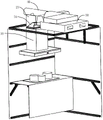
Fig. 1 is a perspective view schematically illustrating a range hood system for an open kitchen according to an embodiment of the present invention.
Fig. 2 is a schematic view illustrating another direction of a range hood system for an open kitchen according to an embodiment of the present invention.
Fig. 3 is a schematic view of a range hood and an air purification device according to an embodiment of the present invention.
Fig. 4 is a schematic view of an air cleaning apparatus according to an embodiment of the present invention.
Fig. 5 is a schematic view of another direction of the air cleaning apparatus of the present invention.
Fig. 6 isbase:Sub>A sectional view taken along linebase:Sub>A-base:Sub>A of fig. 4.
Fig. 7 isbase:Sub>A plan sectional view taken along linebase:Sub>A-base:Sub>A in fig. 4.
Fig. 8 is an exploded view of an air cleaning device according to an embodiment of the present invention.
Fig. 9 is a sectional view taken along line B-B of fig. 4.
Fig. 10 is a schematic view of an air purification unit in the air purification apparatus according to the embodiment of the present invention.
Fig. 11 is a partially enlarged view of fig. 8.
FIG. 12 is a schematic view of a cyclone tube in an air cleaning apparatus according to an embodiment of the present invention.
FIG. 13 is a cross-sectional view of the cyclone tube of FIG. 10.
Fig. 14 is a cross-sectional view of the cyclone tube of fig. 10 in another direction.
Fig. 15 is a sectional view of an air cleaning device according to a second embodiment of the present invention.
Fig. 16 is a plan view of an air cleaning device according to a second embodiment of the present invention.
Fig. 17 is a schematic view of an air cleaning apparatus according to a third embodiment of the present invention.
Detailed Description
The invention is described in further detail below with reference to the accompanying examples.
As shown in fig. 1 and 2, the system for absorbing oil smoke in an open kitchen includes a range hood 10, an air curtain mechanism 70 located near the range hood 10, especially located near a ceiling of the kitchen on one side of the range hood 10 close to a user, and an air purification device 50 located near an air curtain area formed by the air curtain mechanism 70, that is, the air curtain mechanism 70 is located between the air purification device 50 and the range hood 10.
The air curtain mechanism 70 may be independently disposed, or may be integrally formed with the range hood 10, or may be integrally formed with the air purifying device 50. This air curtain mechanism 70 is used for when range hood 10 uses, produces the round air curtain around range hood 10 for the oil smoke can be assembled in air curtain mechanism 70, makes range hood 10 can absorb the oil smoke better. However, since people need to operate the range hood before the range hood, even if the air curtain mechanism 70 is provided, the oil smoke still leaks from the air curtain mechanism 70, and the escaped oil smoke can be completely sucked by the air purification device 50. In addition, an air curtain mechanism 70 may be further provided outside the air purification device 50, so that an air curtain is also formed around the air purification device 50, thereby better removing oil smoke. In addition, the back of the range hood 10 is generally close to a wall, so the air curtain mechanism 70 may be a single piece independently arranged in three directions outside the range hood 10, surround the range hood 10, or form a shape surrounding the range hood 10. The air curtain mechanism 70 may be disposed only at a position facing the user on the front side of the range hood 10, or may surround the range hood 10.
As shown in fig. 3, a three-way valve 30 is disposed on the air outlet 20 of the range hood 10, a first end of the three-way valve 30 is connected to the air outlet 20 and the air outlet housing of the range hood 10, a second end of the three-way valve 30 is communicated with an external flue for discharging the oil smoke generated by the range hood 10 through the flue, a third end of the three-way valve is connected to an air purifying device 50 through a communication pipeline 40, and the three-way valve 30 can switch the oil smoke generated by the range hood 10 to be discharged to the external flue or to be discharged to the air purifying device 50. In order to better remove the oil smoke, other structures such as the oil smoke removing device 60 may be provided in the communication duct 40.
The air purification device 50 includes at least one upward air inlet 11 for connecting with the communication pipeline 40, i.e. connecting with the range hood 10, and includes at least one air inlet 11 communicating with the room and at least one air outlet 12 communicating with the room. The air cleaning apparatus 50 includes a housing 1, and an air cleaning unit 2 provided in the housing 1. The housing 1 is flat and square as shown in fig. 2 and 3, and the housing 1 is provided with an air inlet 11 and an air outlet 12.
As shown in fig. 4 and 5, the air inlet 11 of the housing 1 is located on the upper surface and the lower surface of the housing 1, and the air outlet 12 is located on the circumferential surface of the housing 1. The air inlet of the air purification unit 2 faces the air inlet 11, and the air outlet of the air purification unit 2 may or may not face the air outlet 12 of the housing 1.
As shown in fig. 4 and 5, the casing 1 has two air inlets 11 on the upper surface and the lower surface, and two air outlets 12 are respectively disposed on two opposite peripheral surfaces of the casing 1. And the air outlet of the air cleaning unit 2 is arranged towards the air outlet 12 and the air inlet of the air cleaning unit 2 is arranged towards the air inlet 11. Therefore, two air purification units 2 are provided in the air purification apparatus. In particular, the upper surface and the lower surface of the housing 1 are respectively provided with openings to form the air inlet 11, the air inlet 11 exposes the air inlet of the air purification unit 2, and the air inlet of the air purification unit 2 is located at the position of the air inlet 11. The inner side of the air outlet 12 of the casing 1 is provided with a fan 5, so that the air flow in the casing 1 is guided to the air outlet 12 and discharged, and the air flow is guided to the air outlet 12 and discharged. Namely, the air purification unit 2 and the fan 5 are sequentially arranged in an air flow channel between the air inlet 11 and the air outlet 12 of the shell 1, and other functional modules can be arranged between the air purification unit 2 and the fan 5. The fan 5 is a vortex fan.
As shown in fig. 6, 7 and 8, the air inlets of the two air purification units 2 are respectively arranged downwards and upwards, and the air outlets thereof are two and are respectively arranged towards the air outlets on the two opposite peripheral walls of the housing 1. The external oil smoke gas enters the air purification unit 2 from the air inlet 11 of the housing 1, that is, the air inlet of the air purification unit 2, and is discharged from the air outlet of the air purification unit 2 after oil smoke separation is performed by the air purification unit 2, and the air outlet of the air purification unit 2 is perpendicular to the air inlet thereof, and then is discharged to the outside of the housing 1 from the air outlet 12 of the housing 1. On the wind channel between the air outlet of the air purification unit 2 and the fan 5 of the air outlet 12 of the shell 1, a sterilization module 3 and a refrigeration and heating module 4 can be arranged in sequence, and other functional modules such as a smell removal module and a dehumidification module can be arranged. Therefore, the soot gas passing through the air purifier can be purified and filtered into a clean gas, and further directly discharged from the outlet 12 of the casing 1. The air purification device can be installed on a suspended ceiling of a kitchen, is similar to the position and the structure of an air conditioner or a bathroom ventilator, is small in size and attractive in appearance, can discharge gas indoors instead of outdoors, and is more environment-friendly and free of environmental pollution.
As shown in fig. 9-14, for the structure of the two sets of air purification units 2, each set of air purification units 2 includes at least two cyclone tubes 21 extending in the same direction side by side, the cyclone tubes 21 are hollow and cylindrical, and the two ends of the cyclone tubes 21 are provided with openings to form air outlets 213, and the middle part of the side wall 211 of the cyclone tube 21 is provided with an opening extending along the axial direction of the cyclone tube 21 to form an air inlet 212. The periphery of the air inlet 212 is formed with a circle of wind scoops 214 extending outward, the wind scoops 214 include two opposite first guide surfaces 2141 and second guide surfaces 2142 extending in the axial direction of the cyclone tube 1, wherein the first guide surfaces 2141 extend perpendicularly from the air inlet 212 outward along the tangent line of the sidewall 211 of the cyclone tube 21, and the second guide surfaces 2142 extend from the air inlet 212 outward gradually away from the first guide surfaces 2141. Therefore, under the action of the fan, the oil smoke entering the cyclone tube 21 from the air inlet 212 can rotate and accelerate in the cyclone tube 21, and then the oil smoke gas collides with the sidewall of the cyclone tube 21, because there is friction between oil droplets and the sidewall of the cyclone tube 21, the oil droplet molecules will remain in the sidewall of the cyclone tube 21, and the gas separated from the oil droplet molecules gradually moves towards both ends, and is discharged from the air outlet 213.
In order to further separate oil droplets from gas, a wire 22 is provided inside the cyclone tube 21 and extends along the axial direction thereof, preferably, the wire 22 extends along the center of the cyclone tube 21, and the air cleaning unit further includes a high voltage electrostatic generator (not shown), one of the positive and negative electrodes of which is connected to the sidewall 211 of the cyclone tube 21, and the other of the positive and negative electrodes of which is connected to the wire 22. When the high voltage electrostatic generator is operated, a cylindrical electric field is formed inside the cyclone tube 21, free electrons in the air move to two poles under the action of the cylindrical electric field, and after the voltage of the electric field rises to a certain value, most oil smoke molecules are combined with negative electrons to form negative ions when the air containing the oil smoke molecules spirally passes through the cyclone tube 21, and the negative ions are deposited on one pole of the side wall 211 of the cyclone tube 21 under the action of the electric field. The separation rate of oil smoke gas is improved more, and the gas passing through the air purification unit is cleaned better.
Therefore, the structure of the cyclone tube can enable the gas to rotate, has the capability of filtering large particles, effectively increases the probability of capturing and decomposing substances, and makes up the function that static plasma cannot complete; and the charged conducting wire is added in the middle of the cyclone tube, so that the defect that the cyclone tube structure is insufficient in capturing small particles is overcome, oil drop molecules can be removed, other space and volume are not occupied, a structure is not required to be additionally arranged, and an electric field can be realized by utilizing the structure of the cyclone tube. Compared with the existing filter screen filtering structure, the cyclone tube has large inner diameter and is not easy to block, the cleaning period is greatly prolonged, the permanent use is not required, and the use cost is greatly reduced.
As shown in fig. 9 and 10, the air purification apparatus includes two sets of air purification units arranged up and down, and each set of air purification unit includes a plurality of cyclone tubes 21 arranged side by side, the extension directions of the cyclone tubes 21 in the two sets of air purification units are the same, the air inlets 212 of each cyclone tube 21 in each set of air purification unit are oriented in the same direction, and the air inlets of the cyclone tubes 21 in the two sets of air purification units are oriented in opposite directions, that is, the air inlets 212 of the cyclone tubes 21 in the lower set of air purification unit are arranged downward, the air inlets 212 of the cyclone tubes 21 in the upper set of air purification unit are arranged upward, and the air inlets 212 of the cyclone tubes 21 in each set of air purification unit 2 are respectively opposite to the air inlet 11 on the upper surface of the housing 1 and the air inlet 11 on the lower surface of the housing 1. The air outlets 213 of at least two cyclone tubes 21 in the air purification unit 2 are air outlets of the air purification unit 2, in this embodiment, the two air purification units 2 include air outlets on two sides.
The air cleaning unit further comprises a fixing frame 23 for fixing at least two cyclone tubes, a support 231 with a flat plate shape of the fixing frame 23, and an opening 232 which is positioned on the support 231 and is matched with the shape of the wind scooper 214 of the cyclone tube 21, wherein the periphery of the opening 232 is provided with a fixing edge 233 which extends towards the wind scooper 214 and is respectively positioned on the inner side of the wind scooper 214. The fixing frame 23 can guide and position the cyclone tube 21 to form a whole. The fixing frames 23 of the two air purification units can be integrally formed or can be separately formed and fixed to each other. The cyclone pipes in each group of air purification units can be integrally formed with the wind scooper, so that the structure is simple, the processing is convenient, the integrity of the oil fume filtering part is improved, and the oil fume is prevented from escaping. The holder 23 further includes a side plate 235 perpendicular to the plate-shaped holder 231, the side plate 235 being used to hold the end of the cyclone tube 21, and the wires 22 are connected to the high voltage electrostatic generator through the side plate 235. In the two sets of air purification units shown in fig. 6 and 7, the cyclone tubes 21 of each set of air purification units share the side plates 235 at two sides, i.e., the side plates 235 in each set of air purification units are connected or integrally formed. The outlet 12 of the housing 1 may be provided with a guide vane for adjusting the direction of the wind, so that the direction of the blown gas can be adjusted.
As shown in fig. 15 and 16, which are schematic views of a second embodiment of an air purification apparatus 50 according to the present invention, a housing 1 of the air purification apparatus in this embodiment is a flat circular shape, an air inlet 11 is provided on a peripheral surface of the housing 1, an air outlet 12 is provided on a lower surface of the housing 1, and an air inlet 11 is also provided on an upper surface of the housing 1, for connecting a range hood 10 in a kitchen.
An air purification unit 2, other functional modules and a fan 5 are sequentially arranged in an air flow channel from the air inlet 11 to the air outlet 12, the air purification unit 2 can be of the structure of the air purification unit 2 as described in the embodiment, and can also comprise a coarse filtering unit 100 and a fine filtering unit 200, and the other functional modules comprise a sterilization module 3, and at least one of a refrigeration and heating module 4, a smell removal module and a humidification module. The coarse filtering unit 100 may be the structure of the air purifying unit 2, or may be other air purifying structures, and is used for filtering oil smoke with larger particles; the fine filtering unit 200 may be a filter screen structure as shown in fig. 11, or may be another air purifying unit for filtering oil smoke with small particles. That is, the air cleaning unit 2 includes the above-described structure.
The coarse filtering unit 100 is arranged in a circle at the inner side of the peripheral surface of the housing 1, that is, a circle of cyclone tubes 21 is arranged in a circle at the periphery of the housing 1, air inlets 212 of the cyclone tubes 21 face the outer side of the peripheral surface of the housing 1, the fine filtering unit 200 is positioned above the middle of the housing 1, an air inlet 11 at the upper surface of the housing 1 is arranged above the fine filtering unit 200, a sterilization module 3, a refrigeration and heating module 4 and a fan 5 are arranged below the fine filtering unit 200, that is, the middle position of the coarse filtering unit 100, and the sterilization module 3 and the refrigeration and heating module 4 are other functional modules. The side surfaces of the other functional modules are spaced from the coarse filter unit 100, that is, the airflow enters the housing 1 from the air inlet 11 on the peripheral surface of the housing 1, passes through the coarse filter unit 100, then goes upward, enters the fine filter unit 200 and the other functional modules from the upper side, then passes through the fine filter unit 200 and the other functional modules in sequence, and is discharged from the air outlet 12 in the middle of the lower side.
As shown in fig. 17, which is a schematic view of a third embodiment of the air purifying device 50 of the present invention, the housing 1 in this embodiment is cylindrical, and the air inlets 11 are located on the upper surface and the lower surface of the housing 1, and the air outlets 12 are located on the peripheral surface of the housing 1. The middle position of the shell 1 is provided with a fan 5, the air outlet of the fan 5 is connected to the air outlets 12 on the peripheral surface of the shell 1, the air inlet of the fan 5 is respectively communicated with the air inlets 11 on the upper surface and the lower surface of the shell 1 in an upward and downward mode, and a coarse filtering unit 100, a fine filtering unit 200 and other functional modules are further arranged between the fan 5 and the air inlets 11.
That is, the air purification unit 2, the air purification unit 300 and the blower 5 are sequentially arranged on the air flow channel between the air inlet 11 and the air outlet 12, the air purification unit 2 includes a coarse filtration unit 100 and a fine filtration unit 200, or only the coarse filtration unit 100 or the fine filtration unit 200 may be provided, and the other functional modules may include at least one of the sterilization module 3, the refrigeration and heating module 4, the odor removal module and the humidification module. Other functional modules may not be provided.
Therefore, the oil smoke generated from the range hood 10 can enter from the air inlet 11 on the upper surface of the air purification device 50 through the three-way valve 30 and the communication pipeline 40, and is filtered and purified through the upper one of the two sets of air purification units 2 which are arranged in the housing 1 and intake up and down, and then is discharged from the air outlets 12 on the peripheral side walls of the housing 1, and the air purification unit 2 which is arranged in the housing 1 with the other set of air inlets downward can suck other oil smoke gas in the kitchen through the air inlet 11 on the lower surface of the housing 1 and also is discharged from the air outlets 12 on the peripheral side walls of the housing 1. And when the range hood 10 is not used, air can be sucked from the air purification unit 2 below to perform the functions of oil smoke purification or air purification. Of course, those skilled in the art may also think that the air inlet is disposed on the upper surface of the housing 1, the air inlets are also disposed on the peripheral side walls of the housing 1, and the air outlet is disposed on the lower surface of the housing 1.
The range hood 10 and the smoke exhaust duct 20 can form a smoke exhaust system, the range hood 10 and the air purification device 50 can form an internal circulation purification system, and the air curtain mechanism 70 can form an airflow blocking system, for example, an airflow curtain blowing downward and outward can be formed around the range hood to block the airflow. In addition, the air conditioner is also provided with a heat exchange system which can be independently arranged, such as an air conditioner and the like, or a refrigerating and heating module is arranged in the indoor air purification device, and in addition, a fresh air compensation system can be arranged, wherein the fresh air compensation system can be a corresponding module arranged in the indoor air purification device or can be independently arranged. And the fresh air compensation system also comprises an oxygen increasing module which is used for adjusting the oxygen content of the indoor space. The fresh air compensation system can be formed in the air curtain mechanism 70, or can be formed independently, i.e. ventilation ports are arranged at the top of each position in the kitchen.
In addition, the air purification device, namely the internal circulation purification system, can further comprise a smell removal module, a sterilization module and the like, and is used for performing smell removal and sterilization functions on indoor air.
This an oil absorption cigarette system for open kitchen can also include self-cleaning system, and this self-cleaning system can utilize steam or other principles etc. to clean air purification device, refrigeration heating module etc. has included the air purification unit in this air purification device moreover, can accomplish thorough oil smoke separation, and then also can realize not needing to clean for a long time.
The oil smoke suction system for the open kitchen needs to include various sensors, including a smoke sensor, a humidity sensor, a temperature sensor and the like, which can be respectively and independently arranged or installed in each device, and the sensors are connected to a signal processing and transmitting-receiving system. The signal processing and transmitting-receiving system is used for controlling the switches of the systems. And the information processing and receiving and transmitting system is also connected with a gas system comprising a cooker and used for controlling the on-off of the cooker.
When the signal control and receiving and transmitting system receives a signal of starting up the cooker, the smoke discharging system can be started to actively discharge a large amount of smoke out of the room, and meanwhile, the airflow blocking system is started to close the cooking area in the air curtain, so that the smoke in the area can not overflow. When the internal circulation purification system obtains the signal that the oil smoke exists at the position, the internal circulation purification system is immediately started to suck and purify the smoke and then discharge the smoke. And when the ambient temperature reaches a set interval, starting the heat exchange system to work.
When gas leakage is detected, the processor instructs to close the gas valve, and simultaneously opens the smoke discharge system and the fresh air compensation system, so that the indoor gas concentration is minimized as soon as possible, and information is sent to a designated user to prompt the designated user to return to the processing in time.
When the system is idle, the self-cleaning system performs self-cleaning according to the environmental condition in the equipment, so that secondary pollution can be avoided.
When the indoor oxygen content is detected to be lower than the set value, the oxygen increasing system starts to work to provide high-concentration oxygen to the indoor.
This an oil absorption cigarette system for open kitchen has range hood, air curtain mechanism and air purification device, can clear away the oil smoke well to indoor discharge clean air can carry out the purification regulation of indoor air moreover, not only purified indoor air, also can guarantee the fresh of outdoor air, prevent atmospheric pollution.
Although preferred embodiments of the present invention have been described in detail hereinabove, it should be clearly understood that modifications and variations of the present invention are possible to those skilled in the art. Any modification, equivalent replacement, or improvement made within the spirit and principle of the present invention should be included in the protection scope of the present invention.
Claims (8)
1. The utility model provides a range hood system for open kitchen, includes range hood (10), is located range hood (10) near install air curtain mechanism (70) of neighbouring kitchen ceiling position, its characterized in that: the air curtain device further comprises an air purification device (50) which is positioned near an air curtain area formed by the air curtain mechanism (70), wherein the air purification device (50) comprises at least one air inlet (11) communicated with the indoor space, and the air purification device (50) further comprises at least one air outlet (12) communicated with the indoor space;
the air purification device (50) comprises a shell (1) and an air purification unit (2) positioned in the shell (1), wherein the shell (1) is provided with an air inlet (11) and an air outlet (12), the air inlet (11) is communicated with an air inlet of the air purification unit (2), the air outlet of the air purification unit (2) is perpendicular to the air inlet of the air purification unit (2), a fan (5) is arranged in the shell (1), and the air purification unit (2) comprises a coarse filtration unit (100) and/or a fine filtration unit (200);
the air purification device comprises two groups of air purification units (2) which are arranged up and down, wherein two air outlets of each group of air purification unit (2) respectively face two opposite peripheral surfaces of the shell (1), air outlets (12) are arranged on the two opposite peripheral surfaces of the shell (1), each group of air purification unit (2) comprises at least two parallel cyclone tubes (21) extending in the same direction, the cyclone tubes (21) are hollow cylinders, air inlets (212) extending along the axial direction of the cyclone tubes (21) are arranged in the middle parts of the side walls (211) of the cyclone tubes (21), air outlets (213) are formed at two ends of the cyclone tubes (21), and a circle of air guide cover (214) extending outwards is arranged on the periphery of each air inlet (212); the direction of an air inlet (212) of each cyclone tube (21) in each group of air purification units (2) is the same, the directions of air inlets of the cyclone tubes (21) in the two groups of air purification units (2) are opposite, the air inlets (212) of the cyclone tubes (21) in each group of air purification units (2) respectively face an air inlet (11) on the upper surface of the shell (1) and an air inlet (11) on the lower surface of the shell (1), air outlets (213) of at least two cyclone tubes (21) in the air purification units (2) are air outlets of the air purification units (2), the cyclone tubes (21) form the coarse filtration unit (100), and a fan (5) is arranged on the inner side of an air outlet (12) of the shell (1); or
The air purification unit (2) comprises a circle of cyclone tubes (21) arranged along the periphery of the shell (1), the cyclone tubes (21) are hollow cylinders, an air inlet (212) axially extending along the cyclone tubes (21) is formed in the middle of a side wall (211) of each cyclone tube (21), an air outlet (213) is formed in at least one end of each cyclone tube (21), the air inlet (212) of each cyclone tube (21) faces the outer side of the periphery of the shell (1), a circle of wind scooper (214) extending outwards is arranged on the periphery of each air inlet (212) and is opposite to the air inlet of the shell (1), the cyclone tubes (21) form the coarse filtering unit (100), the fine filtering unit (200) is positioned above the middle of the shell (1), a fan (5) is arranged above the fine filtering unit (200), and the middle position of the coarse filtering unit (100) is below the fine filtering unit (200), and the other fan (5) is positioned below the fine filtering unit (200).
2. The system of claim 1, wherein: the air purification device (50) further comprises at least one air inlet (11) communicated with the range hood (10).
3. The system of claim 2, wherein: the air outlet (20) of the range hood (10) is communicated to a first end of a three-way valve (30), a second end of the three-way valve (30) is connected to an external flue, and a third end of the three-way valve is connected to a communication pipeline (40) and is connected to an air purification device (50) through the communication pipeline (40).
4. The range hood system for an open kitchen of claim 3, wherein: and a lampblack removing device (60) is also arranged in the communicating pipeline (40).
5. The system of claim 4, wherein: the air purification unit is characterized in that other functional modules are arranged on an air channel between an air outlet of the air purification unit (2) and the fan (5) of the shell (1), and the other functional modules comprise at least one of a sterilization module (3), a refrigeration and heating module (4), a smell removal module and a humidification module.
6. The range hood system for an open kitchen of claim 1, wherein: still include flue gas sensor, humidity transducer, temperature sensor to and with the signal processing and the receiving and dispatching system that above-mentioned flue gas sensor, humidity transducer, temperature sensor all are connected, signal processing and receiving and dispatching system are connected to air purification device (50).
7. The range hood system for an open kitchen of claim 5, wherein: the sterilizing module (3), the refrigerating and heating module (4), the odor removing module and the humidifying module are arranged from the air outlet to the air outlet of the air purifying unit (2) and are arranged on the shell (1) in sequence.
8. The system of claim 1, wherein: the middle position of the below of the fine filtering unit (200) is provided with other functional modules, the side surfaces of the other functional modules are separated from the coarse filtering unit (100), gas discharged from the coarse filtering unit (100) upwards enters the fine filtering unit (200) and then enters the other functional modules after passing through the fine filtering unit (200).
Priority Applications (1)
| Application Number | Priority Date | Filing Date | Title |
|---|---|---|---|
| CN201610365318.9A CN107435961B (en) | 2016-05-27 | 2016-05-27 | Oil fume suction system for open kitchen |
Applications Claiming Priority (1)
| Application Number | Priority Date | Filing Date | Title |
|---|---|---|---|
| CN201610365318.9A CN107435961B (en) | 2016-05-27 | 2016-05-27 | Oil fume suction system for open kitchen |
Publications (2)
| Publication Number | Publication Date |
|---|---|
| CN107435961A CN107435961A (en) | 2017-12-05 |
| CN107435961B true CN107435961B (en) | 2022-10-25 |
Family
ID=60453726
Family Applications (1)
| Application Number | Title | Priority Date | Filing Date |
|---|---|---|---|
| CN201610365318.9A Active CN107435961B (en) | 2016-05-27 | 2016-05-27 | Oil fume suction system for open kitchen |
Country Status (1)
| Country | Link |
|---|---|
| CN (1) | CN107435961B (en) |
Families Citing this family (5)
| Publication number | Priority date | Publication date | Assignee | Title |
|---|---|---|---|---|
| CN110657519A (en) * | 2018-06-29 | 2020-01-07 | 宁波方太厨具有限公司 | Kitchen air conditioning system |
| CN110345537A (en) * | 2019-07-31 | 2019-10-18 | 宁波东大空调设备有限公司 | Kitchen air purifying Contiuum type unit |
| CN110594818B (en) * | 2019-09-16 | 2021-07-23 | 宁波方太厨具有限公司 | Range hood and control method thereof |
| CN111720871B (en) * | 2020-07-04 | 2023-03-28 | 中山市喜玛拉雅电器有限公司 | Lampblack absorber is recycled to oil smoke |
| CN114263948A (en) * | 2020-09-25 | 2022-04-01 | 佛山市顺德区美的洗涤电器制造有限公司 | Range hood, range hood control method and device and computer storage medium |
-
2016
- 2016-05-27 CN CN201610365318.9A patent/CN107435961B/en active Active
Also Published As
| Publication number | Publication date |
|---|---|
| CN107435961A (en) | 2017-12-05 |
Similar Documents
| Publication | Publication Date | Title |
|---|---|---|
| CN107435961B (en) | Oil fume suction system for open kitchen | |
| CN205717436U (en) | A kind of Integral type kitchen structure | |
| CN107202396B (en) | Dual cycle formula new trend system and new fan | |
| CN107435963B (en) | Integral kitchen structure | |
| CN107435964B (en) | Air curtain system for preventing oil smoke from escaping | |
| CN107435962B (en) | Control system and control method for open kitchen air environment | |
| CN102261687A (en) | Air purification unit device of range hood | |
| CN105444301A (en) | Purification air conditioner | |
| CN205897261U (en) | Kitchen air clean system | |
| CN108240692B (en) | Kitchen fresh air system | |
| CN205783189U (en) | A kind of control system of open air in kitchen environment | |
| CN107435959B (en) | Indoor air purification system | |
| CN113251455B (en) | Civil integrated oil fume purification and collection all-in-one machine and purification method thereof | |
| CN108061321B (en) | Kitchen refrigerating range hood | |
| CN206001608U (en) | A kind of kitchen air purifying device | |
| CN209295222U (en) | A kind of kitchen indoor air cleaning system | |
| CN101793418A (en) | Oil fume pump exhaust purifier | |
| CN107435991B (en) | Room air purification system | |
| CN205717621U (en) | Indoor air cleaning system | |
| CN215863620U (en) | Double-ring type efficient oil fume purifier | |
| CN211476214U (en) | Ceiling type fresh air machine with oil fume purification function | |
| CN107435960B (en) | Kitchen air purification system | |
| KR102210161B1 (en) | Hybrid air purification system | |
| CN210631831U (en) | Side-suction type smokeless purifier | |
| CN109915970A (en) | A kind of integrated fresh air purifying unit of kitchen furred ceiling |
Legal Events
| Date | Code | Title | Description |
|---|---|---|---|
| PB01 | Publication | ||
| PB01 | Publication | ||
| SE01 | Entry into force of request for substantive examination | ||
| SE01 | Entry into force of request for substantive examination | ||
| GR01 | Patent grant | ||
| GR01 | Patent grant |