CN107430421B - Powered device in power over ethernet network system and method thereof - Google Patents
Powered device in power over ethernet network system and method thereof Download PDFInfo
- Publication number
- CN107430421B CN107430421B CN201680014186.3A CN201680014186A CN107430421B CN 107430421 B CN107430421 B CN 107430421B CN 201680014186 A CN201680014186 A CN 201680014186A CN 107430421 B CN107430421 B CN 107430421B
- Authority
- CN
- China
- Prior art keywords
- power
- powered device
- pse
- type information
- request
- Prior art date
- Legal status (The legal status is an assumption and is not a legal conclusion. Google has not performed a legal analysis and makes no representation as to the accuracy of the status listed.)
- Active
Links
Images

Classifications
-
- G—PHYSICS
- G06—COMPUTING; CALCULATING OR COUNTING
- G06F—ELECTRIC DIGITAL DATA PROCESSING
- G06F1/00—Details not covered by groups G06F3/00 - G06F13/00 and G06F21/00
- G06F1/26—Power supply means, e.g. regulation thereof
- G06F1/266—Arrangements to supply power to external peripherals either directly from the computer or under computer control, e.g. supply of power through the communication port, computer controlled power-strips
-
- H—ELECTRICITY
- H04—ELECTRIC COMMUNICATION TECHNIQUE
- H04L—TRANSMISSION OF DIGITAL INFORMATION, e.g. TELEGRAPHIC COMMUNICATION
- H04L12/00—Data switching networks
- H04L12/02—Details
- H04L12/10—Current supply arrangements
-
- H—ELECTRICITY
- H04—ELECTRIC COMMUNICATION TECHNIQUE
- H04L—TRANSMISSION OF DIGITAL INFORMATION, e.g. TELEGRAPHIC COMMUNICATION
- H04L12/00—Data switching networks
- H04L12/28—Data switching networks characterised by path configuration, e.g. LAN [Local Area Networks] or WAN [Wide Area Networks]
- H04L12/40—Bus networks
- H04L12/40006—Architecture of a communication node
- H04L12/40045—Details regarding the feeding of energy to the node from the bus
-
- H—ELECTRICITY
- H04—ELECTRIC COMMUNICATION TECHNIQUE
- H04L—TRANSMISSION OF DIGITAL INFORMATION, e.g. TELEGRAPHIC COMMUNICATION
- H04L69/00—Network arrangements, protocols or services independent of the application payload and not provided for in the other groups of this subclass
- H04L69/30—Definitions, standards or architectural aspects of layered protocol stacks
- H04L69/32—Architecture of open systems interconnection [OSI] 7-layer type protocol stacks, e.g. the interfaces between the data link level and the physical level
- H04L69/322—Intralayer communication protocols among peer entities or protocol data unit [PDU] definitions
- H04L69/324—Intralayer communication protocols among peer entities or protocol data unit [PDU] definitions in the data link layer [OSI layer 2], e.g. HDLC
-
- Y—GENERAL TAGGING OF NEW TECHNOLOGICAL DEVELOPMENTS; GENERAL TAGGING OF CROSS-SECTIONAL TECHNOLOGIES SPANNING OVER SEVERAL SECTIONS OF THE IPC; TECHNICAL SUBJECTS COVERED BY FORMER USPC CROSS-REFERENCE ART COLLECTIONS [XRACs] AND DIGESTS
- Y02—TECHNOLOGIES OR APPLICATIONS FOR MITIGATION OR ADAPTATION AGAINST CLIMATE CHANGE
- Y02D—CLIMATE CHANGE MITIGATION TECHNOLOGIES IN INFORMATION AND COMMUNICATION TECHNOLOGIES [ICT], I.E. INFORMATION AND COMMUNICATION TECHNOLOGIES AIMING AT THE REDUCTION OF THEIR OWN ENERGY USE
- Y02D30/00—Reducing energy consumption in communication networks
Landscapes
- Engineering & Computer Science (AREA)
- General Engineering & Computer Science (AREA)
- Theoretical Computer Science (AREA)
- Computer Networks & Wireless Communication (AREA)
- Signal Processing (AREA)
- Computer Hardware Design (AREA)
- Physics & Mathematics (AREA)
- General Physics & Mathematics (AREA)
- Small-Scale Networks (AREA)
- Power Sources (AREA)
Abstract
The present invention relates to a Powered Device (PD) in a power over ethernet (PoE) system. The present invention proposes that a PD selectively transmit a power request to a Power Sourcing Equipment (PSE) based on the PSE's support for autoclass. A PSE supporting autoclass will determine the maximum power that needs to be allocated to a PD based on measuring the power used by the autoclass-capable PD during classification. If the PSE does not support autoclass, it will instead allocate a default maximum power (based on classification) to the PD. When the PD is operational, it determines whether autoclassification is supported by the PSE (230). If autoclass is supported, no power request should be sent (250), otherwise the PSE will allocate power based on the request rather than based on a more accurate measurement.
Description
Technical Field
The present invention relates to a powered device (arranged for use in a power over ethernet network system), a method of operating such a powered device and a computer program for operating such a powered device.
Background
In the latest standard, IEEE Standard 802.3af-2003, section 3: carrier Sense Multiple Access with colloid Detection (CSMA/CD) Access Method and Physical layer Specifications, amino Data Terminal Equipment (DTE) Power via Media Dependent Interface (MDI); power over Ethernet (PoE) is described in IEEE Computer Society. With PoE, power is supplied to separate data equipment and peripherals (such as routers, switches, printer daemons, etc.) through the same wired or network connections that have been used to connect them to the ethernet (network). There are plans to utilize the same standard for all kinds of low power loads, such as for example lighting devices (sensors, switches, light sources, etc.) or entertainment appliances (such as active speakers, internet radio, DVD players, set-top boxes and even television sets). Standardization in IEEE Standard 802.3 is ongoing to support power levels of, for example, up to 100W per Cat5/6 connection.
As PoE supply systems for power distribution within buildings become the focus of the industry, some specific use aspects of these networks need to be addressed in order for direct current supply networks (so-called "dc grids") to be widely adopted. Historically, when the PoE standard was introduced for powering separate networking devices such as routers, switches, printer daemons, etc., it was an alternative to small power plug-type power supplies, since the originally intended load was mostly already equipped with communication and processing means.
As indicated above, an example of a powered device may be a light source, but may also be a sensor or an actuator. Typically, two links between Power Sourcing Equipment (PSE) and Powered Device (PD) are foreseen. The power delivery link is established after detection and classification. Subsequently, a data link is established for the conventional ethernet data.
One aspect of interest in the standardization activities of PoE relates to power distribution. The 802.3af standard allows the PSE to distinguish between several power classes, and the 802.3at standard adds support for additional power classes and continuous negotiation between the PSE and the PD. The ability of the PSE to query the PD to determine the power requirements of the PD is referred to as classification. The interrogation and power classification functions are intended to establish mutual identification and are intended for use with advanced power features such as power management. There are two forms of fractionation: physical layer hierarchy and data link layer hierarchy. Physical layer classification occurs before the PSE supplies power to the PD when the PSE adheres (assert) to the voltage on the physical interface and the PD responds with a current that represents a limited number of power classifications. With data link layer classification, the PSE and the PD communicate using a data link layer protocol after the data link is established. Data link layer classification has finer power resolution and the ability of the PSE and PD to participate in dynamic power allocation, where the power allocated to the PD may change one or more times during PD operation.
The improved classification feature in the 802.3at standard compared to the 802.3af standard may be used to prevent the PSE from allocating too much power to the PD, i.e., the power limit that the PD will never use, with the result that the excess is reserved without due reason. However, more advanced power distribution methods are needed to further optimize power distribution.
A new standard is being developed for PoE-the 802.3bt standard, which will introduce a new hierarchical mechanism: and (6) automatically grading. Autoclass is a classification mechanism that allows a PD to communicate its effective maximum power consumption to a PSE. This occurs in such a way that: such that the PSE will be able to set the power budget to an effective maximum PD power that includes effective channel losses (e.g., losses realized over an ethernet connection between the PSE and the PD). This will allow for a more efficient use of the Power Supply Unit (PSU) of the PSE, since only the power used efficiently needs to be budgeted. Autoclass is performed as part of the classification process, where the PSE determines what class to assign to a connected PD. In the autoclass mode, the PD consumes maximum power for a short period during classification, and the PSE measures the consumed power. The PSE will then allocate power to the PD based on the measurement.
The Lennart Yeebodt et al statement "Autoclass II vl 60" in the context of "IEEE P802.3bt 4-Pair Power over Ethernet (4PPoE) -January 2015 Interim Meeting" of Atlanta, georgia, USA, on days 1-16 of 2015 discloses an introduction to part of the above described automated ranking principle.
Statement "IEEE P802.3bt Mutual Identification" by David Abramson in the context of "IEEE P802.3bt 4-Pair Power over Ethernet (4PPoE) -September 2014 Interim Meeting" at Canada, Ontario, 9, 10-12, 2014 discloses a Mutual Identification scheme for PDs and PSEs to learn about the capabilities/requirements of the other party.
Disclosure of Invention
The Link Layer Discovery Protocol (LLDP) can also be used to (re-) trigger or cancel automatic classification after being triggered at the physical layer (i.e. as part of the classification process). Triggering automatic classification via LLDP is a solution for PDs that cannot meet the start-up timing requirements of physical layer automatic classification (e.g., PDs that cannot consume maximum power for a short time after being powered up). For example, automatic classification may provide more accurate power distribution than data link layer classification because it takes into account actual cable losses. However, when PSE and PD feature autoclass also supports the PD sending data link layer classification, the data link layer classification will overrule the power allocation determined based on the autoclass feature. This may then result in a less accurate power distribution.
It is an object of the present invention to provide an improved powered device, an improved method of operating a powered device and a computer program for operating a powered device.
In one aspect of the invention, there is provided a powered device for receiving power from power sourcing equipment via a communication link (e.g. an ethernet cable or other cable allowing power distribution and data communication), the powered device comprising: a communication unit arranged to transmit a power request over a communication link; and a controller unit arranged for controlling a powered device in a maximum power mode during a classification phase of the powered device. The powered device (e.g. the controller unit) is arranged for determining type information related to the power sourcing equipment, and the communication unit is further arranged for selectively transmitting the power request based on the determined type information (e.g. the controller unit controls the communication unit to transmit the power request based on the determined type information). This is beneficial because it allows, for example, the PD to send a power request only when this results in better power allocation (e.g., more efficient power allocation on the PSE side), or only when the power allocated to the PD needs to be determined by the PD (e.g., if the PD has determined that insufficient power is allocated using autoclass, e.g., based on the maximum power not available after the classification phase). Whether the PSE supports autoclass may be determined based on any of the following: information provided by the PSE (e.g., via LLDP) based on power characteristics of power provided by the PSE to the PD (e.g., based on a classification procedure), based on settings stored as part of an installation or commissioning procedure, based on a rule-based determination (e.g., sending a power request if the PSE's manufacturer name equals "brand name"), etc.
In various embodiments of the powered device according to the invention, the powered device is arranged for determining the type information based on power received from the power sourcing equipment via the communication link and/or based on received type indicator data. Such type indicator data may be received, for example, over a wireless communication link, may be received or retrieved from local memory, and so forth. In an advantageous embodiment, the type indicator data is received via a communication link, for example from a device in a network of which the PD is a part (e.g. from power supply equipment). The type indicator data may comprise a PSE manufacturer code, a network or network device name, etc., and the data may be received in one or more formats. In a particularly advantageous embodiment, the type indicator data is received as a link layer discovery protocol message.
In a further embodiment of the powered device according to the invention, the determined type information specifies a support of the power sourcing equipment for automatic classification. When the PD may determine whether the PSE supports autoclass, the communication unit may be arranged for transmitting the power request when the determined type information indicates support of autoclass by the power supply equipment. When the support for autoclass can be determined explicitly, e.g. because the PSE sends an LLDP message specifying its support for autoclass, it can be easily determined whether to send the power request (e.g. as an LLDP message). When the support of autoclass by the PSE is uncertain (e.g., if no LLDP message is received from the PSE), for example, if the type indicator data indicates that the PSE may or may not support autoclass, the determination of whether to send a power request may be based on more complex logic. For example, if the PD requires 8W of power for optimal operation, it is preferably identified by the PSE as a class 3 PD and assigned to the PD using an autoclass feature that is less than the maximum amount of power for the class 3 PD. If the PSE supports only a PD of at most class 2 and the PD is capable of acting as a class 2 PD (e.g., by limiting its functionality, such as by limiting light output in the case of a PD that is a luminaire), it may be undesirable to limit the power allocation to any value below the maximum power allocated to the class 2 PD.
In a further aspect of the invention, there is provided a method of operating a powered device for receiving power from a power sourcing equipment via a communication link (e.g. an ethernet cable or other cable allowing power distribution and data communication), the method comprising: the method includes providing classification information to a communication link, controlling a powered device in a maximum power mode during a predetermined period of time, determining type information related to power sourcing equipment, and selectively transmitting a power request based on the determined type information. In the following example, the PD is coupled to the PSE via an ethernet cable, and the PSE identifies the PD based on the presence of a 25k Ω resistor (i.e., detecting a signature resistance between 19 and 26,5k Ω). The PD will then apply the method by providing classification information to the communication link (e.g., by providing a power consumption signature, by placing more than one specific pair or pairs of resistors in the cable). Some current surge may occur as a PSE, knowing the class in which the PD is located, provides power to the PD over the communication link. The PD enters a maximum power mode, for example, after a surge, and then the PSE supporting the autoclass feature will measure the power used by the PD. The maximum power mode may include the PD fully turning on a load that it is a part of, or that it powers (e.g., if the load is a luminaire, the light sources may be dimmed to achieve maximum light output and maximum power usage), or alternatively it may include the PD turning on a dedicated circuit (e.g., the maximum power usage may be simulated, e.g., the amount of power dissipated through a resistor is equal to the maximum amount of power that the load will require). After a predetermined amount of time (e.g., as specified by the PoE standard), the PD will go from maximum power mode to, for example, normal (or operational) power mode. In various scenarios, the PSE may then send information to the PD, the PD may retrieve the information (e.g., from memory), the PD may request the information (e.g., from the PSE), etc., to determine type information related to the power supply equipment. The determined type information is used to determine whether to send a power request (e.g., as an LLDP message) to the PSE.
In yet another aspect of the present invention, a computer program product for operating a powered device for receiving power via a communication link is provided, the computer program comprising program code means for causing the powered device to carry out the steps of the method of operating the powered device, when the computer program is run on a computer controlling the powered device. Such a computer program product may be stored in a memory of the PD so that the PD can execute it. As another example, it may be downloaded by the PD as part of, for example, a firmware upgrade.
Herein, the term "power sourcing equipment" (PSE) may for example refer to a DTE or midspan device that provides power to a single link section (i.e. part of the link from the PSE to the PD). The term "powered device" (PD) generally refers to a device that draws power from a PSE or requests power. In one simple example, the communication link as used herein may be an ethernet cable coupling the PSE and PD to each other.
It shall be understood that the powered device, the method of operating a powered device and the computer program for operating a powered device have similar and/or identical preferred embodiments as defined in the dependent claims.
It shall be understood that preferred embodiments of the invention may also be any combination of the dependent claims or the above embodiments with the respective independent claims.
These and other aspects of the invention are apparent from and will be elucidated with reference to the embodiments described hereinafter.
Drawings
In the following drawings:
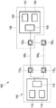
FIG. 1 shows a typical layout of a PoE system, an
Fig. 2 shows schematically and exemplarily an embodiment of the method according to the invention.
Detailed Description
Fig. 1 shows a typical layout of a PoE system 100, the PoE system 100 comprising Power Sourcing Equipment (PSE) 110 and a PoE load 120, the PoE load 120 comprising a Powered Device (PD) 121. The PoE connection can be made via a plurality of output jacks in the PSE 110Or port 1121, …, 112nWith the input jack or port 122 of the PD 1211, ..., 122nSo-called patch cable 150 in between1, …, 150nTo be implemented. In a PoE system, typically both PSE power supply unit 113 and PD power supply unit 123 (for receiving power from the PSE and supplying it to a load) as well as PSE data processing unit 114 and PD data processing unit 124 share the same PoE connection 1501, …, 150n. In a multi-load system, each load is connected to a first port 112 comprising a PSE 1101To the nth port 112nWithin a single one of the plurality of output ports, and the PSE control unit 115 is configured to control the correct power supply. Thus, each load, such as the PD 121, respectively indicates suitability for receiving power over an ethernet connection, and respectively negotiates the availability of the required power with the PSE 110. This requires a PD control unit 125 in each PD 121. On the PSE 110 side, the PSE control unit 115 supervises the negotiation on all ports.
According to IEEE standard 802.3af, which does not support the autoclass feature, a PD may be classified by the PSE based on classification information provided by the PD. By classifying the PD, the PSE is intended to be informed of the maximum power required by the PD during operation. Level 0 is the default value for PD. Grades 1 to 3 may be used for alternative power management schemes at the PSE. Classification of PDs is based on power. The classification of a PD is the maximum power that the PD will draw across all input voltages and operating modes. The PD will return to stages 0 to 3 depending on the maximum power draw. In particular, the standard requires that the PD present one and only one classification signature during classification. Thus, in the original idea of PoE, the classification data is used for power budget advice of the PSE.
The following table lists some 802.3at power classification and classification signatures (i.e., classification currents) measured at the PD input connector:

the autoclass feature to be introduced in the upcoming IEEE standard 802.3bt allows the PD to indicate to the PSE that it supports autoclass. If the PSE also supports autoclass, it will note that the PD has indicated support for autoclass. The PSE may then assign a temporary power budget (e.g., based on the class in which the PD is located) and measure its power usage while the PD is in maximum power mode. The power used by the PD in the maximum power mode (optionally with a safety margin) is then assigned as the power budget for the PD. However, if the PSE does not support autoclass, the PSE will simply allocate power based on the class in which the PD is located. It is foreseen that the PD cannot distinguish between a PSE that supports autoclass and a PSE that does not support autoclass at this stage. If the PD determines type information related to the PSE, the PD may use this to determine whether a power request should be sent to the PSE. If the PSE supports autoclass and a power request is sent, the power request will overrule the power allocation based on the autoclass feature. Thus, the benefits of power distribution based on automatic classification are negated. If the PSE does not support auto-classification, the power request will overrule the power allocation based on classification (i.e., based on the class in which the PS is located). Therefore, the power distribution can be more accurate.
In fig. 2, an embodiment of a method of operating a powered device according to the present invention is shown. The method 200 comprises the following steps: classification 210, switching to maximum power mode 220, determining PSE type information 230, and alternatively transmitting power request 240 or not transmitting power request 250.
As part of the classification 210, the PD provides a classification signature that allows the PSE to determine what class the PD is in and/or the PD supports autoclass. The PSE then allocates the amount of power (in accordance with the PoE standard) associated with the class to the PD. A PD that supports the automatic classification feature temporarily switches to a maximum power mode in which it indicates by power consumption what the maximum power it will require during operation. A PSE supporting autoclass will measure the amount of power used by the PD while the PD is in maximum power mode and update its power allocation based on the measurement (e.g., allocate the measured peak power usage plus optionally a fixed or relative safety margin). When the PSE does not support autoclass, the power allocation is still based on the class of the PD that the PSE has determined. At this stage, the PD does not know whether the PSE supports autoclass. The PD may determine whether it should send a power request by determining type information of the PSE, for example, by determining whether the PSE supports autoclass. As an example, the PD receives an LLDP message from the PSE that includes a field that signals support of autoclass by the PSE. If the PD thus determines that the PSE does support autoclass, the PD may refuse (withhold) to send an LLDP message including a power request. However, if the PD determines that the PSE does not support autoclass, the PD may send an LLDP message including a power request.
Other variations to the disclosed embodiments can be understood and effected by those skilled in the art in practicing the claimed invention, from a study of the drawings, the disclosure, and the appended claims.
In the claims, the word "comprising" does not exclude other elements or steps, and the indefinite article "a" or "an" does not exclude a plurality.
A single unit or device may fulfill the functions of several items recited in the claims. The mere fact that certain measures are recited in mutually different dependent claims does not indicate that a combination of these measures cannot be used to advantage.
A computer program may be stored/distributed on a suitable medium, such as an optical storage medium or a solid-state medium supplied together with or as part of other hardware, but may also be distributed in other forms, such as via the internet or other wired or wireless telecommunication systems. The term "computer program" may also refer to embedded software.
Any reference signs in the claims shall not be construed as limiting the scope.
Claims (8)
1. For communication via a communication link (150)1,…,150n) A power receiving apparatus (121) that receives power from a power supply equipment (110), the power receiving apparatus (121) comprising:
-a communication unit arranged for passing a communication link (150)1,…,150n) The request for power is transmitted in the form of a request for power,
a controller unit arranged for controlling the powered device (121) in a maximum power mode during a classification phase of the powered device,
wherein the powered device is arranged for determining type information specifying support of the power sourcing equipment (110) for automatic classification, an
Wherein the communication unit is further arranged for selectively transmitting the power request based on the determined type information, wherein the communication unit is arranged for transmitting the power request when the determined type information indicates support of automatic classification by the power supply equipment (110).
2. The powered device (121) as defined in claim 1, wherein the powered device is arranged for being based on being via a communication link (150)1,…,150n) Determining the type information from power received from the power supply equipment (110).
3. The powered device (121) as defined in claim 1, wherein the powered device is arranged for determining the type information based on received type indicator data.
4. The powered device (121) as defined in claim 3, wherein the type indicator data is via a communication link (150)1,…,150n) Is received.
5. The powered device (121) as defined in claim 4, wherein the type indicator data is received from the power sourcing equipment (110).
6. The powered device (121) as defined in claim 4, wherein the type indicator data is received as a link layer discovery protocol message.
7. An operation for communicating via a communication link (150)1,…,150n) A power receiving apparatus that receives power from power supply equipment (110) ((121) The method (1000) of (1), the method (1000) comprising:
-to said communication link (150)1,…,150n) -providing (1010) rating information for the mobile terminal,
-controlling the powered device (121) in a maximum power mode during a predetermined period of time,
-determining (1020) type information specifying a support of the power sourcing equipment (110) for automatic grading,
-selectively transmitting (1030) a power request based on the determined type information, wherein the power request is transmitted when the determined type information indicates support of automatic classification by the power supply equipment (110).
8. A computer readable storage medium storing instructions operable to communicate over a communication link (150)1,…,150n) Computer readable instructions of a powered device (121) receiving power, which computer readable instructions, when executed, cause the powered device (121) as defined in claim 1 to carry out the steps of the method of operating a powered device (121) as defined in claim 7.
Applications Claiming Priority (3)
| Application Number | Priority Date | Filing Date | Title |
|---|---|---|---|
| EP15158071.9 | 2015-03-06 | ||
| EP15158071 | 2015-03-06 | ||
| PCT/EP2016/053579 WO2016142152A1 (en) | 2015-03-06 | 2016-02-19 | Powered device in power-over-ethernet network system, and methods therefore |
Publications (2)
| Publication Number | Publication Date |
|---|---|
| CN107430421A CN107430421A (en) | 2017-12-01 |
| CN107430421B true CN107430421B (en) | 2020-10-16 |
Family
ID=52648865
Family Applications (1)
| Application Number | Title | Priority Date | Filing Date |
|---|---|---|---|
| CN201680014186.3A Active CN107430421B (en) | 2015-03-06 | 2016-02-19 | Powered device in power over ethernet network system and method thereof |
Country Status (6)
| Country | Link |
|---|---|
| US (1) | US10715341B2 (en) |
| EP (1) | EP3266150B1 (en) |
| JP (1) | JP6725898B2 (en) |
| CN (1) | CN107430421B (en) |
| RU (1) | RU2715518C2 (en) |
| WO (1) | WO2016142152A1 (en) |
Families Citing this family (7)
| Publication number | Priority date | Publication date | Assignee | Title |
|---|---|---|---|---|
| CN108933671B (en) * | 2017-05-26 | 2021-06-01 | 华为技术有限公司 | Power supply management method, equipment and system |
| CA3155694A1 (en) * | 2019-09-24 | 2021-04-01 | Genetec Inc. | Intermediary device for daisy chain and tree configuration in hybrid data/power connection |
| CN112532398B (en) * | 2020-11-25 | 2023-02-10 | 北京创新联杰网络技术有限公司 | Method and system for supplying power through PoE power supply system |
| CN112202569B (en) * | 2020-11-25 | 2022-08-23 | 杭州杰为科技有限公司 | Power supply method, device, equipment and storage medium |
| CN113777425B (en) * | 2021-08-24 | 2024-03-29 | 上海超丰科技有限公司 | Hierarchical detection method of power over Ethernet system and power supply equipment |
| CN113777426B (en) * | 2021-08-24 | 2024-07-19 | 上海超丰科技有限公司 | Hierarchical detection method for power over Ethernet system and power supply equipment |
| US11747886B2 (en) * | 2022-02-02 | 2023-09-05 | Hewlett Packard Enterprise Development Lp | Response mechanisms of a power sourcing equipment to a swap event of a power supply unit |
Citations (2)
| Publication number | Priority date | Publication date | Assignee | Title |
|---|---|---|---|---|
| CN103649871A (en) * | 2011-07-01 | 2014-03-19 | 高通股份有限公司 | System and method for standby power reduction in a serial communication system |
| CN203522773U (en) * | 2013-09-16 | 2014-04-02 | 上海斐讯数据通信技术有限公司 | POE power supply splitter and POE system |
Family Cites Families (9)
| Publication number | Priority date | Publication date | Assignee | Title |
|---|---|---|---|---|
| JP2009503952A (en) * | 2005-07-20 | 2009-01-29 | ローズマウント インコーポレイテッド | Field device with power supply via Ethernet |
| US7831844B2 (en) * | 2005-12-12 | 2010-11-09 | Linear Technology Corporation | Integrated powered device connector in system for supplying power over communication link |
| US8205099B2 (en) * | 2006-04-07 | 2012-06-19 | Broadcom Corporation | Power over Ethernet connector with integrated power source equipment (PSE) controller |
| US7355416B1 (en) * | 2007-01-07 | 2008-04-08 | Microsemi Corp.- Analog Mixed Signal Group Ltd. | Measurement of cable quality by power over ethernet |
| US8788865B2 (en) | 2011-05-17 | 2014-07-22 | Hewlett-Packard Development Company, L.P. | Method and system for redeploying powered devices from a power sourcing equipment with insufficient power capacity to another power sourcing equipment with excess power capacity |
| US20140129853A1 (en) * | 2012-11-07 | 2014-05-08 | Broadcom Corporation | Advertising power over ethernet (POE) capabilities among nodes in a POE system using type-length-value (TLV) structures |
| WO2015028210A1 (en) * | 2013-08-27 | 2015-03-05 | Koninklijke Philips N.V. | Power distribution system |
| US10060965B1 (en) * | 2014-09-18 | 2018-08-28 | Sifos Technologies, Inc. | Method and apparatus for evaluating Ethernet powered devices |
| US9847884B2 (en) * | 2014-11-04 | 2017-12-19 | Cisco Technology, Inc. | Negotiable PoE voltage for improved efficiency based on cable and powered device losses |
-
2016
- 2016-02-19 US US15/556,110 patent/US10715341B2/en active Active
- 2016-02-19 CN CN201680014186.3A patent/CN107430421B/en active Active
- 2016-02-19 RU RU2017134515A patent/RU2715518C2/en active
- 2016-02-19 EP EP16705527.6A patent/EP3266150B1/en active Active
- 2016-02-19 JP JP2017540147A patent/JP6725898B2/en active Active
- 2016-02-19 WO PCT/EP2016/053579 patent/WO2016142152A1/en active Application Filing
Patent Citations (2)
| Publication number | Priority date | Publication date | Assignee | Title |
|---|---|---|---|---|
| CN103649871A (en) * | 2011-07-01 | 2014-03-19 | 高通股份有限公司 | System and method for standby power reduction in a serial communication system |
| CN203522773U (en) * | 2013-09-16 | 2014-04-02 | 上海斐讯数据通信技术有限公司 | POE power supply splitter and POE system |
Also Published As
| Publication number | Publication date |
|---|---|
| JP2018511199A (en) | 2018-04-19 |
| WO2016142152A1 (en) | 2016-09-15 |
| EP3266150A1 (en) | 2018-01-10 |
| US20180278428A1 (en) | 2018-09-27 |
| RU2017134515A3 (en) | 2019-09-17 |
| JP6725898B2 (en) | 2020-07-22 |
| CN107430421A (en) | 2017-12-01 |
| RU2715518C2 (en) | 2020-02-28 |
| EP3266150B1 (en) | 2019-01-23 |
| RU2017134515A (en) | 2019-04-09 |
| US10715341B2 (en) | 2020-07-14 |
Similar Documents
| Publication | Publication Date | Title |
|---|---|---|
| CN107430421B (en) | Powered device in power over ethernet network system and method thereof | |
| US10732704B2 (en) | Selection of power in power over Ethernet systems | |
| EP1964309B1 (en) | Providing detailed information on powered device in system for supplying power over communication link | |
| US8225124B2 (en) | Method and system for determining power over ethernet class capabilities | |
| CN101069146B (en) | Improved power delivery over Ethernet cables | |
| US8793511B1 (en) | Power management for power over ethernet (PoE) system based on network communication transmission rate | |
| EP1958375B1 (en) | Dynamic power allocation in system for providing power over communication link | |
| US7373532B2 (en) | Inline power controller | |
| US7908494B2 (en) | System and method for multiple PoE power supply management | |
| US20110197081A1 (en) | Method and system for distributing power to networked devices | |
| US7898406B2 (en) | Powered device with priority indicator | |
| US10666049B2 (en) | Power-over-ethernet power method and system | |
| CN106998253B (en) | Power supply equipment and power supply method of Ethernet power supply system | |
| US8108699B2 (en) | System and method for power over ethernet configuration for a power sourcing equipment using a network profile | |
| US8892910B2 (en) | Method and system for providing dynamic power sharing to network devices | |
| US10281936B2 (en) | Network device heating based on power classification and temperature | |
| CN101369899A (en) | System and method for power over ethernet | |
| RU2716567C2 (en) | Powered device, power sourcing equipment device, power-over-ethernet network system and methods therefor | |
| KR20070098912A (en) | Utilization of power delivered to powered device during detection and classification mode | |
| CN107040386B (en) | Power supply equipment and power supply method of Ethernet power supply system | |
| EP3672149A1 (en) | Method and device for controlling device activation | |
| CN113125877B (en) | PD detection equipment for powered device | |
| KR20110064525A (en) | Powered devices and appended devices with class resistors |
Legal Events
| Date | Code | Title | Description |
|---|---|---|---|
| PB01 | Publication | ||
| PB01 | Publication | ||
| SE01 | Entry into force of request for substantive examination | ||
| SE01 | Entry into force of request for substantive examination | ||
| GR01 | Patent grant | ||
| GR01 | Patent grant | ||
| CP01 | Change in the name or title of a patent holder | ||
| CP01 | Change in the name or title of a patent holder |
Address after: Eindhoven Patentee after: Signify Holdings Ltd. Address before: Eindhoven Patentee before: Philips Lighting Holdings |