CN107409336B - Dual link handover - Google Patents
Dual link handover Download PDFInfo
- Publication number
- CN107409336B CN107409336B CN201680012723.0A CN201680012723A CN107409336B CN 107409336 B CN107409336 B CN 107409336B CN 201680012723 A CN201680012723 A CN 201680012723A CN 107409336 B CN107409336 B CN 107409336B
- Authority
- CN
- China
- Prior art keywords
- base station
- target base
- handover
- connection reconfiguration
- receiving
- Prior art date
- Legal status (The legal status is an assumption and is not a legal conclusion. Google has not performed a legal analysis and makes no representation as to the accuracy of the status listed.)
- Active
Links
- 230000009977 dual effect Effects 0.000 title claims abstract description 141
- 238000000034 method Methods 0.000 claims abstract description 220
- 238000004891 communication Methods 0.000 claims abstract description 100
- 230000006854 communication Effects 0.000 claims abstract description 100
- 230000005540 biological transmission Effects 0.000 claims description 119
- 238000012546 transfer Methods 0.000 claims description 18
- 230000004044 response Effects 0.000 claims description 16
- 238000012544 monitoring process Methods 0.000 claims description 4
- 230000011664 signaling Effects 0.000 abstract description 10
- 230000007704 transition Effects 0.000 abstract description 4
- TXFOLHZMICYNRM-UHFFFAOYSA-N dichlorophosphoryloxybenzene Chemical compound ClP(Cl)(=O)OC1=CC=CC=C1 TXFOLHZMICYNRM-UHFFFAOYSA-N 0.000 abstract description 2
- 230000006870 function Effects 0.000 description 32
- 230000008569 process Effects 0.000 description 20
- 238000010586 diagram Methods 0.000 description 19
- 238000002360 preparation method Methods 0.000 description 13
- 238000005516 engineering process Methods 0.000 description 12
- 238000005259 measurement Methods 0.000 description 5
- 230000007175 bidirectional communication Effects 0.000 description 4
- 238000012545 processing Methods 0.000 description 4
- 230000007774 longterm Effects 0.000 description 3
- 239000003550 marker Substances 0.000 description 3
- 230000003287 optical effect Effects 0.000 description 3
- 230000001360 synchronised effect Effects 0.000 description 3
- 238000004873 anchoring Methods 0.000 description 2
- 239000000969 carrier Substances 0.000 description 2
- 230000006835 compression Effects 0.000 description 2
- 238000007906 compression Methods 0.000 description 2
- 239000000835 fiber Substances 0.000 description 2
- 230000007246 mechanism Effects 0.000 description 2
- 230000000116 mitigating effect Effects 0.000 description 2
- 238000010295 mobile communication Methods 0.000 description 2
- 230000008520 organization Effects 0.000 description 2
- 239000002245 particle Substances 0.000 description 2
- 238000001228 spectrum Methods 0.000 description 2
- 230000005641 tunneling Effects 0.000 description 2
- 238000012795 verification Methods 0.000 description 2
- BYXHQQCXAJARLQ-ZLUOBGJFSA-N Ala-Ala-Ala Chemical compound C[C@H](N)C(=O)N[C@@H](C)C(=O)N[C@@H](C)C(O)=O BYXHQQCXAJARLQ-ZLUOBGJFSA-N 0.000 description 1
- 230000004913 activation Effects 0.000 description 1
- 230000002776 aggregation Effects 0.000 description 1
- 238000004220 aggregation Methods 0.000 description 1
- 238000013475 authorization Methods 0.000 description 1
- 230000001413 cellular effect Effects 0.000 description 1
- 239000003795 chemical substances by application Substances 0.000 description 1
- 238000004590 computer program Methods 0.000 description 1
- 238000012937 correction Methods 0.000 description 1
- 230000009849 deactivation Effects 0.000 description 1
- 230000006837 decompression Effects 0.000 description 1
- 230000001934 delay Effects 0.000 description 1
- 238000013461 design Methods 0.000 description 1
- 230000008030 elimination Effects 0.000 description 1
- 238000003379 elimination reaction Methods 0.000 description 1
- GVVPGTZRZFNKDS-JXMROGBWSA-N geranyl diphosphate Chemical compound CC(C)=CCC\C(C)=C\CO[P@](O)(=O)OP(O)(O)=O GVVPGTZRZFNKDS-JXMROGBWSA-N 0.000 description 1
- 238000012423 maintenance Methods 0.000 description 1
- 238000012986 modification Methods 0.000 description 1
- 230000004048 modification Effects 0.000 description 1
- 230000009467 reduction Effects 0.000 description 1
- 230000011218 segmentation Effects 0.000 description 1
- 239000013589 supplement Substances 0.000 description 1
- 230000001960 triggered effect Effects 0.000 description 1
Images


Classifications
-
- H—ELECTRICITY
- H04—ELECTRIC COMMUNICATION TECHNIQUE
- H04W—WIRELESS COMMUNICATION NETWORKS
- H04W36/00—Hand-off or reselection arrangements
- H04W36/08—Reselecting an access point
-
- H—ELECTRICITY
- H04—ELECTRIC COMMUNICATION TECHNIQUE
- H04W—WIRELESS COMMUNICATION NETWORKS
- H04W36/00—Hand-off or reselection arrangements
- H04W36/02—Buffering or recovering information during reselection ; Modification of the traffic flow during hand-off
- H04W36/026—Multicasting of data during hand-off
-
- H—ELECTRICITY
- H04—ELECTRIC COMMUNICATION TECHNIQUE
- H04W—WIRELESS COMMUNICATION NETWORKS
- H04W36/00—Hand-off or reselection arrangements
- H04W36/0005—Control or signalling for completing the hand-off
- H04W36/0011—Control or signalling for completing the hand-off for data sessions of end-to-end connection
-
- H—ELECTRICITY
- H04—ELECTRIC COMMUNICATION TECHNIQUE
- H04W—WIRELESS COMMUNICATION NETWORKS
- H04W74/00—Wireless channel access, e.g. scheduled or random access
- H04W74/08—Non-scheduled or contention based access, e.g. random access, ALOHA, CSMA [Carrier Sense Multiple Access]
- H04W74/0833—Non-scheduled or contention based access, e.g. random access, ALOHA, CSMA [Carrier Sense Multiple Access] using a random access procedure
-
- H—ELECTRICITY
- H04—ELECTRIC COMMUNICATION TECHNIQUE
- H04W—WIRELESS COMMUNICATION NETWORKS
- H04W76/00—Connection management
- H04W76/20—Manipulation of established connections
-
- H—ELECTRICITY
- H04—ELECTRIC COMMUNICATION TECHNIQUE
- H04W—WIRELESS COMMUNICATION NETWORKS
- H04W76/00—Connection management
- H04W76/30—Connection release
-
- H—ELECTRICITY
- H04—ELECTRIC COMMUNICATION TECHNIQUE
- H04W—WIRELESS COMMUNICATION NETWORKS
- H04W36/00—Hand-off or reselection arrangements
- H04W36/16—Performing reselection for specific purposes
- H04W36/18—Performing reselection for specific purposes for allowing seamless reselection, e.g. soft reselection
- H04W36/185—Performing reselection for specific purposes for allowing seamless reselection, e.g. soft reselection using make before break
Landscapes
- Engineering & Computer Science (AREA)
- Computer Networks & Wireless Communication (AREA)
- Signal Processing (AREA)
- Mobile Radio Communication Systems (AREA)
Abstract
Methods, systems, and devices for wireless communication are described. A User Equipment (UE) may receive data from both a source base station and a target base station during handover. For example, the UE may refrain from resetting or reestablishing Media Access Control (MAC) and Packet Data Convergence Protocol (PDCP) layer configurations until after performing a successful access procedure with the target base station. In some cases, a single Radio Link Control (RLC)/PCDP stack may be used during a handover procedure. For example, the source base station may forward the data to the target base station after receiving the handover execution message. The UE may identify and resolve any duplicate data transmitted by the two base stations during the transition. Additional signaling may be used (e.g., during Radio Resource Control (RRC) configuration) to indicate that the UE supports dual link handover.
Description
Cross-referencing
This patent application claims priority from U.S. patent application No.15/012,062 entitled "Dual Link Handover" filed on 1/2/2016 by Ozturk et al and U.S. provisional patent application No.62/128,094 entitled "Dual Link Handover" filed on 4/3/2015 by Ozturk et al; each of which is assigned to the assignee of the present application.
Technical Field
The following relates generally to wireless communications and more particularly to dual link handover.
Background
Wireless communication systems are widely deployed to provide various types of communication content such as voice, video, packet data, messaging, broadcast, and so on. These systems may be able to support communication with multiple users by sharing the available system resources (e.g., time, frequency, and power). Examples of such multiple-access systems include Code Division Multiple Access (CDMA) systems, Time Division Multiple Access (TDMA) systems, Frequency Division Multiple Access (FDMA) systems, and Orthogonal Frequency Division Multiple Access (OFDMA) systems (e.g., Long Term Evolution (LTE) systems). A wireless multiple-access communication system may include several base stations, each of which simultaneously supports communication for multiple communication devices, which may otherwise be referred to as User Equipment (UE).
In some cases, a UE may be transferred from one serving base station to another serving base station. The UE may terminate its connection with the source base station before establishing a new connection with the target base station. This may result in delays that may interrupt the user's communication.
Disclosure of Invention
Methods, systems, and devices are described that support dual link handover. A UE within a wireless communication system may receive a connection reconfiguration message associated with a handover procedure, and the UE may continue to receive data transmissions from a source base station after receiving the connection reconfiguration message and before performing or completing a handover. For example, the UE may perform a successful access procedure with the target base station after receiving the connection reconfiguration message, and the UE may delay resetting or reestablishing certain configurations, e.g., Media Access Control (MAC), Packet Data Convergence Protocol (PDCP), Radio Link Control (RLC), etc., until the successful access procedure is completed.
A method of wireless communication is described. The method can comprise the following steps: receiving a connection reconfiguration message associated with a handover from a source base station to a target base station; receiving a data transmission from the source base station after receiving the connection reconfiguration message; performing an access procedure with the target base station based at least in part on the connection reconfiguration message; and resetting the MAC configuration, resetting the RLC configuration, or re-establishing the PDCP configuration, or any combination thereof, based at least in part on the successful access procedure.
An apparatus for wireless communication is described. The apparatus may include: means for receiving a connection reconfiguration message associated with a handover from a source base station to a target base station; means for receiving a data transmission from the source base station after receiving the connection reconfiguration message; means for performing an access procedure with a target base station based at least in part on the connection reconfiguration message; and means for resetting the MAC configuration, resetting the RLC configuration, or re-establishing the PDCP configuration, or any combination thereof, based at least in part on the successful access procedure.
Another apparatus for wireless communication is described. The apparatus may include: a processor; a memory in electronic communication with the processor; and instructions stored in the memory, the instructions operable to, when executed by the processor, cause the apparatus to: the method may include receiving a connection reconfiguration message associated with a handover from a source base station to a target base station, receiving a data transmission from the source base station after receiving the connection reconfiguration message, performing an access procedure with the target base station based at least in part on the connection reconfiguration message, and resetting a MAC configuration, resetting a RLC configuration, or reestablishing a PDCP configuration, or any combination thereof based at least in part on a successful access procedure.
A non-transitory computer-readable medium storing code for wireless communication is described. The code may include instructions executable to: the method may include receiving a connection reconfiguration message associated with a handover from a source base station to a target base station, receiving a data transmission from the source base station after receiving the connection reconfiguration message, performing an access procedure with the target base station based at least in part on the connection reconfiguration message, and resetting a MAC configuration, resetting a RLC configuration, or reestablishing a PDCP configuration, or any combination thereof based at least in part on a successful access procedure.
Some examples of the methods, apparatus, or non-transitory computer-readable media described herein may further include processes, features, apparatuses, or instructions for: an indication of the dual link handover capability is transmitted to the source base station, wherein the data transmission is received in response to the indication. Additionally or alternatively, in some examples, the dual link switching capability is associated with a low latency capability.
Some examples of the methods, apparatus, or non-transitory computer-readable media described herein may further include processes, features, apparatuses, or instructions for: receiving a subsequent data transmission from the target base station based at least in part on the reset MAC configuration, the reset RLC configuration, the re-established PDCP configuration, or a combination thereof. Additionally or alternatively, in some examples, the data transmission and the subsequent data transmission use the same RLC/PDCP stack.
Some examples of the methods, apparatus, or non-transitory computer-readable media described herein may further include processes, features, apparatuses, or instructions for: receiving a second data transmission from the target base station prior to resetting the MAC configuration, resetting the RLC configuration, or re-establishing the PDCP configuration, or any combination thereof. Additionally or alternatively, in some examples, the second data transmission is a base station encrypted transmission.
In some examples of the methods, apparatus, or non-transitory computer-readable media described herein, the second data transmission corresponds to a same logical channel as the data transmission from the source base station. Additionally or alternatively, some examples may include processes, features, means, or instructions for: refraining from a Radio Link Monitoring (RLM) procedure based at least in part on receiving the connection reconfiguration message.
Some examples of the methods, apparatus, or non-transitory computer-readable media described herein may further include processes, features, apparatuses, or instructions for: recovering the RLM procedure with the source base station based at least in part on determining that the access procedure is unsuccessful. Additionally or alternatively, some examples may include processes, features, means, or instructions for: resuming the RLM procedure with the target base station based at least in part on determining that the access procedure is successful.
Some examples of the methods, apparatus, or non-transitory computer-readable media described herein may further include processes, features, apparatuses, or instructions for: clearing the connection reconfiguration message based at least in part on determining that the access procedure is unsuccessful; and continuing communication with the source base station. In some examples of the methods, apparatus, or non-transitory computer-readable media described herein, determining that the access procedure is successful comprises receiving a contention resolution message from the target base station.
A method of wireless communication is described. The method can comprise the following steps: transmitting a connection reconfiguration message associated with a handover of the wireless device to the target base station; transmitting a data transmission to the wireless device after transmitting the connection reconfiguration message; and receiving a handover execution message from the target base station after the wireless device performs a successful access procedure for the target base station.
An apparatus for wireless communication is described. The apparatus may include: means for sending a connection reconfiguration message associated with handover of the wireless device to the target base station; means for transmitting a data transmission to the wireless device after transmitting the connection reconfiguration message; and means for receiving a handover execution message from the target base station after the wireless device performs a successful access procedure for the target base station.
Another apparatus for wireless communication is described. The apparatus may include: a processor; a memory in electronic communication with the processor; and instructions stored in the memory, the instructions operable to, when executed by the processor, cause the apparatus to: the method includes transmitting a connection reconfiguration message associated with a handover of the wireless device to a target base station, transmitting a data transmission to the wireless device after transmitting the connection reconfiguration message, and receiving a handover execution message from the target base station after the wireless device has performed a successful access procedure for the target base station.
A non-transitory computer-readable medium storing code for wireless communication is described. The code may include instructions executable to: the method includes transmitting a connection reconfiguration message associated with a handover of the wireless device to a target base station, transmitting a data transmission to the wireless device after transmitting the connection reconfiguration message, and receiving a handover execution message from the target base station after the wireless device has performed a successful access procedure for the target base station.
Some examples of the methods, apparatus, or non-transitory computer-readable media described herein may further include processes, features, apparatuses, or instructions for: an indication of dual link switching capability is received from a wireless device, wherein a data transmission is sent based at least in part on the indication. Additionally or alternatively, in some examples, the dual link switching capability is associated with a low latency capability. Some examples of the methods, apparatus, or non-transitory computer-readable media described herein may further include processes, features, apparatuses, or instructions for: transmission to the wireless device is stopped in response to receiving the handover execution message.
Some examples of the methods, apparatus, or non-transitory computer-readable media described herein may further include processes, features, apparatuses, or instructions for: and sending the indication of the double link switching capability to the target base station. Additionally or alternatively, some examples may include processes, features, means, or instructions for: a Sequence Number (SN) status transfer message or a bearer data message is transmitted to the target base station in response to the handover execution message.
A method of wireless communication is described. The method can comprise the following steps: receiving an indication of dual link switching capability from a wireless device; determining that the target base station does not support double link switching; and refraining from transmission of a connection reconfiguration message associated with handover of the wireless device to the target base station based at least in part on determining that the target base station does not support dual link handover.
An apparatus for wireless communication is described. The apparatus may include: means for receiving an indication of dual link switching capability from a wireless device; determining that the target base station does not support double link switching; and refrain from transmission of a connection reconfiguration message associated with handover of the wireless device to the target base station based at least in part on the determination.
Another apparatus for wireless communication is described. The apparatus may include: a processor; a memory in electronic communication with the processor; and instructions stored in the memory, the instructions operable to, when executed by the processor, cause the apparatus to: the method may include receiving an indication of dual link handover capability from a wireless device, determining that a target base station does not support dual link handover, and suppressing transmission of a connection reconfiguration message associated with handover of the wireless device to the target base station based at least in part on the determination.
A non-transitory computer-readable medium storing code for wireless communication is described. The code may include instructions executable to: receiving an indication of dual link switching capability from a wireless device; the method further includes determining that the target base station does not support dual link handover, and suppressing transmission of a connection reconfiguration message associated with handover of the wireless device to the target base station based at least in part on the determination.
A method of wireless communication is described. The method can comprise the following steps: receiving a handover preparation request from a source base station, receiving an access request from a wireless device; receiving a connection reconfiguration complete message from the wireless device based at least in part on the access request; and transmitting a handover execution message to the source base station based at least in part on the connection reconfiguration complete message.
An apparatus for wireless communication is described. The apparatus may include: means for receiving a handover preparation request from a source base station; means for receiving an access request from a wireless device; means for receiving a connection reconfiguration complete message from the wireless device based at least in part on the access request; and means for transmitting a handover execution message to the source base station based at least in part on the connection reconfiguration complete message.
Another apparatus for wireless communication is described. The apparatus may include: a processor; a memory in electronic communication with the processor; and instructions stored in the memory, the instructions operable to, when executed by the processor, cause the apparatus to: the method includes receiving a handover preparation request from a source base station, receiving an access request from a wireless device, receiving a connection reconfiguration complete message from the wireless device based at least in part on the access request, and transmitting a handover execution message to the source base station based at least in part on the connection reconfiguration complete message.
A non-transitory computer-readable medium storing code for wireless communication is described. The code may include instructions executable to: the method includes receiving a handover preparation request from a source base station, receiving an access request from a wireless device, receiving a connection reconfiguration complete message from the wireless device based at least in part on the access request, and transmitting a handover execution message to the source base station based at least in part on the connection reconfiguration complete message.
Some examples of the methods, apparatus, or non-transitory computer-readable media described herein may further include processes, features, apparatuses, or instructions for: an indication of dual link handover capability is received from a source base station, wherein a data transmission is sent in response to the indication. Additionally or alternatively, in some examples, the dual link switching capability is associated with a low latency capability. Some examples of the methods, apparatus, or non-transitory computer-readable media described herein may further include processes, features, apparatuses, or instructions for: the source base station encrypted transmission is sent to the wireless device prior to receiving the connection reconfiguration complete message.
Some examples of the methods, apparatus, or non-transitory computer-readable media described herein may further include processes, features, apparatuses, or instructions for: receiving a Sequence Number (SN) status transfer message or a bearer data message from the source base station in response to the handover execution message. Additionally or alternatively, some examples may include processes, features, means, or instructions for: sending a data transmission to the wireless device based at least in part on receiving the SN status transfer message or the bearer data message.
Drawings
The nature of the disclosure may be understood with reference to the following drawings:
fig. 1 illustrates an example of a wireless communication system supporting dual link handover in accordance with various aspects of the present disclosure;
fig. 2 illustrates an example of a wireless communication system supporting dual link handover in accordance with various aspects of the present disclosure;
fig. 3 illustrates an example of a process flow to support dual link switching in accordance with various aspects of the present disclosure;
4-6 illustrate block diagrams of one or more wireless devices supporting dual link handover in accordance with various aspects of the present disclosure;
fig. 7 illustrates a block diagram of a system including a User Equipment (UE) supporting dual link handover in accordance with various aspects of the present disclosure;
8-10 illustrate block diagrams of one or more wireless devices that support dual link handover in accordance with various aspects of the disclosure;
fig. 11 illustrates a block diagram of a system including a base station supporting dual link handover in accordance with various aspects of the disclosure; and
fig. 12-17 illustrate methods for dual link handover in accordance with various aspects of the present disclosure.
Detailed Description
Some wireless systems may employ a "break before make" handover procedure in which the connection to the source base station is terminated before a new connection to the target base station is established. In accordance with the present disclosure, in some cases, User Equipment (UE) within certain systems may utilize a "make-before-break" handover procedure. This may be referred to as double link switching. In such a case, the UE may receive data from both the source base station and the target base station during handover. For example, the UE may refrain from resetting or reestablishing Media Access Control (MAC) and Packet Data Convergence Protocol (PDCP) layer configurations until after performing a successful access procedure with the target base station. In some cases, a single Radio Link Control (RLC)/PCDP stack may be used during a handover procedure. In some examples, the source base station may forward the data to the target base station after receiving the handover execution message. The UE may identify and resolve any duplicate data transmitted by the two base stations during the transition. In some cases, additional signaling may be used (e.g., during Radio Resource Control (RRC) configuration) to indicate UE dual link handover capability. The source base station may relay this information to the target base station to facilitate a dual link handover.
Fig. 1 illustrates an example of a wireless communication system 100 supporting dual link handover in accordance with various aspects of the present disclosure. The wireless communication system 100 includes base stations 105, UEs 115, and a core network 130. In some examples, the wireless communication system 100 may be a Long Term Evolution (LTE)/LTE-advanced (LTE-a) network.
The base station 105 may communicate wirelessly with the UE115 via one or more base station antennas. Each base station 105 may provide communication coverage for a respective geographic coverage area 110. The communication links 125 shown in the wireless communication system 100 may include Uplink (UL) transmissions from the UEs 115 to the base station 105, or Downlink (DL) transmissions from the base station 105 to the UEs 115. The base stations 105 may support or may communicate with each other to support dual link handover. For example, the base station 105 may interface with the core network 130 over a backhaul link 132 (e.g., S1, etc.). The base stations 105 may also communicate with each other directly or indirectly (e.g., through the core network 130) over a backhaul link 134 (e.g., X1, etc.). The base station 105 may perform radio configuration and scheduling for communicating with the UE115, or may operate under the control of a base station controller (not shown). In various examples, the base station 105 may be a macro cell, a small cell, a hot spot, and/or the like. In some examples, a base station may be referred to as an enodeb 105 or an eNB 105.
The core network 130 may provide user authentication, access authorization, tracking, Internet Protocol (IP) connectivity, and other access, routing, or mobility functions. Core network 130 may include components such as a Mobility Management Entity (MME), a serving gateway (S-GW), and a packet gateway (P-GW).
The MME within the core network 130 may be involved in network connection activation/deactivation procedures and may also be involved in authenticating users in coordination with the HSS. Non-access stratum (NAS) signaling, which may be used to establish communication sessions and to maintain continuous communication with the UE115 as the UE115 moves, may be initiated or directed at the MME. In some examples, the MME may support or facilitate dual link handover, as described below. The MME may also allocate a temporary identity to the UE 115. For example, the MME may assign a Globally Unique Temporary Identity (GUTI) to the UE115 that includes identification information of the MME and a temporary identity of the UE 115. GUTI may minimize the frequency with which permanent identities, such as International Mobile Subscriber Identities (IMSIs), are transmitted within a network. The MME may also check whether the UE115 is authorized to camp on a service provider's Public Land Mobile Network (PLMN), and may manage security keys for NAS signaling, such as the UE115 attach procedures, and handle security key management.
The functions of the S-GW may include establishing bearers based on instructions from the MME, routing and forwarding user data packets to the P-GW, connecting to the S-GW in the PLMN, user plane tunneling (e.g., using General Packet Radio Service (GPRS) tunneling protocol), anchoring for LTE mobility, and collecting user and bearer information. The functions of the P-GW may include connecting to external data networks, managing inter-S-GW handovers, coordinating policy, rules, and charging functions, and anchoring evolved packet switched system (EPS) bearers. In some examples, the S-GW or the P-GW, or both, may support dual link handover, as described below.
The wireless communication system 100 may be a packet-based network operating according to a layered protocol stack. Data may be divided into logical channels, transport channels, and physical layer channels. These transport channels may be mapped to physical channels at the physical layer (PHY). Channels may also be classified into control channels and traffic channels. Further, the radio protocol architecture of the wireless communication system 100 may generally be divided into a control plane and a user plane.
In the control plane, a Radio Resource Control (RRC) protocol layer may provide establishment, configuration, and maintenance of RRC connections between the UE115 and the base station 105. The RRC protocol layer may also be used for the support of radio bearers for user plane data by the core network 130. The Packet Data Convergence Protocol (PDCP) layer may be responsible for header compression and decompression of IP data flows using a robust header compression (ROHC) protocol, transmitting data (user or control plane), maintaining PDCP Sequence Numbers (SNs), and delivering upper layer Protocol Data Units (PDUs) to lower layers in sequence. The PDCP layer may also manage the elimination of duplicate packets, ciphering and deciphering of user plane data and control plane data, integrity protection and verification of control plane data, and packet dropping based on a timeout timer. The Radio Link Control (RLC) layer may perform packet segmentation and reassembly for communication on logical channels. A Medium Access Control (MAC) layer may perform priority handling and multiplex logical channels into transport channels. The MAC layer may also use hybrid automatic repeat request (HARQ) to provide retransmissions at the MAC layer, thereby improving link efficiency.
The RLC layer may connect a higher layer (e.g., RRC and PDCP) to a lower layer (e.g., MAC layer). If, for example, an incoming data packet (e.g., a PDCP or RRC Service Data Unit (SDU)) is too large for transmission, the RLC layer may segment it into several smaller RLC PDUs. Alternatively, if the incoming packet is too small, the RLC layer may concatenate several of the incoming packets into a single larger RLC PDU. Each RLC PDU may include a header that includes information on how to reassemble the data. The RLC layer may also help ensure that packets are reliably delivered. The transmitter may maintain a buffer of indexed RLC PDUs and continue retransmission of each PDU until it receives a corresponding Acknowledgement (ACK). In some cases, the transmitter may send a poll request to determine which PDUs have been received, and the receiver may respond with a status report. Unlike MAC layer HARQ, RLC automatic repeat request (ARQ) may not include forward error correction functionality. In some examples, the UE115 may reset the MAC, PDCP, or RLC configuration in connection with the handover procedure.
To initiate communication with the wireless communication system 100, the UE115 may receive a synchronization signal, a master information block (MSB), and one or more System Information Blocks (SIBs). The UE115 may then transmit a Random Access Channel (RACH) preamble to the base station 105. For example, the RACH preamble may be randomly selected from a set of 64 predetermined sequences. This may enable the base station 105 to distinguish between multiple UEs 115 attempting to access the system at the same time. The base station 105 may respond with a random access response that provides an UL resource grant, a timing advance, and a temporary cell radio network temporary identity (C-RNTI). The UE115 may then transmit an RRC connection request along with a Temporary Mobile Subscriber Identity (TMSI) (e.g., where the UE115 has previously connected to the same wireless network) or a random identifier. The RRC connection request may also indicate a reason for the UE115 to connect to the network (e.g., emergency, signaling, data exchange, etc.). The base station 105 may respond to the connection request with a contention resolution message addressed to the UE115, which may provide a new C-RNTI. If the UE115 receives the contention resolution message with the correct identification, it may continue with the RRC setup. If the UE115 does not receive the contention resolution message (e.g., if there is a collision with another UE 115), it may repeat the RACH procedure by transmitting a new RACH preamble.
The UE115 may determine that the radio link has failed by performing Radio Link Monitoring (RLM) measurements. If the link fails, the UE115 may initiate a Radio Link Failure (RLF) procedure. For example, the RLF procedure may be triggered when: upon an RLC indication that the maximum number of retransmissions has been reached; upon receiving a maximum number of RLM out-of-sync indications; or upon radio failure during a RACH procedure. In some cases (e.g., after reaching the limit of out-of-sync indications), the UE115 may initiate a timer and wait to determine whether a threshold number of in-sync indications are received. The UE115 may abort the RLF procedure if the number of synchronization indications exceeds a threshold before the timer expires. Otherwise, UE115 may perform a RACH procedure to regain access to the network. The RACH procedure may include transmitting an RRC connection reestablishment request including a C-RNTI, a cell Identity (ID), security verification information, and a reestablishment reason. The base station 105 that receives the request may respond with an RRC connection reestablishment message or an RRC connection reestablishment reject. The RRC connection reestablishment message may contain parameters for establishing a Signaling Radio Bearer (SRB) for the UE115 and information for generating a security key. Once the UE115 receives the RRC connection setup message, the UE115 may implement the new SRB configuration and transmit an RRC connection reestablishment complete message to the base station 105.
In some cases, the UE115 may be transferred from the serving base station 105 (which may be referred to as a source base station) to another base station 105 (which may be referred to as a target base station). For example, the UE115 may be moving into the coverage area of the target base station 105, or the target base station 105 may be able to provide better service for the UE115 or mitigate the excessive load of the source base station 105. This transfer may be referred to as a "handover". Prior to handover, the source base station 105 may configure the UE115 with procedures for measuring signal quality of neighboring base stations 105. The UE115 may then respond with a measurement report. The source base station 105 may use the measurement report to make a handover decision. The decision may also be based on Radio Resource Management (RRM) factors such as network loading and interference mitigation.
When a handover decision is made, the source base station 105 may send a handover request message to the target base station 105, which may include context information for preparing the target base station 105 to serve the UE 115. The target base station 105 may make admission control decisions, e.g., to ensure that it can meet quality of service (QoS) criteria for the UE 115. The target base station 105 may then configure resources for the incoming UE115 and send a handover request acknowledgement message to the source base station 105 that may include RRC information to be communicated to the UE 115. The source base station 105 may then direct the UE115 to perform a handover and deliver a state transfer message to the target base station along with the PDCP bearer state information. The UE115 may attach to the target base station 105 via a RACH procedure.
As mentioned above, some handover procedures may be based on "break-before-make" signaling. That is, the connection to the source base station 105 may be disconnected before the connection to the target base station 105 is created. This can cause data interruption between "disconnect" and "establish". However, in other examples, the UE115 may be connected to both the source and target cells during handover, thus having dual links. In some cases, UE115 may now receive data on multiple cells in Carrier Aggregation (CA) or Dual Connectivity (DC) mode (e.g., using different Physical Downlink Control Channels (PDCCHs) and Physical Downlink Shared Channels (PDSCHs)). In some examples, there may be a single RRC connection. Thus, during handover, the UE115 may receive a command to reconfigure RRC, but may remain connected to the serving base station 105 until a new connection may be made with the target base station 105.
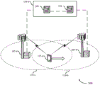
Fig. 2 illustrates an example of a wireless communication system 200 that supports dual link handover in accordance with various aspects of the disclosure. The wireless communication system 200 may include a UE115-a, a source base station 105-a, and a target base station 105-b, which may be examples of the UE115 or base station 105 described herein and with reference to fig. 1. The wireless communication system 200 may include a core network 130-a, which may include an MME205 and an S-GW 210, which may be examples of network components described herein and with reference to fig. 1.
The UE115-a may undergo a dual link handover procedure from the source base station 105-a to the target base station 105-b. For example, the UE115-a may be moving from the geographic coverage area 110-a to the coverage area 110-b. Prior to handover, the UE115-a may have a protocol stack configured for communication with the source base station 105-a. For example, the UE115-a may have RRC, PDCP, RLC, and MAC layer configurations. The UE115-a may refrain from resetting the MAC configuration or re-establishing the PDCP configuration until after performing a successful RACH procedure with the target base station 105-b. This may enable the UE115-a to continue communicating with the source base station 105-a until it is ready to transfer communications to the target base station 105-b. During the final phase of the handover, the MME205 and the P-GW may transfer the EPS bearer for the UE115-a from the source base station 105-a to the target base station 105-b.
In some cases, the handover mechanism may include three steps: first, the source base station 105-a may decide to handover the UE115-a to the target base station 105-b and send a handover command including RRC configuration information of the target base station 105-b to the UE 115-a; second, the UE115-a may apply the new RRC configuration, reset the MAC configuration and initiate PDCP re-establishment; third, the UE115-a may perform a RACH procedure at the target base station 105-b. In accordance with the present disclosure, the UE115-a may continue to receive data and transmit HARQ or CSI feedback with the source base station 105-a. However, in some examples, the UE115-a may suspend RLM measurements for the source base station 105-a during handover. If the RACH fails, the UE115-a may return to the source base station 105-a (and recover the RLM, if appropriate).
In some cases, the source base station 105-a may decide not to handover the UE115-a to the target base station 105-b. For example, the target base station 105-b may indicate to the source base station 105-a (e.g., via the backhaul link) that it does not have dual link handover capability. The source base station 105-a may then refrain from transmitting the handover command based on the indicated capabilities of the target base station 105-b.
In some cases, a single RLC/PDCP stack may be used by the UE115-a during a handover procedure. A successful RACH procedure for the target base station 105-b may be a trigger point for handover RLC/PDCP. This may also trigger the target base station 105-b to indicate to the source base station 105-a to stop transmission of data packets. At this time, a PDCP status report may be transmitted from the UE115-a to the target base station 105-a. In other cases, dual RLC/PDCP may be used and UE115-a may use different protocol stacks to receive data from the two cells during handover.
The source base station 105-a may forward the data to the target base station 105-b after the handover. However, the source base station 105-a may continue to transfer PDCP SDUs to the UE115-a, and a sequence number status report may be sent to the target base station 105-b after the source base station 105-a stops transferring to the UE 115-a. If, for example, dual RLC/PDCP is used, both ciphered and non-ciphered PDCP pdus may be forwarded. The PDCP PDUs may be forwarded (with or without ciphering) when the source base station 105-a receives the marker packet. That is, the target base station 105-b may transmit the source ciphered PDU until it can take over transmission (i.e., after the source base station stops transmitting). The UE115-a may monitor both base stations 105 and may use the same logical channel to receive PDCP PDUs from both base stations 105. If the target base station 105-b transmits some of the same PDCP PDUs during the transition, the duplicate may be received and processed at the UE 115-a.
In some cases, additional signaling between the UE115-a and the source base station 105-a may be used to indicate or negotiate the appropriate handover type. For example, the UE115-a may signal that it is capable of participating in a dual link handover, i.e., it may be capable of communicating with both base stations 105-a during a handover transition period between receiving a handover command from the source base station 105-a and performing a successful RACH with the target base station 105-b. The dual link handover capabilities of both the UE115-a and the source base station 105-a may be exchanged during RRC configuration and this information may be forwarded to the target base station 105-b before or during handover.
In some cases, the dual link handover procedures described herein may be associated with UEs 115 capable of low latency operation. For example, signaling low latency capability may indicate dual link handover capability, or vice versa. Low latency operation may involve communicating using Transmission Time Intervals (TTIs) that are smaller in length than subframes. For example, the TTI may vary from a subframe length to a symbol period length. The use of dual link handover may supplement the latency reduction associated with reduced TTI lengths.
In some cases, the UE115-a may recover the RLM at the source base station 105-a if the access at the target base station 105-b fails. In some cases, signaling from the target base station 105-b to the source base station 105-a may be used to inform the UE115-a that access to the target base station 105-b has been completed. This may be used to inform the source base station 105-a to stop data transmission. In some cases, a forward handover may be used, where the UE115-a makes a decision to handover to the target base station 105-b. In a forward handover or otherwise, the UE115-a may not reset the MAC/PDCP configuration until it successfully completes access to the target base station 105-b.
Fig. 3 illustrates an example of a process flow 300 for a system supporting dual link switching in accordance with various aspects of the present disclosure. Process flow 300 may include UE115-b, which may be an example of UE115 described herein and with reference to fig. 1 and 2. The process flow 300 may also include base stations 105-c, 105-d, MME205-a, and S-GW 210-a, which may be examples of network components described herein and with reference to FIGS. 1-2.
At 305, the UE115-b and the source base station 105-c may establish an RRC configuration. In some cases, the UE115-b may transmit an indication of a dual link handover capability to the source base station 105-c, and the data transmission may be received based at least in part on the indication. In some examples, the dual link switching capability is associated with a low latency capability.
At 310, the UE115-b may, and the source base station 105-c may, perform one or more radio link measurements indicating that the UE115-b may receive better service by transitioning to the target base station 105-d. At 315, the source base station 105-c may send a handover preparation request to the target base station 105-d. The target base station 105-d may acknowledge the handover preparation request 317.
At 320, the source base station 105-c may transmit a handover command (e.g., an RRC reconfiguration message) to the UE 115-b. Thus, the UE115-b may receive a connection reconfiguration message associated with a handover from the source base station 105-c to the target base station 105-d. As used herein, an access procedure may be considered to be any combination of 305-320 within the process flow 300. Further, the UE115-b may determine whether the access procedure was successful or unsuccessful based on the content of the connection reconfiguration message. For example, the connection reconfiguration message may include an information element indicating whether the access procedure was successful. In some cases, UE115-b may suppress the RLM procedure based on receiving the connection reconfiguration message. In some cases, UE115-b may resume the RLM procedure with the source base station based at least in part on determining that the access procedure is unsuccessful. Additionally or alternatively, the UE115-b may resume the RLM procedure with the target base station based at least in part on determining that the access procedure was successful. In some cases, the UE115-b may clear the connection reconfiguration message and continue communication with the source base station 105-c based at least in part on determining that the access procedure is unsuccessful.
At 325, the source base station 105-c may continue to send data transmissions (corresponding to RLC PDUs) to the UE 115-b. The UE115-b may thus receive a data transmission from the source base station 105-c after receiving the connection reconfiguration message.
At 330, the UE115-b may transmit an RRC reconfiguration request (e.g., according to a RACH procedure) to the target base station 105-d. The UE115-b may thus perform a successful access procedure with the target base station 105-d based on receiving the connection reconfiguration message.
At 332, the target base station 105-d may transmit configuration information (such as UL grant information and timing adjustment information) to the UE 115-b. In some examples, performing a successful access procedure includes receiving a contention resolution message from the target base station 105-d.
At 334, the UE115-b may send a connection reconfiguration message associated with the handover to the target base station 105-d. In some cases, the UE115-b may receive a second data transmission from the target base station 105-d before resetting the MAC configuration, resetting the RLC configuration, or re-establishing the PDCP configuration. In some examples, the second data transmission is a source base station encrypted transmission. In some cases, the source base station encrypted transmission may be forwarded by the source base station 105 to the target base station 105 and then sent to the UE 115-b. In some cases, the second data transmission corresponds to the same logical channel as the data transmission from the source base station.
At 335, the UE115-b may reset the MAC and/or RLC configuration or re-establish the PDCP configuration for communication with the target base station 105-d. That is, the UE115-b may reset the MAC configuration, reset the RLC configuration, or re-establish the PDCP configuration, or any combination thereof, based on a successful access procedure.
The target base station 105-d may send a handover execution message to the source base station 105-c at 340. Thus, the source base station 105-c may receive the handover execution message from the target base station 105-d after the UE115-b performs a successful access procedure for the target base station 105-d. The source base station 105-c may stop transmitting subsequent messages to the UE115-b based on receiving the handover execution message.
At 345, the target base station 105-d may send a path switch request to the MME 205-a. At 347, the MME205-a may send a modify bearer request to the S-GW 210-a. At 350, the source base station 105-c may send a Sequence Number (SN) status transfer message to the target base station 105-d. At 352, the source base station 105-c may send EPS bearer data to the target base station 105-d. At 355, the S-GW 210-a may handover the DL path for the UE115-b from the source base station 105-c to the target base station 105-d.
At 360, the target base station 105-d may transmit one or more RLC PDUs to the UE 115-b. Thus, the UE115-b may receive a subsequent data transmission from the target base station 105-d based on the reset MAC configuration, the reset RLC configuration, the re-established PDCP configuration, or any combination thereof. In some examples, the data transmission from the source base station 105-c and the subsequent data transmission from the target base station 105-d use the same RLC/PDCP stack.
The S-GW 210-a may send an end marker to the source base station 105-c at 365. At 367, the source base station 105-c may transmit an end marker to the target base station 105-d. The S-GW 210-a may route packet data for the UE115-b to the target base station 105-d at 370. The S-GW 210-a may send a modify bearer response to the MME205-a at 375. At 377, the MME205-a may send a path switch response to the target base station 105-d. The target base station 105-d may transmit a UE context release message to the source base station 105-c at 380.
Fig. 4 illustrates a block diagram of a wireless device 400 that supports dual link handover in accordance with various aspects of the disclosure. The wireless device 400 may be an example of aspects of the UE115 described with reference to fig. 1-3. The wireless device 400 may include a receiver 405, a dual link switching module 410, or a transmitter 415. The wireless device 400 may also include a processor. Each of these components may be in communication with each other.
The dual link handover module 410 may receive, e.g., in combination with the receiver 405, a connection reconfiguration message associated with a handover from a source base station to a target base station, receive a data transmission from the source base station after receiving the connection reconfiguration message, perform a successful access procedure with the target base station based on receiving the connection reconfiguration message, and reset a MAC configuration, a PDCP configuration, or an RLC configuration based on the successful access procedure.
The transmitter 415 may transmit signals received from other components of the wireless device 400. In some examples, the transmitter 415 may be co-located with the receiver 405 in a transceiver module. The transmitter 415 may include a single antenna, or it may include multiple antennas.
Fig. 5 illustrates a block diagram of a wireless device 500 that supports dual link handover in accordance with various aspects of the disclosure. The wireless device 500 may be an example of aspects of the wireless device 400 or UE115 described with reference to fig. 1-4. The wireless device 500 may include a receiver 405-a, a dual link switching module 410-a, or a transmitter 415-a. The wireless device 500 may also include a processor. Each of these components may be in communication with each other. The dual-link switching module 410-a may also include a connection reconfiguration module 505, a data module 510, an access module 515, and a reconfiguration module 520.
The receiver 405-a may receive information that may be passed to the dual link switching module 410-a and to other components of the wireless device 500. The dual-link handover module 410-a may perform the operations described herein and with reference to fig. 4. The transmitter 415-a may transmit signals received from other components of the wireless device 500.
The connection reconfiguration module 505 may receive a connection reconfiguration message associated with a handover from a source base station to a target base station, as described herein and with reference to fig. 2-3.
The data module 510 may receive a data transmission from the source base station after receiving the connection reconfiguration message, as described herein and with reference to fig. 2-3. The data module 510 may also receive a subsequent data transmission from the target base station based on the reset MAC configuration, the reset RLC configuration, or the re-established PDCP configuration. In some examples, the data transmission and the subsequent data transmission use the same RLC/PDCP stack. The data module 510 may also receive a second data transmission from the target base station before resetting the MAC configuration, resetting the RLC configuration, or re-establishing the PDCP configuration. In some examples, the second data transmission may be a source base station encrypted transmission. Additionally or alternatively, the second data transmission corresponds to the same logical channel as the data transmission from the source base station. The data module 510 may also send a data transmission to the wireless device based on receiving the SN status transfer message or the bearer data message.
The access module 515 may perform an access procedure with the target base station based on receiving the connection reconfiguration message, as described herein and with reference to fig. 2-3. The access module 515 may also determine whether the access procedure was successful. In some examples, performing a successful access procedure includes receiving a contention resolution message from the target base station. The access module 515 may also receive a connection reconfiguration complete message from the wireless device based on the access request.
The reconfiguration module 520 may reset the MAC configuration, reset the RLC configuration or re-establish the PDCP configuration, or all three based on a successful access procedure, as described herein and with reference to fig. 2-3.
Fig. 6 illustrates a block diagram 600 of a dual link switching module 410-b, which dual link switching module 410-b may be a component of a wireless device 400 or a wireless device 500 that supports dual link switching, in accordance with various aspects of the present disclosure. The dual-link switching module 410-b may be an example of aspects of the dual-link switching module 410 described with reference to fig. 4-5. The dual-link switching module 410-b may also include a connection reconfiguration module 505-a, a data module 510-a, an access module 515-a, and a reconfiguration module 520-a. Each of these modules may perform the functions described herein and with reference to fig. 5. The dual-link switching module 410-b may also include a dual-link capability module 605 and an RLM module 610.
The dual link capability module 605 may transmit an indication of a dual link handover capability to the source base station, and the data transmission may be received based at least in part on the indication, as described herein and with reference to fig. 2-3. In some examples, the dual link switching capability may be associated with a low latency capability. The dual link capability module 605 may also send an indication of the dual link handover capability to the target base station. The RLM module 610 may suppress the RLM procedure based on, for example, receiving the connection reconfiguration message, as described herein and with reference to fig. 2-3.
Fig. 7 illustrates a diagram of a system 700 that includes a UE115 that supports dual link handover in accordance with various aspects of the disclosure. System 700 may include UE115-c, which UE115-c may be an example of wireless device 400, wireless device 500, or UE115 described herein and with reference to fig. 1, 2, and 4-6. The UE115-c may include a dual link switching module 710, which dual link switching module 710 may be an example of the dual link switching module 410 described with reference to fig. 4-6. The UE115-c may also include a low latency module 725. UE115-c may also include components for two-way voice and data communications, including components for transmitting communications and components for receiving communications. For example, a UE115-c may communicate bi-directionally with a base station 105-e or a base station 105-f. For example, base station 105-e may be a source base station 105 and base station 105-f may be a target base station 105 during a handover procedure.
The low-latency module 725 may perform low-latency operations or configure the UE115-c for low-latency operations. For example, the low-latency module 725 may support communications using TTI lengths less than LTE subframes. In some examples, the low latency operation may be based on the TTI length of one LTE symbol period.
The UE115-c may also include a processor 705, as well as memory 715, including Software (SW)720, a transceiver 735, and one or more antennas 740, each of which may communicate with each other directly or indirectly (e.g., via a bus 745). The transceiver 735 may be in bidirectional communication with one or more networks via the antenna 740 or a wired or wireless link, as described above. For example, the transceiver 735 may be in bidirectional communication with a base station 105 or another UE 115. The transceiver 735 may include a modem to modulate packets and provide the modulated packets to the antenna 740 for transmission, as well as demodulate packets received from the antenna 740. Although the UE115-c may include a single antenna 740, the UE115-c may also have multiple antennas 740 capable of concurrently transmitting or receiving multiple wireless transmissions.
The memory 715 may include Random Access Memory (RAM) and Read Only Memory (ROM). The memory 715 may store computer-readable, computer-executable software/firmware code 720 including instructions that, when executed, cause the processor 705 to perform various functions described herein (e.g., dual link switching, etc.). Alternatively, the software/firmware code 720 may not be directly executable by the processor 705, but cause the computer (e.g., when compiled and executed) to perform the functions described herein. Processor 705 may include intelligent hardware devices (e.g., Central Processing Unit (CPU), microcontroller, ASIC, etc.).
Fig. 8 illustrates a block diagram of a wireless device 800 that supports dual link handover in accordance with various aspects of the disclosure. The wireless device 800 may be an example of aspects of the base station 105 described with reference to fig. 1-3 and 7. Wireless device 800 may include a receiver 805, a Base Station (BS) dual link handover module 810, or a transmitter 815. The wireless device 800 may also include a processor. Each of these components may be in communication with each other.
The base station dual link handover module 810 may transmit a connection reconfiguration message associated with handover of a wireless device to a target base station, transmit a data transmission to the wireless device after transmitting the connection reconfiguration message, and receive a handover execution message from the target base station or the wireless device after the wireless device performs a successful access procedure for the target base station. In some examples, the base station dual link handover module 810 may receive a handover preparation request from a source base station, receive an access request from a wireless device (e.g., UE), receive a connection reconfiguration complete message from the wireless device, and transmit a handover execution message to the source base station based on the connection reconfiguration complete message. In some examples, the base station dual link handover module 810 may determine that the target base station does not support dual link handover. For example, the source base station dual link handover module 810 may receive an indication of the capabilities of the target base station, which may indicate that the target base station does not have dual link handover capabilities. The base station dual link handover module 810 can suppress transmission of a connection reconfiguration message associated with handover of the wireless device to the target base station based on the determination.
The transmitter 815 may transmit signals received from other components of the wireless device 800. In some examples, the transmitter 815 may be co-located with the receiver 805 in a transceiver module. The transmitter 815 may include a single antenna, or it may include multiple antennas.
Fig. 9 illustrates a block diagram of a wireless device 900 that supports dual link handover in accordance with various aspects of the disclosure. The wireless device 900 may be an example of aspects of the wireless device 800 or the base station 105 described with reference to fig. 1-8. Wireless device 900 may include a receiver 805-a, a base station dual link switching module 810-a, or a transmitter 815-a. The wireless device 900 may also include a processor. Each of these components may be in communication with each other. The base station dual link handover module 810-a may further include a BS connection reconfiguration module 905, a BS data module 910, a handover execution module 915, a handover preparation module 920, and a BS access module 925.
Receiver 805-a may receive information that may be passed to a base station dual link handover module 810-a and to other components of wireless device 900. The base station dual link handover module 810-a may perform the operations described herein and with reference to fig. 8. The transmitter 815-a may transmit signals received from other components of the wireless device 900.
The BS connection reconfiguration module 905 may transmit a connection reconfiguration message associated with a handover of a wireless device to a target base station, as described herein and with reference to fig. 2-3.
The BS data module 910 may send a data transmission to the wireless device after sending the connection reconfiguration message, as described herein and with reference to fig. 2-3.
The handover execution module 915 may receive a handover execution message from the target base station or the wireless device after the wireless device performs a successful access procedure for the target base station, as described herein and with reference to fig. 2-3. The handover execution module 915 may also transmit a handover execution message to the source base station based on the connection reconfiguration complete message.
The handover preparation module 920 may receive a handover preparation request from a source base station as described herein and with reference to fig. 2-3. The BS access module 925 can receive an access request from a wireless device as described herein and with reference to fig. 2-3.
Fig. 10 illustrates a block diagram 1000 of a base station dual link handover module 810-b, which dual link handover module 810-b may be a component of a wireless device 800 or a wireless device 900 that supports dual link handover, in accordance with various aspects of the present disclosure. The base station dual link handover module 810-b may be an example of aspects of the base station dual link handover module 810 described with reference to fig. 8-9. The base station dual link handover module 810-b may include a BS connection reconfiguration module 905-a, a BS data module 910-a, a handover execution module 915-a, a handover preparation module 920-a, and a BS access module 925-a. Each of these modules may perform the functions described herein and with reference to fig. 9. The base station dual link handover module 810-b may also include a BS dual link capability module 1005 and a bearer transfer module 1010.
BS dual link capability module 1005 may receive an indication of dual link handover capability from a wireless device such that a data transmission may be sent based at least in part on the indication, as described herein and with reference to fig. 2-3. The BS dual link capability module 1005 may also transmit an SN status transfer message or a bearer data message to the target base station in response to the handover execution message. In some cases, BS dual link capability module 1005 may transmit a first indication of dual link handover capability to the source base station. The BS dual link capability module 1005 may also receive a second indication of dual link handover capability from the source base station to cause transmission of a data transmission based at least in part on the second indication. In some examples, the dual link switching capability may be associated with a low latency capability.
The bearer transfer module 1010 may receive an SN status transfer message or a bearer data message from the source base station in response to the handover execution message, as described herein and with reference to fig. 2-3.
Fig. 11 illustrates a diagram of a system 1100 that includes a base station 105 that supports dual link handover in accordance with various aspects of the disclosure. System 1100 may include a base station 105-g, which base station 105-g may be an example of wireless device 800, wireless device 900, or base station 105 described herein and with reference to fig. 1, 2, and 8-10. The base station 105-g may include a base station dual link handover module 1110, which may be an example of the base station dual link handover module 810 described with reference to fig. 8-10. The base station 105-g may also include components for two-way voice and data communications, including components for transmitting communications and components for receiving communications. For example, a base station 105-g may communicate bi-directionally with a UE 115-d or a UE 115-e. The base station 105-g may perform both the roles of the source base station 105 or the target base station 105 for different UEs 115.
In some cases, base station 105-g may have one or more wired backhaul links. The base station 105-g may have a wired backhaul link (e.g., S1 interface, etc.) to the core network 130-b. Base station 105-g may also communicate with other base stations 105, such as base station 105-h and base station 105-i, via an inter-base station backhaul link (e.g., an X2 interface). Each base station 105 may communicate with the UE115 using the same or different wireless communication technology. In some cases, base station 105-g may utilize base station communication module 1125 to communicate with other base stations (such as 105-h or 105-i). In some examples, the base station communication module 1125 may provide an X2 interface within the LTE/LTE-a wireless communication network technology to provide communication between some base stations 105. In some examples, base station 105-g may communicate with other base stations through core network 130-b. In some cases, base station 105-g may communicate with core network 130-b through network communication module 1130.
The base station 105-g may include a processor 1105, a memory 1115 (including Software (SW)1120), a transceiver 1135, and an antenna 1140, each of which may be in direct or indirect communication with each other (e.g., via a bus system 1145). The transceiver 1135 may be configured for bidirectional communication with a UE115 (which may be a multi-mode device) via an antenna 1140. The transceiver 1135 (or other components of the base station 105-g) may also be configured to communicate bi-directionally via the antenna 1140 with one or more other base stations (not shown). The transceiver 1135 may include a modem configured to modulate packets and provide the modulated packets to the antenna(s) 1140 for transmission, as well as demodulate packets received from the antenna(s) 1140. The base station 105-g may include multiple transceivers 1135, each having one or more associated antennas 1140. The transceiver may be an example of the combined receiver 805 and transmitter 815 of fig. 8.
The base station communication module 1125 may manage communications with other base stations 105. The communication management module may include a controller or scheduler for controlling communications with the UE115 in cooperation with other base stations 105. For example, the base station communication module 1125 may coordinate scheduling of handover procedures or transmissions to the UE115 for various interference mitigation techniques, such as beamforming or joint transmission.
The components of the wireless device 400, the wireless device 500, the dual link switching module 410, the system 700, the wireless device 800, the wireless device 900, the base station dual link switching module 810-b, and the system 1100 may be implemented individually or collectively using at least one ASIC adapted to perform some or all of the applicable functions in hardware. Alternatively, these functions may be performed by one or more other processing units (or cores), on at least one IC. In other examples, other types of integrated circuits (e.g., structured/platform ASICs, FPGAs, or another half-custom IC) may be used that may be programmed in any manner known in the art. The functions of each unit may also be implemented, in whole or in part, with instructions embodied in a memory, formatted to be executed by one or more general or special purpose processors.
Fig. 12 shows a flow diagram illustrating a method 1200 for dual link handover in accordance with various aspects of the present disclosure. The operations of method 1200 may be implemented by UE115 or components thereof described with reference to fig. 1-11. For example, the operations of method 1200 may be performed by the dual link switching module 410 described with reference to fig. 4-7. In some examples, the UE115 may execute a set of codes for controlling the functional elements of the UE115 to perform the functions described below. Additionally or alternatively, the UE115 may use dedicated hardware to perform aspects of the functions described below.
At block 1205, the UE115 may receive a connection reconfiguration message associated with a handover from a source base station to a target base station, as described herein and with reference to fig. 2-3. In certain examples, the operations of block 1205 may be performed by the connection reconfiguration module 505 described herein and with reference to fig. 5.
At block 1210, the UE115 may receive a data transmission from the source base station after receiving the connection reconfiguration message, as described herein and with reference to fig. 2-3. In certain examples, the operations of block 1210 may be performed by data module 510 as described herein and with reference to fig. 5.
At block 1215, the UE115 may perform an access procedure with the target base station based on receiving the connection reconfiguration message, as described herein and with reference to fig. 2-3. In some examples, the operations of block 1215 may be performed by the access module 515 as described herein and with reference to fig. 5.
At block 1220, the UE115-b may determine whether the access procedure was successful, as described herein and with reference to fig. 2-3. In certain examples, the operations of block 1220 may be performed by the access module 515 as described herein and with reference to fig. 5.
At block 1225, the UE115 may reset the MAC configuration, reset the RLC configuration, or re-establish the PDCP configuration, or any combination thereof, based on the successful access procedure, as described herein and with reference to fig. 2-3. In certain examples, the operations of block 1225 may be performed by reconfiguration module 520 as described herein and with reference to fig. 5.
Fig. 13 shows a flow diagram illustrating a method 1300 for dual link handover in accordance with various aspects of the present disclosure. The operations of method 1300 may be implemented by UE115 or components thereof described with reference to fig. 1-11. For example, the operations of method 1300 may be performed by dual link switching module 410 described with reference to fig. 4-7. In some examples, the UE115 may execute a set of codes for controlling the functional elements of the UE115 to perform the functions described below. Additionally or alternatively, the UE115 may use dedicated hardware to perform aspects of the functions described below. Method 1300 may also incorporate aspects of method 1200 of fig. 12.
At block 1305, the UE115 may transmit an indication of the dual link handover capability to the source base station such that a data transmission may be received after the handover command based at least in part on the indication, as described herein and with reference to fig. 2-3. In certain examples, the operations of block 1305 may be performed by the dual link capability module 605 described herein and with reference to fig. 6.
At block 1310, the UE115 may receive a connection reconfiguration message associated with a handover from a source base station to a target base station, as described herein and with reference to fig. 2-3. In certain examples, the operations of block 1310 may be performed by the connection reconfiguration module 505 described herein and with reference to fig. 5.
At block 1315, the UE115 may receive a data transmission from the source base station after receiving the connection reconfiguration message, as described herein and with reference to fig. 2-3. In certain examples, the operations of block 1315 may be performed by data module 510 as described herein and with reference to fig. 5.
At block 1320, the UE115 may perform a successful access procedure with the target base station based on receiving the connection reconfiguration message, as described herein and with reference to fig. 2-3. In certain examples, the operations of block 1320 may be performed by the access module 515 as described herein and with reference to fig. 5.
At block 1325, the UE115-b may determine whether the access procedure was successful, as described herein and with reference to fig. 2-3. In certain examples, the operations of block 1325 may be performed by access module 515 as described herein and with reference to fig. 5.
At block 1330, the UE115 may reset the MAC configuration, reset the RLC configuration, or re-establish the PDCP configuration, or any combination thereof, based on the successful access procedure, as described herein and with reference to fig. 2-3. In certain examples, the operations of block 1330 may be performed by the reconfiguration module 520 as described herein and with reference to fig. 5.
Fig. 14 shows a flow diagram illustrating a method 1400 for dual link handover in accordance with various aspects of the present disclosure. The operations of the method 1400 may be implemented by the UE115 described with reference to fig. 1-11, or components thereof. For example, the operations of the method 1400 may be performed by the dual link switching module 410 described with reference to fig. 4-7. In some examples, the UE115 may execute a set of codes for controlling the functional elements of the UE115 to perform the functions described below. Additionally or alternatively, the UE115 may use dedicated hardware to perform aspects of the functions described below. Method 1400 may also incorporate aspects of methods 1200 and 1300 of fig. 12-13.
At block 1405, the UE115 may receive a connection reconfiguration message associated with a handover from a source base station to a target base station, as described herein and with reference to fig. 2-3. In certain examples, the operations of block 1405 may be performed by the connection reconfiguration module 505 described herein and with reference to fig. 5.
At block 1410, the UE115 may receive a data transmission from the source base station after receiving the connection reconfiguration message, as described herein and with reference to fig. 2-3. In certain examples, the operations of block 1410 may be performed by data module 510 as described herein and with reference to fig. 5.
At block 1415, the UE115 may perform an access procedure with the target base station based on receiving the connection reconfiguration message, as described herein and with reference to fig. 2-3. In certain examples, the operations of block 1415 may be performed by the access module 515 as described herein and with reference to fig. 5.
At block 1420, the UE115-b may determine whether the access procedure was successful, as described herein and with reference to fig. 2-3. In certain examples, the operations of block 1420 may be performed by the access module 515 as described herein and with reference to fig. 5.
At block 1425, the UE115 may reset the MAC configuration, reset the RLC configuration, re-establish the PDCP configuration, or any combination thereof based on the successful access procedure, as described herein and with reference to fig. 2-3. In certain examples, the operations of block 1425 may be performed by the reconfiguration module 520 as described herein and with reference to fig. 5.
At block 1430, the UE115 may receive a subsequent data transmission from the target base station based on the reset MAC configuration, the reset RLC configuration, the re-established PDCP configuration, or any combination thereof, as described herein and with reference to fig. 2-3. In certain examples, the operations of block 1430 may be performed by the data module 510 as described herein and with reference to fig. 5.
Fig. 15 shows a flow diagram illustrating a method 1500 for dual link handover in accordance with various aspects of the present disclosure. The operations of the method 1500 may be implemented by the base station 105 described with reference to fig. 1-11, or components thereof. For example, the operations of method 1500 may be performed by base station dual link handover module 810 described with reference to fig. 8-11. In some examples, the base station 105 may execute a set of codes for controlling the functional elements of the base station 105 to perform the functions described below. Additionally or alternatively, the base station 105 may use dedicated hardware to perform aspects of the functions described below. Method 1500 may also incorporate aspects of methods 1200, 1300, and 1400 of fig. 12-14.
At block 1505, the base station 105 may transmit a connection reconfiguration message associated with a handover of the wireless device to a target base station, as described herein and with reference to fig. 2-3. In certain examples, the operations of block 1505 may be performed by the BS connection reconfiguration module 905 described herein and with reference to fig. 9.
At block 1510, the base station 105 may send a data transmission to the wireless device after sending the connection reconfiguration message, as described herein and with reference to fig. 2-3. In certain examples, the operations of block 1510 may be performed by the BS data module 910 as described herein and with reference to fig. 9.
At block 1515, the base station 105 may receive a handover execution message from the target base station or the wireless device after the wireless device performs a successful access procedure for the target base station, as described herein and with reference to fig. 2-3. In certain examples, the operations of block 1515 may be performed by the handover execution module 915 as described herein and with reference to fig. 9.
Fig. 16 shows a flow diagram illustrating a method 1600 for dual link handover in accordance with various aspects of the present disclosure. The operations of method 1600 may be implemented by base station 105 or components thereof described with reference to fig. 1-11. For example, the operations of method 1600 may be performed by base station dual link handover module 810 described with reference to fig. 8-11. In some examples, the base station 105 may execute a set of codes for controlling the functional elements of the base station 105 to perform the functions described below. Additionally or alternatively, the base station 105 may use dedicated hardware to perform aspects of the functions described below. Method 1600 may also incorporate aspects of methods 1200, 1300, 1400, and 1500 of fig. 12-15.
At block 1605, the base station 105 may receive an indication of the dual link handover capability from the wireless device such that a data transmission may be sent based at least in part on the indication, as described herein and with reference to fig. 2-3. In certain examples, the operations of block 1605 may be performed by BS dual link capability module 1005 described herein and with reference to fig. 10.
At block 1610, the base station 105 may transmit a connection reconfiguration message associated with a handover of the wireless device to a target base station, as described herein and with reference to fig. 2-3. In certain examples, the operations of block 1610 may be performed by the BS connection reconfiguration module 905 described herein and with reference to fig. 9.
At block 1615, the base station 105 may send a data transmission to the wireless device after sending the connection reconfiguration message, as described herein and with reference to fig. 2-3. In certain examples, the operations of block 1615 may be performed by the BS data module 910 as described herein and with reference to fig. 9.
At block 1620, the base station 105 may receive a handover execution message from the target base station or the wireless device after the wireless device performs a successful access procedure for the target base station, as described herein and with reference to fig. 2-3. In some examples, the operations of block 1620 may be performed by handover execution module 915 as described herein and with reference to fig. 9.
Fig. 17 shows a flow diagram illustrating a method 1700 for dual link handover in accordance with various aspects of the present disclosure. The operations of the method 1700 may be implemented by the base station 105 described with reference to fig. 1-11, or components thereof. For example, the operations of method 1700 may be performed by base station dual link handover module 810 described with reference to fig. 8-11. In some examples, the base station 105 may execute a set of codes for controlling the functional elements of the base station 105 to perform the functions described below. Additionally or alternatively, the base station 105 may use dedicated hardware to perform aspects of the functions described below. Method 1700 may also incorporate aspects of methods 1200, 1300, 1400, 1500, and 1600 of fig. 12-16.
At block 1705, the base station 105 may receive a handover preparation request from a source base station, as described herein and with reference to fig. 2-3. In certain examples, the operations of block 1705 may be performed by handover preparation module 920 as described herein and with reference to fig. 9.
At block 1710, the base station 105 may receive an access request from a wireless device, as described herein and with reference to fig. 2-3. In certain examples, the operations of block 1710 may be performed by the BS access module 925 as described herein and with reference to fig. 9.
At block 1715, the base station 105 may receive a connection reconfiguration complete message from the wireless device based on the access request, as described herein and with reference to fig. 2-3. In certain examples, the operations of block 1715 may be performed by the access module 515 as described herein and with reference to fig. 5.
At block 1720, the base station 105 may transmit a handover execution message to the source base station based on the connection reconfiguration complete message, as described herein and with reference to fig. 2-3. In certain examples, the operations of block 1720 may be performed by handover execution module 915 as described herein and with reference to fig. 9.
Thus, methods 1200, 1300, 1400, 1500, 1600, and 1700 may support dual link switching. It should be noted that methods 1200, 1300, 1400, 1500, 1600, and 1700 describe possible implementations, and that these operations and steps may be rearranged or otherwise modified such that other implementations are possible. In some examples, aspects from two or more of methods 1200, 1300, 1400, 1500, 1600, and 1700 may be combined.
The description herein provides examples and does not limit the scope, applicability, or examples set forth in the claims. Changes may be made in the function and arrangement of elements discussed without departing from the scope of the disclosure. Various examples may omit, substitute, or add various procedures or components as appropriate. For example, the described methods may be performed in an order different than described, and various steps may be added, omitted, or combined. Additionally, features described with reference to some examples may be combined in other examples.
The techniques described herein may be used for various wireless communication systems such as Code Division Multiple Access (CDMA), Time Division Multiple Access (TDMA), Frequency Division Multiple Access (FDMA), Orthogonal Frequency Division Multiple Access (OFDMA), single carrier frequency division multiple access (SC-FDMA), and others. The terms "system" and "network" are often used interchangeably. A CDMA system may implement a radio technology such as CDMA2000, Universal Terrestrial Radio Access (UTRA), and so on. CDMA2000 covers IS-2000, IS-95 and IS-856 standards. IS-2000 releases 0 and A are often referred to as CDMA20001X, 1X, etc. IS-856(TIA-856) IS often referred to as CDMA20001xEV-DO, High Rate Packet Data (HRPD), etc. UTRA includes wideband CDMA (wcdma) and other CDMA variants. TDMA systems may implement radio technologies such as global system for mobile communications (GSM). OFDMA systems may implement radio technologies such as Ultra Mobile Broadband (UMB), evolved UTRA (E-UTRA), IEEE 802.11(Wi-Fi), IEEE 802.16(WiMAX), IEEE 802.20, Flash-OFDM, etc. UTRA and E-UTRA are parts of the Universal Mobile Telecommunications System (UMTS). 3GPP Long Term Evolution (LTE) and LTE-advanced (LTE-A) are new Universal Mobile Telecommunications System (UMTS) releases that use E-UTRA. UTRA, E-UTRA, UMTS, LTE-A, and Global System for Mobile communications (GSM) are described in literature from an organization named "third Generation partnership project" (3 GPP). CDMA2000 and UMB are described in documents from an organization named "third generation partnership project 2" (3GPP 2). The techniques described herein may be used for both the above-mentioned systems and radio technologies, as well as for other systems and radio technologies. However, the description herein describes an LTE system for purposes of example, and LTE terminology is used in much of the description above, but the techniques may also be applied to applications other than LTE applications.
In LTE/LTE-a networks, including such networks described herein, the term evolved node B (eNB) may be used generically to describe a base station. A wireless communication system or system described herein may include a heterogeneous LTE/LTE-a network in which different types of enbs provide coverage for various geographic regions. For example, each eNB or base station may provide communication coverage for a macro cell, a small cell, or other type of cell. The term "cell" is a 3GPP term that can be used to describe a base station, a carrier or component carrier associated with a base station, or a coverage area (e.g., sector, etc.) of a carrier or base station, depending on the context.
A base station may include, or may be referred to by those skilled in the art as, a base transceiver station, a radio base station, an access point, a radio transceiver, a node B, an evolved node B (eNB), a home node B, a home evolved node B, or some other suitable terminology. The geographic coverage area of a base station may be partitioned into sectors that form only a portion of the coverage area. One or several wireless communication systems described herein may include different types of base stations (e.g., macro or small cell base stations). The UEs described herein may be capable of communicating with various types of base stations and network equipment, including macro enbs, small cell enbs, relay base stations, and the like. There may be overlapping geographic coverage areas of different technologies.
A macro cell generally covers a relatively large geographic area (e.g., an area with a radius of several kilometers) and may allow unrestricted access by UEs with service subscriptions with the network provider. Small cells are low power base stations that may operate in the same or different (e.g., licensed, unlicensed, etc.) frequency bands as macro cells as compared to macro cells. According to various examples, a small cell may include a picocell, a femtocell, and a microcell. Picocells, for example, may cover a small geographic area and may allow unrestricted access by UEs with service subscriptions with the network provider. A femtocell may also cover a smaller geographic area (e.g., a residence) and may be provided access restricted by UEs associated with the femtocell (e.g., UEs in a Closed Subscriber Group (CSG), UEs of users in the residence, etc.). The eNB for a macro cell may be referred to as a macro eNB. An eNB for a small cell may be referred to as a small cell eNB, pico eNB, femto eNB, or home eNB. An eNB may support one or more (e.g., two, three, four, etc.) cells (e.g., component carriers). The UE may be capable of communicating with various types of base stations and network equipment, including macro enbs, small cell enbs, relay base stations, and the like.
One or more of the wireless communication systems described herein may support synchronous or asynchronous operation. For synchronous operation, each base station may have similar frame timing, and transmissions from different base stations may be approximately aligned in time. For asynchronous operation, the base stations may have different frame timings, and transmissions from different base stations may not be aligned in time. The techniques described herein may be used for synchronous or asynchronous operations.
The downlink transmissions described herein may also be referred to as forward link transmissions, while the uplink transmissions may also be referred to as reverse link transmissions. Each of the communication links described herein, including, for example, the wireless communication systems 100 and 200 of fig. 1 and 2, may include one or more carriers, where each carrier may be a signal (e.g., a waveform signal of a different frequency) made up of a plurality of subcarriers. Each modulated signal may be sent on a different subcarrier and may carry control information (e.g., reference signals, control channels, etc.), overhead information, user data, and so on. Communication links described herein (e.g., communication link 125 of fig. 1) may communicate bidirectional communications using Frequency Division Duplex (FDD) operation (e.g., using paired spectrum resources) or Time Division Duplex (TDD) operation (e.g., using unpaired spectrum resources). A frame structure (e.g., frame structure type 1) for FDD and a frame structure (e.g., frame structure type 2) for TDD may be defined.
The illustrations set forth herein in connection with the figures describe example configurations and are not intended to represent all examples that may be implemented or fall within the scope of the claims. The term "exemplary" as used herein means "serving as an example, instance, or illustration," and does not mean "preferred" or "advantageous over other examples. The detailed description includes specific details to provide an understanding of the described technology. However, the techniques may be practiced without these specific details. In some instances, well-known structures and devices are shown in block diagram form in order to avoid obscuring the concepts of the described examples.
In the drawings, similar components or features may have the same reference numerals. Further, various components of the same type may be distinguished by following the reference label by a dash and a second label that distinguishes among the similar components. If only the first reference label is used in the specification, the description is applicable to any one of the similar components having the same first reference label irrespective of the second reference label.
Information and signals described herein may be represented using any of a variety of different technologies and techniques. For example, data, instructions, commands, information, signals, bits, symbols, and chips that may be referenced throughout the above description may be represented by voltages, currents, electromagnetic waves, magnetic fields or particles, optical fields or particles, or any combination thereof.
The various illustrative blocks and modules described in connection with the disclosure herein may be implemented or performed with a general purpose processor, a DSP, an ASIC, an FPGA or other programmable logic device, discrete gate or transistor logic, discrete hardware components, or any combination thereof designed to perform the functions described herein. A general purpose processor may be a microprocessor, but in the alternative, the processor may be any conventional processor, controller, microcontroller, or state machine. A processor may also be implemented as a combination of computing devices (e.g., a combination of a DSP and a microprocessor, a plurality of microprocessors, one or more microprocessors in conjunction with a DSP core, or any other such configuration).
The functions described herein may be implemented in hardware, software executed by a processor, firmware, or any combination thereof. If implemented in software executed by a processor, the functions may be stored on or transmitted over as one or more instructions or code on a computer-readable medium. Other examples and implementations are within the scope of the disclosure and the following claims. For example, due to the nature of software, the functions described above may be implemented using software executed by a processor, hardware, firmware, hard-wired, or any combination thereof. Features that implement functions may also be physically located at various locations, including being distributed such that portions of functions are implemented at different physical locations. As used herein, including in the claims, the terms and/or used in a list of two or more items means that any of the listed items can be employed alone or any combination of the two or more listed items can be employed. For example, if a composition is described as comprising component A, B and/or C, the composition may comprise only a; only B; only C; a combination of A and B; a combination of A and C; a combination of B and C; or a combination of A, B and C. Also, as used herein, including in the claims, "or" as used in a list of items (e.g., a list of items prefaced by a phrase such as "at least one of" or "one or more of" indicates an inclusive list, such that, for example, a phrase referring to "at least one of A, B or C" is intended to cover A, B, C, A-B, A-C, B-C, and A-B-C, as well as any combination of elements in common (e.g., A-A, A-A-A, A-A-B, A-A-C, A-B-B, A-C-C, B-B, B-B-B, B-B-C, C-C, and C-C-C, or A, B, C, or C, Any other ordering of B and C).
As used herein, the phrase "based on" should not be read as referring to a closed condition set. For example, an exemplary step described as "based on condition a" may be based on both condition a and condition B without departing from the scope of the present disclosure. In other words, as used herein, the phrase "based on" should be interpreted in the same manner as the phrase "based at least in part on".
All structural and functional equivalents to the elements of the various aspects described throughout this disclosure that are known or later come to be known to those of ordinary skill in the art are expressly incorporated herein by reference and are intended to be encompassed by the claims. Moreover, nothing disclosed herein is intended to be dedicated to the public regardless of whether such disclosure is explicitly recited in the claims. The terms "module," mechanism, "" element, "" device, "and the like may not be a substitute for the term" means. As such, no claim element should be construed as a means-plus-function unless the element is explicitly recited using the phrase "means for … …".
Computer-readable media includes both non-transitory computer storage media and communication media, including any medium that facilitates transfer of a computer program from one place to another. Non-transitory storage media may be any available media that can be accessed by a general purpose or special purpose computer. By way of example, and not limitation, non-transitory computer-readable media can comprise RAM, ROM, electrically erasable programmable read-only memory (EEPROM), Compact Disk (CD) ROM or other optical disk storage, magnetic disk storage or other magnetic storage devices, or any other non-transitory medium that can be used to carry or store desired program code means in the form of instructions or data structures and that can be accessed by a general-purpose or special-purpose computer, or a general-purpose or special-purpose processor. Any connection is properly termed a computer-readable medium. For example, if the software is transmitted from a web site, server, or other remote source using a coaxial cable, fiber optic cable, twisted pair, Digital Subscriber Line (DSL), or wireless technologies such as infrared, radio, and microwave, then the coaxial cable, fiber optic cable, twisted pair, DSL, or wireless technologies such as infrared, radio, and microwave are included in the definition of medium. Disk (disk) and disc (disc), as used herein, includes CD, laser disc, optical disc, Digital Versatile Disc (DVD), floppy disk and blu-ray disc where disks usually reproduce data magnetically, while discs reproduce data optically with lasers. Combinations of the above are also included within the scope of computer-readable media.
The description herein is provided to enable any person skilled in the art to make or use the present disclosure. Various modifications to the disclosure will be readily apparent to those skilled in the art, and the generic principles defined herein may be applied to other variations without departing from the scope of the disclosure. Thus, the disclosure is not intended to be limited to the examples and designs described herein but is to be accorded the widest scope consistent with the principles and novel features disclosed herein.
Claims (48)
1. A method of wireless communication, comprising:
receiving a connection reconfiguration message associated with a handover from a source base station to a target base station, wherein the connection reconfiguration message includes radio resource control, RRC, configuration information of the target base station;
applying an RRC configuration based at least in part on the received connection reconfiguration message;
receiving a data transmission from the source base station after receiving the connection reconfiguration message;
performing an access procedure with the target base station based at least in part on receiving the connection reconfiguration message;
determining whether the access procedure is successful; and
resetting a Medium Access Control (MAC) configuration, resetting a Radio Link Control (RLC) configuration, or reestablishing a Packet Data Convergence Protocol (PDCP) configuration, or any combination thereof, based at least in part on a successful access procedure.
2. The method of claim 1, further comprising:
transmitting an indication of dual link handover capability to the source base station, wherein the data transmission is received based at least in part on the indication.
3. The method of claim 2, wherein the dual link handover capability is associated with a low latency capability.
4. The method of claim 1, further comprising:
receiving a subsequent data transmission from the target base station based at least in part on the reset MAC configuration, the reset RLC configuration, the re-established PDCP configuration, or any combination thereof.
5. The method of claim 4, wherein the data transmission and the subsequent data transmission use the same RLC/PDCP stack.
6. The method of claim 1, further comprising:
receiving a second data transmission from the target base station prior to resetting the MAC configuration, resetting the RLC configuration, or re-establishing a PDCP configuration, or any combination thereof.
7. The method of claim 6, wherein the second data transmission is a source base station encrypted transmission.
8. The method of claim 6, wherein the second data transmission corresponds to a same logical channel as the data transmission from the source base station.
9. The method of claim 1, further comprising:
refraining from a Radio Link Monitoring (RLM) procedure based at least in part on receiving the connection reconfiguration message.
10. The method of claim 9, further comprising:
recovering a RLM procedure with the source base station based at least in part on determining that the access procedure is unsuccessful.
11. The method of claim 9, further comprising:
resuming an RLM procedure with the target base station based at least in part on determining that the access procedure is successful.
12. The method of claim 1, further comprising:
clearing the connection reconfiguration message based at least in part on determining that the access procedure is unsuccessful; and
continuing communication with the source base station.
13. The method of claim 1, wherein determining that the access procedure is successful comprises:
a contention resolution message is received from the target base station.
14. A method of wireless communication at a source base station, comprising:
transmitting, by the source base station, a radio resource control, RRC, connection reconfiguration message associated with handover of a wireless device to a target base station, wherein the RRC connection reconfiguration message includes RRC configuration information of the target base station;
transmitting a data transmission to the wireless device after transmitting the RRC connection reconfiguration message; and
receiving a handover execution message from the target base station or the wireless device after the wireless device performs a successful access procedure for the target base station.
15. The method of claim 14, further comprising:
receiving an indication of dual link switching capability from the wireless device, wherein the data transmission is sent based at least in part on the indication.
16. The method of claim 15, wherein the dual link handover capability is associated with a low latency capability.
17. The method of claim 15, further comprising:
sending an indication of the dual link handover capability to the target base station.
18. The method of claim 14, further comprising:
ceasing transmission to the wireless device in response to receiving the handover execution message.
19. The method of claim 14, further comprising:
transmitting a Sequence Number (SN) status transfer message or a bearer data message to the target base station in response to the handover execution message.
20. An apparatus for wireless communication, comprising:
means for receiving a connection reconfiguration message associated with a handover from a source base station to a target base station, wherein the connection reconfiguration message includes radio resource control, RRC, configuration information of the target base station;
means for applying an RRC configuration based at least in part on the received connection reconfiguration message;
means for receiving a data transmission from the source base station after receiving the connection reconfiguration message;
means for performing an access procedure with the target base station based at least in part on receiving the connection reconfiguration message;
means for determining whether the access procedure is successful; and
means for resetting a Medium Access Control (MAC) configuration, resetting a Radio Link Control (RLC) configuration, or re-establishing a Packet Data Convergence Protocol (PDCP) configuration, or any combination thereof, based at least in part on a successful access procedure.
21. The apparatus of claim 20, further comprising:
means for transmitting an indication of dual link handover capability to the source base station, wherein the data transmission is received based at least in part on the indication.
22. The apparatus of claim 21, wherein the dual link handover capability is associated with a low latency capability.
23. The apparatus of claim 20, further comprising:
means for receiving a subsequent data transmission from the target base station based at least in part on the reset MAC configuration, the reset RLC configuration, the re-established PDCP configuration, or any combination thereof.
24. The apparatus of claim 23, wherein the data transmission and the subsequent data transmission use a same RLC/PDCP stack.
25. An apparatus for wireless communication at a source base station, comprising:
means for transmitting, by the source base station, a radio resource control, RRC, connection reconfiguration message associated with handover of a wireless device to a target base station, wherein the RRC connection reconfiguration message includes RRC configuration information of the target base station;
means for transmitting a data transmission to the wireless device after transmitting the RRC connection reconfiguration message; and
means for receiving a handover execution message from the target base station or the wireless device after the wireless device performs a successful access procedure for the target base station.
26. The apparatus of claim 25, further comprising:
means for receiving an indication of dual link switching capability from the wireless device, wherein the data transmission is sent based at least in part on the indication.
27. The apparatus of claim 26, wherein the dual link handover capability is associated with a low latency capability.
28. The apparatus of claim 26, further comprising:
means for transmitting an indication of the dual link handover capability to the target base station.
29. The apparatus of claim 25, further comprising:
means for transmitting a Sequence Number (SN) status transfer message or a bearer data message to the target base station in response to the handover execution message.
30. The apparatus of claim 25, further comprising:
means for stopping transmission to the wireless device in response to receiving the handover execution message.
31. An apparatus for wireless communication, comprising:
a processor;
a memory in electronic communication with the processor; and
instructions stored in the memory and executable by the processor to cause the apparatus to:
receiving a connection reconfiguration message associated with a handover from a source base station to a target base station, wherein the connection reconfiguration message includes radio resource control, RRC, configuration information of the target base station;
applying an RRC configuration based at least in part on the received connection reconfiguration message;
receiving a data transmission from the source base station after receiving the connection reconfiguration message;
performing an access procedure with the target base station based at least in part on receiving the connection reconfiguration message;
determining whether the access procedure is successful; and
resetting a Medium Access Control (MAC) configuration, resetting a Radio Link Control (RLC) configuration, or reestablishing a Packet Data Convergence Protocol (PDCP) configuration, or any combination thereof, based at least in part on a successful access procedure.
32. The apparatus of claim 31, wherein the instructions are executable by the processor to cause the apparatus to:
transmitting an indication of dual link handover capability to the source base station; and
receiving the data transmission based at least in part on the indication.
33. The apparatus of claim 32, wherein the dual link handover capability is associated with a low latency capability.
34. The apparatus of claim 31, wherein the instructions are executable by the processor to cause the apparatus to:
receiving a subsequent data transmission from the target base station based at least in part on the reset MAC configuration, the reset RLC configuration, the re-established PDCP configuration, or any combination thereof.
35. The apparatus of claim 34, wherein the data transmission and the subsequent data transmission use a same RLC/PDCP stack.
36. The apparatus of claim 31, wherein the instructions are executable by the processor to cause the apparatus to:
receiving a second data transmission from the target base station prior to resetting the MAC configuration, resetting the RLC configuration, or re-establishing a PDCP configuration, or any combination thereof.
37. The apparatus of claim 36, wherein the second data transmission is a source base station encrypted transmission.
38. The apparatus of claim 36, wherein the second data transmission corresponds to a same logical channel as a data transmission from the source base station.
39. The apparatus of claim 31, wherein the instructions are executable by the processor to cause the apparatus to:
refraining from a Radio Link Monitoring (RLM) procedure based at least in part on receiving the connection reconfiguration message.
40. The apparatus of claim 31, wherein the instructions are executable by the processor to cause the apparatus to:
receiving a contention resolution message from the target base station; and
determining that the access procedure is successful based at least in part on the contention resolution message.
41. An apparatus for wireless communication at a source base station, comprising:
a processor;
a memory in electronic communication with the processor; and
instructions stored in the memory and executable by the processor to cause the apparatus to:
transmitting a radio resource control, RRC, connection reconfiguration message associated with a handover of a wireless device to a target base station, wherein the RRC connection reconfiguration message includes RRC configuration information of the target base station;
transmitting a data transmission to the wireless device after transmitting the RRC connection reconfiguration message; and
receiving a handover execution message from the target base station or the wireless device after the wireless device performs a successful access procedure for the target base station.
42. The apparatus of claim 41, wherein the instructions are executable by the processor to cause the apparatus to:
receiving an indication of dual link handover capability from the wireless device; and
sending the data transmission based at least in part on the indication.
43. The apparatus of claim 42, wherein the dual link handover capability is associated with a low latency capability.
44. The apparatus of claim 42, wherein the instructions are executable by the processor to cause the apparatus to:
sending an indication of the dual link handover capability to the target base station.
45. The apparatus of claim 42, wherein the instructions are executable by the processor to cause the apparatus to:
ceasing transmission to the wireless device in response to receiving the handover execution message.
46. The apparatus of claim 41, wherein the instructions are operable to cause:
transmitting a Sequence Number (SN) status transfer message or a bearer data message to the target base station in response to the handover execution message.
47. A non-transitory computer-readable medium storing code for wireless communication, the code comprising instructions executable to:
receiving a connection reconfiguration message associated with a handover from a source base station to a target base station, wherein the connection reconfiguration message includes radio resource control, RRC, configuration information of the target base station;
applying an RRC configuration based at least in part on the received connection reconfiguration message;
receiving a data transmission from the source base station after receiving the connection reconfiguration message;
performing an access procedure with the target base station based at least in part on receiving the connection reconfiguration message;
determining whether the access procedure is successful; and
resetting a Medium Access Control (MAC) configuration, resetting a Radio Link Control (RLC) configuration, or reestablishing a Packet Data Convergence Protocol (PDCP) configuration, or any combination thereof, based at least in part on a successful access procedure.
48. A non-transitory computer-readable medium storing code for wireless communication at a source base station, the code comprising instructions executable to:
transmitting, by the source base station, a radio resource control, RRC, connection reconfiguration message associated with handover of a wireless device to a target base station, wherein the RRC connection reconfiguration message includes RRC configuration information of the target base station;
transmitting a data transmission to the wireless device after transmitting the RRC connection reconfiguration message; and
receiving a handover execution message from the target base station or the wireless device after the wireless device performs a successful access procedure for the target base station.
Priority Applications (1)
| Application Number | Priority Date | Filing Date | Title |
|---|---|---|---|
| CN202010836927.4A CN111954277B (en) | 2015-03-04 | 2016-02-02 | Dual link handover |
Applications Claiming Priority (5)
| Application Number | Priority Date | Filing Date | Title |
|---|---|---|---|
| US201562128094P | 2015-03-04 | 2015-03-04 | |
| US62/128,094 | 2015-03-04 | ||
| US15/012,062 US10244444B2 (en) | 2015-03-04 | 2016-02-01 | Dual link handover |
| US15/012,062 | 2016-02-01 | ||
| PCT/US2016/016162 WO2016140757A1 (en) | 2015-03-04 | 2016-02-02 | Dual link handover |
Related Child Applications (1)
| Application Number | Title | Priority Date | Filing Date |
|---|---|---|---|
| CN202010836927.4A Division CN111954277B (en) | 2015-03-04 | 2016-02-02 | Dual link handover |
Publications (2)
| Publication Number | Publication Date |
|---|---|
| CN107409336A CN107409336A (en) | 2017-11-28 |
| CN107409336B true CN107409336B (en) | 2020-09-01 |
Family
ID=55353349
Family Applications (2)
| Application Number | Title | Priority Date | Filing Date |
|---|---|---|---|
| CN201680012723.0A Active CN107409336B (en) | 2015-03-04 | 2016-02-02 | Dual link handover |
| CN202010836927.4A Active CN111954277B (en) | 2015-03-04 | 2016-02-02 | Dual link handover |
Family Applications After (1)
| Application Number | Title | Priority Date | Filing Date |
|---|---|---|---|
| CN202010836927.4A Active CN111954277B (en) | 2015-03-04 | 2016-02-02 | Dual link handover |
Country Status (10)
| Country | Link |
|---|---|
| US (3) | US10244444B2 (en) |
| EP (1) | EP3266246B1 (en) |
| JP (2) | JP6577045B2 (en) |
| KR (2) | KR102161943B1 (en) |
| CN (2) | CN107409336B (en) |
| BR (1) | BR112017018959B1 (en) |
| ES (1) | ES2802464T3 (en) |
| HU (1) | HUE049095T2 (en) |
| TW (2) | TWI695648B (en) |
| WO (1) | WO2016140757A1 (en) |
Families Citing this family (77)
| Publication number | Priority date | Publication date | Assignee | Title |
|---|---|---|---|---|
| WO2016004599A1 (en) * | 2014-07-10 | 2016-01-14 | 华为技术有限公司 | Data transmission method, system and related device |
| US10244444B2 (en) * | 2015-03-04 | 2019-03-26 | Qualcomm Incorporated | Dual link handover |
| US11700555B2 (en) * | 2015-08-14 | 2023-07-11 | Qualcomm Incorporated | Mobility design for eMTC |
| CN107637129B (en) * | 2015-09-10 | 2021-07-20 | Oppo 广东移动通信有限公司 | Method and device for channel measurement and measurement result reporting |
| WO2017138977A1 (en) * | 2016-02-12 | 2017-08-17 | Intel IP Corporation | Systems and methods for reducing interruptions in data transmissions due to handover operations |
| CN113423124B (en) | 2016-04-01 | 2023-10-13 | 北京三星通信技术研究有限公司 | Method for supporting seamless switching and base station equipment |
| CN110995773B (en) * | 2016-05-24 | 2021-01-05 | 华为技术有限公司 | QoS control method and device |
| EP3527001A4 (en) * | 2016-10-11 | 2020-06-03 | Telefonaktiebolaget LM Ericsson (publ) | Data transmission during handover |
| US10979944B2 (en) * | 2016-11-14 | 2021-04-13 | Apple Inc. | Dynamic protocol stack reset during radio handover |
| CN109417741B (en) * | 2016-11-16 | 2021-01-29 | 华为技术有限公司 | Data migration method and device |
| CN108243468B (en) * | 2016-12-23 | 2021-09-21 | 夏普株式会社 | User mobility method and device |
| CN108282859B (en) * | 2017-01-06 | 2020-10-27 | 华为技术有限公司 | Communication method and device |
| WO2018130968A1 (en) * | 2017-01-11 | 2018-07-19 | Telefonaktiebolaget Lm Ericsson (Publ) | 5g qos flow to radio bearer remapping |
| EP3826361A1 (en) * | 2017-01-16 | 2021-05-26 | Telefonaktiebolaget LM Ericsson (publ) | Link switch in a wireless communication system |
| US10292081B2 (en) * | 2017-02-03 | 2019-05-14 | Lg Electronics Inc. | Method and apparatus for performing partial handover for continuous data transmission in wireless communication system |
| CN108616945B (en) * | 2017-02-10 | 2021-05-11 | 华为技术有限公司 | Method for switching communication link and related equipment |
| ES2962911T3 (en) * | 2017-03-13 | 2024-03-21 | Nokia Technologies Oy | Duplication and operation of RLC in new radio access technology |
| CN110622561A (en) * | 2017-03-22 | 2019-12-27 | Idac控股公司 | System and method for staged reconfiguration in a wireless system |
| CN108632934B (en) * | 2017-03-24 | 2021-01-01 | 华为技术有限公司 | Method and device for switching |
| KR102280004B1 (en) * | 2017-04-20 | 2021-07-22 | 주식회사 케이티 | Methods for performing terminal-based handover and Apparatuses thereof |
| EP3614733A4 (en) * | 2017-07-25 | 2020-06-10 | Guangdong Oppo Mobile Telecommunications Corp., Ltd. | Switching method, access network device and terminal device |
| WO2019019120A1 (en) * | 2017-07-27 | 2019-01-31 | Oppo广东移动通信有限公司 | Data transmission method, terminal device and network device |
| CN109661834B (en) | 2017-07-27 | 2020-05-12 | Oppo广东移动通信有限公司 | Reconfiguration method and related product |
| EP3659391B1 (en) | 2017-08-11 | 2024-05-01 | Samsung Electronics Co., Ltd. | Method for performing bearer type change of a plurality of bearers configured for user equipment |
| CN111386725B (en) * | 2017-09-28 | 2023-03-21 | 三星电子株式会社 | Method and system for processing PDCP operation in wireless communication system |
| EP3614746B1 (en) * | 2017-11-13 | 2021-12-22 | Shenzhen Heytap Technology Corp., Ltd. | Data duplication control method and related device |
| CN109982360B (en) * | 2017-12-27 | 2021-12-10 | 华为技术有限公司 | Communication method and device |
| WO2019136637A1 (en) * | 2018-01-10 | 2019-07-18 | Lenovo (Beijing) Limited | Selecting a base unit in response to a handover condition being triggered |
| WO2019153367A1 (en) | 2018-02-12 | 2019-08-15 | Oppo广东移动通信有限公司 | Wireless communication method, terminal device and network device |
| CN109644380B (en) * | 2018-02-12 | 2020-08-04 | Oppo广东移动通信有限公司 | Wireless communication method, network equipment and terminal equipment |
| US10687263B2 (en) | 2018-02-15 | 2020-06-16 | Qualcomm Incorporated | Enhanced make-before-break handover |
| US11122477B2 (en) * | 2018-02-26 | 2021-09-14 | Qualcomm Incorporated | User plane function (UPF) duplication based make before break handover |
| US11019543B2 (en) * | 2018-04-25 | 2021-05-25 | Samsung Electronics Co., Ltd | Methods and system for managing handover procedure in a radio access network |
| EP3761703B1 (en) | 2018-05-21 | 2023-06-28 | Guangdong Oppo Mobile Telecommunications Corp., Ltd. | Session processing method and device, computer storage medium |
| KR102638708B1 (en) * | 2018-06-21 | 2024-02-21 | 삼성전자주식회사 | Method and apparatus for transmitting and receiving data in a wireless communication system |
| US11477712B2 (en) * | 2018-06-21 | 2022-10-18 | Google Llc | Maintaining communication and signaling interfaces through a network role transition |
| US10972950B2 (en) * | 2018-07-20 | 2021-04-06 | Qualcomm Incorporated | Methods and apparatus for handover enhancements |
| GB2576204B (en) | 2018-07-27 | 2021-02-17 | Samsung Electronics Co Ltd | Operation of automatic repeat request (ARQ) |
| WO2020022849A1 (en) * | 2018-07-27 | 2020-01-30 | Samsung Electronics Co., Ltd. | Method and apparatus for wireless communication of wireless node in wireless communication system |
| EP3829222A4 (en) * | 2018-08-07 | 2021-08-04 | Guangdong Oppo Mobile Telecommunications Corp., Ltd. | Network switching method, network node, chip and communication system |
| KR102510823B1 (en) * | 2018-08-13 | 2023-03-16 | 삼성전자주식회사 | Method and apparatus for handover in wireless communication system |
| TWI743548B (en) * | 2018-08-31 | 2021-10-21 | 財團法人工業技術研究院 | Connection re-direction method for user equipment and remote access node, and user equipment using the same method |
| EP4274302A3 (en) * | 2018-09-27 | 2023-12-20 | Apple Inc. | Pdcp and rohc handling for multi-connectivity handover |
| BR112021006164A2 (en) | 2018-10-15 | 2021-06-29 | Guangdong Oppo Mobile Telecommunications Corp., Ltd. | wireless communication method, communication device, chip and computer readable storage medium |
| CN111093232B (en) * | 2018-10-23 | 2021-03-30 | 电信科学技术研究院有限公司 | Switching method, switching device and computer readable storage medium |
| EP3824671B1 (en) * | 2018-11-01 | 2024-04-10 | Nokia Technologies Oy | Reducing handover interruption with two transmitters and receivers |
| CN111465072A (en) * | 2019-01-22 | 2020-07-28 | 夏普株式会社 | Handover method performed by user equipment and user equipment |
| WO2020156305A1 (en) * | 2019-01-31 | 2020-08-06 | Mediatek Inc. | Mobility interruption reduction in multi-rat dual-connectivity (mr-dc) |
| US20220110037A1 (en) * | 2019-02-13 | 2022-04-07 | Telefonaktiebolaget Lm Ericsson (Publ) | Aligned Configuration for Random Access Channel-Less Handover/Secondary Cell Group Change |
| CN111586769B (en) * | 2019-02-15 | 2021-10-15 | 华为技术有限公司 | Switching method, device and system in wireless communication system |
| EP3949510A4 (en) * | 2019-03-28 | 2022-06-08 | Samsung Electronics Co., Ltd. | Method and apparatus for handover without interruption of transmission and reception of data in next-generation mobile communication system |
| KR20200114994A (en) * | 2019-03-28 | 2020-10-07 | 삼성전자주식회사 | Method and apparatus for handover without stopping of data transmission or reception in a next generation mobile communication system |
| US11012913B2 (en) * | 2019-04-08 | 2021-05-18 | Qualcomm Incorporated | User equipment capability-based transition |
| WO2020220238A1 (en) * | 2019-04-30 | 2020-11-05 | Oppo广东移动通信有限公司 | Method and device for cell handover |
| US11438813B2 (en) * | 2019-06-04 | 2022-09-06 | Qualcomm Incorporated | Enhanced user equipment capability exchange during handover |
| JP7361115B2 (en) | 2019-06-21 | 2023-10-13 | 株式会社Nttドコモ | terminal |
| US11653279B2 (en) * | 2019-07-24 | 2023-05-16 | Qualcomm Incorporated | UE capability exchange for handover |
| US11317331B2 (en) * | 2019-08-13 | 2022-04-26 | Qualcomm Incorporated | Uplink switching for enhanced mobility |
| WO2021031012A1 (en) * | 2019-08-16 | 2021-02-25 | Oppo广东移动通信有限公司 | Method and device for cell handover |
| US11419019B2 (en) * | 2019-09-11 | 2022-08-16 | Qualcomm Incorporated | Error handling in dual active link handover |
| US11240716B2 (en) * | 2019-09-13 | 2022-02-01 | Qualcomm Incorporated | Simultaneous control information reception from source and target cells during handover |
| CN112533256A (en) * | 2019-09-17 | 2021-03-19 | 维沃移动通信有限公司 | Data transmission method, terminal and network node |
| US11546812B2 (en) * | 2019-09-23 | 2023-01-03 | Verizon Patent And Licensing Inc. | Systems and methods for distributed unit handover |
| US11564141B2 (en) * | 2019-10-03 | 2023-01-24 | Qualcomm Incorporated | Make-before-break (MBB) handover operations |
| US11711718B2 (en) * | 2019-11-01 | 2023-07-25 | Nokia Technologies Oy | Communication efficiency |
| CN114424622B (en) * | 2019-12-23 | 2024-02-23 | Oppo广东移动通信有限公司 | Switching method, switching processing method, communication system and storage medium |
| US11770747B2 (en) * | 2020-01-10 | 2023-09-26 | Qualcomm Incorporated | Transient period operation for L1/L2 based cell handover |
| US20230028286A1 (en) | 2020-01-24 | 2023-01-26 | Ricoh Company, Ltd. | Sensor element and sensor system |
| CN113271640B (en) * | 2020-02-17 | 2023-09-29 | 中国电信股份有限公司 | Data transmission method, base station, and computer-readable storage medium |
| CN111417138B (en) * | 2020-03-16 | 2021-10-12 | 中南大学 | Energy and channel distribution method and device of multi-hop cognitive wireless network |
| US20230097673A1 (en) * | 2020-04-03 | 2023-03-30 | Lg Electronics Inc. | Method and apparatus for handling state variables for security during handover procedure in wireless communication system |
| WO2021217490A1 (en) * | 2020-04-29 | 2021-11-04 | Qualcomm Incorporated | Multi-connectivity data stall recovery |
| US11368881B1 (en) | 2020-12-15 | 2022-06-21 | Sprint Communications Company L.P. | Wireless communication network handovers of wireless user equipment that execute low-latency applications |
| CN115002861B (en) * | 2021-03-01 | 2023-07-25 | 极米科技股份有限公司 | Method, device, equipment and storage medium for switching multi-link terminal equipment |
| CN115701172A (en) * | 2021-07-28 | 2023-02-07 | 大唐移动通信设备有限公司 | Method, equipment and device for sending packet data convergence protocol status report |
| CN117751623A (en) * | 2021-09-29 | 2024-03-22 | 华为技术有限公司 | Wireless communication method and wireless communication device |
| CN114158067B (en) * | 2021-11-26 | 2023-11-14 | 中国联合网络通信集团有限公司 | Method and device for data transmission in private network |
Citations (3)
| Publication number | Priority date | Publication date | Assignee | Title |
|---|---|---|---|---|
| CN101578897A (en) * | 2007-01-10 | 2009-11-11 | 高通股份有限公司 | Radio resource connection (RRC) establishment for wireless systems |
| CN101779489A (en) * | 2007-08-08 | 2010-07-14 | 高通股份有限公司 | Layer 2 tunneling of data during handover in a wireless communication system |
| CN102165808A (en) * | 2009-11-10 | 2011-08-24 | 高通股份有限公司 | Method and apparatus to support HSDPA ACK/CQI operation during baton handover in TD-SCDMA systems |
Family Cites Families (93)
| Publication number | Priority date | Publication date | Assignee | Title |
|---|---|---|---|---|
| US6510319B2 (en) * | 1998-02-05 | 2003-01-21 | Lucent Technologies Inc. | Method for optimizing forward link power levels during soft handoffs in a wireless telecommunications network |
| GB0117071D0 (en) * | 2001-07-13 | 2001-09-05 | Koninkl Philips Electronics Nv | Hierarchical cellular radio communication system |
| EP1465369A1 (en) * | 2003-03-31 | 2004-10-06 | Matsushita Electric Industrial Co., Ltd. | Reset synchronisation method for a retransmission protocol |
| DE602004001335T2 (en) * | 2004-04-29 | 2006-11-09 | Matsushita Electric Industrial Co., Ltd., Kadoma | Relocation, also in part, of a resource management control functionality from one base station to another in a distributed radio access network |
| US7979072B2 (en) * | 2004-06-04 | 2011-07-12 | Nortel Networks Limited | Method and system for soft handoff in mobile broadband systems |
| KR101739529B1 (en) * | 2004-06-07 | 2017-05-24 | 애플 인크. | Handoffs and handoff selection in a wireless access network |
| US7747213B2 (en) * | 2004-09-22 | 2010-06-29 | Samsung Electronics Co., Ltd. | Method of reducing configuration information in the signaling of radio bearer information for a plurality of multicast/broadcast services |
| US20060068789A1 (en) * | 2004-09-30 | 2006-03-30 | Rath Vannithamby | Radio configuration selection during inter-BS call handoff |
| US20060153110A1 (en) * | 2004-12-28 | 2006-07-13 | Morgan William K | Simplex reverse link in a communication network |
| US7920866B2 (en) * | 2005-07-07 | 2011-04-05 | Alcatel-Lucent Usa Inc. | Method of hard handover in a wireless communication system |
| JP4684062B2 (en) * | 2005-08-24 | 2011-05-18 | 株式会社エヌ・ティ・ティ・ドコモ | Transmission rate control method and radio network controller |
| US20070161374A1 (en) * | 2006-01-11 | 2007-07-12 | Airnet Communications Corporation | Co-channel handover in a cellular network |
| EP1995981A1 (en) * | 2006-03-03 | 2008-11-26 | NTT DoCoMo, Inc. | Base station and handover control method |
| US7899495B2 (en) * | 2006-07-14 | 2011-03-01 | Qualcomm Incorporated | Methods and apparatus for supporting multiple connections |
| US7933346B2 (en) * | 2006-12-27 | 2011-04-26 | Intel Corporation | Base station and method for mitigating interference in a sectorized communication network |
| US20080159204A1 (en) | 2006-12-28 | 2008-07-03 | Qi Emily H | Techniques for lossless packet transition across basic service sets in wireless networks |
| US8625498B2 (en) * | 2007-01-22 | 2014-01-07 | Wi-Lan, Inc. | Tiling allocations for wireless communication |
| KR101604218B1 (en) * | 2007-02-02 | 2016-03-16 | 인터디지탈 테크날러지 코포레이션 | Method and apparatus for controlling a handover between utra r6 cells and r7 cells |
| US8830950B2 (en) * | 2007-06-18 | 2014-09-09 | Qualcomm Incorporated | Method and apparatus for PDCP reordering at handoff |
| US8451795B2 (en) * | 2007-08-08 | 2013-05-28 | Qualcomm Incorporated | Handover in a wireless data packet communication system that avoid user data loss |
| TWI472180B (en) * | 2007-08-13 | 2015-02-01 | Interdigital Patent Holdings | Method and apparatus for accommodating higher order modulation in wireless communication |
| US8270369B1 (en) * | 2007-11-16 | 2012-09-18 | Marvell International Ltd. | Service data unit discard system for radio access networks |
| FR2925812A1 (en) | 2007-12-21 | 2009-06-26 | Thomson Licensing Sas | METHODS OF COMMUNICATION IN A NETWORK |
| KR101460359B1 (en) * | 2007-12-13 | 2014-11-10 | 삼성전자주식회사 | Method and apparatus for handover in mobile telecommunication system |
| KR101488015B1 (en) * | 2008-01-25 | 2015-01-29 | 엘지전자 주식회사 | Method for Performing Handover Procedure and Creating Data |
| US20090197606A1 (en) * | 2008-01-31 | 2009-08-06 | Telefonaktiebolaget L M Ericsson | High-speed serving cell change |
| ES2362397T3 (en) * | 2008-04-11 | 2011-07-04 | Innovative Sonic Limited | PROCEDURE AND APPLIANCE FOR HANDLING A TRANSFER PROCEDURE. |
| US8811240B2 (en) * | 2008-04-29 | 2014-08-19 | Nokia Corporation | Techniques for resource allocation for stations in a FDD wireless network |
| US8620334B2 (en) * | 2009-03-13 | 2013-12-31 | Interdigital Patent Holdings, Inc. | Method and apparatus for carrier assignment, configuration and switching for multicarrier wireless communications |
| US8228871B2 (en) * | 2009-03-19 | 2012-07-24 | Telefonaktiebolaget Lm Ericsson (Publ) | Wireless handover optimization |
| US20100254348A1 (en) * | 2009-04-01 | 2010-10-07 | Qualcomm Incorporated | Method and apparatus to enable multiple neighbour access points preparation for handover robustness |
| US8867428B2 (en) * | 2009-04-13 | 2014-10-21 | Qualcomm Incorporated | Split-cell relay application protocol |
| WO2010145697A1 (en) * | 2009-06-16 | 2010-12-23 | Nokia Siemens Networks Oy | Connection re-establishment in a communication system |
| KR101341527B1 (en) * | 2009-07-02 | 2014-01-06 | 엘지전자 주식회사 | A method to facilitate user equipment (UE) handoff within a packet data communication system |
| WO2011025278A2 (en) * | 2009-08-26 | 2011-03-03 | 엘지전자 주식회사 | Method and apparatus for transmitting/receiving a signal in a wireless communication system that supports multi-user mimo transmission |
| CN102045793A (en) * | 2009-10-09 | 2011-05-04 | 中国移动通信集团公司 | Method and system for data transmission during cell switching as well as equipment |
| US8559343B2 (en) * | 2009-12-23 | 2013-10-15 | Telefonaktiebolaget Lm Ericsson (Publ) | Flexible subframes |
| US20110176461A1 (en) * | 2009-12-23 | 2011-07-21 | Telefonakatiebolaget Lm Ericsson (Publ) | Determining configuration of subframes in a radio communications system |
| US9143980B2 (en) * | 2010-01-04 | 2015-09-22 | Telefonaktiebolaget L M Ericsson (Publ) | Methods and arrangements for optimizing radio resource utilization at group communications |
| CN102123457B (en) * | 2010-01-11 | 2016-04-13 | 中兴通讯股份有限公司 | Changing method and terminal |
| US9112552B2 (en) * | 2010-01-22 | 2015-08-18 | Lg Electronics Inc. | Method and apparatus for providing downlink control information in an MIMO wireless communication system |
| US20110194433A1 (en) * | 2010-02-05 | 2011-08-11 | Qualcomm Incorporated | Managing dedicated channel resource allocation to user equipment based on radio bearer traffic within a wireless communications system |
| US8848600B2 (en) * | 2010-03-29 | 2014-09-30 | Lg Electronics Inc. | Method and apparatus for efficiently transmitting control information to support uplink multiple antenna transmission |
| CN102238609B (en) * | 2010-04-28 | 2016-08-17 | 北京三星通信技术研究有限公司 | X2 interface method for building up and method for cell switching in mobile communication system |
| CN102340886B (en) * | 2010-07-22 | 2014-04-16 | 大唐移动通信设备有限公司 | RRC (radio resource control) connection reestablishment method, device and system |
| EP2609775A1 (en) | 2010-08-27 | 2013-07-03 | Nokia Siemens Networks Oy | Handover of connection of user equipment |
| US9294311B2 (en) * | 2010-10-27 | 2016-03-22 | Lg Electronics Inc. | Method of performing resource specific channel estimation in heterogeneous network system and apparatus thereof |
| US9560662B2 (en) * | 2010-11-11 | 2017-01-31 | Telefonaktiebolaget Lm Ericsson (Publ) | Methods and network nodes for configuring almost blank subframe transmission patterns and corresponding measurement patterns for reducing intercell interference in an heterogeneous cellular radio communication system |
| WO2012128558A2 (en) * | 2011-03-21 | 2012-09-27 | 엘지전자 주식회사 | Method and device for executing harq in tdd-based wireless communication system |
| US9276662B2 (en) * | 2011-03-28 | 2016-03-01 | Lg Electronics Inc. | Method and apparatus for handing over mobile cell |
| US9137804B2 (en) * | 2011-06-21 | 2015-09-15 | Mediatek Inc. | Systems and methods for different TDD configurations in carrier aggregation |
| US10321419B2 (en) * | 2011-08-10 | 2019-06-11 | Samsung Electronics Co., Ltd. | Method and apparatus for transmitting data using a multi-carrier in a mobile communication system |
| WO2013036487A1 (en) * | 2011-09-06 | 2013-03-14 | Powerwave Technologies | Small cells implementing multiple air interfaces |
| WO2013035984A1 (en) * | 2011-09-08 | 2013-03-14 | Lg Electronics Inc. | Method for operation based on switching discontinuous reception state in wireless communication system and apparatus for the same |
| WO2013050449A1 (en) * | 2011-10-04 | 2013-04-11 | Nokia Siemens Networks Oy | Improved pucch multiplexing scheme |
| US9510259B2 (en) * | 2011-11-10 | 2016-11-29 | Telefonaktiebolaget Lm Ericsson (Publ) | Methods and arrangement for handling a data transferral in a cellular network |
| US9414409B2 (en) * | 2012-02-06 | 2016-08-09 | Samsung Electronics Co., Ltd. | Method and apparatus for transmitting/receiving data on multiple carriers in mobile communication system |
| US9065600B2 (en) * | 2012-03-14 | 2015-06-23 | Nokia Technologies Oy | Aggregation for a new carrier type |
| JP2013214838A (en) * | 2012-03-30 | 2013-10-17 | Fujitsu Ltd | Handover controller, mobile station, and handover control method |
| EP2832148B1 (en) * | 2012-03-30 | 2020-02-05 | Nokia Solutions and Networks Oy | Devices, methods and computer program products for an improved handover in inter-site carrier aggregation scenarios |
| US9295094B2 (en) * | 2012-05-07 | 2016-03-22 | Qualcomm Incorporated | System and method for peer-to-peer connection reestablishment |
| US9185620B2 (en) * | 2012-05-30 | 2015-11-10 | Intel Corporation | Adaptive UL-DL configurations in a TDD heterogeneous network |
| US8971298B2 (en) * | 2012-06-18 | 2015-03-03 | Ofinno Technologies, Llc | Wireless device connection to an application server |
| US9179457B2 (en) * | 2012-06-20 | 2015-11-03 | Ofinno Technologies, Llc | Carrier configuration in wireless networks |
| US9113387B2 (en) * | 2012-06-20 | 2015-08-18 | Ofinno Technologies, Llc | Handover signalling in wireless networks |
| JP5758351B2 (en) * | 2012-06-22 | 2015-08-05 | 株式会社Nttドコモ | Wireless communication system |
| US8737276B2 (en) * | 2012-06-27 | 2014-05-27 | Qualcomm Incorporated | Method and apparatus using modified subframes |
| WO2014051333A1 (en) * | 2012-09-25 | 2014-04-03 | Lg Electronics Inc. | Method and apparatus for supporting a control plane and a user plane in a wireless communication system |
| EP2901306B1 (en) * | 2012-09-28 | 2022-06-15 | BlackBerry Limited | Methods and apparatus for enabling further l1 enhancements in lte heterogeneous networks |
| US10448300B2 (en) * | 2012-09-28 | 2019-10-15 | Mitsubishi Electric Corporation | Mobile communication system |
| ES2728202T3 (en) * | 2012-11-13 | 2019-10-22 | Ericsson Telefon Ab L M | Method to modify parameter values for a long-range extension, corresponding memory and wireless device |
| US8971893B2 (en) * | 2012-11-29 | 2015-03-03 | At&T Intellectual Property I, Lp | Apparatus and method for management of radio resource control connections |
| WO2014098384A1 (en) * | 2012-12-17 | 2014-06-26 | 엘지전자 주식회사 | Method and terminal for applying changed system information |
| US9936527B2 (en) * | 2013-01-16 | 2018-04-03 | Lg Electronics Inc. | Method and apparatus for configuring cell in wireless communication system |
| US9144091B2 (en) * | 2013-01-17 | 2015-09-22 | Sharp Kabushiki Kaisha | Devices for establishing multiple connections |
| US9521600B2 (en) * | 2013-01-28 | 2016-12-13 | Blackberry Limited | Handover mechanism in cellular networks |
| KR101710817B1 (en) * | 2013-02-22 | 2017-02-27 | 인텔 아이피 코포레이션 | Systems and methods for access network selection and traffic routing |
| US9161382B2 (en) * | 2013-03-28 | 2015-10-13 | Lg Electronics Inc. | Method and apparatus for proximity-based service |
| ES2769858T3 (en) * | 2013-04-01 | 2020-06-29 | Innovative Sonic Corp | Method and apparatus for adding service cells in a wireless communication system |
| EP2811808A1 (en) * | 2013-04-01 | 2014-12-10 | Innovative Sonic Corporation | Method and Apparatus for Triggering a Regular Buffer Status Report (BSR) in Dual Connectivity |
| EP2982212A4 (en) * | 2013-04-05 | 2016-11-09 | Lg Electronics Inc | Method for establishing/releasing a mac (medidum access control) entity in a wireless communication system and a device therefor |
| GB2513311B (en) * | 2013-04-22 | 2020-05-27 | Sony Corp | Communications device and method |
| US9844089B2 (en) * | 2013-04-29 | 2017-12-12 | Htc Corporation | Method of handling data transmission and reception in dual connectivity |
| CN113411851A (en) * | 2013-06-18 | 2021-09-17 | 索尼公司 | Communication device |
| WO2015009075A1 (en) * | 2013-07-17 | 2015-01-22 | Lg Electronics Inc. | Method and apparatus for performing handover procedure for dual connectivity in wireless communication system |
| WO2015023067A1 (en) * | 2013-08-12 | 2015-02-19 | 삼성전자 주식회사 | Method for processing radio link failure in multiple base station connectivity based radio communication system, and apparatus for same |
| US20150043492A1 (en) * | 2013-08-12 | 2015-02-12 | Electronics And Telecommunications Research Institute | Method for providing dual connectivity in wireless communication system |
| EP3099029B1 (en) * | 2014-01-28 | 2019-09-25 | Huawei Technologies Co., Ltd. | Security key changing method, and user equipment |
| KR102170402B1 (en) * | 2014-01-29 | 2020-10-27 | 삼성전자 주식회사 | Method and apparatus for performing a handover in wireless communication system supporting a dual connectivity |
| JP6082129B2 (en) * | 2014-01-31 | 2017-02-15 | 京セラ株式会社 | Master base station, secondary base station, and processor |
| CN104301955A (en) * | 2014-09-02 | 2015-01-21 | 中兴通讯股份有限公司 | Method for switching base stations for user equipment (UE), base stations and UE |
| US10772021B2 (en) * | 2014-12-05 | 2020-09-08 | Qualcomm Incorporated | Low latency and/or enhanced component carrier discovery for services and handover |
| US10244444B2 (en) * | 2015-03-04 | 2019-03-26 | Qualcomm Incorporated | Dual link handover |
-
2016
- 2016-02-01 US US15/012,062 patent/US10244444B2/en active Active
- 2016-02-02 CN CN201680012723.0A patent/CN107409336B/en active Active
- 2016-02-02 CN CN202010836927.4A patent/CN111954277B/en active Active
- 2016-02-02 WO PCT/US2016/016162 patent/WO2016140757A1/en active Application Filing
- 2016-02-02 HU HUE16704353A patent/HUE049095T2/en unknown
- 2016-02-02 TW TW105103397A patent/TWI695648B/en active
- 2016-02-02 KR KR1020207001146A patent/KR102161943B1/en active IP Right Grant
- 2016-02-02 EP EP16704353.8A patent/EP3266246B1/en active Active
- 2016-02-02 BR BR112017018959-3A patent/BR112017018959B1/en active IP Right Grant
- 2016-02-02 TW TW109116125A patent/TWI776150B/en active
- 2016-02-02 JP JP2017546154A patent/JP6577045B2/en active Active
- 2016-02-02 ES ES16704353T patent/ES2802464T3/en active Active
- 2016-02-02 KR KR1020177024388A patent/KR102068883B1/en active IP Right Grant
-
2019
- 2019-01-30 US US16/262,189 patent/US10869241B2/en active Active
- 2019-08-21 JP JP2019151248A patent/JP6768898B2/en active Active
-
2020
- 2020-12-10 US US17/118,291 patent/US11805460B2/en active Active
Patent Citations (3)
| Publication number | Priority date | Publication date | Assignee | Title |
|---|---|---|---|---|
| CN101578897A (en) * | 2007-01-10 | 2009-11-11 | 高通股份有限公司 | Radio resource connection (RRC) establishment for wireless systems |
| CN101779489A (en) * | 2007-08-08 | 2010-07-14 | 高通股份有限公司 | Layer 2 tunneling of data during handover in a wireless communication system |
| CN102165808A (en) * | 2009-11-10 | 2011-08-24 | 高通股份有限公司 | Method and apparatus to support HSDPA ACK/CQI operation during baton handover in TD-SCDMA systems |
Also Published As
| Publication number | Publication date |
|---|---|
| JP6577045B2 (en) | 2019-09-18 |
| CN111954277B (en) | 2023-03-28 |
| TWI776150B (en) | 2022-09-01 |
| US20190166531A1 (en) | 2019-05-30 |
| JP2018507649A (en) | 2018-03-15 |
| WO2016140757A1 (en) | 2016-09-09 |
| CN107409336A (en) | 2017-11-28 |
| KR102068883B1 (en) | 2020-01-21 |
| HUE049095T2 (en) | 2020-09-28 |
| BR112017018959A2 (en) | 2018-05-15 |
| TW202037222A (en) | 2020-10-01 |
| US11805460B2 (en) | 2023-10-31 |
| US10244444B2 (en) | 2019-03-26 |
| US20160262066A1 (en) | 2016-09-08 |
| TWI695648B (en) | 2020-06-01 |
| TW201637509A (en) | 2016-10-16 |
| US20210099935A1 (en) | 2021-04-01 |
| KR20200008038A (en) | 2020-01-22 |
| ES2802464T3 (en) | 2021-01-19 |
| JP6768898B2 (en) | 2020-10-14 |
| JP2020010355A (en) | 2020-01-16 |
| KR102161943B1 (en) | 2020-10-05 |
| BR112017018959B1 (en) | 2024-02-15 |
| US10869241B2 (en) | 2020-12-15 |
| CN111954277A (en) | 2020-11-17 |
| EP3266246B1 (en) | 2020-03-25 |
| KR20170125032A (en) | 2017-11-13 |
| EP3266246A1 (en) | 2018-01-10 |
Similar Documents
| Publication | Publication Date | Title |
|---|---|---|
| CN107409336B (en) | Dual link handover | |
| EP3198936B1 (en) | Service-specific air-interface selection | |
| CN110892743B (en) | Method and wireless device for minimizing user plane interruption delay | |
| KR20180037960A (en) | Method, apparatus and computer readable medium for packet data convergence protocol (PDCP) reordering to enhanced component carriers | |
| KR20170086510A (en) | Methods and apparatus for synchronizing a user equipment with an hfn offset | |
| EP3827640B1 (en) | Fast mcg failure recovery with secondary node change | |
| US20220124568A1 (en) | Managing mcg fast recovery | |
| US20230199578A1 (en) | Managing configurations | |
| WO2024073105A1 (en) | Managing data communication in a serving cell change scenario | |
| WO2024073748A1 (en) | Managing communication failures in a user equipment | |
| WO2024064399A1 (en) | Managing radio link control protocol operation for a fast serving cell change | |
| WO2024073061A1 (en) | Managing configurations in handover | |
| WO2024073036A1 (en) | Managing pdcp operation in a serving cell change scenario | |
| WO2024073039A1 (en) | Managing communication failures in a disaggregated base station | |
| KR20230005277A (en) | Network Optimization Management in Handover Failure Scenarios |
Legal Events
| Date | Code | Title | Description |
|---|---|---|---|
| PB01 | Publication | ||
| PB01 | Publication | ||
| SE01 | Entry into force of request for substantive examination | ||
| SE01 | Entry into force of request for substantive examination | ||
| GR01 | Patent grant | ||
| GR01 | Patent grant |