CN107402090B - Torque detection device - Google Patents
Torque detection device Download PDFInfo
- Publication number
- CN107402090B CN107402090B CN201710270651.6A CN201710270651A CN107402090B CN 107402090 B CN107402090 B CN 107402090B CN 201710270651 A CN201710270651 A CN 201710270651A CN 107402090 B CN107402090 B CN 107402090B
- Authority
- CN
- China
- Prior art keywords
- magnetic shield
- bracket
- magnetic
- holder
- detection device
- Prior art date
- Legal status (The legal status is an assumption and is not a legal conclusion. Google has not performed a legal analysis and makes no representation as to the accuracy of the status listed.)
- Active
Links
Images


Classifications
-
- G—PHYSICS
- G01—MEASURING; TESTING
- G01L—MEASURING FORCE, STRESS, TORQUE, WORK, MECHANICAL POWER, MECHANICAL EFFICIENCY, OR FLUID PRESSURE
- G01L3/00—Measuring torque, work, mechanical power, or mechanical efficiency, in general
-
- G—PHYSICS
- G01—MEASURING; TESTING
- G01L—MEASURING FORCE, STRESS, TORQUE, WORK, MECHANICAL POWER, MECHANICAL EFFICIENCY, OR FLUID PRESSURE
- G01L3/00—Measuring torque, work, mechanical power, or mechanical efficiency, in general
- G01L3/02—Rotary-transmission dynamometers
- G01L3/04—Rotary-transmission dynamometers wherein the torque-transmitting element comprises a torsionally-flexible shaft
- G01L3/10—Rotary-transmission dynamometers wherein the torque-transmitting element comprises a torsionally-flexible shaft involving electric or magnetic means for indicating
- G01L3/101—Rotary-transmission dynamometers wherein the torque-transmitting element comprises a torsionally-flexible shaft involving electric or magnetic means for indicating involving magnetic or electromagnetic means
- G01L3/104—Rotary-transmission dynamometers wherein the torque-transmitting element comprises a torsionally-flexible shaft involving electric or magnetic means for indicating involving magnetic or electromagnetic means involving permanent magnets
-
- G—PHYSICS
- G01—MEASURING; TESTING
- G01R—MEASURING ELECTRIC VARIABLES; MEASURING MAGNETIC VARIABLES
- G01R33/00—Arrangements or instruments for measuring magnetic variables
- G01R33/0011—Arrangements or instruments for measuring magnetic variables comprising means, e.g. flux concentrators, flux guides, for guiding or concentrating the magnetic flux, e.g. to the magnetic sensor
Abstract
The invention provides a torque detection device, which can fix a magnetic shield to a bracket without a component for fixing the magnetic shield and can prevent the magnetic shield from loosening. The torque detection device has engagement grooves (50, 51) on the outer peripheral surfaces of a first bracket (20A) and a second bracket (20B), and the engagement grooves (50, 51) are used for inserting a magnetic shield (40) when the magnetic shield (40) is embedded. In addition, the end portion (40a) of the magnetic shield (40) inserted into the engagement groove (50, 51) is provided with an engagement member (41a, 41b), and in the state of being inserted into the engagement groove (50, 51), the engagement member (41a, 41b) is always engaged with the inner surface of the engagement groove (50, 51), and the movement of the end portion (40a) in the direction opposite to the insertion direction is restricted.
Description
Technical Field
The present invention relates to a torque detection device.
Background
Japanese patent laid-open nos. 2014-29304, 2013-160535, and 2015-31600 disclose examples in which a magnetic shield cover is provided in a torque detection device. These torque detection devices include: an input shaft and an output shaft coaxially coupled by a torsion bar; a permanent magnet fixed to the input shaft; a plurality of yokes fixed to the output shaft and arranged in the magnetic field of the permanent magnet to form a magnetic circuit; a pair of magnetism collecting rings for guiding magnetic flux from the magnetic yoke; and a magnetic sensor that detects the magnetic flux guided by the magnetism collecting ring. The pair of magnetism collecting rings have projecting pieces arranged opposite to each other, and a magnetic sensor is arranged between the pair of projecting pieces. A magnetic shield is disposed so as to surround the magnetic flux collecting ring. The magnetic shield cover can shield, for example, noises caused by opening/closing of electrical equipment mounted on a vehicle, noises caused by a high-voltage power transmission line, noises generated from a road and surrounding buildings, which are external magnetic field noises affecting a torque detection device.
In japanese patent laid-open nos. 2014-29304, 2013-160535, and 2015-31600, the magnetic shield cover formed in a C-shaped cross section is fitted to a cylindrical holder provided with the magnetism collecting ring. Further, in japanese patent application laid-open No. 2014-29304, when fitting a C-shaped magnetic shield cover to a cylindrical holder, bent portions provided at both ends of the magnetic shield cover are engaged with fitting grooves provided on an outer peripheral surface of the holder in a state where both ends of the magnetic shield cover are spread apart against an elastic force of the magnetic shield cover.
In japanese patent application laid-open No. 2013-160535, when a C-shaped magnetic shield is externally fitted to a cylindrical holder in the same manner as in japanese patent application laid-open No. 2014-29304, the C-shaped magnetic shield is externally fitted to the holder in a state where both ends of the magnetic shield are expanded against the elastic force of the magnetic shield. Then, both ends of the magnetic shield are inserted into grooves provided in a pair of engaging portions of the holder in the circumferential direction of the holder, and the bottom of the groove prevents the magnetic shield from moving in the circumferential direction.
In addition, in japanese patent application laid-open No. 2015-31600, the holder is configured by a pair of holder-dividing members having a shape divided into two parts in the vertical direction. The holder split members in the separated state are fitted into the respective ends of the C-shaped magnetic shield in the axial direction, and the ends of the magnetic shield are inserted into the grooves provided in the pair of engaging portions of each holder split member, whereby the bottom of the groove of the engaging portion prevents the magnetic shield from moving in the holder circumferential direction.
However, in japanese patent application laid-open nos. 2014-29304 and 2013-160535, when the magnetic shield having a C-shaped cross section is fitted to the cylindrical holder, both ends of the magnetic shield are expanded and the magnetic shield is assembled to the holder in an expanded state.
In addition, in japanese patent application laid-open No. 2015-31600, similarly to japanese patent application laid-open No. 2013-160535, if there is a dimension error between the magnetic shield and the holder, there is a possibility that the magnetic shield may be loosened after being assembled. In addition, although the magnetic shield cover has been fixed to the bracket by screws, fastening members such as screws are required, which increases the number of components and increases the cost.
Disclosure of Invention
An object of the present invention is to provide a torque detection device that does not require a member for fixing a magnetic shield and does not cause looseness between the magnetic shield and a bracket after the magnetic shield is fixed to the bracket.
A torque detection device according to an embodiment of the present invention includes:
a permanent magnet;
a yoke that is disposed in the magnetic field formed by the permanent magnet and whose relative position with respect to the permanent magnet changes;
a cylindrical magnetism collecting unit having a magnetism collecting holder formed in a cylindrical shape so as to surround the yoke, a magnetism collecting ring attached to an inner peripheral surface of the magnetism collecting holder and collecting magnetic flux of the yoke, and a magnetic shield fitted to an outer peripheral surface of the magnetism collecting holder; and
a magnetic sensor for detecting a magnetic flux of a magnetic circuit formed by the permanent magnet, the yoke, and the magnetism collecting ring,
the outer peripheral surface of the magnetism collecting bracket is provided with an inserted part for inserting the magnetic shield when the magnetic shield is embedded,
an engaging member is provided at an insertion portion of the magnetic shield case, which is a portion inserted into the inserted portion, and the engaging member is always engaged with an inner surface of the inserted portion in a state of being inserted into the inserted portion, and restricts the insertion portion from moving in a direction opposite to the insertion direction.
According to the above configuration, even if the insertion portion attempts to move in the direction opposite to the insertion direction, the engagement member is always engaged with the inner surface of the inserted portion, and the movement of the insertion portion in the direction opposite to the insertion direction is restricted.
Drawings
The above and further features and advantages of the present invention will become more apparent from the following detailed description of embodiments thereof, with reference to the accompanying drawings, in which like elements are given like reference numerals, and in which,
fig. 1 is an exploded perspective view showing a configuration of a torque detection device according to an embodiment.
Fig. 2 is a sectional view of a torque detection device according to an embodiment.
Fig. 3 is a plan view of a part of a torque detection device according to an embodiment in a cross-sectional view.
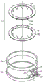
Fig. 4 is an exploded perspective view of a magnetism collecting unit according to an embodiment.
Fig. 5 is an exploded perspective view showing a yoke and a magnetic flux collecting ring of the torque detection device.
Fig. 6 is a perspective view of the magnetic shield cover.
Fig. 7A is a cross-sectional view showing an engagement state of an insertion portion of the magnetic shield and an inserted portion of the magnet collecting holder.
Fig. 7B is a sectional view B-B of fig. 7A.
Fig. 8 is a perspective view of a magnetic shield cover in another embodiment.
Fig. 9 is a cross-sectional view showing an engagement state of an insertion portion of a magnetic shield cover and an inserted portion of a magnetic flux collecting holder according to another embodiment.
Detailed Description
A first embodiment in which the torque detection device of the present invention is embodied will be described below with reference to fig. 1 to 7A and 7B.
As shown in fig. 1, the torque detection device includes a torsion bar 13 that connects an input shaft 11 and an output shaft 12 (see fig. 2), a permanent magnet 15 connected to the input shaft 11, a yoke 14 connected to the output shaft 12, and a cylindrical magnetic flux collecting unit 18 disposed so as to cover the periphery of the yoke 14.
As shown in fig. 2, the torsion bar 13 is formed to have a smaller diameter than the input shaft 11 and the output shaft 12, and is coaxially connected to the input shaft 11 and the output shaft 12. The torsion bar 13 is integrally connected at both ends thereof to the input shaft 11 and the output shaft 12 by pins 11a and 12 a. As shown in fig. 2, the permanent magnet 15 coupled to the input shaft 11 is formed in a cylindrical shape, for example, with 24 poles (N, S poles, 12 poles) magnetized at equal intervals in the circumferential direction, and is fixed coaxially with the input shaft 11. Further, the number of poles is not limited to the above number.
As shown in fig. 2, a cylindrical yoke 14 is coaxially fixed to the output shaft 12. The yoke 14 is disposed so as to surround the permanent magnet 15 with an appropriate gap provided in the radial direction.
As shown in fig. 2, the yoke 14 includes two yokes 14A and 14B (soft magnetic bodies). The yokes 14A and 14B are molded into a cylindrical shape by a synthetic resin body 17 in a state in which 12 isosceles triangular claws 16a extending in one direction perpendicular to the plate surface are provided around a plate-shaped ring 16 at equal intervals, and the claws 16a are opposed to each other at appropriate intervals in the circumferential direction. As shown in fig. 1, the surfaces of the yokes 14A and 14B facing the permanent magnet 15 are exposed from the synthetic resin body 17.
In the neutral state where no torque is applied to the input shaft 11, the yokes 14A and 14B are arranged such that the tips of the claws 16a point at the boundary between the N pole and the S pole of the permanent magnet 15.
As shown in fig. 1, the magnetism collecting unit 18 includes the following components: two magnetism collecting rings 19A, 19B magnetically coupled to the yokes 14A, 14B, respectively, for guiding magnetic fluxes from the yokes 14A, 14B, respectively; a first bracket 20A and a second bracket 20B that hold the respective magnetism collecting rings, respectively; and a magnetic shield 40 that covers the outer sides of the two magnetism collecting rings 19A, 19B in the circumferential direction. In the present embodiment, the first holder 20A and the second holder 20B constitute a magnetism collecting holder. That is, the magnetism collecting holder is configured by aligning and assembling the first holder 20A and the second holder 20B, which have similar shapes when viewed from the axial direction, in the axial direction. The magnetic collecting holder according to the present embodiment can also be regarded as a holder obtained by dividing a conventional integrated magnetic collecting holder into two parts in the axial direction.
As shown in fig. 4, the first bracket 20A is made of synthetic resin, and has an annular ring portion 21 and a circuit cover portion 22 in the form of a covered box integrally connected to the outer peripheral surface of the ring portion 21 and protruding radially outward. A magnetism collecting ring 19A is held on the inner peripheral surface of the ring portion 21, and the magnetism collecting ring 19A is disposed to face the outer peripheral surface of the yoke 14 as shown in fig. 2. The magnetism collecting ring 19A is made of a soft magnetic body. That is, the opposing surfaces of the yokes 14A and 14B and the magnetism collecting ring 19A are exposed and disposed to face each other. The axial direction of the first bracket 20A is the direction of the center axis of the ring portion 21.
As shown in fig. 1 and 4, a positioning protrusion 21a and a plurality of flange pieces 21b that protrude radially outward are provided on the end periphery of the ring 21 on the opposite side to the second bracket side.
As shown in fig. 4, the second holder 20B is made of synthetic resin, and has an annular ring portion 23 and a rectangular plate-shaped substrate installation portion 24 integrally connected to the outer peripheral surface of the ring portion 23 and protruding radially outward. The ring portion 23 has an inner peripheral surface and an outer peripheral surface having the same diameter as the inner peripheral surface and the outer peripheral surface of the ring portion 21 of the first bracket 20A, respectively. The ring portion 23 holds a magnetism collecting ring 19B on its inner peripheral surface, and as shown in fig. 2, the magnetism collecting ring 19B is disposed to face the outer peripheral surface of the yoke 14. The magnetism collecting ring 19B is made of a soft magnetic body. That is, the opposing surfaces of the yokes 14A and 14B and the magnetism collecting ring 19B are exposed and disposed to face each other. The axial direction of the second holder 20B is the direction of the central axis of the ring portion 23.
As shown in fig. 4, the second bracket 20B has a plurality of engaging projecting pieces 25 projecting toward the first bracket 20A on the outer peripheral surface of the ring portion 23. The engaging projecting pieces 25 are fitted into a plurality of fitting grooves 26 recessed in the inner peripheral surface of the ring portion 21 of the first bracket 20A, and engaging claws 25a at the distal end portions thereof are engaged with the axial end surfaces of the ring portion 21 of the first bracket 20A. In this way, the second bracket 20B is disposed coaxially with the first bracket 20A by engaging the engaging projection 25 with the ring portion 21 of the first bracket 20A.
As shown in fig. 1 and 4, a positioning protrusion 23a and a plurality of flange pieces 23b protruding radially outward are provided on the end periphery of the ring 23 on the opposite side to the first bracket side in the axial end portion.
As shown in fig. 5, the two magnetism collecting rings 19A and 19B have flat plate-like protrusions 27 arranged in parallel to each other and closer to each other than other portions, and one or a plurality of hall ICs 31 are inserted into gaps of the adjacent protrusions 27. The hall IC 31 is an example of a magnetic sensor. The magnetic sensor is not limited to the hall IC 31, and may be another element such as a hall element, a magnetoresistive effect element, or a magnetic impedance element.
As shown in fig. 4, the hall IC 31 is fixed to the inner surface of the substrate installation portion 24 together with a circuit substrate 32 (electronic circuit component) on which an electronic circuit connected to the hall IC 31 is formed. The hall IC 31 is connected to a circuit on the circuit board 32 via a plurality of lead wires 33, and the circuit board 32 is connected to an external control device, not shown, via wires 34.
The circuit cover portion 22 is superposed on the substrate installation portion 24, and as shown in fig. 2, a circuit housing chamber 22a is formed between the circuit cover portion 22 and the substrate installation portion 24, and the hall IC 31, the circuit board 32, the lead wire 33, and the like are housed in the circuit housing chamber 22 a.
As shown in fig. 1 and 4, a hooking projection piece 35 projecting toward the circuit cover portion 22 is provided on a side surface of the substrate installation portion 24, and an engagement claw 36 provided at a distal end portion of the hooking projection piece 35 is engaged with an edge portion of the top cover wall 22b of the circuit cover portion 22, thereby keeping the circuit cover portion 22 and the substrate installation portion 24 from overlapping each other.
As shown in fig. 1 and 4, a pair of flanges 28 are formed so as to sandwich both side surfaces of the base end of the substrate installation portion 24, and as shown in fig. 1 and 3, the base end of the circuit cover portion 22 is fitted into a gap formed between the pair of flanges 28. Guide grooves 29 extend from the opposite end surfaces of the flanges 28 in a direction in which the circuit cover portion 22 overlaps the substrate installation portion 24. Partition walls 30 provided in a plate shape in the circuit cover portion 22 are fitted in the guide grooves 29. When the circuit cover portion 22 is overlapped with the substrate installation portion 24, the partition wall 30 is fitted into the guide groove 29, and the overlapping of the first bracket 20A and the second bracket 20B is guided. The flange 28 has a mounting hole 28a formed therethrough for mounting to a housing, not shown, of an electric power steering apparatus or the like.
As shown in fig. 1, 4, and 6, a magnetic shield 40 is fitted to an outer peripheral surface of the ring portion 21 of the first bracket 20A and an outer peripheral surface of the ring portion 23 of the second bracket 20B. The magnetic shield 40 is made of metal, and is formed by bending a steel metal plate into a C-shaped cross section, for example, and approximately half of the axial direction thereof is fitted into the first bracket 20A and the second bracket 20B, respectively, thereby shielding the magnetic force in the radial direction of the input shaft 11 and the output shaft 12.
The axial length of the magnetic shield 40 is slightly longer than the total axial length of the ring portion 21 of the first bracket 20A and the ring portion 23 of the second bracket 20B. In a state where the engagement claws 25a of the engagement projecting pieces 25 are engaged with the axial end surface of the ring portion 21 of the first bracket 20A, both axial end portions of the magnetic shield 40 are brought into contact with the flange pieces 21b of the ring portion 21 and the flange pieces 23b of the ring portion 23.
The magnetic shield 40 is configured such that both circumferential end portions 40a are formed in a flat plate shape, and positioning recesses 42 are provided at both axial end positions in a substantially central portion in the circumferential direction in the C-shaped cross section. By fitting the protrusion 21a of the ring portion 21 and the protrusion 23a of the ring portion 23 in this recess 42, positioning of the magnetic shield 40 in the circumferential direction with respect to the first bracket 20A and the second bracket 20B is completed. The end portion 40a corresponds to an insertion portion.
As shown in fig. 4, in the first bracket 20A, an engagement groove 50 is formed at a portion corresponding to each end portion 40A of the magnetic shield 40, that is, at a portion close to the hall IC 31 side. Each of the engagement grooves 50 of the first holder 20A is open on the side away from the hall IC 31 in the circumferential direction of the ring portion 21, and is open on the side of the second holder 20B. Each engagement groove 50 of the first bracket 20A is closed on the hall IC 31 side of the engagement groove 50 and on the side away from the second bracket 20B in the circumferential direction of the ring portion 21.
As shown in fig. 7A, in the engagement groove 50, on the one hand, the inner surface 54 on the side opposite to the axial center side in the radial direction of the ring portion 21 has a flat surface so as to be along the flat plate-shaped end portion 40a, and on the other hand, the inner surface 52 on the axial center side in the radial direction of the ring portion 21 has a wedge surface 52a so as to become shorter in separation distance from the inner surface 54 facing thereto as it goes toward the opening portion 56 on the second holder 20B side.
In the opening 56, a surface of the wedge surface 52a on the opening 56 side extending from the narrowest portion 52c toward the second bracket 20B serves as a guide surface 52B. The distance between the wedge surface 52a and the inner surface 54 is shortest at the narrowest portion 52 c. The distance between the guide surface 52B and the inner surface 54 becomes longer as it goes toward the second bracket 20B side.
As shown in fig. 4, in the second holder 20B, an engagement groove 51 is formed at a portion corresponding to each end portion 40a of the magnetic shield 40, that is, at a portion close to the hall IC 31 side. Each of the engagement grooves 51 of the second bracket 20B is open on the side away from the hall IC 31 in the circumferential direction of the ring portion 23, and is open on the side of the first bracket 20A. Each of the engagement grooves 51 of the second holder 20B is closed on the hall IC 31 side of the engagement groove 51 and on the side away from the first holder 20A in the circumferential direction of the ring portion 23.
As shown in fig. 7A, in the engagement groove 51, on the one hand, the inner surface 55 on the side opposite to the axial center side in the radial direction of the ring portion 23 has a flat surface so as to be along the flat plate-shaped end portion 40A, and on the other hand, the inner surface 53 on the axial center side in the radial direction of the ring portion 23 has a wedge surface 53a so as to become shorter as it goes toward the opening portion 58 on the first bracket 20A side with respect to the opposing inner surface 55. In the opening portion 58, a surface of the wedge surface 53a that extends from the narrowest portion 53c toward the first bracket 20A in the opening portion 58 is a guide surface 53 b. The distance between the wedge surface 53a and the inner surface 55 is shortest at the narrowest portion 53 c. The distance between the guide surface 53b and the inner surface 55 becomes longer as it goes toward the first bracket 20A side. The engagement grooves 50, 51 correspond to the inserted portions.
As shown in fig. 4 and 6, the end portions 40a of the magnetic shield 40 in the circumferential direction are inserted into the engaging grooves 50 and 51, respectively. As shown in fig. 7A, each end portion 40a is provided with: an engaging member 41a that abuts a wedge surface 52a of the engaging groove 50 on the axial center side in the radial direction of the ring portion 21; and an engaging member 41b that abuts against a wedge surface 53a of the engaging groove 51 on the axial center side in the radial direction of the ring portion 23.
In the present embodiment, the engaging members 41a and 41b have elasticity, and are formed so that free ends thereof face each other and protrude from the surface of the magnetic shield 40. In other words, the engaging members 41a and 41b are formed to be poked inward in the radial direction of the magnetic shield 40 with respect to the end portion 40a, and are elastically locked to the wedge surfaces 52a and 53 a.
In the present embodiment, in fig. 7A, the insertion direction of the engagement member 41a into the engagement groove 50 is a depth direction (upward direction in fig. 7A) in which the opening 56 serves as an insertion port. When the end portion 40a is inserted into the engagement groove 50, the outer surface of the end portion 40a is brought into sliding contact with the inner surface 54 of the engagement groove 50. Thus, the tip of the engaging member 41a is guided by the guide surface 52b of the opening 56. Then, when the end portion 40a (the magnetic shield 40) is moved in the axial direction of the end portion 40a until the end surface on the side opposite to the second holder 20B comes into contact with the groove bottom of the engaging groove 50, the engaging member 41a is deflected toward the inner surface 54 against its own elastic force when the tip of the engaging member 41a moves to the narrowest portion 52 c. When the tip of the engaging member 41a passes through the narrowest portion 52c, the tip of the engaging member 41a is elastically locked to the wedge surface 52a (see fig. 7A and 7B). As the wedge surface 52a moves toward the opening 56 side (in the opposite direction to the insertion direction), the distance between the wedge surface 52a and the inner surface 54 decreases, and movement of the engaging member 41a, that is, the magnetic shield cover 40 in the opposite direction to the insertion direction is restricted.
In fig. 7A, the insertion direction of the engagement member 41b into the engagement groove 51 is a depth direction (downward direction in fig. 7A) in which the opening 58 is an insertion port. When the end portion 40a is inserted into the engagement groove 51, the outer surface of the end portion 40a is brought into sliding contact with the inner surface 55 of the engagement groove 51. Thus, the tip of the engaging member 41b is guided by the guide surface 53b of the opening 58. When the end portion 40A (the magnetic shield 40) is moved in the axial direction of the end portion 40A until the end surface on the opposite side to the first bracket 20A side abuts against the groove bottom of the engaging groove 51, the engaging member 41b is deflected toward the inner surface 55 against its own elastic force when the tip of the engaging member 41b is moved to the narrowest portion 53 c. When the tip of the engaging member 41B passes through the narrowest portion 53c, the tip of the engaging member 41B is elastically locked to the wedge surface 53a (see fig. 7A and 7B). The distance between the wedge surface 53a and the inner surface 55 becomes shorter as the wedge surface 53a moves toward the opening 58 side (in the opposite direction to the insertion direction), and therefore, the movement of the engaging member 41b, that is, the magnetic shield cover 40 in the opposite direction to the insertion direction is restricted.
The operation of the torque detection device configured as described above will be described. The principle of torque detection by the torque detection device is well known, and therefore, the description will be briefly made. When the input shaft 11 shown in fig. 2 is operated to generate an angular difference between the permanent magnet 15 and the yokes 14A and 14B connected to the torsion bar 13, the magnetic flux of the permanent magnet 15 is transmitted from the yokes 14A and 14B to the magnetism collecting rings 19A and 19B. The hall ICs 31 held by the protruding portions 27 of the magnetism collecting rings 19A and 19B detect the steering torque by conducting magnetic flux proportional to the torsion angle of the torsion bar 13.
In the present embodiment, even if the end portion 40a of the magnetic shield 40 attempts to move in the direction opposite to the insertion direction, the engaging members 41a, 41b are always engaged (locked) with the inner surfaces of the engaging grooves 50, 51, thereby restricting the movement of the end portion 40a in the direction opposite to the insertion direction. As a result, the magnetic shield 40 can be fixed to the first bracket 20A and the second bracket 20B without requiring a member for fixing the magnetic shield 40, and the magnetic shield 40 and the first bracket 20A and the second bracket 20B are not loosened.
The present embodiment has the following features.
(1) The torque detecting device of the present embodiment has engaging grooves 50, 51 (inserted portions) on the outer peripheral surfaces of the first holder 20A and the second holder 20B (magnetic flux collecting holder), and the engaging grooves 50, 51 allow the magnetic shield 40 to be inserted when the magnetic shield 40 is fitted. Further, the end portion 40a (insertion portion) of the magnetic shield 40 inserted into the engagement groove 50, 51 (insertion portion) is provided with the engagement member 41a, 41b, and the engagement member 41a, 41b is always engaged with the inner surface of the engagement groove 50, 51 (insertion portion) in a state inserted into the engagement groove 50, 51 (insertion portion), and restricts the movement of the end portion 40a (insertion portion) in the direction opposite to the insertion direction. According to the above configuration, even if the end portion 40a (the insertion portion) attempts to move in the direction opposite to the insertion direction, the engaging members 41a and 41b are always engaged with the inner surfaces of the engaging grooves 50 and 51 (the inserted portions), and the movement of the end portion 40a (the insertion portion) in the direction opposite to the insertion direction is restricted. As a result, the magnetic shield can be fixed to the bracket without requiring a member for fixing the magnetic shield, and the magnetic shield does not become loose therebetween.
(2) The magnetic collecting holder of the torque detecting device of the present embodiment includes a first holder 20A and a second holder 20B that have a shape divided into two parts in the axial direction and are assembled to each other. The two brackets, the first bracket 20A and the second bracket 20B, have engagement grooves 50 and 51 (inserted portions). According to the above configuration, even if the magnetism collecting holder is divided into two parts in the axial direction, the engaging grooves 50 and 51 (inserted portions) can be provided in the two divided parts (the first holder 20A and the second holder 20B), and the operational effect (1) can be achieved.
(3) The torque detection device of the present embodiment has both ends 40a positioned in the circumferential direction of the magnetic shield 40 as insertion portions. Even with the above configuration, the operational effect of (1) can be achieved.
(4) In the torque detection device of the present embodiment, the engagement grooves 50 and 51 (the inserted portions) are configured such that the distance between the engagement members 41a and 41b and the inner surface of the restriction end portion 40a (the insertion portion) that moves relative to each other in the direction opposite to the insertion direction and the other inner surface that faces the inner surface become shorter as the distance becomes closer to the direction opposite to the insertion direction. Therefore, the movement of the engaging members 41a and 41b in the direction opposite to the insertion direction can be further restricted.
(5) In the torque detection device of the present embodiment, the engagement members 41a and 41b are formed by poking up the magnetic shield 40. According to the above configuration, even if the end portion 40a (insertion portion) of the magnetic shield 40 attempts to move in the direction opposite to the insertion direction, the engagement members 41a and 41b formed by poking can be engaged with the inner surfaces of the engagement grooves 50 and 51 (insertion portions) at all times, and the movement of the end portion 40a in the direction opposite to the insertion direction can be restricted.
(6) In the torque detection device of the present embodiment, the engagement members 41a and 41b have elasticity, and are elastically locked to the inner surfaces of the engagement grooves 50 and 51 (inserted portions). According to the above configuration, the engaging members 41a and 41b are elastically locked to the inner surfaces of the engaging grooves 50 and 51 (inserted portions), so that even if the end portion 40a (inserted portion) attempts to move in the direction opposite to the insertion direction, the engaging members can be always engaged with the inner surfaces of the engaging grooves 50 and 51 (inserted portions), and the movement of the end portion 40a (inserted portion) in the direction opposite to the insertion direction can be restricted.
Next, a torque detection device according to a second embodiment will be described with reference to fig. 8 and 9. Note that the same configurations as those of the first embodiment will not be described, and different configurations will be described.
In the present embodiment, as shown in fig. 8, the manner of poking up the engaging members of the magnetic shield 40 is different from that of the first embodiment. That is, as shown in fig. 8, each end portion 40a (insertion portion) of the magnetic shield 40 has an engaging member 43 in the circumferential direction of the magnetic shield 40, and the engaging member 43 is formed so as to be inwardly stabbed with its free end facing the central portion side in the circumferential direction of the magnetic shield 40.
On the other hand, as shown in fig. 9, the first holder 20A and the second holder 20B constituting the magnetism collecting holder are respectively provided with an engagement groove 61 as an inserted portion. In the engaging groove 61, a wedge surface 62a is provided on an inner surface 62 on the axial center side facing the engaging member 43, and the distance between the wedge surface 62a and the other inner surface facing each other becomes shorter as the wedge surface 62a approaches the insertion opening, that is, the distance between the inner surfaces facing each other becomes shorter. In the present embodiment, the engaging member 43 also has elasticity. The insertion direction of the present embodiment is the circumferential direction of the magnetic shield 40, and is the direction in which the magnetic shield 40 is fitted from the outside in the radial direction of the first bracket 20A, the second bracket 20B.
In this case, since the distance separating the end portions 40A of the magnetic shield 40 formed in the C-shaped cross section is shorter than the outer diameters of the ring portions 23 and 23 of the first bracket 20A and the second bracket 20B, when the end portions are inserted into the engaging grooves 61, the end portions of the magnetic shield 40 are inserted while being spread apart.
In the present embodiment, even if the end portion 40a of the magnetic shield 40 attempts to move in the direction opposite to the insertion direction, the engaging member 43 is always engaged (locked) with the wedge surface 62a, which is the inner surface of the engaging groove 61, and the movement of the end portion 40a in the direction opposite to the insertion direction is restricted. In the present embodiment, the magnetic shield 40 can be fixed to the first bracket 20A and the second bracket 20B without requiring a member for fixing the magnetic shield 40, and the magnetic shield 40 and the first bracket 20A and the second bracket 20B are not loosened.
The embodiments of the present invention are not limited to the above-described embodiments, and may be modified as described below. In the above embodiment, the engaging member is formed by punching the magnetic shield 40, but the engaging member is not limited to the punching, and may be formed separately from the magnetic shield 40 and fixed to be integrated with the magnetic shield 40. The fastening of the engaging member to the magnetic shield 40 may be performed by welding, caulking, screwing, or the like.
In the above embodiment, the engaging members 41a and 41B are provided and inserted into the engaging groove 50 of the first bracket 20A and the engaging groove 51 of the second bracket 20B, but an engaging groove may be provided in only one of the brackets and inserted into the engaging groove. In this case, a wedge surface and a guide surface may be provided on an inner surface of any one of the engagement grooves, and an engagement member that is always locked to the wedge surface may be provided on the end portion 40 a.
The outer peripheral sides of the first bracket 20A and the second bracket 20B, the outer peripheral sides of the circuit cover portion 22 and the substrate installation portion 24, the flange 28, and the partition wall 30 of the torque detection device according to the above embodiment may be molded.
The insertion portion is provided at the end portion 40a of the magnetic shield 40, but the insertion portion is not limited to the end portion, and may be provided at another portion such as a circumferential center portion of the magnetic shield 40. In the second embodiment, the magnetic flux collecting holder is configured by the first holder 20A and the second holder 20B divided into two in the axial direction, but may be a single magnetic flux collecting holder without being divided into two.
The magnetic shield 40 may be formed in another shape such as a substantially U-shape. In the above embodiment, the wedge surfaces 52a and 53a of the engagement grooves 50 and 51 may be omitted. Instead, the elastic force of the engaging members 41a and 41b may be increased to increase the contact force with which the inner surfaces of the engaging grooves 50 and 51 are locked (contacted).
In the above embodiment, the engagement members 41a, 41b, and 43 are arranged to have their pricking directions set inward in the radial direction of the magnetic shield 40, but they may be arranged to have their pricking directions set outward in the radial direction. In this case, the wedge surfaces formed on the inner surfaces of the engagement grooves 50 and 51 may be formed on the inner surface on the opposite side to the above-described embodiment.
The present application claims priority from Japanese patent application No. 2016-.
Claims (5)
1. A torque detection device is characterized by comprising:
a permanent magnet;
a yoke that is disposed in a magnetic field formed by the permanent magnet and whose position relative to the permanent magnet changes;
a cylindrical magnetism collecting unit having a magnetism collecting holder formed in a cylindrical shape so as to surround the yoke, a magnetism collecting ring attached to an inner peripheral surface of the magnetism collecting holder and collecting magnetic flux of the yoke, and a magnetic shield fitted to an outer peripheral surface of the magnetism collecting holder; and
a magnetic sensor for detecting a magnetic flux of a magnetic circuit formed by the permanent magnet, the yoke, and the magnetism collecting ring,
an inserted portion into which the magnetic shield is inserted when the magnetic shield is fitted is provided on an outer peripheral surface of the magnetism collecting holder,
an engaging member is provided at an insertion portion of the magnetic shield, the insertion portion being a portion to be inserted into the inserted portion, the engaging member being constantly engaged with an inner surface of the inserted portion in a state of being inserted into the inserted portion to restrict movement of the inserted portion in a direction opposite to an insertion direction,
the inserted portion has a first inner surface and a second inner surface that restrict the engaging member and the inserted portion from moving relative to each other in the opposite direction to the insertion direction,
the distance separating the first inner surface from the second inner surface facing the first inner surface is shorter as the direction of insertion is opposite.
2. The torque detection device according to claim 1,
the magnetic collection bracket comprises a first bracket and a second bracket which are aligned and assembled in an axial arrangement,
at least one of the first bracket and the second bracket has the inserted portion.
3. The torque detection device according to claim 1 or 2,
the insertion portions are provided at both circumferential ends of the magnetic shield case.
4. The torque detection device according to claim 1 or 2,
the engaging member is formed to protrude from a surface of the magnetic shield.
5. The torque detection device according to claim 1 or 2,
the engaging member has elasticity and is elastically locked to an inner surface of the inserted portion.
Applications Claiming Priority (2)
| Application Number | Priority Date | Filing Date | Title |
|---|---|---|---|
| JP2016091394A JP6665668B2 (en) | 2016-04-28 | 2016-04-28 | Torque detector |
| JP2016-091394 | 2016-04-28 |
Publications (2)
| Publication Number | Publication Date |
|---|---|
| CN107402090A CN107402090A (en) | 2017-11-28 |
| CN107402090B true CN107402090B (en) | 2021-01-22 |
Family
ID=58638703
Family Applications (1)
| Application Number | Title | Priority Date | Filing Date |
|---|---|---|---|
| CN201710270651.6A Active CN107402090B (en) | 2016-04-28 | 2017-04-24 | Torque detection device |
Country Status (4)
| Country | Link |
|---|---|
| US (1) | US10060808B2 (en) |
| EP (1) | EP3239678B1 (en) |
| JP (1) | JP6665668B2 (en) |
| CN (1) | CN107402090B (en) |
Families Citing this family (11)
| Publication number | Priority date | Publication date | Assignee | Title |
|---|---|---|---|---|
| JP6294261B2 (en) * | 2015-04-27 | 2018-03-14 | 株式会社ホンダロック | Torque detection device |
| JP6683055B2 (en) * | 2016-07-27 | 2020-04-15 | 株式会社ジェイテクト | Torque detection device and electric power steering device |
| KR101992277B1 (en) * | 2017-11-30 | 2019-06-24 | 엘에스오토모티브테크놀로지스 주식회사 | Torque Sensor |
| JP7115113B2 (en) * | 2018-07-27 | 2022-08-09 | 株式会社ジェイテクト | sensor device |
| JP7124566B2 (en) * | 2018-08-29 | 2022-08-24 | 株式会社ジェイテクト | sensor device |
| DE102018131712A1 (en) | 2018-12-11 | 2020-06-18 | Thyssenkrupp Ag | Magnetic shielding of a torque sensor for an electromechanical power steering system of a motor vehicle |
| KR102520962B1 (en) * | 2019-02-15 | 2023-04-12 | 현대모비스 주식회사 | Torque sensor module for steering device |
| DE102019105234A1 (en) | 2019-03-01 | 2020-09-03 | Thyssenkrupp Ag | Torque sensor unit with a magnetic shield |
| JP7286090B2 (en) | 2019-08-21 | 2023-06-05 | 多摩川精機株式会社 | Fixing structure of hall IC substrate for torque sensor |
| DE102020117041A1 (en) * | 2020-06-29 | 2021-12-30 | Valeo Schalter Und Sensoren Gmbh | Sensor device for detecting a rotation of a shaft about an axis of rotation |
| KR102624316B1 (en) * | 2021-12-07 | 2024-01-15 | 주식회사 비엠씨 | Brushless dc motor |
Citations (5)
| Publication number | Priority date | Publication date | Assignee | Title |
|---|---|---|---|---|
| CN101017115A (en) * | 2006-02-07 | 2007-08-15 | 株式会社捷太格特 | Torque detecting apparatus and manufacturing method of same |
| CN101646931A (en) * | 2007-03-29 | 2010-02-10 | 株式会社捷太格特 | Torque detecting device |
| JP2014029304A (en) * | 2012-07-31 | 2014-02-13 | Jtekt Corp | Torque detecting device and steering device including the same |
| CN103900748A (en) * | 2012-12-25 | 2014-07-02 | 株式会社捷太格特 | Torque Detector and Steering System including the Torque Detector |
| CN104554427A (en) * | 2013-08-02 | 2015-04-29 | 株式会社捷太格特 | Torque detecting device and electric power steering system |
Family Cites Families (4)
| Publication number | Priority date | Publication date | Assignee | Title |
|---|---|---|---|---|
| EP2133677B1 (en) * | 2007-03-29 | 2013-06-19 | JTEKT Corporation | Torque detecting device |
| JP5221679B2 (en) * | 2008-06-26 | 2013-06-26 | テソン エレクトリック シーオー エルティディ | Non-contact torque sensor for steering device |
| JP5994263B2 (en) | 2012-02-01 | 2016-09-21 | 株式会社ジェイテクト | Torque detection device and manufacturing method thereof |
| WO2016032236A1 (en) * | 2014-08-28 | 2016-03-03 | 대성전기공업 주식회사 | Torque sensor device |
-
2016
- 2016-04-28 JP JP2016091394A patent/JP6665668B2/en active Active
-
2017
- 2017-04-24 CN CN201710270651.6A patent/CN107402090B/en active Active
- 2017-04-25 EP EP17168043.2A patent/EP3239678B1/en active Active
- 2017-04-26 US US15/497,559 patent/US10060808B2/en active Active
Patent Citations (5)
| Publication number | Priority date | Publication date | Assignee | Title |
|---|---|---|---|---|
| CN101017115A (en) * | 2006-02-07 | 2007-08-15 | 株式会社捷太格特 | Torque detecting apparatus and manufacturing method of same |
| CN101646931A (en) * | 2007-03-29 | 2010-02-10 | 株式会社捷太格特 | Torque detecting device |
| JP2014029304A (en) * | 2012-07-31 | 2014-02-13 | Jtekt Corp | Torque detecting device and steering device including the same |
| CN103900748A (en) * | 2012-12-25 | 2014-07-02 | 株式会社捷太格特 | Torque Detector and Steering System including the Torque Detector |
| CN104554427A (en) * | 2013-08-02 | 2015-04-29 | 株式会社捷太格特 | Torque detecting device and electric power steering system |
Also Published As
| Publication number | Publication date |
|---|---|
| CN107402090A (en) | 2017-11-28 |
| EP3239678B1 (en) | 2019-01-23 |
| US10060808B2 (en) | 2018-08-28 |
| JP6665668B2 (en) | 2020-03-13 |
| JP2017198608A (en) | 2017-11-02 |
| US20170315004A1 (en) | 2017-11-02 |
| EP3239678A1 (en) | 2017-11-01 |
Similar Documents
| Publication | Publication Date | Title |
|---|---|---|
| CN107402090B (en) | Torque detection device | |
| KR101738781B1 (en) | Magnetic detection device and torque sensor including the same | |
| JP5222542B2 (en) | Current sensor | |
| JP5403792B2 (en) | Current detector assembly structure | |
| US7852067B2 (en) | Shielded position sensor for translationally moving parts | |
| JP2017207402A (en) | Sensor unit and sensor device | |
| KR102363168B1 (en) | Apparatus for sensing | |
| JP7270395B2 (en) | Method for manufacturing magnet assembly, encoder and motor with encoder | |
| EP3816599A1 (en) | Magnetic detection module, detection device, case assembly, and production method for magnetic detection module | |
| CN111556955B (en) | Sensing device | |
| JP5225884B2 (en) | Assembling structure and assembling method of current detection device | |
| CN110779641B (en) | sensor device | |
| US10712215B2 (en) | Detection device and torque sensor | |
| US20180202836A1 (en) | Position sensor | |
| JP6088345B2 (en) | connector | |
| CN109586515B (en) | Motor and sensor mounting structure | |
| JP2018036206A (en) | Sensor device | |
| JP2018191452A (en) | Electrical connection box | |
| KR102534522B1 (en) | Assembly for sensing and apparatus for steering | |
| SA520411348B1 (en) | Cable Clamping Apparatus | |
| JP5700745B2 (en) | Current detector assembly structure | |
| JP7250535B2 (en) | Encoders and motors with encoders | |
| JP7250534B2 (en) | Encoders and motors with encoders | |
| CN111486874B (en) | Method for manufacturing encoder, and motor with encoder | |
| JP2020128898A (en) | Sensor device |
Legal Events
| Date | Code | Title | Description |
|---|---|---|---|
| PB01 | Publication | ||
| PB01 | Publication | ||
| SE01 | Entry into force of request for substantive examination | ||
| SE01 | Entry into force of request for substantive examination | ||
| GR01 | Patent grant | ||
| GR01 | Patent grant |