CN107263399B - Tension adjusting bolt - Google Patents
Tension adjusting bolt Download PDFInfo
- Publication number
- CN107263399B CN107263399B CN201710546726.9A CN201710546726A CN107263399B CN 107263399 B CN107263399 B CN 107263399B CN 201710546726 A CN201710546726 A CN 201710546726A CN 107263399 B CN107263399 B CN 107263399B
- Authority
- CN
- China
- Prior art keywords
- bolt
- adjusting
- groove
- key
- lock
- Prior art date
- Legal status (The legal status is an assumption and is not a legal conclusion. Google has not performed a legal analysis and makes no representation as to the accuracy of the status listed.)
- Active
Links
Images

Classifications
-
- B—PERFORMING OPERATIONS; TRANSPORTING
- B25—HAND TOOLS; PORTABLE POWER-DRIVEN TOOLS; MANIPULATORS
- B25B—TOOLS OR BENCH DEVICES NOT OTHERWISE PROVIDED FOR, FOR FASTENING, CONNECTING, DISENGAGING OR HOLDING
- B25B33/00—Hand tools not covered by any other group in this subclass
Abstract
The invention discloses a tension adjusting bolt which comprises an upper bolt and a lower bolt, wherein the upper part of the upper bolt is provided with a connecting thread, and the lower part of the upper bolt is provided with a convex positioning key; the lower part of the lower bolt is provided with connecting threads, the upper part of the lower bolt is provided with adjusting grooves with equal intervals along the axial direction, and a positioning key of the upper bolt can be adjusted at any position in the adjusting grooves; the adjusting groove is radially arranged at the upper part of the lower bolt; the upper part of the lower bolt is arranged in a hollow tubular shape; the adjusting groove that sets up between two bolts about utilizing, through the interval between the adjusting bolt connection and the height of adjusting nut and bolt, reach the high accuracy pulling force of bolt and adjust, the setting of ring lock can guarantee that the bolt prevents that the navigation key of bolt from droing behind the adjusting position, leads to the occurence of failure.
Description
Technical Field
The invention designs a bolt, and particularly relates to a tension adjusting bolt.
Background
In the field of mechanical devices, it is often necessary to adjust the spacing between two components on the device. Special spacing adjusting devices are often adopted for some precision equipment, and the special devices are usually complex in structure and high in cost; for equipment with not high requirements on adjustment accuracy, manual adjustment is usually adopted by experience, the adjustment error is usually large, and the technical requirements on workers are high.
Disclosure of Invention
The invention provides a tension adjusting bolt, which solves the problem that the distance between two parts of mechanical equipment cannot be accurately adjusted at low cost in the prior art.
The tension adjusting bolt comprises an upper bolt and a lower bolt, wherein the upper part of the upper bolt is provided with a connecting thread, and the lower part of the upper bolt is provided with a convex positioning key; the lower part of the lower bolt is provided with connecting threads, the upper part of the lower bolt is provided with adjusting grooves with equal intervals along the axial direction, and a positioning key of the upper bolt can be adjusted at any position in the adjusting grooves; the adjusting groove is radially arranged at the upper part of the lower bolt; the upper part of the lower bolt is arranged in a hollow tubular shape.
The adjusting groove comprises a shaft groove which is arranged on the side wall of the tubular end of the lower bolt and is arranged along the axial direction, and a plurality of key grooves which are annularly arranged are alternately arranged on the two sides of the shaft groove from top to bottom.
And a locking groove is formed in the side, close to the shaft groove, of the key groove.
The locking groove is in an oval shape.
The bottom of the shaft groove is provided with a ring lock which can move up and down along the shaft groove and is sleeved on the lower bolt.
The ring lock is provided with a locking key which is arranged in the shaft groove.
The lock key is arranged in an oval shape and comprises an oval lock body with two hollowed ends and a semicircular lock head embedded in the hollowed ends of the oval lock body; the semicircular lock heads are supported by springs and partially pop out of the oval lock body.
The height of the oval lock body is smaller than the height of the key groove and smaller than the whole height of the lock key.
The diameter of the upper bolt is smaller than that of the inner ring of the lower bolt.
Compared with the prior art, the beneficial effect who has is: the adjusting groove that sets up between two bolts about utilizing, through the interval between the adjusting bolt connection and the height of adjusting nut and bolt, reach the high accuracy pulling force of bolt and adjust, the setting of ring lock can guarantee that the bolt prevents that the navigation key of bolt from droing behind the adjusting position, leads to the occurence of failure.
Drawings
FIG. 1 is a schematic view of the construction of a tension adjusting bolt according to the present invention;
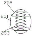
fig. 2 is a cross-sectional view of the catch of the present invention.
Detailed Description
In order to more clearly illustrate the embodiments of the present invention or the technical solutions in the prior art, the drawings used in the description of the embodiments or the prior art will be briefly described below, and it is obvious that the drawings in the following description are only some embodiments of the present invention, and for those skilled in the art, other drawings can be obtained according to these drawings without creative efforts.
The drawing shows an embodiment of the tension adjusting bolt of the invention, which comprises an upper bolt 1 and a lower bolt 2, wherein the upper part of the upper bolt is provided with a connecting thread, and the lower part of the upper bolt is provided with a convex positioning key 11; the lower part of the lower bolt is provided with connecting threads, the upper part of the lower bolt is provided with adjusting grooves with equal intervals along the axial direction, and a positioning key of the upper bolt can be adjusted at any position in the adjusting grooves; the adjusting grooves are radially arranged on two sides of the upper part of the lower bolt; the upper portion of lower bolt is hollow tubulose setting, and upper bolt lower part can wear to establish in the tubulose downthehole of lower bolt.
Further, the adjusting groove comprises a shaft groove 21 which is arranged on the side wall of the tubular end of the lower bolt and is arranged along the axial direction, and a plurality of key grooves 22 which are annularly arranged are alternately arranged on the two sides of the shaft groove from top to bottom.
Further, the key groove is provided with a locking groove 23 near the shaft groove side.
Further, the locking groove is oval.
Further, a ring lock 24 which can move up and down along the shaft groove and is sleeved on the lower bolt is arranged at the bottom of the shaft groove.
Furthermore, a locking key 25 is arranged on the ring lock, and the locking key is arranged in the shaft groove.
Further, the locking key is arranged in an oval shape and comprises an oval lock body 251 with two hollowed ends and a semicircular lock head 252 embedded in the hollowed ends of the oval lock body; the semicircular lock heads are supported by a spring 253 and partially eject out of the oval lock body.
Furthermore, the height of the oval lock body is smaller than the height of the key groove and smaller than the whole height of the locking key.
Further, the diameter of the upper bolt is smaller than that of the inner ring of the lower bolt.
The above description is only for the purpose of illustrating the preferred embodiments of the present invention and is not to be construed as limiting the invention, and any modifications, equivalents, improvements and the like that fall within the spirit and principle of the present invention are intended to be included therein.
Claims (2)
1. Tension adjusting bolt, its characterized in that: the bolt comprises an upper bolt and a lower bolt, wherein the upper part of the upper bolt is provided with a connecting thread, and the lower part of the upper bolt is provided with a convex positioning key; the lower part of the lower bolt is provided with connecting threads, the upper part of the lower bolt is provided with adjusting grooves with equal intervals along the axial direction, and a positioning key of the upper bolt can be adjusted at any position in the adjusting grooves; the adjusting groove is radially arranged at the upper part of the lower bolt; the upper part of the lower bolt is arranged in a hollow tubular shape; the adjusting groove comprises a shaft groove which is arranged on the side wall of the tubular end of the lower bolt and is arranged along the axial direction, and a plurality of key grooves which are arranged annularly are alternately arranged on the upper side and the lower side of the two sides of the shaft groove; a locking groove is formed in the side, close to the shaft groove, of the key groove; the locking groove is in an oval shape; the bottom of the shaft groove is provided with a ring lock which can move up and down along the shaft groove and is sleeved on the lower bolt; the ring lock is provided with a locking key which is arranged in the shaft groove; the lock key is arranged in an oval shape and comprises an oval lock body with two hollowed ends and a semicircular lock head embedded in the hollowed ends of the oval lock body; the semicircular lock heads are supported by springs and partially pop out of the oval lock body; the height of the oval lock body is smaller than the height of the key groove and smaller than the whole height of the lock key.
2. The tension adjusting bolt as defined in claim 1, wherein: the diameter of the upper bolt is smaller than that of the inner ring of the lower bolt.
Priority Applications (1)
| Application Number | Priority Date | Filing Date | Title |
|---|---|---|---|
| CN201710546726.9A CN107263399B (en) | 2017-07-06 | 2017-07-06 | Tension adjusting bolt |
Applications Claiming Priority (1)
| Application Number | Priority Date | Filing Date | Title |
|---|---|---|---|
| CN201710546726.9A CN107263399B (en) | 2017-07-06 | 2017-07-06 | Tension adjusting bolt |
Publications (2)
| Publication Number | Publication Date |
|---|---|
| CN107263399A CN107263399A (en) | 2017-10-20 |
| CN107263399B true CN107263399B (en) | 2020-01-14 |
Family
ID=60073168
Family Applications (1)
| Application Number | Title | Priority Date | Filing Date |
|---|---|---|---|
| CN201710546726.9A Active CN107263399B (en) | 2017-07-06 | 2017-07-06 | Tension adjusting bolt |
Country Status (1)
| Country | Link |
|---|---|
| CN (1) | CN107263399B (en) |
Families Citing this family (1)
| Publication number | Priority date | Publication date | Assignee | Title |
|---|---|---|---|---|
| CN115434632A (en) * | 2022-09-21 | 2022-12-06 | 盐城市新永佳石油机械制造有限公司 | Oil seal transmission shaft combined transmission assembly for screw drill |
Citations (6)
| Publication number | Priority date | Publication date | Assignee | Title |
|---|---|---|---|---|
| JPH08109914A (en) * | 1994-10-12 | 1996-04-30 | Ishikawajima Harima Heavy Ind Co Ltd | Cooling bolt |
| CN203948414U (en) * | 2014-01-23 | 2014-11-19 | 国家电网公司 | Telescopic universal connecting piece |
| CN204005111U (en) * | 2014-06-23 | 2014-12-10 | 何国煜 | A kind of extending foot that is applied to tripod |
| CN104963923A (en) * | 2015-07-13 | 2015-10-07 | 常州市宏硕电子有限公司 | Rotary air cylinder stroke adjusting screw |
| CN205136301U (en) * | 2015-11-26 | 2016-04-06 | 文登蓝岛建筑工程有限公司 | Variable -length's bolt |
| CN205494992U (en) * | 2016-03-06 | 2016-08-24 | 宿州学院 | Training is with hurdling |
-
2017
- 2017-07-06 CN CN201710546726.9A patent/CN107263399B/en active Active
Patent Citations (6)
| Publication number | Priority date | Publication date | Assignee | Title |
|---|---|---|---|---|
| JPH08109914A (en) * | 1994-10-12 | 1996-04-30 | Ishikawajima Harima Heavy Ind Co Ltd | Cooling bolt |
| CN203948414U (en) * | 2014-01-23 | 2014-11-19 | 国家电网公司 | Telescopic universal connecting piece |
| CN204005111U (en) * | 2014-06-23 | 2014-12-10 | 何国煜 | A kind of extending foot that is applied to tripod |
| CN104963923A (en) * | 2015-07-13 | 2015-10-07 | 常州市宏硕电子有限公司 | Rotary air cylinder stroke adjusting screw |
| CN205136301U (en) * | 2015-11-26 | 2016-04-06 | 文登蓝岛建筑工程有限公司 | Variable -length's bolt |
| CN205494992U (en) * | 2016-03-06 | 2016-08-24 | 宿州学院 | Training is with hurdling |
Also Published As
| Publication number | Publication date |
|---|---|
| CN107263399A (en) | 2017-10-20 |
Similar Documents
| Publication | Publication Date | Title |
|---|---|---|
| CN202273956U (en) | Locking pin column | |
| WO2015120733A8 (en) | Thrust rod ball joint assembly, assembly tool and assembly method thereof | |
| CN107263399B (en) | Tension adjusting bolt | |
| RU2016107799A (en) | ANCHOR BOLT | |
| CN105889284A (en) | Lock bolt for heavy machinery | |
| JP2018194009A5 (en) | ||
| CN106089921A (en) | Guide pre-tensioned type bolt | |
| CN202418130U (en) | Rapid connecting structure for rod member and base | |
| CN107701571A (en) | A kind of non-return type bolt assembly | |
| CN203584997U (en) | Novel connecting structure | |
| CN204067547U (en) | A kind of satellite antenna rotating mechanism | |
| CN205639515U (en) | Positioning nut | |
| CN204267265U (en) | A kind of jump ring | |
| CN204344648U (en) | Landing net connector | |
| US11585367B2 (en) | Installation nut | |
| JP2015159943A5 (en) | ||
| CN102730541B (en) | A disc part lifting device | |
| CN103644185B (en) | Hold curved bolt fastening structure | |
| CN102269206B (en) | Threadless connecting screw | |
| CN206092922U (en) | Screw thread clearance remove device | |
| JP3205313U (en) | Adjustable assembly member for vehicle sunshade | |
| CN204565821U (en) | Grinding head motor | |
| CN204457451U (en) | Bracing or strutting arrangement, mast assembly and rotary drilling rig | |
| CN203853933U (en) | Slide bar | |
| CN204175204U (en) | A kind of horizontal well injection technology pipe column centralizer |
Legal Events
| Date | Code | Title | Description |
|---|---|---|---|
| PB01 | Publication | ||
| PB01 | Publication | ||
| SE01 | Entry into force of request for substantive examination | ||
| SE01 | Entry into force of request for substantive examination | ||
| GR01 | Patent grant | ||
| GR01 | Patent grant |