CN107257990B - Method and device for converting HDR version of picture into SDR version - Google Patents
Method and device for converting HDR version of picture into SDR version Download PDFInfo
- Publication number
- CN107257990B CN107257990B CN201580068390.9A CN201580068390A CN107257990B CN 107257990 B CN107257990 B CN 107257990B CN 201580068390 A CN201580068390 A CN 201580068390A CN 107257990 B CN107257990 B CN 107257990B
- Authority
- CN
- China
- Prior art keywords
- version
- picture
- color
- sdr
- hdr
- Prior art date
- Legal status (The legal status is an assumption and is not a legal conclusion. Google has not performed a legal analysis and makes no representation as to the accuracy of the status listed.)
- Active
Links
- 238000000034 method Methods 0.000 title claims abstract description 42
- 238000013507 mapping Methods 0.000 claims abstract description 50
- 238000006243 chemical reaction Methods 0.000 claims abstract description 12
- 238000004891 communication Methods 0.000 claims description 11
- 230000003287 optical effect Effects 0.000 claims description 6
- 230000015654 memory Effects 0.000 description 15
- 230000008569 process Effects 0.000 description 8
- 230000006870 function Effects 0.000 description 5
- 239000003086 colorant Substances 0.000 description 4
- 238000010586 diagram Methods 0.000 description 4
- 238000012986 modification Methods 0.000 description 3
- 230000004048 modification Effects 0.000 description 3
- 238000012545 processing Methods 0.000 description 3
- 238000003491 array Methods 0.000 description 2
- 230000001413 cellular effect Effects 0.000 description 2
- 230000000670 limiting effect Effects 0.000 description 2
- 229920001690 polydopamine Polymers 0.000 description 2
- 239000004065 semiconductor Substances 0.000 description 2
- 244000025254 Cannabis sativa Species 0.000 description 1
- 230000008859 change Effects 0.000 description 1
- 230000000295 complement effect Effects 0.000 description 1
- 238000004590 computer program Methods 0.000 description 1
- 230000002708 enhancing effect Effects 0.000 description 1
- 230000005764 inhibitory process Effects 0.000 description 1
- 230000003993 interaction Effects 0.000 description 1
- 238000004519 manufacturing process Methods 0.000 description 1
- 229910044991 metal oxide Inorganic materials 0.000 description 1
- 150000004706 metal oxides Chemical class 0.000 description 1
- 239000000203 mixture Substances 0.000 description 1
- 230000000717 retained effect Effects 0.000 description 1
- 238000001228 spectrum Methods 0.000 description 1
Images


Classifications
-
- H—ELECTRICITY
- H04—ELECTRIC COMMUNICATION TECHNIQUE
- H04N—PICTORIAL COMMUNICATION, e.g. TELEVISION
- H04N9/00—Details of colour television systems
- H04N9/64—Circuits for processing colour signals
- H04N9/642—Multi-standard receivers
-
- H—ELECTRICITY
- H04—ELECTRIC COMMUNICATION TECHNIQUE
- H04N—PICTORIAL COMMUNICATION, e.g. TELEVISION
- H04N1/00—Scanning, transmission or reproduction of documents or the like, e.g. facsimile transmission; Details thereof
- H04N1/46—Colour picture communication systems
- H04N1/56—Processing of colour picture signals
- H04N1/60—Colour correction or control
- H04N1/6058—Reduction of colour to a range of reproducible colours, e.g. to ink- reproducible colour gamut
- H04N1/6063—Reduction of colour to a range of reproducible colours, e.g. to ink- reproducible colour gamut dependent on the contents of the image to be reproduced
- H04N1/6066—Reduction of colour to a range of reproducible colours, e.g. to ink- reproducible colour gamut dependent on the contents of the image to be reproduced dependent on the gamut of the image to be reproduced
-
- G06T5/92—
-
- G—PHYSICS
- G06—COMPUTING; CALCULATING OR COUNTING
- G06T—IMAGE DATA PROCESSING OR GENERATION, IN GENERAL
- G06T5/00—Image enhancement or restoration
-
- G—PHYSICS
- G09—EDUCATION; CRYPTOGRAPHY; DISPLAY; ADVERTISING; SEALS
- G09G—ARRANGEMENTS OR CIRCUITS FOR CONTROL OF INDICATING DEVICES USING STATIC MEANS TO PRESENT VARIABLE INFORMATION
- G09G5/00—Control arrangements or circuits for visual indicators common to cathode-ray tube indicators and other visual indicators
- G09G5/003—Details of a display terminal, the details relating to the control arrangement of the display terminal and to the interfaces thereto
- G09G5/005—Adapting incoming signals to the display format of the display terminal
-
- G—PHYSICS
- G09—EDUCATION; CRYPTOGRAPHY; DISPLAY; ADVERTISING; SEALS
- G09G—ARRANGEMENTS OR CIRCUITS FOR CONTROL OF INDICATING DEVICES USING STATIC MEANS TO PRESENT VARIABLE INFORMATION
- G09G5/00—Control arrangements or circuits for visual indicators common to cathode-ray tube indicators and other visual indicators
- G09G5/02—Control arrangements or circuits for visual indicators common to cathode-ray tube indicators and other visual indicators characterised by the way in which colour is displayed
- G09G5/06—Control arrangements or circuits for visual indicators common to cathode-ray tube indicators and other visual indicators characterised by the way in which colour is displayed using colour palettes, e.g. look-up tables
-
- H—ELECTRICITY
- H04—ELECTRIC COMMUNICATION TECHNIQUE
- H04N—PICTORIAL COMMUNICATION, e.g. TELEVISION
- H04N1/00—Scanning, transmission or reproduction of documents or the like, e.g. facsimile transmission; Details thereof
- H04N1/46—Colour picture communication systems
- H04N1/56—Processing of colour picture signals
- H04N1/60—Colour correction or control
- H04N1/6058—Reduction of colour to a range of reproducible colours, e.g. to ink- reproducible colour gamut
-
- H—ELECTRICITY
- H04—ELECTRIC COMMUNICATION TECHNIQUE
- H04N—PICTORIAL COMMUNICATION, e.g. TELEVISION
- H04N11/00—Colour television systems
- H04N11/06—Transmission systems characterised by the manner in which the individual colour picture signal components are combined
- H04N11/20—Conversion of the manner in which the individual colour picture signal components are combined, e.g. conversion of colour television standards
-
- H—ELECTRICITY
- H04—ELECTRIC COMMUNICATION TECHNIQUE
- H04N—PICTORIAL COMMUNICATION, e.g. TELEVISION
- H04N7/00—Television systems
- H04N7/01—Conversion of standards, e.g. involving analogue television standards or digital television standards processed at pixel level
-
- H—ELECTRICITY
- H04—ELECTRIC COMMUNICATION TECHNIQUE
- H04N—PICTORIAL COMMUNICATION, e.g. TELEVISION
- H04N9/00—Details of colour television systems
- H04N9/64—Circuits for processing colour signals
-
- H—ELECTRICITY
- H04—ELECTRIC COMMUNICATION TECHNIQUE
- H04N—PICTORIAL COMMUNICATION, e.g. TELEVISION
- H04N9/00—Details of colour television systems
- H04N9/64—Circuits for processing colour signals
- H04N9/646—Circuits for processing colour signals for image enhancement, e.g. vertical detail restoration, cross-colour elimination, contour correction, chrominance trapping filters
-
- H—ELECTRICITY
- H04—ELECTRIC COMMUNICATION TECHNIQUE
- H04N—PICTORIAL COMMUNICATION, e.g. TELEVISION
- H04N9/00—Details of colour television systems
- H04N9/64—Circuits for processing colour signals
- H04N9/68—Circuits for processing colour signals for controlling the amplitude of colour signals, e.g. automatic chroma control circuits
-
- G—PHYSICS
- G06—COMPUTING; CALCULATING OR COUNTING
- G06T—IMAGE DATA PROCESSING OR GENERATION, IN GENERAL
- G06T2207/00—Indexing scheme for image analysis or image enhancement
- G06T2207/20—Special algorithmic details
- G06T2207/20172—Image enhancement details
- G06T2207/20208—High dynamic range [HDR] image processing
-
- G—PHYSICS
- G09—EDUCATION; CRYPTOGRAPHY; DISPLAY; ADVERTISING; SEALS
- G09G—ARRANGEMENTS OR CIRCUITS FOR CONTROL OF INDICATING DEVICES USING STATIC MEANS TO PRESENT VARIABLE INFORMATION
- G09G2320/00—Control of display operating conditions
- G09G2320/02—Improving the quality of display appearance
- G09G2320/0271—Adjustment of the gradation levels within the range of the gradation scale, e.g. by redistribution or clipping
- G09G2320/0276—Adjustment of the gradation levels within the range of the gradation scale, e.g. by redistribution or clipping for the purpose of adaptation to the characteristics of a display device, i.e. gamma correction
-
- G—PHYSICS
- G09—EDUCATION; CRYPTOGRAPHY; DISPLAY; ADVERTISING; SEALS
- G09G—ARRANGEMENTS OR CIRCUITS FOR CONTROL OF INDICATING DEVICES USING STATIC MEANS TO PRESENT VARIABLE INFORMATION
- G09G2340/00—Aspects of display data processing
- G09G2340/04—Changes in size, position or resolution of an image
- G09G2340/0407—Resolution change, inclusive of the use of different resolutions for different screen areas
- G09G2340/0428—Gradation resolution change
-
- G—PHYSICS
- G09—EDUCATION; CRYPTOGRAPHY; DISPLAY; ADVERTISING; SEALS
- G09G—ARRANGEMENTS OR CIRCUITS FOR CONTROL OF INDICATING DEVICES USING STATIC MEANS TO PRESENT VARIABLE INFORMATION
- G09G2370/00—Aspects of data communication
- G09G2370/04—Exchange of auxiliary data, i.e. other than image data, between monitor and graphics controller
-
- H—ELECTRICITY
- H04—ELECTRIC COMMUNICATION TECHNIQUE
- H04N—PICTORIAL COMMUNICATION, e.g. TELEVISION
- H04N19/00—Methods or arrangements for coding, decoding, compressing or decompressing digital video signals
- H04N19/30—Methods or arrangements for coding, decoding, compressing or decompressing digital video signals using hierarchical techniques, e.g. scalability
Abstract
The present disclosure generally relates to methods and apparatus for converting a High Dynamic Range (HDR) version of a picture to a Standard Dynamic Range (SDR) version of the picture. The method is characterized in that it converts the high dynamic range version into a standard dynamic range version of the picture according to: a first indicator (I1) indicating the presence of a color mapping parameter; a second indicator (I2) indicating whether the device is configured to convert the high dynamic range version into a standard dynamic range version of the picture by taking into account the color mapping parameters; and a third indicator (I3) indicating whether conversion is prohibited without regard to the color mapping parameters.
Description
Technical Field
The present disclosure relates generally to picture/video conversion. In particular, but not exclusively, the technical field of the present disclosure relates to the conversion of pictures whose pixel values belong to a high dynamic range.
Background
This section is intended to introduce the reader to various aspects of art, which may be related to various aspects of the present disclosure that are described and/or claimed below. This discussion is believed to be helpful in providing the reader with background information to facilitate a better understanding of the various aspects of the present disclosure. Accordingly, it should be understood that these statements are to be read in this light, and not as admissions of prior art.
In the following, a picture contains one or more arrays of samples (pixel values) in a particular picture/video format that specifies all information related to the pixel values of the picture (or video) and all information that can be used by a display and/or any other device, for example to visualize and/or decode the picture (or video). A picture comprises at least one component shaped as a first array of samples, typically a luminance (or brightness) component, and possibly at least one other component shaped as at least one other array of samples, typically a color component. Or, equivalently, the same information may also be represented by a set of arrays of color samples, such as a conventional three-color RGB representation.
The pixel value is represented by a vector of n values, where n is the number of components. Each value of the vector is represented by a number of bits that defines the maximum dynamic range of the pixel value.
Standard dynamic range pictures (SDR pictures) are pictures whose luminance values are represented by a limited number of bits (most commonly 8 or 10). This limited representation does not allow small signal variations to be correctly represented, especially in the dark and bright luminance range. In high dynamic range pictures (HDR pictures), the signal representation is extended in order to maintain a high precision of the signal over its entire range. In HDR pictures, pixel values are typically represented in floating-point format (32-bit or 16-bit for each component, i.e. floating-point or half-floating), the most popular format being openEXR half-floating-point format (16-bit per RGB component, i.e. 48-bit per pixel), or in integers with long representations, typically at least 16-bit.
A color gamut is some complete set of colors. The most common use refers to a set of colors that can be accurately represented in a given situation, such as in a given color space or through some output device.
A color volume is defined by a color space and a dynamic range of values represented in the color space.
For example, the color volume is defined by the RGB ITU-R recommendation bt.2020 color space and the values represented in the RGB color space belong to a dynamic range from 0 to 4000 nits (candelas per square meter). Another example of a color volume is defined by the RGB bt.2020 color space, and the values represented in the RGB color space belong to a dynamic range from 0 to 1000 nits.
Color grading a picture (or video) is the process of altering/enhancing the color of the picture (or video). Generally, color grading a picture involves changing the color volume (color space and/or dynamic range) or changing the color gamut associated with the picture. Thus, two different color graded versions of the same picture are versions of the picture whose values are represented in different color volumes (or color gamuts) or versions of the picture with at least one color being altered/enhanced according to different color grades. This may involve user interaction.
For example, in movie production, pictures and videos are photographed using a three-color camera into RGB color values composed of 3 components (red, green, and blue). The RGB color values depend on the tristimulus characteristics (color primaries) of the sensor. A first color graded version of the taken picture is then obtained for theatrical presentation (using a particular theatrical grade). Typically, the values of the first color-graded version of the captured picture are represented according to a standardized YUV format, such as bt.2020, which defines parameter values for ultra high definition television systems (UHDTV).
The colorist then performs control of the color values of the first color-graded version of the captured picture, typically together with the director of photography, by fine-tuning/adjusting some color values in order to instill artistic intent.
A second color graded version of the picture taken is also obtained for a home release presentation (using a home-specific, blu-ray disc/DVD rating). Typically, the values of the second color-graded version of the captured picture are represented according to a standardized YUV format, such as ITU-R recommendation bt.601(rec.601) defining studio coding parameters for standard 4:3 and wide screen 16:9 aspect ratio standard digital television, or ITU-R recommendation bt.709 defining parameter values for high definition television systems (HDTV).
Obtaining such a second color-graded version of the captured picture typically includes stretching a color volume of the first color-graded version of the captured picture (e.g., RGB bt.20201000 nits modified by the colorist) such that the second color-graded version of the captured picture belongs to the second color volume (e.g., RGB bt.7091000 nits). This is an automatic step that uses a default color mapping function (e.g., for mapping rgbt.2020 format to RGB bt.709) that is typically approximated by a three-dimensional look-up table (also referred to as a 3D LUT). It is noted that all the considered YUV formats are characterized by color primary parameters that allow to define any RGB to YUV and YUV to RGB color mapping.
The colorist then performs control of the color values of the second color-graded version of the captured picture, typically together with the director of photography, by fine-tuning/adjusting some color values to instill artistic intent in the home release.
It is known to explicitly signal a default color mapping to the display, such as a YUV to RGB color mapping, so that the display can apply the appropriate default color mapping. Furthermore, when the color mapping uses color mapping parameters calculated from the first and second color-graded versions of the picture, it is known that these color mapping parameters are also signaled to the display, so that the display can apply the appropriate default color mapping with the appropriate color mapping parameters.
Artistic intent cannot be preserved using default color mapping because some colors (as specified by the colorist) in the first or second color-graded version of the picture may not be preserved when the default color mapping is applied to the first color-graded version of the picture.
For example, memory colors such as flesh or skin tones, blue sky or green grass shadows, etc., should be retained when specified by the colorist for a given level.
A typical use case is as follows: one purchased a new movie on UHD HDR WCG blu-ray disc. Furthermore, he is equipped at home with a UHD blu-ray player adapted to decode the HDR version burned on the blu-ray disc. However, when a blu-ray player is connected to a legacy television set without HDR capability (but which may be 4K UHD and or WCG enabled, as a DVB UHD-1 phase 1 compatible CE device). This means that such blu-ray players have to convert an HDR version of a movie to an SDR version, e.g. an HDTV video signal for a conventional television set. This conversion is referred to as "blind" because the blu-ray player converts the HDR version of the movie without knowing the "true" target movie style (e.g., the current blu-ray disc HD rating). In fact, the artistic intent (non-deterministic processing) may diverge according to the creative intent of the artist/colorist/director of photography and the available picture change palette. Thus, the resulting SDR version of the movie does not retain artistic intent.
The present disclosure has been devised in view of the foregoing.
Disclosure of Invention
In view of the foregoing, aspects of the present disclosure relate to creating and maintaining semantic relationships between data objects on a computer system. The following presents a simplified summary of the disclosure in order to provide a basic understanding of some aspects of the disclosure. This summary is not an extensive overview of the disclosure. It is not intended to identify key or critical elements of the disclosure. The following summary merely presents some aspects of the disclosure in a simplified form as a prelude to the more detailed description provided below.
The present disclosure corrects at least one of the shortcomings of the prior art with a method of converting an HDR version of a picture to an SDR version of the picture. The method is characterized in that it converts the HDR version into an SDR version of the picture according to:
-a first indicator, the presence of which indicates a color mapping parameter;
-a second indicator indicating whether the device is configured to convert the HDR version into an SDR version of the picture by taking into account said color mapping parameters; and
-a third indicator indicating whether conversion is prohibited without taking into account the color mapping parameters.
Thus, in general, a UHD WCG HDR blu-ray disc comprising a reference version of the movie (i.e. a UHD HDR WCG version) and color mapping parameters (e.g. parameters for a legacy television set connected to the HDR blu-ray player that allow remapping of the HDR WCG content to SDR rec.709 content that retains creative intent) may further comprise a first indicator indicating the presence of color mapping parameters on the blu-ray disc for converting the HDR version to an SDR version of the movie. The blu-ray player can then transform the HDR version burned on the disc according to its capabilities (indicated by the second indicator) and according to the value of said first indicator, in order to obtain an SDR version of the movie preserving artistic intent. The third indicator ensures that an SDR version of an HDR version of a movie cannot be obtained by methods that do not preserve artistic intent (blind or non-referenced methods).
According to other aspects, the disclosure relates to an apparatus comprising a processor configured to implement the above method, a computer program product comprising program code instructions for performing the steps of the above method when the program is executed on a computer, a processor-readable medium having instructions stored therein for causing a processor to perform at least the steps of the above method, and a non-transitory storage medium.
The particular nature of the disclosure, as well as other objects, advantages, features, and uses of the disclosure, will become apparent from the following description of the embodiments, which is to be read in connection with the accompanying drawings.
Drawings
In the drawings, embodiments of the present disclosure are illustrated. It shows that:
fig. 1 shows a block diagram of the steps of a method of converting an HDR version of a picture into an SDR version of the picture according to an embodiment of the present disclosure;
figure 2 represents an exemplary architecture of a device configured to implement the method described in relation to figure 1;
fig. 3 schematically shows a system for displaying an SDR version of a picture from an HDR version of the picture according to an embodiment of the present disclosure;
figure 4 shows an embodiment of a method; and
fig. 5 shows an embodiment of the method.
Similar or identical elements are denoted by the same reference numerals.
Detailed Description
The present disclosure now will be described more fully hereinafter with reference to the accompanying drawings, in which embodiments of the disclosure are shown. This disclosure may, however, be embodied in many alternate forms and should not be construed as limited to the embodiments set forth herein. Accordingly, while the disclosure is susceptible to various modifications and alternative forms, specific embodiments thereof have been shown by way of example in the drawings and will herein be described in detail. It should be understood, however, that there is no intention to limit the disclosure to the specific forms disclosed, but on the contrary, the disclosure is to cover all modifications, equivalents, and alternatives falling within the spirit and scope of the disclosure as defined by the claims.
The terminology used herein is for the purpose of describing particular embodiments only and is not intended to be limiting of the disclosure. As used herein, the singular forms "a", "an" and "the" are intended to include the plural forms as well, unless the context clearly indicates otherwise. It will be further understood that the terms "comprises," "comprising," "includes" and/or "including," when used in this specification, specify the presence of stated features, integers, steps, operations, elements, and/or components, but do not preclude the presence or addition of one or more other features, integers, steps, operations, elements, components, and/or groups thereof. Further, when an element is referred to as being "responsive" or "connected" to another element, it can be directly responsive or connected to the other element or intervening elements may be present. In contrast, when an element is referred to as being "directly responsive" or "directly connected" to other elements, there are no intervening elements present. As used herein, the term "and/or" includes any and all combinations of one or more of the associated listed items and may be abbreviated as "/".
It will be understood that, although the terms first, second, etc. may be used herein to describe various elements, these elements should not be limited by these terms. These terms are only used to distinguish one element from another. For example, a first element could be termed a second element, and, similarly, a second element could be termed a first element, without departing from the teachings of the present disclosure.
Although some of the figures include arrows on communication paths to illustrate the primary direction of communication, it is to be understood that communication may occur in the opposite direction to the depicted arrows.
Some embodiments are described in terms of block diagrams and operational flow diagrams, where each block represents a circuit element, module, or portion of code, which comprises one or more executable instructions for implementing the specified logical function(s). It should also be noted that, in other implementations, the functions noted in the block may occur out of the order noted. For example, two blocks shown in succession may, in fact, be executed substantially concurrently, or the blocks may sometimes be executed in the reverse order, depending upon the functionality involved.
Reference herein to "one embodiment" or "an embodiment" means that a particular feature, structure, or characteristic described in connection with the embodiment can be included in at least one implementation of the disclosure. The appearances of the phrase "in one embodiment" or "in accordance with an embodiment" in various places in the specification are not necessarily all referring to the same embodiment, nor are separate or alternative embodiments necessarily mutually exclusive of other embodiments.
Reference signs appearing in the claims are provided by way of illustration only and shall have no limiting effect on the scope of the claims.
Although not explicitly described, the present embodiments and variations may be used in any combination or sub-combination.
The present disclosure is described for converting pictures, but extends to conversion of a sequence of pictures (video) in that each picture of the sequence is encoded/decoded sequentially, as described below.
It is well known in the art to obtain color mapping parameters by estimating the color mapping between two color-graded versions of the same picture, i.e. estimating the color mapping function that best maps the color values of a first color-graded version of a picture to the color values of a second color-graded version of said picture. The best mapping can be obtained using the least mean method.
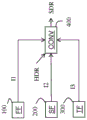
Fig. 1 shows a block diagram of the steps of a method of converting an HDR version of a picture into an SDR version of the picture according to the prior art.
In step 100, module FF obtains a first indicator I1 indicating or identifying the presence of color mapping parameters for converting the HDR version to the SDR version of the picture.
In step 200, the module SF obtains a second indicator I2 indicating whether the device is configured to convert the HDR version into an SDR version of the picture by taking into account said color mapping parameters.
In step 300, the module TF obtains a third indicator I3 indicating whether or not to prohibit a conversion without taking into account said color mapping parameters.
In step 400, the module CONV converts the HDR version of the picture into the SDR version of the picture according to the third, second and third indicators.
According to an embodiment, the first, second and/or third indicator is obtained from a disk or a local memory or a remote memory via a communication network.
According to an embodiment, the second indicator I2 is flag F2 (one bit).
The value of flag F2 is equal to a first value (v (F2) ═ 1) to indicate that the device is configured to convert the HDR version to the SDR version of the picture by taking into account the color mapping parameters.
The value of flag F2 is equal to a second value (v (F2) ═ 0) to indicate that the device is not configured to convert the HDR version to the SDR version of the picture by considering the color mapping parameters.
According to an embodiment, a single indicator SI represents the first and third indicators.
The value of the single indicator SI is equal to a first value (v (SI) ═ 1) to indicate the presence of the color mapping parameter.
The value of the single indicator SI is equal to the second value (v (SI) ═ 0) or the third value (v (SI) ═ 2)), to indicate that there are no color mapping parameters.
According to an embodiment, if the value of the single indicator SI is equal to the second value (v (SI) ═ 0), the device is allowed to convert the HDR version to an SDR version of the picture without considering said color mapping parameters. If the value of the single indicator SI is equal to the third value (v (SI) ═ 2), the device is not allowed to convert the HDR version to the SDR version of the picture without considering the color mapping parameters. If the value of the single indicator SI is equal to the first value (v (SI) ═ 1) to indicate the presence of the color mapping parameters, and the value of the flag F2 is equal to the first value (v (F2) ═ 1), the HDR version is converted into the SDR version of the picture by taking into account said color mapping parameters. If the value of the single indicator SI is equal to the first value (v (SI) ═ 1)) to indicate that the color mapping parameters are present, and the value of the flag F2 is equal to the second value (v (F2) ═ 0), conversion of the HDR version to the SDR version of the picture is prohibited.
According to an embodiment, the first indicator I1 is represented by a first flag F1, and the third indicator I3 is represented by a third flag F3.
The value of the flag F1 is equal to the first value (v (F1) ═ 1) to indicate the presence of the color mapping parameter. The value of the flag F1 is equal to the second value (v (F1) ═ 0) to indicate that there are no color mapping parameters. The value of flag F3 is equal to the first value (v (F3) ═ 1)), then the device is not allowed to convert the HDR version to the SDR version of the picture without considering the color mapping parameters. The value of flag F3 is equal to the second value (v (F3) ═ 0), then the device is allowed to convert the HDR version to the SDR version of the picture without considering the color mapping parameters.
According to an embodiment, when v (F3) ═ 0, the HDR version may be converted to an SDR version of the picture by taking into account the color mapping parameters when v (F1) ═ v (F2) ═ 1, and otherwise without taking into account the color mapping parameters. When v (F3) ═ 1, the HDR version may be converted into an SDR version of the picture by considering the color mapping parameters when v (F1) ═ v (F2) ═ 1, otherwise the HDR version is not converted into an SDR version of the picture.
In fig. 1, modules are functional units, which may or may not be associated with distinguishable physical units. For example, these modules or some of them may be grouped in unique components or circuits or contribute to the functionality of software. Rather, some modules may possibly be composed of separate physical entities. Apparatuses compatible with the present disclosure are implemented using pure hardware, for example using dedicated hardware such as ASIC or FPGA or VLSI, "application specific integrated circuit", "field programmable gate array", "very large scale integrated circuit", respectively, or from a plurality of integrated electronic components embedded in a device or from a mixture of hardware and software components.
Fig. 2 represents an exemplary architecture of a device 20 configured to implement the method described with respect to fig. 1.
The device 20 comprises the following elements linked together by a data and address bus 21:
a processor 22 (or CPU), which is for example a DSP (or digital signal processor);
a ROM (or read only memory) 23;
a RAM (or random access memory) 24;
an I/O interface 25 for receiving data to be transferred from an application;
-a battery 26;
a communication interface 27 and
an optical disc reader 28.
According to a variant, the battery 26 is external to the device. Each of these elements of fig. 2 is well known to those skilled in the art and will not be further disclosed. In each of the mentioned memories, the word "register" used in the description may correspond to an area of small capacity (some bits) or a very large area (e.g. the whole program or a large amount of received or decoded data). The ROM 23 includes at least programs and parameters. The algorithm of the method according to the present disclosure is stored in the ROM 23. When turned on, the CPU 22 uploads programs into the RAM and executes corresponding instructions.
The implementations described herein may be implemented in, for example, a method or process, an apparatus, a software program, a data stream, or a signal. Even if only discussed in the context of a single form of implementation (e.g., only discussed as a method or device), the implementation of the features discussed may be implemented in other forms (e.g., a program). The apparatus may be implemented in, for example, appropriate hardware, software and firmware. The method may be implemented, for example, in a processor, which generally refers to a processing device, including, for example, a blu-ray player, a computer, a microprocessor, an integrated circuit, or a programmable logic device. Processors also include communication devices such as, for example, computers, cellular telephones, portable/personal digital assistants ("PDAs"), and other devices that facilitate the communication of information between end-users.
According to a particular embodiment of the device, the first, second and/or third indicator is obtained from a source. For example, the source belongs to the group comprising:
-local memory (23 or 24), such as video memory or RAM (or random access memory), flash memory, ROM (or read only memory), hard disk;
-a storage interface (25), for example an interface with mass storage, RAM, flash memory, ROM, optical disks or a magnetic support;
a communication interface (27), for example a wired interface (e.g. a bus interface, a wide area network interface, a local area network interface) or a wireless interface (such as an IEEE 802.11 interface or An interface);
-non-transitory storage media such as blu-ray disc; and
a picture capturing circuit (e.g. a sensor such as e.g. a CCD (or charge coupled device) or a CMOS (or complementary metal oxide semiconductor)).
According to various embodiments, the device 20 is configured to implement the method described with respect to fig. 1, belonging to the group comprising:
-a mobile device;
-a communication device;
-a gaming device;
-a tablet (or tablet computer);
-a laptop computer;
-a still picture camera;
-a video camera;
-an encoding chip;
-a still picture server;
-a blu-ray player; and
a video server (e.g. a broadcast server, a video-on-demand server or a web server).
Fig. 3 schematically shows a system for displaying an SDR version of a picture from an HDR version of the picture.
The system comprises a device 20 connected to a conventional television set, for example via an HDMI bus.
According to an embodiment, the optical disc reader 38 of the device 20 obtains the first and/or third indicator from the blu-ray disc and the device also obtains the second indicator, e.g. from the local memory 23.
The processor 22 of the device 20 is then configured to implement the method as described with respect to fig. 1.
According to an embodiment, the non-transitory storage medium is a blu-ray disc, i.e. a disc complying with e.g. the blu-ray specification.
According to an embodiment of the method shown in fig. 4, a single indicator SI is added to the playlist attribute AppInfoPlayList of the blu-ray specification. Such a single indicator may be a syntax element called SDR _ conversion _ type.
According to the variant shown in fig. 5, the first flag F1 is added to the playlist attribute AppInfoPlayList of the blu-ray specification. Such flag F1 may be a syntax element called CRI present flag. A third mark F3 is added to the playlist attribute AppInfoPlayList. Such flag F3 may be a syntax element called SDR _ conversion _ inhibition _ flag.
According to an embodiment, when the device 20 is a blu-ray device, the second flag F2 is added to the player status register of the blu-ray specification. Such a second flag F2 may be, for example, a syntax element called CRI decoder present flag (or CRI capability _flag) or CRI _ encoding _flag).
Implementations of the various processes and features described herein may be embodied in a variety of different equipment or applications. Examples of such equipment include encoders, decoders, post-processors that process output from decoders, pre-processors that provide input to encoders, video decoders, video codecs, web servers, set-top boxes, laptop computers, personal computers, cellular telephones, PDAs, and any other device or other communication device for processing pictures or video. It should be clear that the equipment may be mobile and even mounted in a moving vehicle.
Further, the method may be implemented by instructions being executed by a processor, and such instructions (and/or data values resulting from the implementation) may be stored on a computer-readable medium. The computer-readable storage medium may take the form of a computer-readable program product embodied in one or more computer-readable media and having computer-readable program code embodied thereon that is executable by a computer. A computer-readable storage medium as used herein is considered a non-transitory storage medium having an inherent ability to store information therein and to provide information retrieval therefrom. A computer readable storage medium may be, for example, but not limited to, an electronic, magnetic, optical, electromagnetic, infrared, or semiconductor system, apparatus, or device, or any suitable combination of the foregoing. It is to be understood that while providing more specific examples of computer readable storage media to which the present principles may be applied, the following is merely illustrative and non-exhaustive list that would be readily understood by one of ordinary skill in the art: a portable computer diskette; a hard disk; read Only Memory (ROM); erasable programmable read-only memory (EPROM or flash memory); portable compact disc read only memory (CD-ROM); an optical storage device; a magnetic storage device; or any suitable combination of the foregoing.
The instructions may form an application program tangibly embodied on a processor-readable medium.
The instructions may be in hardware, firmware, software, or a combination thereof, for example. The instructions may reside, for example, in an operating system, a separate application, or a combination of both. Thus, a processor may be characterized as both a device configured to perform a process, for example, and a device that includes a processor-readable medium (such as a storage device) having instructions for performing a process. Further, a processor-readable medium may store data values produced by an implementation in addition to or in place of instructions.
As will be apparent to those of skill in the art, implementations may produce various signals formatted to carry information that may be stored or transmitted, for example. The information may include, for example, instructions for performing a method or data generated by one of the described implementations. For example, the signal may be formatted to carry as data the rules for writing or reading the syntax of the described embodiments or to carry as data the actual syntax values written by the described embodiments. Such signals may be formatted, for example, as electromagnetic waves (e.g., using the radio frequency portion of the spectrum) or as baseband signals. Formatting may include, for example, encoding a data stream and modulating a carrier with the encoded data stream. The information carried by the signal may be, for example, analog information or digital information. As is known, signals may be transmitted over a variety of different wired or wireless links. The signal may be stored on a processor readable medium.
A number of implementations have been described. Nevertheless, it will be understood that various modifications may be made. For example, elements of different implementations may be combined, supplemented, modified, or removed to produce other implementations. Further, one of ordinary skill in the art will appreciate that other structures and processes may be substituted for the disclosed structures and processes and that the resulting implementations will perform at least substantially the same function(s) as the disclosed implementations in a manner that achieves at least substantially the same result(s) as the disclosed implementations. These and other implementations are therefore contemplated by this application.
Claims (8)
1. A method of converting an HDR version of a picture to an SDR version of the picture, the method comprising:
-obtaining first information data indicating the presence of color mapping parameters;
-obtaining second information data indicating whether the device is configured to convert the HDR version into an SDR version of the picture by taking into account said color mapping parameters;
-obtaining third information data indicating whether a conversion of an HDR version of a picture into an SDR version of the picture without taking into account said color mapping parameters is forbidden; and
-converting the HDR version of the picture according to the obtained information data.
2. The method according to claim 1, wherein the first, second and/or third information data is obtained from a disk or a local storage or a remote storage via a communication network.
3. A method according to claim 1, wherein a single information data (SI) represents the first information data and the third information data.
4. A device for converting an HDR version of a picture to an SDR version of the picture, the device comprising a processor configured to:
-obtaining first information data indicating the presence of color mapping parameters;
-obtaining second information data indicating whether the device is configured to convert the HDR version into an SDR version of the picture by taking into account said color mapping parameters;
-obtaining third information data indicating whether a conversion without taking into account said color mapping parameters is prohibited; and
-converting the HDR version of the picture according to the obtained information data.
5. The apparatus of claim 4, further comprising an optical disc reader for obtaining at least one of said information data from a disc.
6. The apparatus of claim 5, wherein the disc is a Blu-ray disc.
7. A system for displaying an SDR version of a picture from an HDR version of the picture, comprising the device of claim 4 for converting the HDR version of the picture into the SDR version of the picture, and an SDR display connected to the device.
8. A processor-readable medium having stored therein instructions for causing a processor to perform at least the method of claim 1.
Applications Claiming Priority (5)
| Application Number | Priority Date | Filing Date | Title |
|---|---|---|---|
| EP14290388.9 | 2014-12-16 | ||
| EP14290388.9A EP3035678A1 (en) | 2014-12-16 | 2014-12-16 | Method and device of converting a high-dynamic-range version of a picture to a standard-dynamic-range version of said picture |
| EP15305023.2 | 2015-01-13 | ||
| EP15305023 | 2015-01-13 | ||
| PCT/EP2015/079083 WO2016096562A1 (en) | 2014-12-16 | 2015-12-09 | Method and device of converting a high-dynamic-range version of a picture to a standard-dynamic-range version of said picture |
Publications (2)
| Publication Number | Publication Date |
|---|---|
| CN107257990A CN107257990A (en) | 2017-10-17 |
| CN107257990B true CN107257990B (en) | 2020-08-18 |
Family
ID=55027698
Family Applications (1)
| Application Number | Title | Priority Date | Filing Date |
|---|---|---|---|
| CN201580068390.9A Active CN107257990B (en) | 2014-12-16 | 2015-12-09 | Method and device for converting HDR version of picture into SDR version |
Country Status (14)
| Country | Link |
|---|---|
| US (2) | US10104354B2 (en) |
| EP (1) | EP3235245B1 (en) |
| JP (1) | JP6663432B2 (en) |
| KR (1) | KR102365440B1 (en) |
| CN (1) | CN107257990B (en) |
| AU (1) | AU2015366617B2 (en) |
| BR (1) | BR112017012845A2 (en) |
| CA (1) | CA2970972A1 (en) |
| MX (1) | MX364481B (en) |
| MY (1) | MY181609A (en) |
| PH (1) | PH12017500885A1 (en) |
| RU (1) | RU2707065C2 (en) |
| TW (1) | TW201633779A (en) |
| WO (1) | WO2016096562A1 (en) |
Families Citing this family (7)
| Publication number | Priority date | Publication date | Assignee | Title |
|---|---|---|---|---|
| KR102308192B1 (en) * | 2017-03-09 | 2021-10-05 | 삼성전자주식회사 | Display apparatus and control method thereof |
| TWI808971B (en) * | 2018-04-30 | 2023-07-21 | 圓剛科技股份有限公司 | Video signal conversion device |
| TWI811217B (en) * | 2018-04-30 | 2023-08-11 | 圓剛科技股份有限公司 | Video signal conversion device |
| TWI808970B (en) | 2018-04-30 | 2023-07-21 | 圓剛科技股份有限公司 | Video signal conversion device |
| EP3588964A1 (en) * | 2018-06-26 | 2020-01-01 | InterDigital VC Holdings, Inc. | Metadata translation in hdr distribution |
| US11743550B2 (en) | 2019-06-28 | 2023-08-29 | Dolby Laboratories Licensing Corporation | Video content type metadata for high dynamic range |
| CN115797151A (en) * | 2021-09-10 | 2023-03-14 | 北京字跳网络技术有限公司 | Color mapping color card generation method and device |
Citations (6)
| Publication number | Priority date | Publication date | Assignee | Title |
|---|---|---|---|---|
| CN103327323A (en) * | 2012-03-14 | 2013-09-25 | 杜比实验室特许公司 | Efficient tone-mapping of high-bit-depth video to low-bit-depth display |
| CN103391435A (en) * | 2013-07-02 | 2013-11-13 | 广东工业大学 | Coding method for high dynamic range (HDR) image compatible with low dynamic range (LDR) and decoding method thereof |
| CN103597812A (en) * | 2011-06-14 | 2014-02-19 | 皇家飞利浦有限公司 | Graphics processing for high dynamic range video |
| CN103843058A (en) * | 2011-09-27 | 2014-06-04 | 皇家飞利浦有限公司 | Apparatus and method for dynamic range transforming of images |
| WO2015072754A1 (en) * | 2013-11-13 | 2015-05-21 | 엘지전자 주식회사 | Broadcast signal transmission method and apparatus for providing hdr broadcast service |
| CN105139368A (en) * | 2015-08-12 | 2015-12-09 | 旗瀚科技股份有限公司 | Hybrid tone mapping method for machine vision |
Family Cites Families (10)
| Publication number | Priority date | Publication date | Assignee | Title |
|---|---|---|---|---|
| US8014445B2 (en) * | 2006-02-24 | 2011-09-06 | Sharp Laboratories Of America, Inc. | Methods and systems for high dynamic range video coding |
| WO2012118961A1 (en) * | 2011-03-02 | 2012-09-07 | Dolby Laboratories Licensing Corporation | Local multiscale tone-mapping operator |
| US8363131B2 (en) * | 2009-01-15 | 2013-01-29 | Aptina Imaging Corporation | Apparatus and method for local contrast enhanced tone mapping |
| CN102388612B (en) * | 2009-03-13 | 2014-10-08 | 杜比实验室特许公司 | Layered compression of high dynamic range, visual dynamic range, and wide color gamut video |
| CN102845071B (en) * | 2010-04-19 | 2015-01-28 | 杜比实验室特许公司 | Quality assessment of high dynamic range, visual dynamic range and wide color gamut image and video |
| CN105787908B (en) * | 2012-08-08 | 2019-05-14 | 杜比实验室特许公司 | Image processing method, device and storage medium for high dynamic range images |
| WO2014128586A1 (en) * | 2013-02-21 | 2014-08-28 | Koninklijke Philips N.V. | Improved hdr image encoding and decoding methods and devices |
| US8866975B1 (en) * | 2013-05-02 | 2014-10-21 | Dolby Laboratories Licensing Corporation | Backwards-compatible delivery of digital cinema content with higher dynamic range and related preprocessing and coding methods |
| US10812801B2 (en) * | 2014-02-25 | 2020-10-20 | Apple Inc. | Adaptive transfer function for video encoding and decoding |
| US10015525B2 (en) * | 2014-10-27 | 2018-07-03 | Dolby Laboratories Licensing Corporation | Content mapping using extended color range |
-
2015
- 2015-12-04 TW TW104140641A patent/TW201633779A/en unknown
- 2015-12-09 BR BR112017012845A patent/BR112017012845A2/en not_active Application Discontinuation
- 2015-12-09 RU RU2017122748A patent/RU2707065C2/en not_active IP Right Cessation
- 2015-12-09 CN CN201580068390.9A patent/CN107257990B/en active Active
- 2015-12-09 CA CA2970972A patent/CA2970972A1/en not_active Abandoned
- 2015-12-09 MX MX2017007918A patent/MX364481B/en active IP Right Grant
- 2015-12-09 EP EP15817101.7A patent/EP3235245B1/en active Active
- 2015-12-09 US US15/537,382 patent/US10104354B2/en active Active
- 2015-12-09 KR KR1020177016733A patent/KR102365440B1/en active IP Right Grant
- 2015-12-09 JP JP2017531870A patent/JP6663432B2/en active Active
- 2015-12-09 WO PCT/EP2015/079083 patent/WO2016096562A1/en active Application Filing
- 2015-12-09 MY MYPI2017701616A patent/MY181609A/en unknown
- 2015-12-09 AU AU2015366617A patent/AU2015366617B2/en active Active
-
2017
- 2017-05-12 PH PH12017500885A patent/PH12017500885A1/en unknown
-
2018
- 2018-09-13 US US16/130,347 patent/US10764549B2/en active Active
Patent Citations (6)
| Publication number | Priority date | Publication date | Assignee | Title |
|---|---|---|---|---|
| CN103597812A (en) * | 2011-06-14 | 2014-02-19 | 皇家飞利浦有限公司 | Graphics processing for high dynamic range video |
| CN103843058A (en) * | 2011-09-27 | 2014-06-04 | 皇家飞利浦有限公司 | Apparatus and method for dynamic range transforming of images |
| CN103327323A (en) * | 2012-03-14 | 2013-09-25 | 杜比实验室特许公司 | Efficient tone-mapping of high-bit-depth video to low-bit-depth display |
| CN103391435A (en) * | 2013-07-02 | 2013-11-13 | 广东工业大学 | Coding method for high dynamic range (HDR) image compatible with low dynamic range (LDR) and decoding method thereof |
| WO2015072754A1 (en) * | 2013-11-13 | 2015-05-21 | 엘지전자 주식회사 | Broadcast signal transmission method and apparatus for providing hdr broadcast service |
| CN105139368A (en) * | 2015-08-12 | 2015-12-09 | 旗瀚科技股份有限公司 | Hybrid tone mapping method for machine vision |
Also Published As
| Publication number | Publication date |
|---|---|
| US10104354B2 (en) | 2018-10-16 |
| CA2970972A1 (en) | 2016-06-23 |
| RU2707065C2 (en) | 2019-11-22 |
| AU2015366617A1 (en) | 2017-07-13 |
| KR102365440B1 (en) | 2022-02-18 |
| MY181609A (en) | 2020-12-29 |
| EP3235245A1 (en) | 2017-10-25 |
| MX2017007918A (en) | 2017-09-05 |
| RU2017122748A3 (en) | 2019-05-22 |
| EP3235245B1 (en) | 2022-09-28 |
| RU2017122748A (en) | 2019-01-23 |
| BR112017012845A2 (en) | 2017-12-26 |
| JP6663432B2 (en) | 2020-03-11 |
| MX364481B (en) | 2019-04-29 |
| TW201633779A (en) | 2016-09-16 |
| KR20170095240A (en) | 2017-08-22 |
| US20170366791A1 (en) | 2017-12-21 |
| US10764549B2 (en) | 2020-09-01 |
| WO2016096562A1 (en) | 2016-06-23 |
| US20190014296A1 (en) | 2019-01-10 |
| CN107257990A (en) | 2017-10-17 |
| PH12017500885A1 (en) | 2017-11-06 |
| JP2018506880A (en) | 2018-03-08 |
| AU2015366617B2 (en) | 2019-11-28 |
Similar Documents
| Publication | Publication Date | Title |
|---|---|---|
| CN107257990B (en) | Method and device for converting HDR version of picture into SDR version | |
| KR102529013B1 (en) | Method and apparatus for encoding and decoding color pictures | |
| US20220210457A1 (en) | Method and device for decoding a color picture | |
| CN109076231B (en) | Method and device for encoding HDR pictures, corresponding decoding method and decoding device | |
| CN114189691A (en) | Method and apparatus for encoding both HDR images and SDR images using color mapping functions | |
| US20170339316A1 (en) | A method and device for estimating a color mapping between two different color-graded versions of a sequence of pictures | |
| EP3035678A1 (en) | Method and device of converting a high-dynamic-range version of a picture to a standard-dynamic-range version of said picture | |
| US9699426B2 (en) | Method and device for estimating a color mapping between two different color-graded versions of a picture | |
| US20170337708A1 (en) | A method and device for estimating a color mapping between two different color-graded versions of a picture | |
| CA2973637A1 (en) | A method and apparatus of encoding and decoding a color picture | |
| EP3122032A1 (en) | A method and device for estimating a color mapping between two different color-graded versions of a picture |
Legal Events
| Date | Code | Title | Description |
|---|---|---|---|
| PB01 | Publication | ||
| PB01 | Publication | ||
| SE01 | Entry into force of request for substantive examination | ||
| SE01 | Entry into force of request for substantive examination | ||
| TA01 | Transfer of patent application right | ||
| TA01 | Transfer of patent application right |
Effective date of registration: 20190916 Address after: Delaware Applicant after: Interactive Digital VC Holding Company Address before: I Si Eli Murli Nor, France Applicant before: Thomson Licensing SA |
|
| GR01 | Patent grant | ||
| GR01 | Patent grant |