CN107250794B - Film bulk acoustic resonator with signal enhancement - Google Patents
Film bulk acoustic resonator with signal enhancement Download PDFInfo
- Publication number
- CN107250794B CN107250794B CN201580049756.8A CN201580049756A CN107250794B CN 107250794 B CN107250794 B CN 107250794B CN 201580049756 A CN201580049756 A CN 201580049756A CN 107250794 B CN107250794 B CN 107250794B
- Authority
- CN
- China
- Prior art keywords
- recognition component
- tfbar
- analyte
- attached
- resonator
- Prior art date
- Legal status (The legal status is an assumption and is not a legal conclusion. Google has not performed a legal analysis and makes no representation as to the accuracy of the status listed.)
- Active
Links
Images

Classifications
-
- G—PHYSICS
- G01—MEASURING; TESTING
- G01N—INVESTIGATING OR ANALYSING MATERIALS BY DETERMINING THEIR CHEMICAL OR PHYSICAL PROPERTIES
- G01N29/00—Investigating or analysing materials by the use of ultrasonic, sonic or infrasonic waves; Visualisation of the interior of objects by transmitting ultrasonic or sonic waves through the object
- G01N29/02—Analysing fluids
- G01N29/022—Fluid sensors based on microsensors, e.g. quartz crystal-microbalance [QCM], surface acoustic wave [SAW] devices, tuning forks, cantilevers, flexural plate wave [FPW] devices
-
- G—PHYSICS
- G01—MEASURING; TESTING
- G01N—INVESTIGATING OR ANALYSING MATERIALS BY DETERMINING THEIR CHEMICAL OR PHYSICAL PROPERTIES
- G01N33/00—Investigating or analysing materials by specific methods not covered by groups G01N1/00 - G01N31/00
- G01N33/48—Biological material, e.g. blood, urine; Haemocytometers
- G01N33/50—Chemical analysis of biological material, e.g. blood, urine; Testing involving biospecific ligand binding methods; Immunological testing
- G01N33/53—Immunoassay; Biospecific binding assay; Materials therefor
- G01N33/543—Immunoassay; Biospecific binding assay; Materials therefor with an insoluble carrier for immobilising immunochemicals
- G01N33/54366—Apparatus specially adapted for solid-phase testing
- G01N33/54373—Apparatus specially adapted for solid-phase testing involving physiochemical end-point determination, e.g. wave-guides, FETS, gratings
-
- G—PHYSICS
- G01—MEASURING; TESTING
- G01N—INVESTIGATING OR ANALYSING MATERIALS BY DETERMINING THEIR CHEMICAL OR PHYSICAL PROPERTIES
- G01N2291/00—Indexing codes associated with group G01N29/00
- G01N2291/02—Indexing codes associated with the analysed material
- G01N2291/025—Change of phase or condition
- G01N2291/0256—Adsorption, desorption, surface mass change, e.g. on biosensors
- G01N2291/0257—Adsorption, desorption, surface mass change, e.g. on biosensors with a layer containing at least one organic compound
-
- G—PHYSICS
- G01—MEASURING; TESTING
- G01N—INVESTIGATING OR ANALYSING MATERIALS BY DETERMINING THEIR CHEMICAL OR PHYSICAL PROPERTIES
- G01N29/00—Investigating or analysing materials by the use of ultrasonic, sonic or infrasonic waves; Visualisation of the interior of objects by transmitting ultrasonic or sonic waves through the object
- G01N29/22—Details, e.g. general constructional or apparatus details
Abstract
The sensitivity of a thin film bulk acoustic wave resonant (TFBAR) sensor is enhanced by mass amplification and operation at high frequencies.
Description
RELATED APPLICATIONS
This application claims the benefit of U.S. provisional patent application No. 62/050,589 filed on 9, 15, 2014, which is incorporated herein by reference to the extent it does not conflict with the disclosure herein.
FIELD
The present disclosure relates generally, inter alia, to signal enhancement of Thin Film Bulk Acoustic Resonators (TFBARs) through amplification component-mediated mass loading.
Background
Piezoelectric devices such as Thin Film Bulk Acoustic Resonators (TFBARs) and similar technologies such as Quartz Crystal Microbalances (QCMs) have been used as mass detectors for some time. One application of piezoelectric resonators is to detect very small amounts of material. Piezoelectric resonators used as sensors in such applications are sometimes referred to as "microbalances". Piezoelectric resonators are typically constructed as thin flat layers of crystalline or polycrystalline piezoelectric material sandwiched between two electrode layers. When used as a sensor, the resonator is exposed to the material being detected, such that the material bonds to the resonator surface.
One conventional way of detecting the amount of material bound on the surface of the sensing resonator is to operate the resonator as an oscillator at its resonant frequency. The oscillation frequency of the resonator decreases due to the binding of the material to be detected on the resonator surface. The change in the oscillation frequency of the resonator presumably caused by the binding of material on the resonator surface is measured and used to calculate the amount of material bound on the resonator or the rate at which material accumulates on the resonator surface.
The sensitivity of a piezoelectric resonator as a material sensor in air is theoretically proportional to the square of the resonance frequency. Thus, the sensitivity of a material sensor based on a popular quartz crystal resonator is limited by its relatively low oscillation frequency, which is typically in the range of several MHz to about 100 MHz. The development of Thin Film Resonator (TFR) technology can potentially yield sensors with significantly improved sensitivity. The thin film resonator is formed by depositing a thin film of a piezoelectric material such as AlN or ZnO on a substrate. Due to the small thickness of the piezoelectric layer in the thin film resonator, which is of the order of several micrometers, the resonance frequency of the thin film resonator is of the order of 1 GHz. The high resonant frequency and corresponding high sensitivity makes thin film resonators useful for material sensing applications. However, even the mass sensitivity of thin film resonators may be limited for detecting certain analytes, such as biological analytes.
The use of piezoelectric resonator sensors in immunoassays has been described previously. Typically piezoelectric-based immunoassays, in which the mass change is attributable to an immune reaction between an antigen and an antibody, may have poor sensitivity and poor detection limits in some cases. Accordingly, there is a need in the art for piezoelectric-based specific binding assays in which the reaction between a molecular recognition component and its target analyte can be amplified to provide a more sensitive assay.
One such example is given in U.S. patent No. 4,999,284 to Ward, 3/12/1991, which discloses a method of using a quartz crystal microbalance assay in which binding of an analyte to a surface on or near a Quartz Crystal Microbalance (QCM) is detected by a conjugate comprising an enzyme. The enzyme is capable of catalyzing the conversion of a substrate to a product which is capable of accumulating on or reacting with the QCM surface, resulting in a change in mass, and thus a change in resonant frequency.
SUMMARY
This disclosure describes, among other things, signal amplification to enhance the sensitivity of TFBARs operating at high frequencies.
In embodiments, a method for detecting an analyte in a sample comprises contacting the analyte or analyte and a tag-attached analyte molecule, a first recognition component, and a second recognition component to which a signal amplification element is attached to produce a complex comprising the first recognition component and the second recognition component to which the signal amplification element is attached. The first recognition component is surface-immobilized with respect to a Thin Film Bulk Acoustic Resonator (TFBAR) and is configured to selectively bind one or more of: the analyte, the analyte molecule or tag to which the tag is attached, or any of these molecules bound to the second recognition component. The second recognition component having a signal amplification element attached thereto is configured to selectively bind one or more of: an analyte, a tag-linked analyte molecule or tag, or any of these molecules bound to a first recognition component, or a combination thereof. The method further comprises contacting the linked signal amplification element with one or more amplification precursors under conditions that convert the precursors to amplification molecules that increase mass at the surface of the TFBAR. The increased mass may result from: deposition of magnifying molecules on the surface; the amplifier molecule binds to one or more of: an analyte, a tag-attached analyte molecule, a first recognition component or a second recognition component attached to an amplification element, and the like. The method further includes obtaining a measurement related to the mass added at the surface of the TFBAR (e.g., the mass of the analyte, the second recognition component with the signal amplification element attached, and the amplification molecule).
The analyte or analyte and the tag-attached analyte molecule, the first recognition component and the second recognition component with the signal amplification element attached thereto may be contacted in any suitable order. For example, the analyte or analyte and the tag-attached analyte molecule may be contacted with a second recognition component to which a signal amplification element is attached prior to contacting with the first recognition component immobilized relative to the surface of the TFBAR. As another example, the analyte or analyte and the tag-attached analyte molecule may be contacted with the first recognition component prior to contacting with the second recognition component to which the signal amplification element is attached. As yet another example, the analyte or tag-attached analyte molecule, the first recognition component, and the second recognition component with the signal amplification element attached thereto may be contacted simultaneously.
The signal amplification element may be linked to the second recognition component at any suitable time. In some embodiments, the signal amplification element is attached to the second recognition component prior to contact with the analyte or the tag-attached analyte molecule. In some embodiments, the signal amplification element is attached to the second recognition component after the second recognition component is contacted with the analyte or the tag-attached analyte. In some embodiments, the signal amplification element is covalently linked to the second recognition component. In some embodiments, the signal amplification element and the second recognition component comprise moieties that bind with high affinity. As an example, the second recognition component may be biotinylated and the signal amplification element may be conjugated to avidin or streptavidin; or vice versa.
The increased mass at the surface of the TFBAR may be measured by any suitable method. In embodiments, the mass is determined by: (i) coupling an input electrical signal to the TFBAR, the input electrical signal having a phase and having a frequency within a resonance band of the piezoelectric resonator, wherein the frequency is about 500 MHz or greater (e.g., about 700 MHz or greater, about 800 MHz or greater, about 900 MHz or greater, about 1 GHz or greater, about 1.2 GHz or greater, about 1.4 GHz or greater, about 1.5GHz or greater, 1.8GHz or greater, about 2 GHz or greater, about 2.2 GHz or greater, about 2.4 GHz or greater, about 2.5 GHz or greater, about 500 MHz to about 4 GHz, about 800 MHz to about 3 GHz, about 800 MHz to about 10GHz, or about 2 GHz to about 2.5 GHz); (ii) passing the input electrical signal through the TFBAR to produce an output electrical signal having a frequency and a phase; (iii) receiving an output electrical signal from the TFBAR; and (iv) determining a change in frequency or phase of the output electrical signal caused by the increased mass at the surface of the TFBAR, wherein the change in frequency of phase is used as a measure of the increased mass at the surface of the TFBAR.
One or more embodiments of the devices, systems, or methods described herein provide one or more advantages over existing sensors, devices, systems, or methods for detecting small amounts of analyte. As described herein, greater TFBAR signal amplification is surprisingly observed with amplification element-mediated mass loading at higher frequencies than at lower frequencies. Thus, the advantages of higher frequencies appear to be even further enhanced when used in combination with signal amplification. This and other advantages will be readily apparent to those skilled in the art from the following detailed description.
Brief Description of Drawings
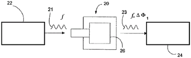
FIGS. 1A-1C are schematic diagrams illustrating the principles of operation of an embodiment of a Thin Film Bulk Acoustic Resonator (TFBAR) sensing device.
Figure 2 is a schematic diagram showing the components of a TFBAR system for detecting an analyte.
Figures 3A-D are schematic diagrams illustrating one embodiment of signal amplification on a surface of a Thin Film Resonator (TFR).
Fig. 4A-D are schematic diagrams illustrating one embodiment of signal amplification on a TFR surface.
FIG. 5A-B is a schematic representation of one embodiment of a first binding partner (5A) bound to the surface of a TFR and a recognition component (5B) bound to a second binding partner linked to the first binding partner,
FIG. 6A is a graph of direct analyte binding and enzyme amplified analyte binding response over time on one embodiment of a TFBAR.
Fig. 6B is a diagram illustrating details of a portion of the diagram given in fig. 4A.
Figure 7 is a schematic diagram illustrating one embodiment of the various polynucleotide components bound to a TFR surface as described in example 2.
The schematic drawings are not necessarily drawn to scale. Like numbers used in the figures refer to like parts, steps, etc. It should be understood, however, that the use of a number to refer to a component in a given figure is not intended to limit the component in another figure to be labeled with the same number. Additionally, the use of different numbers to refer to components is not intended to indicate that the different numbered components cannot be the same or similar.
Detailed Description
In the following detailed description, several specific embodiments of compounds, compositions, products, and methods are disclosed. It is to be understood that other embodiments are contemplated and may be made without departing from the scope or spirit of the present disclosure. The following detailed description is, therefore, not to be taken in a limiting sense.
The present disclosure relates generally, inter alia, to methods, devices, sensors, and systems for detecting analytes. The methods, devices, sensors, and systems use Thin Film Bulk Acoustic Resonators (TFBARs) that measure changes in the frequency or phase of the resonator caused by binding of an analyte on the resonator surface. The binding signal is enhanced by amplifying the component-mediated mass loading. An input electrical signal having a phase and a frequency within the resonance band of the piezoelectric resonator (which in the case of some embodiments of the present disclosure may be about 500 MHz or greater, e.g., about 1.5GHz or greater) is coupled to and transmitted through the resonator to produce an output electrical signal that exhibits a frequency shift or phase shift relative to the input signal due to binding, deposition, etc. of the material being detected on the resonator surface and amplification due to mass loading mediated by the amplifying component. The output electrical signal received from the piezoelectric resonator is analyzed to determine the change in frequency or phase caused by mass deposition mediated by binding and amplification components of the analyte on the resonator surface. The measured change in frequency or phase provides quantitative information about the analyte (or labeled analyte molecule) bound to the resonator surface.
Sensor, device and system
The sensors disclosed herein include at least one thin film resonator sensor, such as a Thin Film Bulk Acoustic Resonator (TFBAR) sensor. A TFBAR sensor includes a piezoelectric layer, or piezoelectric substrate, and input and output transducers. TFBAR sensors are small sensors making the technology suitable for handheld devices. Accordingly, handheld devices for detecting a target analyte comprising a sensor as described herein are contemplated.
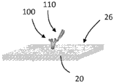
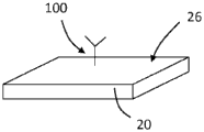
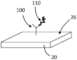
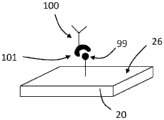
Turning now to the drawings, and referring to FIGS. 1A and 1B, the general operating principles of one embodiment of a bulk acoustic wave piezoelectric resonator 20 for use as a sensor for detecting an analyte are illustrated. The resonator 20 typically comprises a planar layer of piezoelectric material to which are attached on opposite sides two respective metal layers forming the electrodes of the resonator. When the resonator is driven by a signal within the resonance band of the resonator, the two surfaces of the resonator are free to undergo vibrational motion. When the resonator is used as a sensor, then at least one of its surfaces is adapted to provide binding sites for the material to be detected. The binding of the material on the resonator surface changes the resonance characteristics of the resonator and the change in resonance characteristics is detected and interpreted to provide quantitative information about the detected material.
As an example, such quantitative information may be obtained by detecting changes in the insertion or reflection coefficient phase shift of the resonator caused by the incorporation of the material being detected on the resonator surface. Such sensors are different from those that operate a resonator as an oscillator and monitor changes in the oscillation frequency. Instead, such sensors insert the resonator in the path of the preselected frequency signal and monitor changes in the insertion or reflection coefficient phase shift caused by the binding of the material being detected on the resonator surface. Of course, sensors that monitor changes in the oscillation frequency may also be employed in accordance with the signal amplification described herein.
In more detail, FIG. 1A shows the resonator 20 before the material being tested is bonded to its surface 26. The depicted resonator 20 is electrically coupled to a signal source 22, the signal source 22 providing an input electrical signal 21 having a frequency f within the resonance band of the resonator. The input electrical signal is coupled to the resonator 20 and passes through the resonator to provide an output electrical signal 23. In the depicted embodiment, the output electrical signal 23 is at the same frequency as the input signal 21, but is out of phase with the input signal by a phase shift Depending on the piezoelectric properties and physical dimensions of the resonator. The output signal 23 is coupled to a
 phase detector 24, the phase detector 24 providing an interpolation phase shift dependentA phase signal.
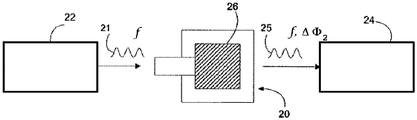
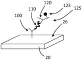
FIG. 1B shows the sensing resonator 20 with the material being detected incorporated on its surface 26. The same input signal is coupled to the resonator 20. Since the resonance characteristics of the resonator change due to the material combination as a perturbation, the insertion phase shift of the output signal 25 becomes . The change in insertion phase shift due to the bonding of the materials is detected by
 phase detector 24. The measured phase shift change is related to the amount of material bound on the resonator surface.
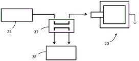
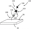
Fig. 1C shows an alternative to measuring the insertion phase of the resonator. A directional coupler (directional coupler)27 is added between the signal source 22 and the resonator 20, with the opposite electrode grounded. The phase detector 28 is configured to measure the phase shift of the reflection coefficient as a result of the material bonded to the resonator surface.
Other TFBAR PHASE SHIFT sensors that may be used with the signal amplification aspects described herein include those described in, FOR example, U.S. patent No. 8,409,875 entitled "RESONATOR operation FREQUENCY OPTIMIZATION FOR PHASE SHIFT monitoring sensor," which is incorporated herein by reference to the extent not inconsistent with the disclosure herein. For example, the sensor device may include: (i) a sensing resonator comprising a binding site for an analyte; (ii) a drive circuit configured to drive the sensing resonator into an oscillating motion; (iii) a measurement circuit arranged to be coupled to the sensing resonator and configured to measure one or more resonator output signals indicative of a resonant characteristic of the oscillatory motion of the sensing resonator; and (iv) a controller operably coupled to the drive and measurement circuitry. The controller may interface with a data store containing instructions that, when executed, cause the controller to adjust the frequency at which the drive circuit drives the sensing resonator to maintain the resonance point of the sensing resonator. Thus, sensing can be achieved as follows: driving the TFBAR to perform an oscillating motion; measuring one or more resonator output signals representative of a resonant characteristic of the oscillatory motion of the TFBAR; and adjusting a driving frequency of the sensing resonator to maintain a resonance point of the TFBAR. In an embodiment, the frequency at which the drive circuit drives the sense resonator is the frequency of the maximum group delay.
Such a phase detection method can be advantageously used for piezoelectric resonators having different resonance frequencies.
In various embodiments, TFBARs for use in the methods, devices, and systems described herein have a resonant frequency of about 500 MHz or greater, such as about 700 MHz or greater, about 900 MHz or greater, about 1 MHz or greater, 1.5GHz or greater, about 1.8GH or greater, about 2 GHz or greater, 2.2 GHz or greater, 2.5 GHz or greater, about 3 GHz or greater, or about 5GHz or greater, which when used with amplification element-mediated mass loading can provide enhanced sensitivity, as will be described in greater detail below. In embodiments, the TFBAR has a resonant frequency from about 500 MHz to about 5GHz, such as from about 900 MHz to about 3 GHz, or from about 1.5GHz to about 2.5 GHz. Some of these frequencies are significantly higher than the frequencies of the piezoelectric resonators previously described.
The sensing resonator described herein is a thin film resonator. Instead of using, for example, AT-cut quartz, a thin-film resonator includes a thin layer of piezoelectric material deposited on a substrate. The piezoelectric film typically has a thickness of less than about 5 microns, for example, less than about 2 microns, and may have a thickness of less than about 100 nanometers. Thin film resonators are generally preferred because of their high resonant frequency and theoretically higher sensitivity. Depending on the application, the thin film resonator used as the sensing element may be formed to support longitudinal or shear bulk acoustic wave resonant modes. Preferably, the sensing elements are formed to support shear bulk acoustic wave resonant modes, as they are more suitable for use in liquid samples.
Additional details regarding sensor devices and systems that may employ TFR are described, for example, in U.S. patent No. 5,932,953 to Drees et al, 8/3, 1999, which is incorporated herein by reference in its entirety to the extent not inconsistent with the disclosure herein.
The TFR sensor may be made in any suitable manner and of any suitable material. By way of example, the resonator may include a substrate such as a silicon wafer or sapphire, a Bragg mirror layer or other suitable acoustic isolation device, a bottom electrode, a piezoelectric material, and a top electrode.
Any suitable piezoelectric material may be used for TFR. Examples of suitable piezoelectric substrates include lithium tantalate (LiTaO)3) Lithium niobate (LiNbO)3) Zinc oxide (ZnO), aluminum nitride (AlN), lead zirconate titanate (PZT), and the like.
The electrodes may be formed of any suitable material, such as aluminum, tungsten, gold, titanium, molybdenum, and the like. The electrodes may be deposited by vapor deposition, or may be formed by any other suitable process.
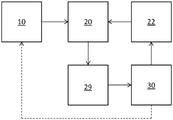
Any suitable device or system may employ a thin film resonator and amplification as described herein. By way of example and with reference to fig. 2, a system for detecting an analyte may include a container 10 (or more than one container), a thin-film resonator 20, a drive circuit 22, a measurement circuit 29, and control electronics 30. A fluid path connects the one or more containers 10 to the resonator 20. The control electronics 30 are operatively coupled to the drive circuitry and the measurement circuitry. In an embodiment, the control electronics 30 are configured to vary the frequency at which the drive circuit 22 oscillates the resonator 20 based on input from the measurement circuit 29.
Still referring to fig. 2, the container 10 (or more than one container) may contain the amplifier molecule, the second recognition component or components thereof to which the amplifier element is attached, and optionally one or more of a tag, an analyte molecule, and a first recognition component. Each of these agents is described in more detail below. The control electronics 30 may control the flow of such agents from the container 10 to the resonator 20; such as by a pump, vacuum, etc.
Any suitable control electronics 30 may be employed. For example, the control electronics may include a processor, controller, memory, and the like. The memory may include computer readable instructions that, when executed by the processor or controller, cause the device and control electronics to perform various functions attributed to the device and control electronics described herein. The memory may include any volatile, non-volatile, magnetic, optical, or electrical media, such as Random Access Memory (RAM), read-only memory (ROM), non-volatile RAM (NVRAM), Electrically Erasable Programmable ROM (EEPROM), flash memory, or any other digital media. The control electronics 30 may include any one or more of a microprocessor, controller, Digital Signal Processor (DSP), Application Specific Integrated Circuit (ASIC), Field Programmable Gate Array (FPGA), or equivalent discrete or integrated logic circuitry. In some examples, control electronics 30 may include components such as any combination of one or more microprocessors, one or more controllers, one or more DSPs, one or more ASICs, or one or more FPGAs, as well as other discrete or integrated logic circuitry. The functionality attributed to the control electronics herein may be embodied in software, firmware, hardware, or any combination thereof.
Molecular recognition and signal amplification
Molecular recognition of samples containing significant background signals can be facilitated by amplification of the signal. The sensors, systems, and methods described herein employ a second recognition component that includes an amplification element, such as a ligase. At the higher frequency ranges described herein, TFBAR sensors respond very effectively to the increase in mass of the sensor surface due to precipitation of the substrate cleaved by the enzyme.
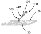
Referring now to FIGS. 3A-D, schematic diagrams showing the amplification of the enzyme on the TFBAR are shown. As shown in fig. 3A, a molecular recognition component 100 configured to bind an analyte is immobilized on the surface 26 of the resonator 20. The resonator 20 with the immobilized molecular recognition component 100 can be contacted with a composition comprising an analyte 110, and the analyte 110 can bind to the molecular recognition component 100 (see fig. 3B). The resonator 20 with the immobilized molecular recognition component 100 bound to the analyte 110 can be contacted with a composition comprising a second molecular recognition component 120 linked to an amplification element 130, such as an enzyme. The second molecular recognition component 120 is configured to bind to the analyte 110 such that the second molecular recognition component 120 and the attached amplification elements 130 are immobilized relative to the surface 26 (see fig. 3C). In the depicted embodiment, the soluble substrate 140 can be converted to an insoluble product 150 by the amplifying component 130, precipitate, and accumulate on the surface 26 of the sensor 20, thereby amplifying the mass signal as a function of the amount or concentration of bound analyte 110 (see FIG. 3D).
It should be appreciated that the series of events depicted in fig. 3A-3D are shown for illustrative purposes, and that any other suitable sequence of events may be employed. For example, the analyte 110 may be contacted with the second molecular recognition component 120 (and the bound amplification elements 130) before the analyte (with the bound second molecular recognition component) is contacted with the surface 26 of the resonator 20 (the molecular recognition component 100 is immobilized relative to the surface 26 of the resonator 20). The substrate 140 may be present at the same time as the addition of the second molecular recognition component 120-amplifying component 130 or may be added later. In any case, washing may be performed prior to amplification.
Non-limiting examples of target analytes include nucleic acids, proteins, peptides, antibodies, enzymes, carbohydrates, chemical compounds, or infectious species such as bacteria, fungi, protozoa, viruses, and the like. In certain applications, the target analyte is capable of binding more than one molecular recognition component.
Any suitable molecular recognition component (e.g., 100 in fig. 3) may be bound to the resonator surface. The molecular recognition component preferably selectively binds to the analyte of interest. For example, the molecular recognition component may be selected from nucleic acid, nucleotide, nucleoside, nucleic acid analogues such as PNA and LNA molecules, proteins, peptides, antibodies including IgA, IgG, IgM, IgE, lectins, enzymes, enzyme cofactors, enzyme substrates, enzyme inhibitors, receptors, ligands, kinases, protein a, Poly U, Poly a, polylysine, triazine dyes, boronic acids, thiols, heparin, polysaccharides, coomassie blue, azure a, metal binding peptides, sugars, carbohydrates, chelators, prokaryotic cells, and eukaryotic cells.
Any suitable method for immobilizing a molecular recognition component on the surface of a TFBAR may be used. For example, a vapor deposition process can be used to deposit a uniform coating of epoxy silane on the sensor surface. Test and control molecular recognition components (e.g., antibodies) can then be deposited onto the test and control resonators using, for example, piezoelectric-based nano-dispensing techniques. The primary amine on the antibody reacts with the epoxy group that covalently binds the antibody to the sensor surface. As another example, the thiol group of the molecular recognition component, if present, binds to the TFBAR surface. The TFBAR surface may be modified as necessary to allow binding of molecular recognition components.
Any suitable molecular recognition component, such as those described above, may be used as the second molecular recognition component (e.g., 120 in fig. 3). The second molecular recognition component may be linked to any suitable amplification element, such as an enzyme. Preferably, the second molecular recognition component is an antibody and the amplifying component is an enzyme.
Any suitable amplification element may be attached to the second molecular recognition component. In embodiments, the amplifying component is an activatable polymerization initiator, such as a photoinitiator, a chemical initiator, or a thermal initiator. The polymerization initiator may be activated in the presence of one or more monomers to graft the polymer from the second molecular recognition component. In embodiments, the amplifying component is an enzyme. In embodiments, the enzyme is capable of converting a substrate that is soluble in the assay environment to an insoluble product that precipitates on the sensor surface. Examples of suitable enzymes include alkaline phosphatase (ALP), horseradish peroxidase (HRP), beta-galactosidase, and glucose oxidase.
Examples of enzyme/substrate systems capable of producing insoluble products capable of accumulating on the surface of the TFBAR include alkaline phosphatase and 5-bromo-4-chloro-3-indolyl phosphate/nitro blue tetrazolium chloride (BCIP/NBT). Enzymatic catalytic hydrolysis of BCIP produces insoluble dimers, which can precipitate on the sensor surface. Other similar substrates having phosphate moieties substituted with such hydrolytically dissociable functional groups such as galactose, glucose, fatty acids, fatty acid esters, and amino acids may be used with their complementary enzymes. Other enzyme/substrate systems include peroxidases, such as horseradish peroxidase (HRP) or myeloperoxidase, and one of the following: benzidine, benzidine dihydrochloride, diaminobenzidine, o-tolidine, o-dianisidine and tetramethylbenzidine, carbazole, in particular 3-amino-9-ethylcarbazole, and various phenolic compounds, all of which are reported to form precipitates upon reaction with peroxidase. In addition, oxidases such as alpha-hydroxy oxidase, aldehyde oxidase, glucose oxidase, L-amino acid oxidase and xanthine oxidase can be used with oxidizable substrate systems such as phenazine methosulfate-nitroblue tetrazolium (phenazine methosulfate-nitroblue tetrazolium) mixtures.
It should be understood that any type of competition assay may be employed. It will also be appreciated that the analyte may be modified to include a tag, for example a streptavidin tag, which is recognised by the first or second recognition complex; a biotin tag; a chitin-binding protein tag; a maltose binding protein tag; a glutathione-S-transferase tag; a poly (His) tag; epitope tags, such as the Myc tag, the HA tag, or the V5 tag; and the like. It will also be appreciated that the analyte to which the tag is attached may include variants or derivatives of the analyte. The variant or derivative is one that can be configured to selectively recognize the first or second molecular recognition component of the analyte. In some cases, it may be desirable that the affinity of the variant or derivative analyte for the first or second molecular recognition component is different from the affinity of the analyte without the tag attached. The variant or derivative of the analyte may be one that allows for easy manufacture of the tag-attached analyte. For example, the tag-linked analyte may comprise a recombinant polypeptide or the like
When performing a competition assay using the tag-attached analyte molecules, instead of or in addition to the analyte, may bind to the first molecular recognition component immobilized on the resonator surface.
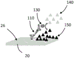
Referring now to fig. 4, an embodiment of a signal amplification assay is described. Many of the components of fig. 4 are the same as or similar to the components shown in fig. 3. If no specific element of FIG. 4 is discussed in detail, reference is made to this numbered element of FIG. 3 above. The signal amplification element 130 may be coupled to the second recognition component 120 at any suitable time. In some embodiments (not shown in fig. 4), the signal amplification element 130 is attached to the second recognition component 120 prior to contact with the analyte 110 or the labeled analyte molecule. In some such embodiments, the signal amplification element 130 is covalently bound to the second recognition component 120.
In some embodiments (e.g., as shown in fig. 4C-D), signal amplification element 130 is attached to second recognition component 120 after second recognition component 120 is contacted with analyte 110 or the tag-attached analyte. For example, the second recognition component 120 can include a first binding partner 123 configured to selectively bind to a second binding partner of the signal amplification element 130. The first binding partner 123 is preferably covalently bound to the second recognition component 120. The second binding partner 135 is preferably covalently bound to the signal amplification component 130. The first 123 and second 135 binding partners preferably bind with high affinity.
Any suitable combination of first 123 and second 135 binding partners may be used. As an example, the second recognition component 120 can be biotinylated, and the signal amplification element 130 can be conjugated to streptavidin; or vice versa. As another example, one of the first and second binding partners may be a polyhistidine (His) tag, and the other of the first and second binding partners may be, for example, a nickel or copper chelator, such as iminodiacetic acid (Ni-IDA) and nitrilotriacetic acid (Ni-NTA) for nickel and carboxymethylaspartic acid (Co-CMA) for cobalt, where the poly (His) tag may be bound with micromolar affinity. Generally, nickel-based resins have a high binding capacity, while cobalt-based resins provide the highest purity. As yet another example, one of the first and second binding partners may be a glutathione-S-transferase (GST) tag and the other of the first and second binding partners may be glutathione. As yet another example, one of the first and second binding partners may be a protein tag that binds maltose and the other of the first and second binding partners may be amylose or maltose. As another example, one of the first and second binding partners may be a protein tag that binds chitin and the other of the first and second binding partners may be chitin. It will be appreciated that the binding partners provided above are merely examples of high affinity binding partners that may be conjugated to the second recognition component or signal amplification element, and that other binding partners are contemplated herein. Furthermore, it will be appreciated that more than one set of binding partners may be employed to link the second recognition component to the signal amplification element.
The binding partner may be conjugated to the second recognition component or signal amplification element by any suitable technique. For example, the binding partner may optionally be linked to a second recognition component or signal amplification element using chemical conjugation or recombinant techniques. Such techniques are well known to those skilled in the art. For example, heterobifunctional (heterobifunctional) crosslinkers utilizing NHS-ester and maleimide functional groups may be used as is well known to those skilled in the art.
It will be appreciated that if the signal amplification element and the second recognition component comprise complementary binding partners, the signal amplification element may be linked to the second recognition component via the binding partners at any suitable time. For example, as shown in fig. 4C-D, signal amplification element 130 may be attached to second recognition component 120 after second recognition component 120 is contacted with analyte 110 or a labeled analyte. In some embodiments, the signal amplification element 130 comprising the second binding partner 135 is contacted with the second recognition component 120 comprising the first binding partner 123 prior to contacting the second recognition component 120 with the analyte 110 or tag-attached analyte or while the second recognition component 120 is introduced into the resonator.
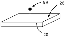
Referring now to fig. 5A-B, a first molecular recognition component 100 may be bound to surface 26 of TFBAR20 via one or more intermediates. For example, a first binding partner 99 may bind to the surface 26, and the first molecular recognition component 100 may include a second binding partner 101 configured to selectively bind to the first binding partner 99. The binding partners 99, 101 may be binding partners as described above (e.g., with respect to fig. 4). First recognition component 100 can be bound to surface 26 via binding partners 99, 101 at any suitable time, such as before sensor 20 is incorporated into a device or system, or after sensor 20 is incorporated into a device or system. For example, as a first step of or during an analyte detection assay, the first recognition component 100 may be bound to the surface 26 via the binding partners 99, 101.
Amplification component-mediated mass loading/signal amplification of TFBAR
It has been noted that as the resonant frequency increases, the sensitivity of mass detection should also increase. However, this is not always observed in practice. Theoretically, a TFBAR having a resonant frequency of about 2.2 GHz should provide sufficient sensitivity to detect low concentrations of analyte without the use of signal amplification/mass loading as described herein. However, the inventors have found that even with such high resonance frequencies, TFBAR sensors are not sensitive enough to detect low levels of analyte. However, by utilizing the amplification/mass loading techniques described herein, more theoretical gain in sensitivity imparted by operating at higher frequencies can be achieved.
The sensitivity to noise is related to the signal propagation discussed theoretically above. At higher frequencies, the signal travels a shorter distance, creating a proximity filter. That is, you only measure substances adjacent to the surface. However, the substances that make up the nearby locations will vary with frequency and can have significant practical ramifications in terms of susceptibility to background noise. Operating with a mass load at higher frequencies results not only in enhanced signal sensitivity, but also in lower sensitivity to noise. This can translate functionally to, for example, less stringent washing requirements, as the amplifier-linked second molecular recognition component that is not bound to the resonator surface (e.g., via analyte binding to the first molecular recognition component) should not add significant mass adjacent to the resonator surface. Furthermore, it was found that the wash requirement to obtain a stable baseline reading in negative samples was less stringent for higher frequency TFBARs, which may also be due to shorter signal propagation distances at higher frequencies.
Surprisingly, it has been found that greater signal amplification is observed at higher frequencies than at lower frequencies. See, e.g., table 2 in the examples below, where greater signal amplification with enzyme-mediated mass loading (relative to direct binding) was observed at 2250MHz compared to the 900 MHz resonator. It was unexpected that a greater level of signal amplification could be achieved at higher frequencies because the different resonators (900 MHz and 2250 MHz) were constructed to contain the same concentration or amount of the first recognition component, the assay used the same concentration and amount of analyte, and the same concentration and amount of enzyme-linked second molecular recognition component and substrate were used. Thus, in theory, the amount of amplification that is expected to actually occur is the same (the amount of product that is expected to precipitate on the surface is the same). However, a greater amount of signal amplification is observed at higher frequencies.
Use of
The sensors, devices, and systems described herein can be used to detect an analyte in a sample. The sensors may be used in numerous chemical, environmental, food safety or medical applications. By way of example, the sample to be tested may be or may be derived from blood, serum, plasma, cerebrospinal fluid, saliva, urine, and the like. Other test compositions that are not fluid compositions may be dissolved or suspended in an appropriate solution or solvent for analysis.
Definition of
Unless defined otherwise, all scientific and technical terms used herein have the meanings commonly used in the art. The definitions provided herein are to facilitate understanding of certain terms used frequently herein and are not meant to limit the scope of the present disclosure.
As used in this specification and the appended claims, the singular forms "a", "an", and "the" include embodiments having plural referents unless the context clearly dictates otherwise.
As used in this specification and the appended claims, the term "or" is generally employed in its sense including "and/or" unless the context clearly dictates otherwise. The term "and/or" means one or all of the listed elements or a combination of any two or more of the listed elements.
As used herein, "having," including, "" containing, "" contains, "" containing, "and the like are used in their open-ended sense and generally mean" including, but not limited to. It should be understood that "consisting essentially of", "consisting of", and the like are included in "including" and the like. As used herein, "consisting essentially of ….. when referring to compositions, products, methods, and the like, means that the components of the compositions, products, methods, and the like, are limited to the listed components and any other components that do not materially affect the basic and novel characteristics of the compositions, products, methods, and the like.
The words "preferred" and "preferably" refer to embodiments of the invention that may provide certain benefits under certain circumstances. However, other embodiments may also be preferred, under the same or other circumstances. Furthermore, the recitation of one or more preferred embodiments does not imply that other embodiments are not useful, and is not intended to exclude other embodiments from the scope of the disclosure (including the claims).
Also herein, the recitation of numerical ranges by endpoints includes all numbers subsumed within that range (e.g. 1 to 5 includes 1, 1.5, 2, 2.75, 3, 3.80, 4, 5, etc. or a value of 10 or less includes 10, 9.4, 7.6, 5, 4.3, 2.9, 1.62, 0.3, etc.). When a range of values is "at most" a particular value, that value is included in the range.
Any directions mentioned herein, such as "top," "bottom," "left," "right," "up," "down," and other directions and orientations are described herein with reference to the drawings for clarity and do not limit the actual device or system or the use of the device or system. A device or system as described herein may be used in a variety of directions and orientations.
As used herein, a "binding event" refers to the binding of a target analyte to a molecular recognition component immobilized in a sensor surface.
Examples
The following non-limiting examples are presented to more fully describe the manner in which the above-described sensors, methods, devices and systems can be used. It should be understood that these examples are in no way intended to limit the scope of the present disclosure or the claims that follow, but are presented for purposes of illustration.
Example 1: proof of concept of enzyme amplification
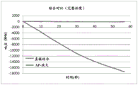
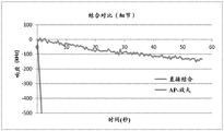
Preliminary proof of concept studies were performed using an anti-bovine IgG assay with alkaline phosphatase (ALP) as conjugating enzyme and BCIP/NBT as precipitating substrate. Briefly, goat anti-cow and goat anti-rat antibodies were immobilized on test and reference resonators by dispensing a 350 μm spot on an epoxy silane coated sensor with a resonant frequency of 2.2 GHz using a piezoelectric dispenser. The sensor was incubated overnight at 4 ℃ in a high humidity environment. The sensors were blocked with fish skin gelatin prior to testing. The reference signal is then subtracted from the test signal and the delta signal is used as the binding response. All tests were performed using sensors immersed in microtiter plates. Sample stirring was achieved by using a stir bar. The test sequence was as follows, exposing the sensor to 1 μ g/ml bovine IgG for 60 seconds, followed by rinsing for 30 seconds and exposure to rabbit anti-bovine IgG-alkaline phosphatase conjugate for 60 seconds. The sensors were then rinsed 2 times for 30 seconds and exposed to BCIP/NBT substrate for 60 seconds. The sensor is electrically connected to a network analyzer that monitors the frequency offset of the device. In this case, the phase that produces the largest group delay is tracked and the change in input frequency that maintains that phase as the mass changes is determined. A 50MHz window around the resonant frequency was collected at a sampling rate of 2 samples per second for the test and reference resonators. This data is post-processed to determine the frequency offset as a function of time for both the test and reference resonators. The frequency shift observed from direct antigen binding was then compared to the signal observed in the enzyme substrate.
The results of this initial study are shown in fig. 4A, and fig. 4B is a detailed view of a portion of the graph presented in fig. 4A. As shown, ALP-enzyme amplification resulted in a significant improvement in sensitivity relative to direct binding without substrate addition. As shown in table 1 below, as a result of the enzyme amplification, a response and a slope exceeding 100-fold amplification were observed.
Table 1: ALP-amplified results
| Direct bonding | Enzyme amplification | |
| Response (integration) | -9,024 | -1,094,473 |
| Amplification (multiple) | 121 | |
| Slope of | -3.24 | -374.77 |
| Slope amplification | 115.71 |
Similar studies were performed using an anti-bovine IgG assay and horseradish peroxidase (HRP) as conjugating enzyme. The precipitating substrates in this reaction were hydrogen peroxide and p-hydroxycinnamic acid (data not shown). Further analysis of ALP enhancement with BCIP/NBT using an anti-rat IgG assay was also performed (data not shown). Subsequent work with ALP and BCIP/NBT systems included various other evaluations.
The benefit of precipitation amplification appears to be frequency dependent. Devices with operating frequencies of 2250MHz and 850 MHz were coated with goat anti-rat F (ab') fragments. The native thiol group on the reduced F (ab') serves to attach to the gold resonator surface, forming a coordinate (dative) thiogold bond. These sensors were then blocked with fish skin gelatin and tested in negative buffer samples or 1 μ g/ml rat IgG, followed by incubation with goat anti-rat alkaline phosphatase conjugated antibodies. The sensor was then rinsed twice and exposed to BCIP/NBT substrate. Data for both direct binding events and substrate amplification were reduced as previously described. Comparison of the 2250MHz TFBAR with the 900 MHz TFBAR demonstrates a 2.5 fold increase in signal amplification with higher frequencies (2250 MHz) relative to the 850 MHz device. In addition, the background levels observed in the 850 MHz device were significantly higher in the negative samples. This is the case when the data is analyzed in kHz/sec response, but the difference becomes more significant when the result is converted to ppm/sec by dividing the frequency shift response by the operating frequency. Adding two additional wash steps before exposing the substrate reduced the amount of background signal in the 850 MHz device to levels comparable to those seen in the 2250MHz device (data not shown).
Table 2: amplified comparison with 850 MHz TFBAR and 2250MHz TFBAR
| Frequency (MHz) | 2250 | 850 |
| Background signal in negative samples (ppm/sec) | -0.86 | -23.11 |
| Direct bonding (kHz/sec) | -3.26 | -0.70 |
| Amplifying signal (kHz/second) | -233.7 | -22.3 |
| Amplification (multiple) | 71.7 | 31.9 |
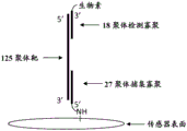
Example 2: demonstration of feasibility of DNA
For binding of DNA to the sensor surface, 10. mu.M of 5 '-amine labeled 27-mer (complementary to the 3' end of the target oligonucleotide) and 10. mu.M of the missense 27-mer were both dissolved in 3X saline-sodium citrate (3X SSC) and spotted on epoxy silane functionalized sensors as test and reference (2150 MHz TFBAR), respectively.
125-mer oligonucleotides were used as model targets. The target oligonucleotide was mixed with 6 nM of 3 'biotin-labeled 18-mer mix buffer (5 XSSC, 10% formamide, 0.1% SDS) complementary to the 5' end of the 125-mer target and reacted with the sensor surface for 4 minutes at 39 ℃.
A schematic of the 27-mer bound to the sensor surface and the target 125-mer bound to the biotinylated 18-mer is shown in FIG. 7.
Two washing steps were then performed (1 XSSC containing 0.01% SDS and HEPES buffered saline plus detergent) and the sensor was exposed to 2. mu.g/ml streptavidin-alkaline phosphatase conjugate from Jackson Immuno (Part Number 016. sup. 050. sup. 084) for 2 minutes in HEPES buffer containing 1 mg/ml Fish Skin Gelatin (FSG).
Two additional washing steps were performed with HEPES plus detergent and the sensor was exposed to the precipitation substrate NBT/BCIP from Thermo (Part Number 34042). Frequency offset data was collected at 39 ℃ for 1.5 minutes and is given in table 3 below. A value of 0.6 pM was obtained using the zero response plus an estimated detection limit of 3 standard deviations.
Table 3: frequency offset data
| DNA target (pM) | Average response (kHz/sec) |
| 0 | 0.93 |
| 0.8 | -0.48 |
| 4 | -2.93 |
| 40 | -38.15 |
| 400 | -111.61 |
Example 3: interleukin-6 (IL-6) two-step immunoassay
Reagent:
affinity purified goat anti-IL-6 (R & DSsystems Part Number AF-206-NA) was spotted onto an epoxy silane activated sensor (2175MHz TFBAR), generally as discussed above for the antibody in example 1.
The anti-IL-6 mouse monoclonal antibody (R & D Systems Part Number MAB206) was labeled with a 5X molar excess of sulfo-NHS-LC-biotin (Thermo Scientific) according to the manufacturer's instructions. Excess unbound biotin reagent was removed by desalting.
The calibrator matrix was prepared by mixing 10% (v/v) chicken serum (Equisech, charcoal removed, heat inactivated) with Phosphate Buffered Saline (PBS) plus 0.1% sodium azide. Calibrators were prepared by diluting recombinant human IL-6(R & D Systems Part Number 206-IL) in a calibrant matrix.
Alkaline phosphatase conjugated streptavidin (SA-ALP) was purchased from Jackson Immuno (Part Number016-050 and 084).
The wash buffer was Hepes buffered saline plus detergent.
The substrate was 1-step NBT/BCIP purchased from Thermo Scientific (Part Number 34042).
And (3) determination:
biotinylated mouse anti-IL-6 was diluted to a working concentration of 8.3. mu.g/mL in Hepes buffer (Hepes/FSG) containing fish skin gelatin.
SA-ALP was diluted in Hepes/FSG to a working concentration of 1. mu.g/mL.
60 μ L of biotinylated mouse anti-IL-6 was mixed with 40 μ L of calibrator and passed back and forth over the sensor for 16 minutes. The reaction mixture was then removed from the microfluidic channel and the SA-ALP was passed back and forth over the sensor for 2 minutes. The sensor was then washed three times with wash buffer, followed by the addition of BCIP/NBT substrate. The rate of change of the resonant frequency during the substrate step is plotted against the IL-6 concentration. The results are shown in table 4 below, including an estimate of the assay sensitivity (zero response plus 3 standard deviations).
Table 4: frequency shift of IL-6 assay

Accordingly, embodiments of a thin film bulk acoustic resonator with signal enhancement are disclosed. Those skilled in the art will appreciate that the guides (leads), devices (such as signal generators), systems, and methods described herein can be practiced with embodiments other than those disclosed. The disclosed embodiments are presented for purposes of illustration and not limitation. It will also be understood that the components of the guide depicted and described with respect to the figures and embodiments herein may be interchangeable.
Claims (13)
1. A method for detecting an analyte in a sample, comprising:
contacting the biological analyte or the biological analyte with the tag-attached analyte molecule, the first recognition component and the amplification element-attached second recognition component to produce a complex comprising the first recognition component and the amplification element-attached second recognition component,
wherein the first recognition component is fixed relative to a surface of a Thin Film Bulk Acoustic Resonator (TFBAR) and is configured to selectively bind one or more of: an analyte, a tagged analyte molecule or tag attached thereto, or any one or more of these molecules bound to a second recognition component, wherein the TFBAR operates at a frequency of 1.8GHz to 4 GHz,
wherein the second recognition component to which the amplification element is attached is configured to selectively bind the analyte, the tagged analyte molecule or tag, or any one or more of these molecules bound to the first recognition component, and;
wherein the second recognition component is conjugated to a first binding partner, the amplifying component is conjugated to a second binding partner configured to selectively bind to the first binding partner, and wherein the amplifying component is linked to the second recognition component by binding between the first and second binding partners;
contacting the linked amplifying component with an amplifying precursor under conditions that convert the amplifying precursor to a mass-increasing molecule at the surface of the TFBAR; and
the mass increase at the surface of the TFBAR was measured.
2. The method of claim 1, wherein the analyte or the analyte and the tag-attached analyte are contacted with a second recognition component having an amplification element attached thereto prior to contacting with the first recognition component immobilized with respect to the surface of the TFBAR.
3. The method of claim 1, wherein the analyte or the analyte and the tag-attached analyte are contacted with the first recognition component prior to contacting with the second recognition component to which the amplification element is attached.
4. The method of claim 1, wherein the analyte or the tag-attached analyte, the first recognition component, and the amplification element-attached second recognition component are contacted simultaneously.
5. The method of any one of claims 1-4, wherein determining the mass added to or bound to the TFBAR surface comprises:
coupling an input electrical signal to the TFBAR, the input electrical signal having a frequency within a resonance band of the piezoelectric resonator, wherein the frequency is 1.8GHz to 4 GHz;
passing the input electrical signal through or across the TFBAR to produce an output electrical signal having a frequency;
receiving an output electrical signal from the TFBAR; and
the change in phase shift of the output electrical signal caused by deposition of the precipitate on the surface of the TFBAR is determined.
6. The method of claim 5, wherein the change in phase shift is a change in insertion or reflection coefficient phase shift.
7. The method of any one of claims 1-4, wherein determining the mass added to or bound to the TFBAR surface comprises:
driving the TFBAR to perform oscillatory motion at the frequency of 1.8GHz to 4 GHz;
measuring one or more resonator output signals representative of a resonant characteristic of the oscillatory motion of the TFBAR; and
the drive frequency of the sense resonator is adjusted to maintain the resonance point of the TFBAR.
8. The method of claim 7, wherein the resonance point of the TFBAR is a point of maximum group delay.
9. The method of claim 5, wherein the frequency is 2 GHz to 4 GHz.
10. The method of claim 5, wherein the frequency is 2 GHz to 2.5 GHz.
11. The method of any one of claims 1-4, wherein the amplifying component is an enzyme and the amplifying precursor is a substrate, and wherein the enzyme is configured to convert the substrate to a precipitate.
12. A system for detecting an analyte in a sample, comprising:
a Thin Film Bulk Acoustic Resonator (TFBAR) comprising a surface having a first recognition component immobilized thereon, wherein the TFBAR operates at a frequency of 1.8GHz to 4 GHz,
the first recognition component is configured to selectively bind the biological analyte, the tag-attached biological analyte molecule, or any of the tags, or any of these molecules bound to the second recognition component to which the amplification element is attached,
the TFBAR has a resonant frequency of 1.8GHz to 4 GHz;
one or more containers containing a magnifying precursor, a second recognition component having a magnifying element attached thereto, and optionally one or more of a tag and an analyte molecule, wherein the second recognition component having a magnifying element attached thereto comprises a second recognition component conjugated to a first binding partner and a magnifying element conjugated to a second binding partner configured to selectively bind to the first binding partner, wherein the magnifying element is attached to the second recognition component by binding of the first and second binding partners and the attached magnifying element is contacted with the magnifying precursor under conditions that convert the magnifying precursor to a molecule of increased mass at the surface of the TFBAR;
a fluid path from the one or more containers to the TFBAR surface bound to the first recognition component;
a drive circuit configured to drive the TFBAR into an oscillating motion;
a measurement circuit arranged to be coupled to the TFBAR and configured to measure one or more resonator output signals representative of a resonance characteristic of the oscillatory motion of the sensing resonator; and
a controller operably coupled to the drive and measurement circuitry.
13. A kit for use with a device for detecting an analyte in a sample, comprising:
a Thin Film Bulk Acoustic Resonator (TFBAR) comprising a surface having a first recognition component immobilized thereon, wherein the TFBAR operates at a frequency of 1.8GHz to 4 GHz,
the first recognition component is configured to selectively bind the biological analyte, the tag-attached biological analyte molecule, or any of the tags, or any of these molecules bound to the second recognition component to which the amplification element is attached,
the TFBAR has a resonant frequency of 1.8GHz to 4 GHz; and
one or more containers containing a magnifying precursor, a second recognition component having a magnifying element attached thereto, and optionally one or more of a tag and an analyte molecule, wherein the second recognition component having a magnifying element attached thereto comprises a second recognition component conjugated to a first binding partner and a magnifying element conjugated to a second binding partner configured to selectively bind to the first binding partner, wherein the magnifying element is attached to the second recognition component by binding of the first and second binding partners and the attached magnifying element is contacted with the magnifying precursor under conditions that convert the magnifying precursor to a molecule that increases mass at the surface of the TFBAR.
Applications Claiming Priority (3)
| Application Number | Priority Date | Filing Date | Title |
|---|---|---|---|
| US201462050589P | 2014-09-15 | 2014-09-15 | |
| US62/050589 | 2014-09-15 | ||
| PCT/US2015/049387 WO2016044055A1 (en) | 2014-09-15 | 2015-09-10 | Thin film bulk acoustic resonator with signal enhancement |
Publications (2)
| Publication Number | Publication Date |
|---|---|
| CN107250794A CN107250794A (en) | 2017-10-13 |
| CN107250794B true CN107250794B (en) | 2020-09-15 |
Family
ID=55533700
Family Applications (1)
| Application Number | Title | Priority Date | Filing Date |
|---|---|---|---|
| CN201580049756.8A Active CN107250794B (en) | 2014-09-15 | 2015-09-10 | Film bulk acoustic resonator with signal enhancement |
Country Status (7)
| Country | Link |
|---|---|
| EP (1) | EP3194961B1 (en) |
| JP (1) | JP6694434B2 (en) |
| CN (1) | CN107250794B (en) |
| DK (1) | DK3194961T3 (en) |
| ES (1) | ES2863602T3 (en) |
| PL (1) | PL3194961T3 (en) |
| WO (1) | WO2016044055A1 (en) |
Families Citing this family (4)
| Publication number | Priority date | Publication date | Assignee | Title |
|---|---|---|---|---|
| US10234425B2 (en) | 2013-03-15 | 2019-03-19 | Qorvo Us, Inc. | Thin film bulk acoustic resonator with signal enhancement |
| WO2014190292A1 (en) | 2013-05-23 | 2014-11-27 | Rapid Diagnostek | Sensors, methods of making and devices |
| WO2014190295A2 (en) | 2013-05-23 | 2014-11-27 | Rapid Diagnostek | Two part assembly |
| EP3818371A4 (en) * | 2018-07-06 | 2022-03-23 | Qorvo Us, Inc. | Bulk acoustic wave resonator with increased dynamic range |
Citations (3)
| Publication number | Priority date | Publication date | Assignee | Title |
|---|---|---|---|---|
| US4999284A (en) * | 1988-04-06 | 1991-03-12 | E. I. Du Pont De Nemours And Company | Enzymatically amplified piezoelectric specific binding assay |
| US5932953A (en) * | 1997-06-30 | 1999-08-03 | Iowa State University Research Foundation, Inc. | Method and system for detecting material using piezoelectric resonators |
| CN103403538A (en) * | 2010-10-20 | 2013-11-20 | 快速诊断技术公司 | Apparatus and method for measuring binding kinetics with a resonating sensor |
Family Cites Families (9)
| Publication number | Priority date | Publication date | Assignee | Title |
|---|---|---|---|---|
| AU2003250294A1 (en) | 2002-07-19 | 2004-03-03 | Siemens Aktiengesellschaft | Device and method for detecting a substance with the aid of a high frequency piezo-acoustic thin film resonator |
| CN100495008C (en) | 2003-06-18 | 2009-06-03 | 中山市泰威技术开发有限公司 | Piezo-electric acoustic wave sensor passive array and its biological chip |
| US20050148065A1 (en) * | 2003-12-30 | 2005-07-07 | Intel Corporation | Biosensor utilizing a resonator having a functionalized surface |
| EP2057461A2 (en) * | 2006-08-17 | 2009-05-13 | Atonomics A/S | Bio surface acoustic wave (saw) resonator amplification for detection of a target analyte |
| KR20090070886A (en) * | 2007-12-27 | 2009-07-01 | 삼성전자주식회사 | A method for amplifying variation of frequency of signal in piezoelectrical biosensor |
| FR2943787B1 (en) * | 2009-03-26 | 2012-10-12 | Commissariat Energie Atomique | MICRO-DEVICE FOR IN SITU DETECTION OF PARTICLES OF INTEREST IN A FLUID MEDIUM, AND METHOD FOR CARRYING OUT SAID METHOD |
| TW201411810A (en) * | 2012-07-16 | 2014-03-16 | Silanna Group Pty Ltd | CMOS fabrication of a thin-film bulk acoustic resonator |
| CN105431734B (en) | 2013-03-15 | 2018-10-02 | 快速诊断技术公司 | The thin film bulk acoustic wave resonator of signal enhancing |
| US10488407B2 (en) * | 2014-09-15 | 2019-11-26 | Qorvo Us, Inc. | Mass detection through redox coupling |
-
2015
- 2015-09-10 JP JP2017533712A patent/JP6694434B2/en active Active
- 2015-09-10 WO PCT/US2015/049387 patent/WO2016044055A1/en active Application Filing
- 2015-09-10 EP EP15842191.7A patent/EP3194961B1/en active Active
- 2015-09-10 DK DK15842191.7T patent/DK3194961T3/en active
- 2015-09-10 PL PL15842191T patent/PL3194961T3/en unknown
- 2015-09-10 ES ES15842191T patent/ES2863602T3/en active Active
- 2015-09-10 CN CN201580049756.8A patent/CN107250794B/en active Active
Patent Citations (3)
| Publication number | Priority date | Publication date | Assignee | Title |
|---|---|---|---|---|
| US4999284A (en) * | 1988-04-06 | 1991-03-12 | E. I. Du Pont De Nemours And Company | Enzymatically amplified piezoelectric specific binding assay |
| US5932953A (en) * | 1997-06-30 | 1999-08-03 | Iowa State University Research Foundation, Inc. | Method and system for detecting material using piezoelectric resonators |
| CN103403538A (en) * | 2010-10-20 | 2013-11-20 | 快速诊断技术公司 | Apparatus and method for measuring binding kinetics with a resonating sensor |
Also Published As
| Publication number | Publication date |
|---|---|
| EP3194961A4 (en) | 2018-03-28 |
| PL3194961T3 (en) | 2021-08-02 |
| JP2017527831A (en) | 2017-09-21 |
| WO2016044055A8 (en) | 2016-05-26 |
| WO2016044055A1 (en) | 2016-03-24 |
| DK3194961T3 (en) | 2021-03-29 |
| EP3194961A1 (en) | 2017-07-26 |
| CN107250794A (en) | 2017-10-13 |
| EP3194961B1 (en) | 2021-01-06 |
| JP6694434B2 (en) | 2020-05-13 |
| ES2863602T3 (en) | 2021-10-11 |
Similar Documents
| Publication | Publication Date | Title |
|---|---|---|
| US10539537B2 (en) | Thin film bulk acoustic resonator with signal enhancement | |
| EP2972295B1 (en) | Thin film bulk acoustic resonator with signal enhancement | |
| JP5020324B2 (en) | A biological surface acoustic wave (SAW) resonator amplification to detect a target analyte | |
| JP5276655B2 (en) | Biological surface acoustic wave (SAW) resonator amplification using nanoparticles for target analyte detection | |
| US7811831B2 (en) | Systems and methods for molecular recognition | |
| CN107250794B (en) | Film bulk acoustic resonator with signal enhancement | |
| US11860129B2 (en) | Bulk acoustic wave resonator with increased dynamic range | |
| US20240033734A1 (en) | Analyte depletion for sensor equilibration | |
| EP3755999A1 (en) | Resonator for the detection of a mass analyte and method for operation of the resonator | |
| US20160291005A1 (en) | Sensors having internal calibration or positive controls | |
| Fourati et al. | Immunosensing with surface acoustic wave sensors: toward highly sensitive and selective improved piezoelectric biosensors | |
| Vijh | Acoustic Wave Based Biosensor | |
| Ha et al. | Study of a piezoelectric SAW immunosensor for the detection of alpha-fetoprotein |
Legal Events
| Date | Code | Title | Description |
|---|---|---|---|
| PB01 | Publication | ||
| PB01 | Publication | ||
| SE01 | Entry into force of request for substantive examination | ||
| SE01 | Entry into force of request for substantive examination | ||
| GR01 | Patent grant | ||
| GR01 | Patent grant |