CN107249743B - Digital microfluidic dilution apparatus, systems, and related methods - Google Patents
Digital microfluidic dilution apparatus, systems, and related methods Download PDFInfo
- Publication number
- CN107249743B CN107249743B CN201580077138.4A CN201580077138A CN107249743B CN 107249743 B CN107249743 B CN 107249743B CN 201580077138 A CN201580077138 A CN 201580077138A CN 107249743 B CN107249743 B CN 107249743B
- Authority
- CN
- China
- Prior art keywords
- electrode
- area
- droplet
- electrodes
- sample
- Prior art date
- Legal status (The legal status is an assumption and is not a legal conclusion. Google has not performed a legal analysis and makes no representation as to the accuracy of the status listed.)
- Active
Links
Images


Classifications
-
- B—PERFORMING OPERATIONS; TRANSPORTING
- B01—PHYSICAL OR CHEMICAL PROCESSES OR APPARATUS IN GENERAL
- B01L—CHEMICAL OR PHYSICAL LABORATORY APPARATUS FOR GENERAL USE
- B01L3/00—Containers or dishes for laboratory use, e.g. laboratory glassware; Droppers
- B01L3/50—Containers for the purpose of retaining a material to be analysed, e.g. test tubes
- B01L3/502—Containers for the purpose of retaining a material to be analysed, e.g. test tubes with fluid transport, e.g. in multi-compartment structures
- B01L3/5027—Containers for the purpose of retaining a material to be analysed, e.g. test tubes with fluid transport, e.g. in multi-compartment structures by integrated microfluidic structures, i.e. dimensions of channels and chambers are such that surface tension forces are important, e.g. lab-on-a-chip
- B01L3/502707—Containers for the purpose of retaining a material to be analysed, e.g. test tubes with fluid transport, e.g. in multi-compartment structures by integrated microfluidic structures, i.e. dimensions of channels and chambers are such that surface tension forces are important, e.g. lab-on-a-chip characterised by the manufacture of the container or its components
-
- B—PERFORMING OPERATIONS; TRANSPORTING
- B01—PHYSICAL OR CHEMICAL PROCESSES OR APPARATUS IN GENERAL
- B01L—CHEMICAL OR PHYSICAL LABORATORY APPARATUS FOR GENERAL USE
- B01L3/00—Containers or dishes for laboratory use, e.g. laboratory glassware; Droppers
- B01L3/50—Containers for the purpose of retaining a material to be analysed, e.g. test tubes
- B01L3/502—Containers for the purpose of retaining a material to be analysed, e.g. test tubes with fluid transport, e.g. in multi-compartment structures
- B01L3/5027—Containers for the purpose of retaining a material to be analysed, e.g. test tubes with fluid transport, e.g. in multi-compartment structures by integrated microfluidic structures, i.e. dimensions of channels and chambers are such that surface tension forces are important, e.g. lab-on-a-chip
- B01L3/502769—Containers for the purpose of retaining a material to be analysed, e.g. test tubes with fluid transport, e.g. in multi-compartment structures by integrated microfluidic structures, i.e. dimensions of channels and chambers are such that surface tension forces are important, e.g. lab-on-a-chip characterised by multiphase flow arrangements
- B01L3/502784—Containers for the purpose of retaining a material to be analysed, e.g. test tubes with fluid transport, e.g. in multi-compartment structures by integrated microfluidic structures, i.e. dimensions of channels and chambers are such that surface tension forces are important, e.g. lab-on-a-chip characterised by multiphase flow arrangements specially adapted for droplet or plug flow, e.g. digital microfluidics
- B01L3/502792—Containers for the purpose of retaining a material to be analysed, e.g. test tubes with fluid transport, e.g. in multi-compartment structures by integrated microfluidic structures, i.e. dimensions of channels and chambers are such that surface tension forces are important, e.g. lab-on-a-chip characterised by multiphase flow arrangements specially adapted for droplet or plug flow, e.g. digital microfluidics for moving individual droplets on a plate, e.g. by locally altering surface tension
-
- B—PERFORMING OPERATIONS; TRANSPORTING
- B01—PHYSICAL OR CHEMICAL PROCESSES OR APPARATUS IN GENERAL
- B01L—CHEMICAL OR PHYSICAL LABORATORY APPARATUS FOR GENERAL USE
- B01L2300/00—Additional constructional details
- B01L2300/06—Auxiliary integrated devices, integrated components
- B01L2300/0627—Sensor or part of a sensor is integrated
- B01L2300/0645—Electrodes
-
- B—PERFORMING OPERATIONS; TRANSPORTING
- B01—PHYSICAL OR CHEMICAL PROCESSES OR APPARATUS IN GENERAL
- B01L—CHEMICAL OR PHYSICAL LABORATORY APPARATUS FOR GENERAL USE
- B01L2300/00—Additional constructional details
- B01L2300/08—Geometry, shape and general structure
- B01L2300/0861—Configuration of multiple channels and/or chambers in a single devices
-
- B—PERFORMING OPERATIONS; TRANSPORTING
- B01—PHYSICAL OR CHEMICAL PROCESSES OR APPARATUS IN GENERAL
- B01L—CHEMICAL OR PHYSICAL LABORATORY APPARATUS FOR GENERAL USE
- B01L2300/00—Additional constructional details
- B01L2300/08—Geometry, shape and general structure
- B01L2300/089—Virtual walls for guiding liquids
-
- B—PERFORMING OPERATIONS; TRANSPORTING
- B01—PHYSICAL OR CHEMICAL PROCESSES OR APPARATUS IN GENERAL
- B01L—CHEMICAL OR PHYSICAL LABORATORY APPARATUS FOR GENERAL USE
- B01L2400/00—Moving or stopping fluids
- B01L2400/04—Moving fluids with specific forces or mechanical means
- B01L2400/0403—Moving fluids with specific forces or mechanical means specific forces
- B01L2400/0415—Moving fluids with specific forces or mechanical means specific forces electrical forces, e.g. electrokinetic
- B01L2400/0427—Electrowetting
Abstract
Exemplary methods, devices, systems for diluting a sample are disclosed. An example method includes depositing a first fluid droplet on a first electrode of a plurality of electrodes. The first electrode has a first area. The first fluidic droplet has a first volume associated with the first area. The exemplary method includes depositing a second fluid droplet on a second electrode of the plurality of electrodes. The second electrode has a second area. The second fluidic droplet has a second volume associated with the second area. The second volume is different from the first volume. The example method includes forming a combined droplet by selectively activating at least one of the first electrode or the second electrode such that one of the first fluidic droplet or the second fluidic droplet merges with the other of the first fluidic droplet or the second fluidic droplet.
Description
RELATED APPLICATIONS
This patent claim is entitled to U.S. provisional patent application No. 62/098,679 filed 2014, 31/35 u.s.c. 119(e), which is hereby incorporated by reference in its entirety.
Technical Field
The present disclosure relates generally to electrode arrays, and more particularly to digital microfluidic dilution devices, systems, and related methods.
Background
Analytical devices typically require dilution of a sample, such as a biological fluid, within a certain concentration level, depending on the analytical sensitivity range of the device. Digital microfluidics enables manipulation of discrete volumes of fluid, including electrokinetic movement, mixing and splitting (splitting) of fluid droplets disposed in a gap between two surfaces, wherein at least one surface comprises an array of electrodes coated with a hydrophobic and/or dielectric material. Dilution using digital microfluidic devices is typically serial dilution, which involves combining a sample droplet with a diluent droplet having substantially equal volume and splitting the combined droplet to achieve a dilution ratio. Serial dilution often produces large and difficult to manipulate droplets, thereby increasing inaccuracies in the dilution process. Serial dilution is also limited with respect to the dilution ratio that can be achieved and requires repeated steps of merging and splitting droplets to achieve the target dilution ratio.
Brief description of the drawings
Fig. 1 is a side view of an exemplary digital microfluidic chip known in the prior art.
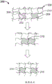
Fig. 2 is a diagram of an exemplary serial dilution process known in the prior art.
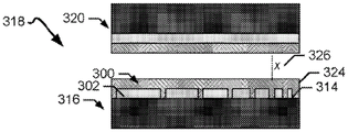
Fig. 3A is a top view of a first exemplary electrode pattern on an exemplary base substrate created via exemplary methods disclosed herein and coupled to an analyzer. Fig. 3B is a side view of a digital microfluidic chip including the first exemplary electrode pattern of fig. 3A.
Fig. 4 is a top view of a second exemplary electrode pattern on an exemplary base substrate created via exemplary methods disclosed herein and coupled to an analyzer.
Fig. 5A is a top view of a third exemplary electrode pattern on an exemplary base substrate, and fig. 5B is a top view of the exemplary base substrate of fig. 5A coupled to an analyzer as an exemplary dilution process performed using the methods and systems disclosed herein.
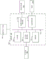
Fig. 6 is a block diagram of an exemplary processing system for patterning an electrode, which may be used to implement examples disclosed herein.
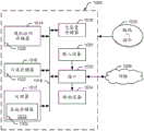
FIG. 7 is a block diagram of an exemplary processing system for dilution that may be used to implement examples disclosed herein.
Fig. 8 is a flow diagram of an example method for creating an electrode pattern that may be used to implement examples disclosed herein.
Fig. 9 is a flow diagram of an exemplary method for diluting a sample that may be used to implement examples disclosed herein.
Fig. 10 is a diagram of a processor platform that may be used with examples disclosed herein.
The figures are not drawn to scale. Rather, the thickness of layers may be exaggerated in the figures to illustrate various layers and regions. Wherever possible, the same reference numbers will be used throughout the drawings and the appended written description to refer to the same or like parts.
Detailed Description
Disclosed herein are methods, systems, and apparatus relating to diluting a sample using a digital microfluidic device. Analytical devices, such as those used for immunoassay analysis, typically have a sensitivity range, which represents the minimum amount of a substance in a sample that can be accurately measured by an assay. The sensitivity range of an analytical device typically requires dilution of a sample (including, for example, a biological fluid sample such as blood, plasma, serum, saliva, sweat, etc.) analyzed using the device to meet a concentration target that falls within the sensitivity range. For example, for a dilution ratio of 0.05 (10/(10 + 200)) or about 20 × dilution, 10 microliters (μ L) of sample may need to be diluted with 200 microliters of diluent.
Digital microfluidic or droplet-based analysis provides for electrically manipulating droplets to break up, merge, and/or transfer the droplets as part of various analyses, including, for example, DNA sequencing and protein analysis. The digital microfluidic device may comprise two surfaces separated by a gap for receiving a droplet. At least one of the surfaces comprises an array of electrodes coated or insulated by a hydrophobic or dielectric material. Fig. 1 shows an exemplary digital microfluidic chip or droplet actuator 100 known in the art, which includes a first or top substrate 102 and a second or bottom substrate 104. The bottom substrate 104 is separated from the top substrate 102 to have a heightxThe gap 106. In the exemplary microfluidic chip 100, the top substrate 102 includes a first non-conductive substrate 108 (e.g., plastic) and a second conductive substrate 110 (e.g., a metal, such as gold, or a non-metallic conductor). In some examples, the second conductive substrate 110 forms a single electrode (e.g., a ground electrode). A hydrophobic and/or dielectric material coats the second conductive substrate 110 to form a first hydrophobic and/or dielectric layer 112. In other examples, the digital microfluidic chip 100 does not include the top substrate 102.
In the exemplary digital microfluidic chip 100, the bottom substrate 104 includes a second non-conductive substrate 114 and at least one electrode 116 formed from a conductive substrate 118. At least one electrode 116 forms an electrode array 120. A hydrophobic and/or dielectric material coats the electrode array 118 to form a second hydrophobic and/or dielectric layer 122. Droplets 124 disposed in the gap 106 can be manipulated on the surface of the hydrophobic and/or dielectric layers 112, 120 by selectively applying an electrical potential to an electrode (e.g., electrode(s) 116 of the electrode array 118) via an electrical source (e.g., a voltage source) to affect the wetting properties of the hydrophobic surface and/or the dielectric surface, e.g., as per an electrowetting or dielectrophoresis process.
The volume of the droplet 124 disposed in the digital microfluidic device 100 is determined by the height of the gap 106xAnd the area of the electrode(s) 116 in the electrode array 118 patterned on the first base substrate 104. Activation of the electrode(s) 116 via application of an electrical potential results in the sample fluid of the droplet 106 covering the activated electrodes due to changes in the wetting properties of the hydrophobic surface of the coated electrode array via electrowetting and/or changes in the force exerted on the dielectric surface of the coated electrode area as part of dielectrophoresis. Due to the gap height of the digital microfluidic chip 100xThe volume of droplet 122 disposed in gap 106, which remains constant, depends on the area of electrode(s) 116 of electrode array 118.
Manipulation of droplets using digital microfluidics can be used as part of a dilution process to dilute a sample within a specific concentration range. Known methods and systems for diluting a sample using digital microfluidics include serial dilution, where a sample droplet is repeatedly merged with a substantially equal volume of a diluent droplet and split (e.g., via manipulation of the droplet on a hydrophobic surface and/or a dielectric surface covering an electrode array) to obtain a droplet with a particular dilution ratio. Serial dilution requires combining and splitting a repeating sequence of droplets to obtain a dilution factor (e.g., final volume relative to diluent volume). For example, to obtain a dilution factor of 8, the merging and splitting process must be performed 3 times. For example, fig. 2 is a diagram of a known serial dilution process 200 using, for example, the digital microfluidic chip 100 of fig. 1. In the serial dilution process 200, a sample droplet 202 is disposed on a first electrode 204 of an electrode array 206. The diluent droplet 208 is disposed on a second electrode 210 of the electrode array 206. In fig. 2, the first electrode 204 and the second electrode 210 have substantially the same area. Thus, assuming that the height of the gap (e.g., gap 106 of fig. 1) in which sample droplet 202 and diluent droplet 208 are disposed is constant, sample droplet 202 and diluent droplet 208 have substantially the same volume.
As shown in fig. 2, the serial dilution process 200 includes merging the sample droplet 202 and the diluent droplet 208 by, for example, applying a potential to the first electrode 204 and the second electrode 210 to move the droplets 202, 208. The merged droplets 202, 208 form a first dilute droplet 212 having a sample concentration that is half that of the sample droplet 202. To achieve further dilution ratios, the serial dilution process 200 includes splitting the first diluent droplet 212 (e.g., by selectively activating one or more electrodes of the electrode array 206) to form second and third diluent droplets 214, 216. The second and third diluent droplets 214, 216 may be combined with additional diluent droplets and split to obtain a target concentration for the sample.
Repeated merging of sample droplets with diluent droplets produces large droplets that are often difficult to manipulate in digital microfluidic chips and do not easily allow for efficient mixing of their own sample with diluent. Furthermore, serial dilution often results in errors being propagated throughout the dilution process. For example, if the combined sample/diluent droplet does not split evenly in half at the first sequence, the sample/diluent ratio in the droplet obtained after this splitting will deviate. Combining these droplets with additional amounts of diluent and further splitting the droplets will amplify the error in the sample dilution ratio as the serial dilution sequence continues. In electrically manipulating the droplets, changes in the surface area of the droplets due to surface tension effects may further lead to inaccurate dilution curves.
Serial dilution is also limited with regard to the dilution ratio that can be achieved. For example, serial dilution can only be passed through 2 n Is achieved by the factor of (1), whereinnIs the number of times a droplet must be combined with diluent and split (e.g., to achieve a dilution factor of 4, a sequence of two combined sample droplets with diluent and split the droplet is required). Thus, serial dilution cannot be achieved, e.g., 3, 5, 6, etcThe dilution factor of (1). Furthermore, only integer dilution factors can be achieved using serial dilution.
Disclosed herein are methods and systems for creating electrodes based on binary sequences (binary sequences) having a surface area that is a fraction of a unit electrode. The exemplary binary system disclosed herein relates to a power series of numbers 2 (e.g., 2)1、22、23、24、25……2 n ). The exemplary system disclosed herein also starts with the number 1 and reflects the number of steps by which the number 1 is multiplied, such that the binary system is 1, 2, 4, 8, 16, 32, 64 …n… series. Creating the electrodes disclosed herein involves patterning the electrodes in an electrode array having a substantially uniform area such that a first or standard unit electrode can be represented in a binary sequence calculated based on a mathematical function as having an electrode dimension of "1", such as 2 n WhereinnAnd = 0. In exemplary binary sequence 2 n In whichnIn the range ofn=0 tonAnd the unit electrode is designated as a relative volume of 64 assuming that the gap height is constant (i.e., a droplet deposited on the unit electrode is considered to have a relative volume of 64 considering the constant gap height and the relative area of the unit electrode). In this example, subsequent electrodes are patterned with an area that is a fraction of the unit electrode area. For example, an electrode represented as a "2" in a binary sequence (e.g., 2)1) There will be an electrode size of 1/2 and a volume of 32 relative to the unit electrode (i.e., a droplet deposited on an electrode is considered to have a relative volume of 32 in view of the constant gap height and electrode size). Thus, in the exemplary methods and systems disclosed herein, electrodes are created based on fractions per electrode area that provide the relative volumes of droplets disposed on the electrodes.
Exemplary methods and systems for diluting a sample using electrodes patterned based on binary sequences are also disclosed herein. Using different sized electrodes, sample and diluent droplets associated with different sized electrodes can be selectively combined to obtain a combination of sample and diluent droplets that results in a particular dilution ratio. Various dilution ratios can be achieved by selectively activating specific electrodes having fractional areas relative to the unit electrode, thereby activating corresponding relative volumes. The dilution ratios created using the methods and systems disclosed herein are not limited to specific integers, integer factors, etc., but may include any dilution ratio that may result from a combination of relative volumes associated with differently sized electrodes. Furthermore, rather than continuously increasing the droplet volume and splitting the droplet, the dilution performed using the disclosed exemplary methods involves collecting the droplet from an activated electrode, selectively pinching off or segmenting the droplet from a larger volume of sample or diluent. Collecting the pinched off droplets rather than repeatedly merging and splitting the droplets reduces surface tension effects and improves efficiency and accuracy compared to serial dilution. For example, in serial dilution, splitting a first droplet to obtain a second droplet having a ratio of 80% diluent to 20% sample fluid may result in a second droplet having a ratio of, for example, 75% diluent to 25% sample fluid due to inaccuracies in splitting the droplets (e.g., failure to verify the accuracy of separation of the first droplet based on diluent and sample fluid volumes). In contrast, collecting a pinched-off portion of diluent and sample fluid as disclosed herein provides a droplet with a more accurate dilution ratio, because pinched-off portions with associated volumes are selectively collected to build dilution droplets as compared to splitting droplets, and thereby substantially eliminating opportunities for inaccuracy.
An example method for diluting a fluid disclosed herein includes depositing a first fluid droplet on a first electrode of a plurality of electrodes. The first electrode has a first area. The first fluid droplet has a first volume associated with the first area. The exemplary method includes depositing a second fluid droplet, different from the first fluid droplet, on a second electrode of the plurality of electrodes. The second electrode has a second area. The second fluidic drop has a second volume associated with the second area. The second volume is different from the first volume. The example method also includes forming a combined droplet by selectively activating at least one of the first electrode or the second electrode to cause one of the first fluidic droplet or the second fluidic droplet to merge with the other of the first fluidic droplet or the second fluidic droplet.
In some examples, the method includes dispensing a third fluid droplet on a third electrode of the plurality of electrodes. The third fluid droplet is substantially identical to one of the first fluid droplet or the second fluid droplet. In some examples, the method includes selectively activating the first electrode and the third electrode, and capturing a portion of the third fluid droplet on the first electrode based on the activation to form a first combined droplet.
In some examples, the second area of the second electrode is a fraction of the first area of the first electrode.
In some examples, the first area of the first electrode is substantially the same as the second area of the second electrode.
In some examples, the method includes activating one or more of a second electrode or a third electrode of the plurality of electrodes to move the second fluid droplet to the third electrode, wherein the third fluid droplet is disposed on the third electrode. The third fluid droplet is different from the second fluid droplet. The second fluid droplet and the third fluid droplet form a second combined droplet. In such examples, the method includes activating at least one of the first electrode or the third electrode and merging the second combined droplet with the first fluidic droplet on the first electrode to form a first combined droplet. Also, in some examples, the third electrode has a third area different from the second area. The third area is a fraction of the first area. In such examples, the volume of the third fluid droplet is different than the volume of the first and second fluid droplets.
In some examples, the method includes mixing the first combined droplet by activating the first electrode.
In some examples, the method includes calculating a dilution ratio for the first combined droplet based on the first volume and the second volume.
In some examples, the method includes transferring the first combined droplet to an analyzer.
Another exemplary method disclosed herein includes patterning a first electrode on a first substrate, the first electrode having a first area. The exemplary method includes patterning a second electrode on a first substrate. The second electrode has a second area. The second area is a fraction of the first area. The example method also includes associating the first electrode with the first volume based on the first area and a height of a gap between the first substrate and the second substrate. The exemplary method includes associating a second electrode with a second volume based on the second area and the height of the gap, wherein the first electrode and the second electrode are represented in a binary sequence based on the first area and the first volume and the second area and the second, respectively.
In some examples, the method includes patterning a third electrode on the first substrate. The third electrode has a third area. The third area is a fraction of the first area. Patterning the third electrode includes nesting the second electrode between the third electrode and the first electrode.
In some examples, the method includes patterning a third electrode on the first substrate. The third electrode has a third area. The third area is a fraction of the first area. Patterning the third electrode includes arranging the first electrode, the second electrode, and the third electrode in order based on a size of the first area, a size of the second area, and a size of the third area.
In some examples, the method includes coating the first electrode and the second electrode with at least one of a hydrophobic material or a dielectric material.
In some examples, the method includes creating a first electrode and a second electrode on a first substrate using one or more of a laser or a lithographic printer.
In some examples, the method includes calculating a binary sequence of the plurality of electrodes relative to the first area of the first electrode.
Also disclosed herein is an exemplary system comprising an electrode array comprising a plurality of electrodes including a first electrode and a second electrode, a first sample droplet of a sample to be disposed on the first electrode, and a first diluent droplet to be disposed on the second electrode. The first sample droplet has a different volume than the first diluent droplet. The exemplary system also includes a calculator to calculate a dilution ratio of the sample. The exemplary system includes a power source to selectively activate at least one of the first electrode or the second electrode to combine the sample droplet and the diluent droplet based on the dilution ratio.
In some examples, the electrode array further includes a third electrode, one of the second sample droplet or the second diluent droplet to be disposed on the third electrode, the one of the second sample droplet or the second diluent droplet having a different volume than the first sample droplet or the first diluent droplet. In such examples, the power source selectively activates the first electrode and at least one of the second electrode or the third electrode based on the respective volumes.
In some examples, the system includes a dispenser to dispense the diluent onto a third electrode in the electrode array. In some such examples, the power source activates the second electrode and the third electrode to form the diluent droplet.
Also disclosed herein are exemplary devices comprising a first substrate and a second substrate. The second substrate is spaced apart from the first substrate. In this exemplary apparatus, an electrode pattern is disposed on a first substrate. The electrode pattern includes a plurality of electrodes including a first electrode having a first area. The other electrodes of the plurality of electrodes each have a respective area relative to the first area. For this electrode pattern, the electrodes are represented in binary sequence.
Also disclosed herein is an example method that includes selectively activating a first electrode having a first area, a second electrode having a second area, and a third electrode having a third area. The first area is greater than the second area and the third area and the second area is greater than the third area. A first droplet having a first volume is disposed on the first electrode, a second droplet having a second volume is disposed on the second electrode, and a third droplet having a third volume is disposed on the third electrode. At least one of the first, second, or third droplets comprises a diluent, and at least one of the first, second, or third droplets comprises a sample. The selective activation causes at least one of the first, second, or third droplets to move relative to the other droplets. The exemplary method includes merging the first droplet, the second droplet, and the third droplet based on selective activation to form a combined droplet, wherein the sample of the combined droplet is diluted based on the first volume, the second volume, and the third volume.
In some examples, the sample is diluted by a non-integer dilution factor.
In some examples, the method includes dispensing a first droplet on the first electrode by selectively activating the first electrode and a fourth electrode, wherein a fourth droplet having a fourth volume greater than the first volume is disposed on the fourth electrode, a portion of the fourth droplet to be distributed onto the first electrode.
In some examples, merging the first droplet, the second droplet, and the third droplet includes moving the first droplet proximate to the second electrode via selective activation. The exemplary method includes segmenting a portion of the second droplet based on the selective activation and combining the first droplet with the portion of the second droplet. In some examples, the method includes moving the first droplet including the portion of the second droplet to a third electrode, and segmenting a portion of the third droplet based on the selective activation. In such examples, the method includes combining the portion of the third droplet with the portions of the first and second droplets to form a combined droplet. Also, in some examples, the method includes returning the combined droplet to the first electrode via selective activation.
An exemplary apparatus disclosed herein includes a first substrate and a second substrate. The second substrate is spaced apart from the first substrate. The exemplary apparatus includes an electrode pattern disposed on a first substrate. The electrode pattern includes a plurality of electrodes including a first electrode having a first area, a second electrode having a first fractional area with respect to the first area, and a third electrode having a second fractional area with respect to the first area. The first area, the first fractional area, and the second fractional area are each different.
In some examples, the first fractional area is one-half of the first area. Likewise, in some examples, the second fractional area is one-fourth of the first area.
In some examples, the electrode pattern further includes a fourth electrode having a third fractional area relative to the first area. In some examples, the third fractional area is substantially equal to one of the first fractional area or the second fractional area.
In some examples, the electrode pattern further includes a fifth electrode having a fourth fractional area relative to the first area.
Also, in some examples, the first area is associated with a first volume of a first droplet disposed on the first electrode, the first fractional area is associated with a second volume of a second droplet disposed on the second electrode, and the second fractional area is associated with a third volume of a third droplet disposed on the third electrode. In such examples, the second and third volumes are based on fractional volumes of the electrode pattern relative to the first volume. In some examples, the second volume is substantially equal to one-half of the first volume.
Turning now to the drawings, fig. 3A is a top view of an exemplary electrode array 300, the exemplary electrode array 300 including a first electrode 302, a second electrode 304, a third electrode 306, a fourth electrode 308, a fifth electrode 310, a sixth electrode 311, a seventh electrode 312, and an eighth electrode 314 patterned on a first or bottom substrate 316 based on a binary sequence, with opposing areas. As will be disclosed hereinafter, the fifth electrode 310 is substantially the same size as the sixth electrode 311. The electrode array 300 may be formed from the conductive material of the bottom substrate 316. The conductive material may include, for example, gold, silver, copper, or a non-metallic conductor such as a conductive polymer. As shown in fig. 3B, the electrode array 300 may be part of a digital microfluidic chip 318 that includes a bottom substrate 316 and a second or top substrate 320.
The electrode array 300 may be used to dilute a sample prior to analysis of the sample by an analyzer 322 (e.g., an immunoassay analyzer). In some examples, electrode array 300 and analyzer 322 are disposed within an analysis device, with electrode array 300 being located in a different portion of the device than analyzer 322. Such an arrangement allows dilution of the sample within a certain concentration in the formulation for analysis by the analyzer 322.
The first through eighth electrodes 302, 304, 306, 308, 310, 311, 312, 314 of the electrode array 300 are formed by patterning an electrode design onto an underlying substrate. Patterning of the first through eighth electrodes 302, 304, 306, 308, 310, 311, 312, 314 may be performed using one or more techniques, including, but not limited to, photolithography, laser ablation (e.g., by iteratively etching a pattern into the substrate via laser wide field blasting) or by laser, thereby exposing the bottom substrate to the laser to form an electrode pattern), inkjet printing, and other methods for creating (e.g., printing) electrodes. The electrode design pattern includes lines and gaps outlining the first to eighth electrodes 302, 304, 306, 308, 310, 311, 312, 314.
After the first through eighth electrodes 302, 304, 306, 308, 310, 311, 312, 314 are created, the electrode array 300 is coated with a hydrophobic and/or dielectric material to form a hydrophobic and/or dielectric layer 324 as shown in fig. 3B via, for example, curing of the material. In some examples, the electrode array 300 is comprised of a portion of the bottom substrate 316. For example, the electrode array 300 may be formed using a roll-to-roll assembly such that a plurality of electrode arrays are formed on the bottom substrate 316 as the bottom substrate 316 moves through the assembly. In such examples, after patterning the electrode design and/or depositing hydrophobic and/or dielectric material on the electrode array(s) 300, the base substrate 316 is cut into discrete portions, each portion comprising an electrode array 300. An example of the fabrication of a digital microfluidic chip is disclosed in U.S. application serial No. 14/687,398, which is hereby incorporated by reference in its entirety.
Respective areas of the first to eighth electrodes 302, 304, 306, 308, 310, 311, 312, 314 are patterned by a binary sequence. As an example, by basing function 2 n (whereinn=0 to 6 are shown in the electrode array 300 of fig. 3) creates the first to eighth electrodes 302, 304, 306, 308, 310, 311, 312, 314 of the electrode array 300. In electrode array 300, first electrode 302 is a standard or unit electrode (e.g., 2) represented by the number "1" in a binary sequence0= 1). The first electrode 302 is assigned a relative electrode size of 1. In some examplesThe first electrode is proximate to the analyzer 322. As will be further disclosed below (e.g., in conjunction with fig. 5), the diluent droplets produced using the first through eighth electrodes 302, 304, 306, 308, 310, 311, 312, 314 move toward the first electrode 302 for transfer to the analyzer 322.
Following the binary sequence, the second electrode 304 is represented by the number "2" in the binary sequence (e.g., 2)1= 2). The second electrode 304 has an electrode size or area of 1/2 relative to the area of the first electrode 302. Similarly, the third electrode 306 is represented by the number "4" in a binary sequence (e.g., 2)2= 4) and has an electrode size or area of 1/4 relative to the area of the first electrode 302. The fourth through eighth electrodes 308, 310, 311, 312, 314 proceed as disclosed above in binary representation (e.g., the fourth electrode 308 is represented by the number "8" in a binary sequence and has an opposite electrode area of 1/8).
For example, the first or unit electrode 302 may have a thickness of 1.65 mm2The area of (a). Compliance 2 n Second electrode 304 has a binary sequence of 0.825 mm2Has a surface area (e.g., 1/2 of the area of the first electrode 302) of 0.4125 mm, and the third electrode 306 has a surface area of 0.4125 mm2Has a surface area (e.g., 1/4 of the area of the first electrode 302), and the fourth electrode 308 has a surface area of 0.20625 mm2E.g., 1/8 of the area of the first electrode 302. Thus, patterning the electrode based on a binary sequence provides an electrode with a surface area that is a fraction of the unit electrode.
The first to eighth electrodes 302, 304, 306, 308, 310, 311, 312, 314 each specify relative volumes in binary sequence. Thus, a droplet disposed on each of the first through seventh electrodes is considered to have a relative volume of the electrode on which the droplet is deposited. For example, using a function based on 2 n (whereinn=0 to 6), the first to seventh electrodes 302, 304, 306, 308, 310, 312, 314 being represented by the numbers 1, 2, 4, 8, 16, 32 and 64, respectively, in the sequence. The first electrode 302 ("1" in the binary sequence) is assigned a relative volume of 64, assuming a constant spacing 326 between the bottom substrate 316 and the second or top substrate 320 of FIG. 3BFixed heightx. The second electrode 304 is assigned a relative volume of 32, the third electrode 306 is assigned a relative volume of 16, and so on, and the seventh electrode 314 is assigned a relative volume of 1. Table 1 below shows the relationship between the representation of the first through seventh electrodes 302, 304, 306, 308, 310, 312, 314 in the binary sequence and the corresponding relative electrode size and relative volume in the exemplary electrode array 300.
Table 1: binary sequence of exemplary electrode array 300
| Electrodes of the |
Binary sequence # | Relative electrode size/area | Relative volumes associated with the electrodes |
| |
1 | 1 | 64 |
| |
2 | 1/2 | 32 |
| |
4 | 1/4 | 16 |
| |
8 | 1/8 | 8 |
| |
16 | 1/16 | 4 |
| Sixth electrode 311 | 16 | 1/16 | 4 |
| Seventh electrode 312 | 32 | 1/32 | 2 |
| Eighth |
64 | 1/64 | 1 |
As shown in table 1, the binary sequence provides a proportional relationship between the respective electrode areas or sizes of the first to eighth electrodes 302, 304, 306, 308, 310, 311, 312, 314 and the volume. The second to eighth electrodes 304, 306, 308, 310, 311, 312, 314 each have an area that is a fraction of the area of the first electrode 302. Further, the first to eighth electrodes 302, 304, 306, 308, 310, 311, 312, 314 are each assigned a relative volume based on their representation in the binary sequence. A droplet disposed on an electrode in a binary sequence may be considered to have a volume corresponding to the relative volume of that electrode.
The electrode array 300 may include more or less electrodes than the first to eighth electrodes 302, 304, 306, 308, 310, 311, 312, 314. In some examples, the electrode array includes at least two of the one or more respective first through eighth electrodes 302, 304, 306, 308, 310, 311, 312, 314. As shown in fig. 3, fifth electrode 310 is substantially the same size as sixth electrode 311 and thus has the same area and corresponding volume (e.g., fifth electrode 310 and sixth electrode 311 each have an area of 1/16 and a relative volume of 4). The sample droplet may be disposed on the fifth electrode 310, and the diluent droplet may be disposed on the sixth electrode 311. As will be disclosed hereinafter, such an arrangement enables the creation of various dilution ratios, as sample and diluent droplets having substantially the same volume can be used to calculate different dilution ratios. Further, the binary sequence is not limited to the exemplary binary sequence described in table 1. More specifically, the relationship between the electrodes may differ based on the selected binary sequence in terms of relative volume and thus relative volume.
The arrangement of the first to eighth electrodes 302, 304, 306, 308, 310, 311, 312, 314 of the electrode array 300 is not limited to the arrangement shown in fig. 3. More specifically, the pattern of the electrodes of the electrode array may be designed based on one or more factors, including the space available on the substrate and/or factors that may affect the performance of the digital microfluidic chip, such as the spacing between the electrodes. Fig. 4 shows an exemplary electrode array 400 comprising a first electrode 402, a second electrode 404, a third electrode 406, and a fourth electrode 408. The second through fourth electrodes 404, 406, 408 each have an area that is a fraction of the first electrode 402 (e.g., a unit electrode) in a binary sequence of the electrode array 400. As shown in fig. 4, the first through fourth electrodes 402, 404, 406, 408 are patterned in a nested configuration on the base substrate 410 such that the second through fourth electrodes 404, 406, 408 at least partially surround one or more other of the second through fourth electrodes 404, 406, 408. The pattern of fig. 4 may be used, for example, to conserve space on the base substrate 410, for example, the size of the analysis devices associated with the electrode array 400 and the analyzer 322. In creating the pattern or design of the electrodes, consideration is given to maintaining the electrode area ratio in a binary sequence. In addition to the patterns shown in fig. 3 and 4, other patterns may be used, including, for example, symmetrical patterns, asymmetrical patterns, irregular patterns, interlocking patterns, repeating patterns and/or any combination of pattern(s), array(s) and/or matrix.
The shapes of the first to eighth electrodes 302, 304, 306, 308, 310, 311, 312, 314 of the electrode array 300 and the first to fourth electrodes 402, 404, 406, 408 of the electrode array 400 are not limited to the shapes shown in fig. 3 and 4. More specifically, the electrode shape can be designed based on one or more factors including the space available on the substrate and/or factors that can affect the performance of the digital microfluidic chip, such as the spacing between electrodes, the electric field generated by the electrodes, and the size of the droplets manipulated by the electrodes, among others. For example, in some instances, one or more electrodes may be square, circular, oval, triangular, diamond-shaped, star-shaped, irregular-shaped, interlocking with one or more other electrodes, and/or any other suitable shape or combination of shapes.
In operation, the binary sequence allows for the creation of a dilution ratio by selectively combining a diluent droplet and a sample droplet disposed on each electrode of the electrode array. In order to deposit or distribute the diluent and sample droplets on one or more of the first through eighth electrodes 302, 304, 306, 308, 310, 311, 312, 314, one or more reservoir or base electrodes (reservoir or base electrodes) 328, 330 are optionally provided proximate the first through eighth electrodes 302, 304, 306, 308, 310, 311, 312, 314. For example, first reservoir electrode 328 may be covered with a pre-dispensed droplet of sample fluid and second reservoir electrode 330 may be covered with a pre-dispensed droplet of diluent fluid, each having a volume greater than the volumes of first through eighth electrodes 302, 304, 306, 308, 310, 311, 312, 314. One or more larger droplets of sample and/or diluent may be dispensed onto the reservoir electrodes 328, 330 via a dispensing device as discussed below in connection with fig. 7. Also, although in fig. 3, the first and second base electrodes 330, 328 are shown adjacent to the electrode array 300, the first and second base electrodes 330, 328 may be located elsewhere in an analytical system that includes the electrode array 300 (e.g., locations that are not adjacent to the electrode array 300).
To deposit the sample fluid on, for example, fifth electrode 310, first reservoir electrode 328 and fifth electrode 310 are activated such that the sample fluid on first reservoir electrode 328 is drawn onto fifth electrode 310. Deactivating the first reservoir electrode 328 may result in pinching off (e.g., separating, fragmenting, or splitting) the sample fluid from the first reservoir electrode 328 to the fifth electrode 310. In some examples, depositing the sample fluid from the first reservoir electrode 328 onto one or more of the first through eighth electrodes 302, 304, 306, 308, 310, 311, 312, 314 includes selectively activating and deactivating the first reservoir electrode 328 and the first through eighth electrodes 302, 304, 306, 308, 310, 311, 312, 314 to draw the sample fluid from the first reservoir electrode 328 onto the smaller electrode and move the sample fluid droplet(s) to the one or more electrodes 302, 304, 306, 308, 310, 311, 312, 314. In instances in which the first reservoir electrode 328 is not positioned adjacent to the electrode array 300, the sample droplet may be moved (via electromanipulation) from the location of the first reservoir 328 to the electrode array 300.
Similarly, to deposit or distribute diluent fluid on, for example, the first electrode 302 and the third electrode 306, the first through eighth electrodes 302, 304, 306, 308, 310, 311, 312, 314 are selectively activated and deactivated to draw diluent fluid from the second reservoir 330 and pinch off or sever diluent to cover the first electrode 302 and the third electrode 306. The diluent fluid may comprise any liquid capable of acting as a diluent, including, for example, a reagent diluent. Likewise, in instances in which the second reservoir electrode 330 is not positioned adjacent to the electrode array 300, the diluent droplet may be moved (via electrical manipulation) from the location of the first reservoir 330 to the electrode array 300.
In some examples, the sample and/or diluent fluid deposited on the first through eighth electrodes 302, 304, 306, 308, 310, 311, 312, 314 has a volume greater (e.g., slightly greater or not significantly greater) than the volume associated with the electrodes such that the sample and/or diluent fluid overhangs one or more of the electrodes (e.g., the droplet extends onto an adjacent electrode). As will be described below, such overhang of droplets may be used to facilitate merging portions of droplets to form diluted droplets.
To obtain a dilution ratio of, for example, 20 using the first to eighth electrodes 302, 304, 306, 308, 310, 311, 312, 314 of the electrode array 300 of fig. 3, a sample droplet was disposed on the fifth electrode 310 having a relative volume of 4 as shown in table 1. Similarly, a droplet of diluent is disposed on the first electrode 302 (having a relative volume of 64), the fourth electrode 308 (having a relative volume of 8), and the sixth electrode 311 (having a relative volume of 4). The diluent droplets disposed on the first electrode 302 are manipulated to collect, combine with, or pick up the sample and diluent fluids disposed on the smaller volume electrode. To collect the sample and/or diluent droplets or portions thereof disposed on the smaller volume electrodes, the diluent droplets of the first electrode 302 are manipulated or pulled (e.g., via selective activation of the electrode array 300) to pick up fluid from the respective fourth 308, fifth 310, and sixth 311 electrodes. For example, a droplet of diluent at the first electrode 302 moves (e.g., via selective electrical manipulation) to the fourth electrode 308. The diluent droplet of the first electrode 302 and the diluent droplet of the fourth electrode 308 are in contact such that the smaller volume diluent droplet of the fourth electrode 308 merges into a larger diluent droplet. In other examples, selective activation of fourth electrode 308 (and/or other electrodes of electrode array 300) may cause a portion of the diluent droplets disposed on fourth electrode 308 to pinch off or break apart from the remaining portion of the diluent droplets disposed on fourth electrode 308. The pinched off portion may be collected by the diluent droplet of the first electrode 302 (e.g., as a result of droplet contact). In a further example, a droplet disposed on the fourth electrode 308 moves (e.g., jumps) to the electrode (or between the electrodes) to be collected by the diluent droplet of the first electrode 302. Also, in some examples, a portion of the sample and/or diluent fluid remains on the smaller volume electrodes after the sample and/or diluent fluid is pinched off or moved from the fourth, fifth, and sixth electrodes 308, 310, 311 (and/or other electrodes of the electrode array 300) and collected by the diluent droplets of the first electrode 302.
When the original diluent droplet of the first electrode 302 is grown by combining the droplet with other sample and diluent droplets, manipulating the droplet on the electrodes of the electrode array may swamp the smaller electrode (e.g., the volume of the combined droplet is greater than the volume of the smaller electrode, such as the fifth electrode 310). However, the collection of a smaller volume sample and diluent droplet via the larger volume diluent droplet of the first electrode 302 prevents droplets having a small volume (such as the droplet associated with the eighth electrode 314) from being stranded or unable to engage other droplets due to the restriction of manipulating small-sized droplets to move between the electrodes. Flooding smaller electrodes with larger volume droplets allows smaller volume droplets to be collected by drawing larger volume droplets across one or more electrodes to pick up smaller volumes. Also, depositing a larger volume (e.g., not a significantly larger volume) of fluid on a smaller electrode results in the fluid overhanging that electrode (e.g., extending onto an adjacent electrode). The overhang prevents droplet retention when the droplet can be manipulated, for example, to move to an adjacent electrode or to be pinched off by activation of another electrode in the vicinity. In instances where a droplet or portion of a droplet remains on the smaller electrode after the selected volume is segmented or pinched off, other droplets of sample and/or diluent may be used to clean the electrodes of the electrode array 300 by collecting the remaining portion (substantially as described above for collecting droplets from a droplet of diluent at the first electrode 302).
After collecting the smaller volume of sample and diluent droplets by the diluent droplet of the first electrode 302, the resulting combined droplet is pulled back (e.g., via selective electrical activation of the electrodes of the electrode array 300) to the first electrode 302. In some examples, the volume of the combined droplet is greater than the volume associated with the first electrode 302. In such examples, the combined droplet overhangs the first electrode 302 (e.g., extends onto an adjacent electrode, such as the second electrode 304). As disclosed above, an overhanging droplet that floods the electrode can enhance the manipulation of the droplet compared to a standard droplet. The combined droplet may be focused on the first electrode 302 by activating the first electrode 302 and deactivating the other electrodes of the electrode array 300.
The resulting combined droplet includes the diluent volumes from the first electrode 302, the fourth electrode 308, and the sixth electrode 311 to obtain a relative diluent volume of 76 (64 +8+ 4). The resulting combined droplet also includes a sample droplet having a fifth electrode 310 with a volume of 4. Thus, the resulting combined droplet has a dilution ratio of 0.05 (4/(4 + 76)), or a dilution factor of about 20 × (e.g., 1 sample, 19 diluents). Thus, creating a device with an electrode array (which includes electrodes having different areas and associated volumes) based on a binary sequence enables the example apparatus, systems, and methods disclosed herein to produce or achieve multiple dilution ratios using different combinations of electrodes of the electrode array.
Fig. 5A is a top view of a third exemplary electrode pattern on an exemplary base substrate, and fig. 5B is a top view of the exemplary base substrate of fig. 5A coupled to an analyzer. Fig. 5A and 5B together illustrate an exemplary dilution process 500 using different sized electrodes created based on a binary sequence. As shown in fig. 5A and 5B, the base substrate 501 includes an electrode array 502 having a plurality of electrodes, including a first electrode 504, a second electrode 506, a third electrode 508, and a fourth electrode 510, a fifth electrode 512, and a sixth electrode 514. As an example, the first through sixth electrodes 504, 506, 508, 510, 512, 514 may be represented by a binary sequence (e.g., function 2 described above in connection with fig. 3 and table 1) n ). In the exemplary electrode array 502, the first electrode 504 and the second electrode 506 are unit electrodes such that the first electrode 504 and the second electrode 506 are each represented by a "1" in a binary sequence and have a corresponding relative area of 1. As also shown in fig. 5A and 5B, the third to sixth electrodes 508, 510, 512, 514 have respective areas that are fractions of the areas of the first electrode 504 and the second electrode 506. As an example, in electrode array 502, third electrode 508 has an opposite area of 1/2 and fourth electrode 510 has an opposite area of 1/16 (e.g., corresponding to the numbers "2" and "16" in the binary sequence of table 1). Hydrophobic and/or dielectric material coating the first to sixth electrodes504. 506, 508, 510, 512, 514 to form a hydrophobic and/or dielectric layer 515.
The dilution process 500 includes a preparation phase 516 (fig. 5A). As an example, fig. 5 shows that during the preparation phase 516, a diluent droplet 518 is deposited on the first electrode 504 of the electrode array 502 (e.g., the diluent droplet is disposed on the hydrophobic and/or dielectric layer 515 coating the first electrode 504). The relative volume of diluent droplet 518 corresponds to the relative volume associated with first electrode 504 based on the binary sequence (e.g., the relative volume of 64 in the binary sequence of table 1). Additional droplets of diluent may be deposited on one or more other electrodes of the electrode array 502. In some examples, the diluent droplets are disposed on the unit electrodes such that the dilution obtained from the exemplary dilution process 500 includes a relative volume of diluent associated with the unit electrodes.
Likewise, in the example electrode array 502, a first sample droplet 520 is deposited on the third electrode 508 (e.g., the first sample droplet 520 is disposed on the hydrophobic and/or dielectric layer 515 coating the third electrode 508), and a second sample droplet 522 is disposed on the fourth electrode 510 (e.g., the second sample droplet 516 is disposed on the hydrophobic and/or dielectric layer 515 coating the fourth electrode 510). First sample droplet 518 has a relative volume that corresponds to the relative volume of third electrode 508 based on the binary sequence (e.g., the relative volume of 32 in the binary sequence of table 1), and second sample droplet 522 has a relative volume that corresponds to the relative volume of fourth electrode 510 based on the binary sequence (e.g., the relative volume of 4 in the binary sequence of table 1). Additional and/or smaller sample droplets may be deposited on one or more electrodes of electrode array 502.
In preparation for diluting the sample, digital microfluidic technology is used to pinch off droplets 518, 520, 522 from one or more larger sample and/or diluent droplets in order to deposit diluent droplets 518, first sample droplets 520, and second sample droplets 522 on the respective first, third, and fourth electrodes 504, 508, 510. The droplets may be deposited onto the electrodes from one or more reservoir electrodes as described in connection with electrode array 300 of fig. 3 (e.g., droplets of diluent are pinched off or split from larger droplets of diluent on the reservoir electrodes onto first electrodes 504 via activation of first electrodes 504 and/or other electrodes of electrode array 502). In other examples, as described below, the first or second electrodes 504, 506 function as reservoir electrodes from which reduced volume droplets are transported to smaller electrodes of the electrode array 502 (e.g., in examples in which the reservoir electrodes are not positioned adjacent to the electrode array 500, and sample and diluent fluids move from elsewhere in the analysis device to the electrode array 500). One or more larger sample and/or diluent droplets may be dispensed onto the electrode array 502 via a dispensing device as discussed below in connection with fig. 7.
For example, to deposit second sample droplet 522 on fourth electrode 510 by pinching (pining), a sample droplet having a volume greater than the volume associated with fourth electrode 510 is placed on an electrode (e.g., second electrode 506) of electrode array 502. The second electrode 506 and the fourth electrode 510 are energized by applying an electric potential. In response to the potential, the second electrode 506 holds and/or pulls back the reference sample droplet. At about the same time that the second electrode 506 is pulled back into the reference sample droplet, activation of the fourth electrode 510 causes a portion of the reference sample droplet to cover the fourth electrode 510 such that a portion of the reference sample droplet is pinched off or captured by the fourth electrode 510, forming a second sample droplet 522. In this manner, second sample droplet 522 is generated having a relative volume corresponding to the relative volume of fourth electrode 510. In some examples, second sample droplet 522 overhangs (overhang), or has a larger volume than fourth electrode 510 to facilitate manipulation of second sample droplet 522. The pinch-off or droplet splitting process disclosed above may be used to deposit the diluent droplet 518 and/or the first sample droplet 520 in the electrode array 502. The power supply provides a potential to pinch off the droplet, and such power supply is implemented by one or more controllers, as disclosed in connection with fig. 6.
In the preparation phase 516, a droplet of diluent and/or sample having a known volume may be generated by selectively energizing electrodes of the electrode array 502 to pinch off one or more portions of the droplet having the larger volume. Pinch-off droplets provide a reduced volume of sample and/or diluent fluid deposited at a particular electrode (e.g., first, third, and fourth electrodes 504, 508, 510) of the electrode array 502. The electrodes are selectively energized to deposit droplets on the electrodes of the electrode array 502, which are used to achieve a predetermined dilution ratio based on the associated relative volumes of the electrodes according to a binary sequence.
The exemplary dilution process 500 also includes a dilution stage 524 (fig. 5B) in which the first and second sample droplets 520, 522 are diluted with the diluent droplet 518 to form a diluted droplet 526. To form the diluted droplet 526, the first and second sample droplets 520, 522 are combined with the diluent droplet 518. In the dilution stage 526 of the exemplary dilution process 500, the sample droplets and the diluent droplets 518, 520, 522 are combined by selectively activating the first through sixth electrodes 504, 506, 508, 510, 512, 514 of the electrode array 502 to merge and mix the droplets. For example, the first electrode 504, the third electrode 508, the fourth electrode 510, and the fifth electrode 512 are activated such that the diluent droplets 518 of the first electrode 504 move over and/or near the third, fourth, and fifth electrodes 508, 510, 512. For example, the diluent droplet 518 moves onto one or more of the third or fourth electrodes 508, 510 and collects all or substantially all of the first and/or second sample droplets 520, 522 (e.g., via droplet contact). In other examples, electrically manipulating the diluent droplet 518 and the sample droplets 520, 522 on the third and fourth electrodes 508, 510 via activation of one or more of the electrodes 504, 508, 510, 512 causes the sample fluid of the first and second sample droplets 520, 522 to be pinched off (e.g., separated from the remainder of the droplets). The pinched off sample fluid merges with the diluent droplet 518 or is collected (e.g., via droplet contact) by the diluent droplet 518. Electrically manipulating the diluent droplet 518 and the first and second sample droplets 520, 522 alters the surface tension properties of the droplets 518, 520, 522 disposed on the hydrophobic and/or dielectric layer 515 of the electrode array 502, thereby merging the droplets and causing the droplets (e.g., the diluent droplet 518) to move within the electrode array 502. In this manner, the diluent droplet 518 picks up sample fluid from the first and second sample droplets 520, 522 to build a diluted droplet 526. Any remaining portion of the sample fluid on the third and fourth electrodes 508, 510 may be removed by collecting the remaining portion via another sample and/or diluent droplet.
The diluent droplet 514 and the first and second sample droplets may be combined in the electrode array in a manner different from that disclosed above. In some examples, first and second sample droplets 520, 522 can be merged together to form a combined sample droplet (e.g., by selectively applying an electrode potential to one or more of third electrode 508, fourth electrode 510, or fifth electrode 512 in order to move second sample droplet 522 from fourth electrode 510 to third electrode 508). The combined sample droplet may be picked up by one or more diluent droplets during the dilution phase 524. In other examples, two or more diluent droplets disposed on one or more of the first through sixth electrodes 504, 506, 508, 510, 512, 514 merge via selective electrode activation to form a combined diluent droplet to which one or more sample droplets are added.
Selective activation of the electrodes may be implemented, for example, via one or more predetermined algorithms, pinching off portions of the sample and/or diluent fluid during the preparation phase 516 and moving the sample and/or diluent droplets during the dilution phase 524 to form the diluent droplets 526. The algorithm(s) may indicate the electrodes that should be activated based on, for example, the position of the droplet in the electrode array 502, the desired dilution ratio, the protocol of the combined droplets (e.g., whether all sample droplet volumes are first merged together before being picked up by the diluent droplet), and so forth. The algorithm may be implemented by one or more controllers, as disclosed in connection with fig. 6.
In the exemplary dilution process 500, the sample fluid of the droplets mixes with the diluent fluid as the sample and/or diluent droplets move within the electrode array 502 and are picked up by other sample and/or diluent droplets. For example, when the diluent droplet 518 picks up the first sample droplet 520, the sample fluid of the first sample droplet 520 mixes with the diluent fluid of the diluent droplet 518. Further mixing of the diluent droplets 518 with the first sample droplets 520 may be carried out by manipulating the combined diluent droplets 518 and first sample droplets 520 via an electrical potential applied to, for example, the first electrode 504, so as to substantially uniformly mix the sample with the droplet fluid.
In the exemplary dilution process 500, the diluent droplet 518, the first sample droplet 520, and the second sample droplet 522 merge to form a diluted droplet 526. Based on the binary sequence, the diluted droplet 526 has a dilution ratio based on the volumes of the sample and diluent droplets 518, 520, 522, according to the relative volumes associated with the first electrode 504, the third electrode 508, and the fourth electrode 510. For example, referring to table 1 above, a dilution ratio of 0.33 can be achieved (e.g., the sample volume from the second electrode having an associated volume of 32 and the diluent volume from the first electrode of 64 provide a dilution ratio ((32)/(32+64)) or 3 x dilution equal to.33). As disclosed above in connection with fig. 3, in examples where the diluted droplet 526 has a larger volume compared to the volume associated with the second electrode 506, the diluted droplet 526 overhangs the second electrode 506. To concentrate the diluted droplets 526 on the second electrode 506, the second electrode 506 may be activated and/or other electrodes of the electrode array 502 may be deactivated. In the dilution stage 524, the diluted droplet 518 and the first and second sample droplets 520, 522 are selectively collected to form a diluted droplet 526, rather than performing three iterations of merging and splitting the sample and diluent droplets.
As shown in fig. 5A and 5B, the diluted droplet 526 moves from the first electrode 504 to the second electrode 506 (e.g., via selective activation of the first electrode 504 and/or the second electrode 506) to position the diluted droplet proximate to the analyzer 322. The diluted droplet 526 is moved from the second electrode 506 to the analyzer 322 for analysis (e.g., via electrical manipulation of the diluted droplet 526 and/or via a collection/dispensing device such as a pipette). As a result of the exemplary dilution process 500, the diluted droplets 526 have a sample concentration within the analysis sensitivity range for analysis by the analyzer 322.
Fig. 6 is a block diagram of an exemplary processing system 600 for patterning electrodes according to a binary sequence. The exemplary processing system 600 includes a controller 602 for controlling a tool for patterning electrodes in an electrode array on a substrate (e.g., the bottom substrate 316, 410, 501 of fig. 3, 4, 5A, and 5B).
For example, the exemplary processing system 600 includes a calculator driver 604. In some instances, the exemplary processing system 600 includes one or more computer drivers 604. The calculator driver 604 is communicatively coupled to one or more calculators 606. The calculator driver 604 controls the calculation performed by the calculator 606 of a binary sequence derived from a mathematical function used to create the electrode pattern in the electrode array on the substrate (e.g., the electrodes of the electrode arrays 300, 400, 502 of fig. 3, 4, 5A, and 5B). For example, for a given binary sequence, calculator(s) 606 determines the relative electrode size or area of each electrode to be created in the electrode array. The calculator(s) 606 calculates the size of the battery from the relative areas. The calculator(s) 606 also determines spacing between electrodes of the electrode array and layout choices of the electrodes (e.g., the nested layout shown in fig. 4) based on the relative areas of the electrodes and the available space on the base substrate on which the electrodes are to be created. The calculator driver(s) 604 may also control other calculations related to the characteristics of the electrode design pattern, such as the length of the lines outlining each electrode and the speed at which such calculations are made by the calculator 606. In addition, the example processor 608 executes the calculator driver(s) 604, and thus the calculator(s) 606, in a binary sequence scheme.
The exemplary processing system 600 includes one or more patterning tool drivers 610. Patterning tool driver(s) 610 are communicatively coupled to one or more patterning tools 612. Patterning tool(s) 612 pattern one or more electrodes on the base substrate according to the electrode design characteristics determined by calculator(s) 606 from the binary sequence. Patterning tool(s) 612 may be, for example, a laser or a lithographic printer. Other examples of manufacturing tools include ink jet printers. Patterning driver(s) 610 control the rate at which patterning tool(s) 612 print a pattern onto the base substrate, the surface area size on the base substrate on which the pattern is formed, and/or the frequency at which patterning tool(s) 612 print a pattern on the base substrate as the base substrate moves through, for example, a roller assembly. Patterning tool(s) 612 can print a pattern on a substrate such as paper or plastic. Likewise, the example processor 608 runs the patterning tool driver(s) 610, and thus the patterning tool(s) 612, in accordance with the electrode patterning scheme.
The exemplary processing system 600 also includes a hydrophobic/dielectric printer driver 614. In some examples, the exemplary processing system includes one or more hydrophobic/dielectric material printer drivers 614. In the example shown, the hydrophobic/dielectric material printer driver(s) are communicatively coupled to one or more hydrophobic/dielectric material printers 616. The hydrophobic/dielectric material printer driver(s) 614 controls the thickness, width, and/or pattern of hydrophobic and/or dielectric material applied, for example, by the hydrophobic/dielectric material printer(s) 616 onto the underlying substrate to coat the electrodes of the electrode array (e.g., the electrodes of the electrode arrays 300, 400, 501 of fig. 3, 4, 5A, and 5B). The hydrophobic/dielectric material printer driver(s) 614 may also control the rate at which hydrophobic and/or dielectric materials are applied to the substrate. In some examples, hydrophobic/dielectric material printer(s) 616 cure the hydrophobic and/or dielectric material by applying heat and/or ultraviolet light to the substrate to form a hydrophobic and/or dielectric layer (e.g., hydrophobic and/or dielectric layer 515 of fig. 5A and 5B). In such examples, the hydrophobic/dielectric material printer driver(s) 614 also controls the intensity of heat and/or ultraviolet light applied to the substrate, the size of the substrate area exposed to the heat and/or ultraviolet light, the duration of exposure to the heat and/or ultraviolet light, and the like. In addition, the example processor 608 operates the hydrophobic/dielectric material printer driver(s) 614, and thus the hydrophobic/dielectric material printer(s) 616, in accordance with the hydrophobic and/or dielectric material application scheme.
The exemplary processing system 600 also includes a database 618 that can store information related to the operation of the exemplary system 600. This information may include, for example, information about the binary sequence (e.g., a mathematical function that creates the binary sequence); the relative size or area of the electrodes; the associated relative volumes of the electrodes; the arrangement of the electrodes; electrode pattern(s) to be created on a substrate via an electrode fabrication (e.g., printing) tool; the nature of the hydrophobic material, the dielectric material, and/or other material(s) to be applied to the substrate, and the like.
The exemplary processing system 600 also includes a user interface, such as, for example, a Graphical User Interface (GUI) 620. An operator or technician interacts with the processing system 600 via the interface 620 to provide instructions related to, for example, the operation of the calculator 606, such as mathematical functions used to create the binary sequence, device parameters, desired dilution ratios and/or analyzer sensitivity values or ranges, and the size of the electrode array; a pattern to be printed on the substrate by patterning tool(s) 612; hydrophobic and/or dielectric material to be applied by the hydrophobic and/or dielectric material printer(s) 616, and the like. The interface 626 may also be used by an operator to obtain information regarding the status of any electrode patterning that has been completed and/or is in progress, to check parameters such as the speed and alignment of the electrode patterning process, and/or to perform calibration.
In the depicted example, the processing system components 602, 604, 608, 610, 614, 618 are communicatively coupled to the other components of the exemplary processing system 600 via communication links 622. Communication link 622 may be any type of wired connection (e.g., data bus, USB connection, etc.) and/or any type of wireless communication (e.g., radio frequency, infrared, etc.) using any past, present, or future communication protocol (e.g., bluetooth, USB 2.0, USB 3.0, etc.). Moreover, the components of exemplary system 600 may be integrated in one device or distributed across two or more devices.
Fig. 7 is a block diagram of an exemplary processing system 700 for dilution using electrodes of an electrode array (e.g., electrodes of electrode arrays 300, 400, 502 of fig. 3, 4, 5A, and 5B) based on binary sequence patterning. The exemplary processing system 700 includes a controller 702 for controlling the means for performing dilution.
For example, the exemplary processing system 700 includes a calculator driver 704. The exemplary processing system 700 may include one or more computer drivers 704. The calculator driver(s) 704 are communicatively coupled to one or more calculators 706. The calculator driver(s) 704 control the calculation of one or more algorithms by the calculator(s) 706 for determining which electrodes in the electrode array to selectively activate to deposit or pinch off volumes of sample droplets and diluent droplets based on a predetermined dilution ratio. Calculator(s) 706 may also calculate algorithms to determine which electrodes to selectively activate in order to move the sample droplet and the diluent droplet in the electrode array to form a diluted droplet (e.g., diluted droplet 526 of fig. 5B). Calculator driver(s) 704 also control the speed at which such calculations are made by calculator 706. Likewise, the example processor 708 operates the calculator driver(s) 704, and thus the calculator(s) 706, in accordance with the sample dilution calculation scheme.
The exemplary processing system 700 includes a drop dispenser drive 710. In some examples, the exemplary processing system 700 includes one or more drop dispenser drivers 710. Drop dispenser driver(s) 710 are communicatively coupled to one or more drop dispensers 712. In preparation for performing the dilution process (e.g., during preparation stage 516 of fig. 5B), droplet dispenser(s) 712 dispense droplets of sample fluid and/or diluent onto one or more electrodes of an electrode array, such as one or more reservoir or base electrodes and/or other electrodes of the array. Selective portions of the sample and/or diluent droplets dispensed by the droplet dispenser(s) 712 can be pinched off to form sample and/or diluent droplets having smaller volumes (e.g., the diluent droplet 518 and the first and second sample droplets 520, 522 of fig. 5A and 5B) based on the relative volumes associated with the electrodes created by the patterning tool(s) 612 of fig. 6. The drop dispenser driver(s) 710 control the size of the drop(s) dispensed, the number of drop(s) dispensed, which electrodes in the electrode array receive the drop(s), and so on.
In some examples, droplet dispenser driver(s) 710 work in association with calculator driver(s) 704 to selectively dispense droplets on one or more electrodes based on the electrodes to be used in the dilution process (e.g., droplet dispenser(s) 712 dispenses droplets on electrodes proximate to electrodes having associated relative volumes to be used to create a predetermined dilution ratio to improve efficiency in the pinch-off process). Likewise, the example processor 708 operates the drop dispenser driver(s) 710, and thus the drop dispenser(s) 712, in accordance with a drop dispensing protocol.
The exemplary processing system 700 also includes a power driver 714. In some examples, the exemplary processing system 600 includes one or more power drivers 714. The power driver(s) 714 are communicatively coupled to one or more power sources 716. The power supply(s) 716 provide electrical potentials to activate the electrodes of the electrode array. The power source(s) 716 may be, for example, a voltage source. The power driver(s) 714 control, for example, which electrodes are activated, and the duration of time that power is applied to the electrodes to move and/or mix the droplets.
In some examples, power driver(s) 714 work in association with calculator driver(s) 704 to selectively apply potentials to one or more electrodes to pinch off portion(s) of the sample and/or fluid droplet to create a sample and/or fluid droplet (e.g., diluent droplet 518 and first and second sample droplets 520, 522 of fig. 5A and 5B) having a reduced volume based on electrodes identified by calculator(s) 706 as being associated with relative volumes for creating dilution ratios. Likewise, in some examples, power driver(s) 714 work in association with calculator driver(s) 704 to selectively apply an electrical potential to one or more electrodes to move or trap a reduced volume sample and/or diluent droplet during a dilution phase (e.g., dilution phase 524 of fig. 5B) to generate a diluted droplet (e.g., diluted droplet 526). The power driver(s) control the selective activation of one or more electrodes to achieve a predetermined dilution ratio in accordance with the algorithm calculated by the calculator(s) 706. Likewise, the example processor(s) 708 operates the power driver(s) 714, and thus the power source(s) 716, in accordance with the electrode activation scheme.
The exemplary processing system 700 also includes a database 718 that may store information related to the operation of the exemplary system 700. This information may include, for example, the relative volumes of the electrodes; the amount of sample and/or diluent fluid dispensed by the droplet dispenser 712; obtaining a combination of relative volumes of dilution ratios; an algorithm for determining the selective application of potentials to the electrodes associated with the respective relative volumes by the power source(s) 716 to achieve a dilution ratio; and so on.
The exemplary processing system 700 also includes a user interface, such as, for example, a Graphical User Interface (GUI) 720. An operator or technician interacts with the processing system 700 via the interface 720 to provide instructions relating to, for example: calculating, by calculator 706, a dilution ratio; dispensing sample and/or diluent droplets during a preparation phase for pinch-off by droplet dispenser(s) 712; capturing and/or moving the pinched-off portion via activation of the power source(s) 716 to generate diluted droplets; and so on. The interface 720 may also be used by an operator to obtain information about the status of any dilution processes that have been completed and/or are in progress and/or to perform calibration.
In the depicted example, the processing system components 702, 704, 708, 710, 714, 718 are communicatively coupled to other components of the exemplary processing system 700 via communication links 722. Communication link 722 may be any type of wired connection (e.g., data bus, USB connection, etc.) and/or any type of wireless communication (e.g., radio frequency, infrared, etc.) using any past, present, or future communication protocol (e.g., bluetooth, USB 2.0, USB 3.0, etc.). Moreover, the components of exemplary system 700 may be integrated in one device or distributed across two or more devices.
Although exemplary manners of implementing the electrode creation and dilution processes associated with fig. 3, 4, 5A, and 5B are illustrated in fig. 6 and 7, one or more of the elements, processes, and/or devices illustrated in fig. 6 and 7 may be combined, split, rearranged, omitted, eliminated, and/or implemented in any other manner. Further, the example controllers 602, 702; the example calculator driver(s) 604, 704; the example calculator(s) 606, 706; the example processors 608, 708; an exemplary patterning tool driver 610; exemplary patterning tool(s) 612; exemplary hydrophobic material printer driver(s) 614; a hydrophobic material printer(s) 616; exemplary drop dispenser driver(s) 710; exemplary drop dispenser(s) 712; exemplary power driver(s) 714; exemplary power supply(s) 716; exemplary databases 618, 718; and/or, more generally, the example processing systems 600, 700 of fig. 6 and 7 may be implemented by hardware, software, firmware, and/or any combination of hardware, software, and/or firmware. Thus, for example, any of the example controllers 602, 702; the example calculator driver(s) 604, 704; the example calculator(s) 606, 706; the example processors 608, 708; exemplary patterning tool driver(s) 610; exemplary patterning tool(s) 612; exemplary hydrophobic material printer driver(s) 614; a hydrophobic material printer(s) 616; exemplary drop dispenser driver(s) 710; exemplary drop dispenser(s) 712; exemplary power driver(s) 714; exemplary power supply(s) 716; exemplary databases 618, 718; and/or, more generally, the example processing systems 600, 700 of fig. 6 and 7 may be implemented by one or more analog or digital circuits, logic circuits, programmable processors, Application Specific Integrated Circuits (ASICs), Programmable Logic Devices (PLDs), and/or Field Programmable Logic Devices (FPLDs). When any device or system claim of this patent is read to cover a purely software and/or firmware implementation, the example controllers 602, 702; the example calculator driver(s) 604, 704; the example calculator(s) 606, 706; the example processors 608, 708; exemplary patterning tool driver(s) 610; exemplary hydrophobic material printer driver(s) 614; exemplary drop dispenser driver(s) 710; exemplary power driver(s) 714; exemplary databases 618, 718; and/or, more generally, at least one of the example processing systems 600, 700 of fig. 6 and 7 is hereby expressly defined to include a tangible computer-readable storage device or storage disk, such as a memory, Digital Versatile Disk (DVD), Compact Disk (CD), blu-ray disk, etc., that stores software and/or firmware. Still further, the example processing systems 600, 700 of fig. 6 and 7 may include one or more elements, methods, and/or apparatus in combination with or in place of those illustrated in fig. 6 and 7, and/or may include more than one of any or all of the illustrated elements, methods, and apparatus.
A flowchart representative of example machine readable instructions for implementing the example processing system 600 of fig. 6 is shown in fig. 8. A flowchart representative of example machine readable instructions for implementing the example processing system 700 of fig. 7 is shown in fig. 9. In these examples, the machine-readable instructions comprise programs for execution by a processor (e.g., processor 1012 shown in exemplary processor platform 1000 discussed below in connection with fig. 10). The program may be embodied in a tangible computer readable storage medium such as a CD-ROM, a floppy disk, a hard disk, a Digital Versatile Disk (DVD), a blu-ray disk, or software stored in memory associated with the processor 1012, but the entire program and/or parts thereof could alternatively be executed by a device other than the processor 1012 and/or embodied in firmware or dedicated hardware. Further, although the example program is described with reference to the flowcharts shown in fig. 8 and 9, many other methods of implementing the example processing systems 600 and 700 may alternatively be used. For example, the order of execution of the blocks may be changed, and/or some of the blocks may be changed, eliminated, or combined.
As described above, the example methods of fig. 8 and 9 may be implemented using coded instructions (e.g., computer and/or machine readable instructions) stored on a tangible computer readable storage medium such as a hard disk drive, a flash memory, a Read Only Memory (ROM), a Compact Disc (CD), a Digital Versatile Disc (DVD), a cache, a Random Access Memory (RAM), and/or any other storage device or storage disk in which information is stored for any duration (e.g., for extended periods of time, permanently, temporarily, and/or for caching of the information). The term tangible computer readable storage medium as used herein is expressly defined to include any type of computer readable storage device and/or storage disk and to exclude propagating signals and to exclude transmission media. As used herein, "tangible computer-readable storage medium" and "tangible machine-readable storage medium" are used interchangeably. Additionally or alternatively, the example methods of fig. 8 and 9 may be implemented using coded instructions (e.g., computer and/or machine readable instructions) stored on a non-transitory computer and/or machine readable medium such as a hard disk drive, a flash memory, a read-only memory, a compact disk, a digital versatile disk, a cache, a random-access memory and/or any other storage device or storage disk in which information is stored for any duration (e.g., for extended periods of time, permanently, temporarily, and/or for caching of the information). The term non-transitory computer readable medium as used herein is expressly defined to include any type of computer readable storage device and/or storage disk and to exclude propagating signals and to exclude transmission media. As used herein, the phrase "at least" when used as a transitional phrase in the preamble of the claims is open-ended in the same manner that the term "comprising" is open-ended.
FIG. 8 depicts an exemplary flow chart representing an exemplary method 800 for creating an electrode pattern on a substrate based on a binary sequence. The exemplary method 800 includes computing a binary sequence to create an electrode having a relative area that is a fraction of a unit electrode (block 802). Each electrode to be created via the exemplary method 800 is represented by a number in a binary sequence. Computing a binary sequence at block 802 includes determining a number of electrodes to be formed based on the sequence and determining a relative area of each electrode and an associated volume based on a representation of the electrodes in the sequence. In some examples, the binary sequence is calculated by calculator 606 of fig. 6. The calculator 606 may be controlled by the calculator driver(s) 604 of fig. 6.
The exemplary method 800 includes designing an electrode pattern (block 804). As disclosed above, the electrodes of the binary sequence have opposing areas based on the area of the unit electrodes (e.g., first and second electrodes 504, 506 of fig. 5A and 5B). The electrodes may be selectively arranged in the electrode array according to one or more factors, such as the size and area of the digital microfluidic chip to be used for sample dilution available in the analysis device, and the number of electrodes to be created. The electrode pattern may be designed in an open manner, for example, as shown in the exemplary electrode array 300 of fig. 3, or in a nested manner, as shown in the exemplary electrode array 400 of fig. 4. Other electrode patterns may be designed to arrange the electrodes in an electrode array according to the area of each electrode based on a binary sequence. In some examples, the electrode pattern may be designed using one or more of the calculator(s) 606 and/or patterning tool(s) 612 of fig. 6. Patterning tool(s) 612 may be controlled by patterning tool driver(s) 610 of fig. 6.
The example method 800 continues at block 806 with patterning a unit electrode having a first area on a substrate (e.g., the bottom substrate 316, 410, 501 of fig. 3, 4, 5A, and 5B). In exemplary method 800, a unit electrode may be represented by a number "1" in a binary sequence (e.g., the binary sequence in table 1). The area of the unit electrode is used as a reference area for the other electrodes created in the pattern. The unit electrodes may be patterned on the substrate using one or more techniques, including photolithography and/or laser ablation. In some examples, the unit electrodes are patterned on the substrate using patterning tool(s) 612.
In the exemplary method 800, a second electrode having an area that is a fraction of the area of the unit electrode is patterned on the substrate (block 808). The second electrode may be, for example, an electrode represented by the next number in the binary sequence (e.g., second electrode 304 of fig. 3, represented by the number "2" in the binary sequence of table 1, and having an area that is half the area of first electrode 302). In the exemplary method 800, a second electrode is patterned on the substrate according to the electrode pattern designed at block 804, which determines the position of the second electrode in the electrode array. In some examples, the second electrode is patterned on the substrate using patterning tool(s) 612.
The exemplary method 800 includes determining whether to pattern additional electrodes on the substrate (block 810). The predetermined number of electrodes may be represented by a binary sequence according to, for example, the size of the electrode array, the arrangement of the electrode pattern, and the range of dilution ratios to be produced based on the relative volumes associated with the electrodes. If a binary sequence of electrode numbers based on the electrode pattern creation has been formed on the substrate, the example method 800 continues to block 814 where a hydrophobic and/or dielectric material is applied to coat the electrodes of the electrode array to form a hydrophobic and/or dielectric layer (e.g., the hydrophobic and/or dielectric layer 515 of fig. 5A and 5B). In some examples, the hydrophobic and/or dielectric material is applied by the hydrophobic and/or dielectric material printer(s) 616 of fig. 6. The hydrophobic and/or dielectric material printer(s) 616 may be controlled by the hydrophobic and/or dielectric material printer driver(s) 614 of fig. 6.
If additional electrodes are to be formed on the substrate, the example method 800 continues to block 812 where additional electrodes are created having an area that is a fraction of the area of a unit electrode. For example, the first additional electrode patterned at block 812 may be a third electrode having a second fractional area. In some examples, the areas of the second electrode created at block 808 and the additional electrode (e.g., third electrode) created at block 814 are different (e.g., the third electrode is represented by a different number in a binary sequence and thus has a different relative area than the second electrode). In other examples, the respective areas of the second electrode and the additional electrode are substantially the same. For example, the electrode pattern designed at block 804 may include one or more electrodes having substantially the same relative area (e.g., represented by the same number in a binary sequence) to allow deposition of multiple droplets of sample fluid and/or diluent on electrodes of substantially the same relative volume, thereby increasing the range of dilution ratios that may be achieved using the electrodes. In the exemplary method 800, an additional (e.g., third) electrode is patterned on the substrate at block 812 according to the electrode pattern designed at block 804, which determines the location of the additional electrode in the electrode array. In some examples, the additional electrode is patterned on the substrate using patterning tool(s) 612.
After patterning the additional (e.g., third) electrode (block 812), exemplary method 800 again determines whether the additional electrode is to be patterned (block 810). If a second additional electrode (e.g., a fourth electrode) is to be patterned, exemplary method 800 continues at block 812, and such electrode is patterned as detailed above. Also, as detailed above, once no more electrodes are patterned (block 810), a coating is added (block 814), and the example method 800 ends.
The exemplary method 800 is capable of creating electrodes having an area that is a fraction of a unit electrode or a standard electrode and that can be represented in a binary sequence. The exemplary method 800 enables flexible design of electrode patterns based on the relative areas of the electrodes. Further, the example method 800 is capable of forming multiple electrodes having different areas or substantially the same area. This flexibility in electrode patterning provides an electrode array that can be used to produce a range of dilution ratios using sample and diluent droplets having volumes associated with electrodes calculated based on a predetermined binary sequence.
Fig. 9 depicts an exemplary flow chart representing an exemplary method 900 for diluting a sample. The exemplary method 900 for diluting a sample may be implemented in conjunction with electrodes of an electrode array formed based on the exemplary method 800 of fig. 8. In particular, the example method 900 may employ electrodes created based on a binary sequence to generate a dilution curve.
The example method 900 includes dispensing one or more droplets of a diluent and one or more droplets of a sample fluid on one or more electrodes of an electrode array (e.g., electrodes of the electrode arrays 300, 400, 501 of fig. 3, 4, 5A, and 5B) (block 902). In some examples, the diluent and/or sample fluid is dispensed onto a unit electrode (e.g., unit electrodes 302, 402, 504, 506 of fig. 3, 4, 5A, and 5B) and/or a reservoir electrode (e.g., reservoir electrodes 328, 330 of fig. 3). The droplets of diluent and sample fluid may be dispensed by the droplet dispensing device(s) 612 of fig. 6. Droplet dispensing device(s) 612 is controlled by droplet dispensing actuator(s) 610 of fig. 6.
At block 904 of the exemplary method 900, the portion of the droplet of diluent and/or sample dispensed at block 902 is pinched off to form a droplet of diluent and/or sample having a reduced volume relative to the droplet dispensed at block 902. Pinching off the droplet to form a reduced volume droplet may be performed by selectively activating one or more electrodes in an electrode array to cause an electrode associated with the reduced volume based on a binary sequence (e.g., the binary sequence determined at block 802 of exemplary method 800) to capture a portion of the larger droplet(s). In some examples, the volume of the portion deposited on the electrode is greater than the volume associated with the electrode such that the portion overhangs the electrode.
In some examples, the calculator(s) 706 of fig. 7 determines which electrodes should be selectively activated to receive pinch-off portions of the sample and/or diluent fluid based on the relative volumes to be used to obtain the dilution ratio. Further, in some examples, power source(s) 716 provide a potential to selectively activate the electrodes. Calculator(s) 706 are controlled by calculator driver(s) 704, and power supply(s) 716 are controlled by power supply driver(s) 714 of fig. 7.
Pinching off the droplet to form a reduced-volume droplet enables deposition of one or more diluent droplets (e.g., diluent droplet 518 of fig. 5A) and one or more sample droplets (e.g., first and/or second sample droplets 520, 522 of fig. 5A) on selected electrodes in an electrode array. As disclosed above, the electrodes may be represented by a binary sequence and assigned relative areas and volumes according to standard unit electrodes. Whereby the relative volume of the diluent and/or sample droplet deposited on the electrode corresponds to the relative volume of the electrode with which the droplet is associated.
To obtain a dilution ratio using the reduced volume droplets, exemplary method 900 includes selectively activating the electrode(s) based on the relative volumes associated with each electrode (block 906). In some examples, calculator(s) 706 of fig. 7 determine which electrodes should be activated, e.g., by power source(s) 716, based on one or more algorithms for generating dilution ratios using relative volumes. In some examples, one or more electrodes are activated simultaneously. In some examples, two or more electrodes are activated sequentially. In some examples, different electrodes are activated at different times, and in some examples, some activation times at least partially overlap.
Selectively activating the electrode at block 906 also electrically manipulates droplets disposed on the electrode by changing, for example, surface tension properties. By electrically manipulating the droplets, the diluent and/or sample droplets may be moved between the electrodes of the electrode array. In the exemplary method 900, diluent and/or sample fluid (e.g., droplets or pinch-off portions) are collected via the activated electrodes (block 908). Collecting the droplets at block 908 may include, for example, moving one or more sample and/or diluent droplets from the first electrode to the second electrode for merging with one or more other sample and/or diluent droplets (e.g., moving the first sample droplet 520 from the third electrode 508 to the first electrode 504 for merging with the diluent droplet 518 as disclosed in connection with fig. 5A) or pinching off the droplets to merge the diluent and/or sample fluid. In some examples, a plurality of diluent droplets are collected to form a combined diluent droplet that is merged with one or more sample droplets. In other examples, the diluent and sample droplets are collected substantially simultaneously (e.g., a first diluent droplet may be combined with the sample droplet to form a combined sample-diluent droplet, which is then combined with a second diluent droplet). The droplet collection protocol may be determined by, for example, calculator 706 of fig. 7.
By collecting and combining one or more diluent and/or sample droplets in an electrode array, one or more composite droplets comprising a mixture of diluent and sample fluid are generated. The combined droplet(s) have known relative volumes of sample fluid and/or diluent fluid based on the electrodes of the binary sequence from which the droplets are collected. The example method 900 includes determining whether relative volumes of sample and diluent droplets have been collected to satisfy a predetermined dilution ratio (block 910). If the dilution ratio has not been obtained, the sample and/or diluent droplets are collected via selective activation of the electrodes in relation to the relative volumes available to produce the predetermined dilution ratio.
If the dilution ratio has been obtained such that the concentration of the sample fluid has been diluted within, for example, the sensitivity range of an analysis device used to analyze the sample, the diluted droplet is moved to a unit electrode of the electrode array (e.g., unit electrodes 302, 402, 504, 506 of fig. 3, 4, 5A, and 5B) (block 912). The diluted droplet is moved to a unit electrode to position the droplet for transfer to an analyzer (e.g., analyzer 322 of fig. 3, 4, 5B) in an analysis device. In some examples, the sample and/or diluent droplets are disposed on the unit electrodes such that the diluted droplets comprise the relative volume of the sample and/or diluent associated with the unit electrodes. Moving the diluted droplet to a unit electrode for transfer to an analyzer may be performed by applying an electrical potential to one or more electrodes of an electrode array via, for example, power source(s) 716 to manipulate the droplet.
Thus, the example method 900 dilutes a sample by constructing a diluent droplet from one or more diluent droplets and one or more sample droplets having relative volumes based on electrodes created using binary sequences. Rather than repeatedly combining and splitting droplets of sample and diluent fluid, in the exemplary method 900, sample and diluent droplets are selectively collected to form diluted droplets that include volumes of sample and diluent that satisfy a predetermined dilution ratio. The exemplary method 900 provides improved accuracy in generating dilution curves because the relative volumes of the sample and diluent droplets are known in view of the representation of the electrodes in the binary sequence. The exemplary method 900 is capable of achieving various dilution ratios by selectively combining droplets from electrodes in an electrode array.
Fig. 10 is a block diagram of an exemplary processor platform 1000 capable of executing the instructions of fig. 8 and 9 to implement the devices of fig. 6 and 7. The processor platform 1000 may be, for example, a server, a personal computer, a mobile device (e.g., a cell phone, a smart phone, a tablet, such as an iPad), a smart phone, a tablet, or a combination thereofTM) Personal Digital Assistants (PDAs), internet appliances, or any other type of computing device.
The processor platform 1000 of the illustrated example includes a processor 1012. The processor 1012 of the illustrated example is hardware. For example, the processor 1012 may be implemented by one or more integrated circuits, logic circuits, microprocessors, or controllers from any desired family or manufacturer.
The processor 1012 of the illustrated example includes local memory 1013 (e.g., a cache). The processor 1012 of the depicted example communicates with main memory, including a volatile memory 1014 and a non-volatile memory 1016, via a bus 1018. Volatile memory 1014 may be implemented by Synchronous Dynamic Random Access Memory (SDRAM), Dynamic Random Access Memory (DRAM), RAMBUS Dynamic Random Access Memory (RDRAM), and/or any other type of random access memory device. The non-volatile memory 1016 may be implemented by flash memory and/or any other desired type of memory device. Access to the main memory 1014, 1016 is controlled by a memory controller.
The processor platform 1000 of the illustrated example also includes an interface circuit 1020. The interface circuit 1020 may be implemented by any type of interface standard, such as an Ethernet interface, a Universal Serial Bus (USB), and/or a PCI Express interface.
In the depicted example, one or more input devices 1022 are connected to the interface circuit 1020. Input device(s) 1022 allow a user to enter data and commands into processor 1012. The input device(s) may be implemented by, for example, an audio sensor, a microphone, a camera (digital or video), a keyboard, buttons, a mouse, a touch screen, a track pad, a track ball, an isopoint, and/or a voice recognition system.
One or more output devices 1024 are also connected to the interface circuit 1020 of the illustrated example. The output devices 1024 may be implemented, for example, by display devices (e.g., Light Emitting Diodes (LEDs), Organic Light Emitting Diodes (OLEDs), liquid crystal displays, cathode ray tube displays (CRTs), touch screens, tactile output devices, printers, and/or speakers). Thus, the interface circuit 1020 of the illustrated example typically includes a graphics driver card, a graphics driver chip, or a graphics driver processor.
The interface circuit 1020 of the illustrated example also includes a communication device such as a transmitter, receiver, transceiver, modem, and/or network interface card to facilitate exchange of data with external machines (e.g., any type of computing device) via a network 1026 (e.g., an ethernet connection, a Digital Subscriber Line (DSL), a telephone line, coaxial cable, a mobile telephone system, etc.).
The processor platform 1000 of the illustrated example also includes one or more mass storage devices 1028 for storing software and/or data. Examples of such mass storage devices 1028 include floppy disk drives, hard disk drives, compact disk drives, blu-ray disk drives, RAID systems, and Digital Versatile Disk (DVD) drives.
The coded instructions 1032 of fig. 8 and 9 may be stored in the mass storage device 1028, the volatile memory 1014, the non-volatile memory 1016, and/or on a removable tangible computer-readable storage medium such as a CD or DVD.
As can be appreciated from the foregoing, the methods, apparatus and systems disclosed above dilute the sample fluid via digital microfluidic technology that uses differently sized electrodes created based on binary sequences to selectively achieve target sample concentration levels. The electrodes represented by the binary sequence have fractional areas based on the unit electrode or standard electrode. Each electrode in the binary sequence may specify a relative volume based on fractional area, assuming a constant gap height between the bottom substrate and the top substrate on which the electrode is formed. Examples disclosed herein provide electrode arrays containing combinations of electrodes associated with different relative volumes and/or substantially the same relative volumes to satisfy various dilution schemes. Furthermore, electrodes of different sizes may be arranged in various layouts to accommodate, for example, space limitations within the analysis device.
Dilution using different sized electrodes can produce a range of dilution ratios by selectively activating electrodes associated with particular relative volumes to merge and mix droplets of sample and diluent deposited on the electrodes via electrical manipulation of the droplets. By combining and mixing selective sample and diluent droplets having known relative volumes based on binary sequences, the exemplary methods and systems disclosed herein are able to flexibly generate diluent droplets that satisfy various dilution ratios. The examples disclosed herein enable the construction of diluted droplets from a combination of sample and diluent volumes, rather than being limited by the dilution factor obtained by repeated merger and splitting of droplets. The examples disclosed herein provide efficiency in the dilution process because one droplet from each electrode is collected to form a diluted droplet. Further, the examples disclosed herein reduce errors in the dilution process by reducing the number of operations performed on the electrode surface and thereby reducing surface tension effects and the difficulty of handling large droplets. The examples disclosed herein also provide accuracy in the dilution process, as the sample and/or diluent volume is known prior to generating the dilution droplet, based on the relative volumes of the electrodes from which the droplet was collected.
Although certain example methods, apparatus and articles of manufacture have been disclosed herein, the scope of coverage of this patent is not limited thereto. On the contrary, this patent covers all methods, apparatus, and articles of manufacture fairly falling within the scope of the appended claims either literally or under the doctrine of equivalents.
Claims (17)
1. A method, comprising:
patterning a first electrode on a first substrate, the first electrode having a first area;
patterning a second electrode on the first substrate, the second electrode having a second area, wherein the second area is a fraction of the first area;
patterning a third electrode on the first substrate, the third electrode having a third area, the third area being a fraction of the first area;
associating the first electrode with a first volume based on the first area and a height of a gap between the first and second substrates; and
associating the second electrode with a second volume based on the second area and a height of the gap, associating the third electrode with a third volume based on the third area and a height of the gap, wherein the first electrode, the second electrode, and the third electrode are represented in a binary sequence based on the first area and the first volume, the second area and the second volume, and the third area and the third volume, respectively.
2. The method of claim 1, further comprising patterning a third electrode on the first substrate, the third electrode having a third area, the third area being a fraction of the first area, wherein patterning the third electrode comprises nesting the second electrode between the third electrode and the first electrode.
3. The method of claim 1, further comprising patterning a third electrode on the first substrate, the third electrode having a third area, the third area being a fraction of the first area, wherein patterning the third electrode comprises arranging the first electrode, the second electrode, and the third electrode in order based on a size of the first area, a size of the second area, and a size of the third area.
4. The method of claim 1, further comprising coating the first electrode and the second electrode with at least one hydrophobic or dielectric material.
5. The method of claim 1, further comprising patterning the first electrode and the second electrode on the first substrate using one or more of a laser or a photolithographic printer.
6. The method of claim 1 or 5, further comprising calculating a binary sequence of the plurality of electrodes relative to the first area of the first electrode.
7. An apparatus, comprising:
a first substrate;
a second substrate spaced apart from the first substrate;
an electrode pattern disposed on the first substrate, the electrode pattern including a plurality of electrodes including a first electrode having a first area, a second electrode having a first fractional area with respect to the first area, and a third electrode having a second fractional area with respect to the first area, the first fractional area, and the second fractional area each being different.
8. The apparatus of claim 7, wherein the first fractional area is one-half of the first area.
9. The apparatus of claim 7, wherein the second fractional area is one-quarter of the first area.
10. The device of claim 7, wherein the electrode pattern further comprises a fourth electrode having a third fractional area relative to the first area.
11. The device of claim 10, wherein the electrode pattern further comprises a fifth electrode having a fourth fractional area relative to the first area.
12. The apparatus of claim 10, wherein the third fractional area is substantially equal to one of the first fractional area or the second fractional area.
13. The apparatus of claim 10, wherein the third fractional area is different from the first fractional area and the second fractional area.
14. The apparatus of claim 7, wherein the first area is associated with a first volume of a first droplet disposed on the first electrode, the first fractional area is associated with a second volume of a second droplet disposed on the second electrode, and the second fractional area is associated with a third volume of a third droplet disposed on the third electrode, the second and third volumes being fractional volumes relative to the first volume based on the electrode pattern.
15. The apparatus of claim 14, wherein the second volume is substantially equal to one-half of the first volume.
16. The method of claim 1, wherein patterning the second electrode further comprises printing the second electrode to have an asymmetric shape.
17. The method of claim 1, further comprising patterning a fourth electrode on the first substrate to interlock with the first electrode.
Priority Applications (1)
| Application Number | Priority Date | Filing Date | Title |
|---|---|---|---|
| CN201911326727.8A CN110935496A (en) | 2014-12-31 | 2015-12-21 | Digital microfluidic dilution apparatus, systems, and related methods |
Applications Claiming Priority (3)
| Application Number | Priority Date | Filing Date | Title |
|---|---|---|---|
| US201462098679P | 2014-12-31 | 2014-12-31 | |
| US62/098679 | 2014-12-31 | ||
| PCT/US2015/067021 WO2016109279A1 (en) | 2014-12-31 | 2015-12-21 | Digital microfluidic dilution apparatus, systems, and related methods |
Related Child Applications (1)
| Application Number | Title | Priority Date | Filing Date |
|---|---|---|---|
| CN201911326727.8A Division CN110935496A (en) | 2014-12-31 | 2015-12-21 | Digital microfluidic dilution apparatus, systems, and related methods |
Publications (2)
| Publication Number | Publication Date |
|---|---|
| CN107249743A CN107249743A (en) | 2017-10-13 |
| CN107249743B true CN107249743B (en) | 2020-01-10 |
Family
ID=55273514
Family Applications (2)
| Application Number | Title | Priority Date | Filing Date |
|---|---|---|---|
| CN201580077138.4A Active CN107249743B (en) | 2014-12-31 | 2015-12-21 | Digital microfluidic dilution apparatus, systems, and related methods |
| CN201911326727.8A Pending CN110935496A (en) | 2014-12-31 | 2015-12-21 | Digital microfluidic dilution apparatus, systems, and related methods |
Family Applications After (1)
| Application Number | Title | Priority Date | Filing Date |
|---|---|---|---|
| CN201911326727.8A Pending CN110935496A (en) | 2014-12-31 | 2015-12-21 | Digital microfluidic dilution apparatus, systems, and related methods |
Country Status (6)
| Country | Link |
|---|---|
| US (2) | US10369565B2 (en) |
| EP (1) | EP3240634A1 (en) |
| JP (2) | JP6622811B2 (en) |
| CN (2) | CN107249743B (en) |
| CA (1) | CA2972577A1 (en) |
| WO (1) | WO2016109279A1 (en) |
Families Citing this family (6)
| Publication number | Priority date | Publication date | Assignee | Title |
|---|---|---|---|---|
| EP3240634A1 (en) | 2014-12-31 | 2017-11-08 | Abbott Laboratories | Digital microfluidic dilution apparatus, systems, and related methods |
| CN109652287B (en) * | 2019-01-03 | 2021-04-30 | 京东方科技集团股份有限公司 | Micro-control substrate, manufacturing method thereof and micro-fluidic chip |
| WO2020154642A1 (en) * | 2019-01-24 | 2020-07-30 | Fluxergy, Llc | Microfluidic device with constant heater uniformity |
| CN112295616B (en) * | 2020-09-11 | 2022-03-18 | 东南大学 | Micro-droplet mixing reinforced micro-fluidic device |
| CN114166615A (en) * | 2021-11-22 | 2022-03-11 | 南方科技大学 | Dilution method of digital microfluidic droplets |
| WO2024050639A1 (en) * | 2022-09-09 | 2024-03-14 | Nicoya Lifesciences Inc. | Microfluidics device including ganged reservoir configurations and methods of using same |
Citations (2)
| Publication number | Priority date | Publication date | Assignee | Title |
|---|---|---|---|---|
| WO2005019875A2 (en) * | 2003-08-22 | 2005-03-03 | Stratos Biosystems, Llc | Electrowetting sample presentation device |
| CN101945767A (en) * | 2007-12-23 | 2011-01-12 | 先进液体逻辑公司 | Droplet actuator configurations and methods of conducting droplet operations |
Family Cites Families (38)
| Publication number | Priority date | Publication date | Assignee | Title |
|---|---|---|---|---|
| GB8927377D0 (en) | 1989-12-04 | 1990-01-31 | Univ Edinburgh | Improvements in and relating to amperometric assays |
| US5104480A (en) | 1990-10-12 | 1992-04-14 | General Electric Company | Direct patterning of metals over a thermally inefficient surface using a laser |
| GB9221099D0 (en) | 1992-10-07 | 1992-11-18 | Ecossensors Ltd | Improvements in and relating to gas permeable membranes for amperometric gas electrodes |
| US6803019B1 (en) | 1997-10-15 | 2004-10-12 | Aclara Biosciences, Inc. | Laminate microstructure device and method for making same |
| US6662439B1 (en) | 1999-10-04 | 2003-12-16 | Roche Diagnostics Corporation | Laser defined features for patterned laminates and electrodes |
| TWI286629B (en) | 2000-07-20 | 2007-09-11 | Samsung Electronics Co Ltd | Liquid crystal display device and flexible circuit board |
| DE10212639A1 (en) | 2002-03-21 | 2003-10-16 | Siemens Ag | Device and method for laser structuring functional polymers and uses |
| JP3492350B2 (en) | 2002-04-12 | 2004-02-03 | 新藤電子工業株式会社 | Circuit board and method of manufacturing circuit board |
| US6911132B2 (en) | 2002-09-24 | 2005-06-28 | Duke University | Apparatus for manipulating droplets by electrowetting-based techniques |
| FR2871076A1 (en) * | 2004-06-04 | 2005-12-09 | Univ Lille Sciences Tech | DEVICE FOR LASER RADIATION DESORPTION INCORPORATING HANDLING OF THE LIQUID SAMPLE IN THE FORM OF INDIVIDUAL DROPS ENABLING THEIR CHEMICAL AND BIOCHEMICAL TREATMENT |
| WO2008027090A2 (en) * | 2006-05-17 | 2008-03-06 | The Regents Of The University Of California | Control of materials and porous magnetic particles |
| JP4185904B2 (en) * | 2004-10-27 | 2008-11-26 | 株式会社日立ハイテクノロジーズ | Liquid transfer substrate, analysis system, and analysis method |
| JP4500733B2 (en) * | 2005-05-30 | 2010-07-14 | 株式会社日立ハイテクノロジーズ | Chemical analyzer |
| US20060280912A1 (en) | 2005-06-13 | 2006-12-14 | Rong-Chang Liang | Non-random array anisotropic conductive film (ACF) and manufacturing processes |
| US8802214B2 (en) | 2005-06-13 | 2014-08-12 | Trillion Science, Inc. | Non-random array anisotropic conductive film (ACF) and manufacturing processes |
| WO2008055256A2 (en) | 2006-11-02 | 2008-05-08 | The Regents Of The University Of California | Method and apparatus for real-time feedback control of electrical manipulation of droplets on chip |
| US8178028B2 (en) | 2006-11-06 | 2012-05-15 | Samsung Electronics Co., Ltd. | Laser patterning of nanostructure-films |
| US8685344B2 (en) | 2007-01-22 | 2014-04-01 | Advanced Liquid Logic, Inc. | Surface assisted fluid loading and droplet dispensing |
| CN101679078B (en) * | 2007-05-24 | 2013-04-03 | 数字化生物系统 | Electrowetting based digital microfluidics |
| WO2009029561A2 (en) * | 2007-08-24 | 2009-03-05 | Advanced Liquid Logic, Inc. | Bead manipulations on a droplet actuator |
| WO2009076414A2 (en) | 2007-12-10 | 2009-06-18 | Advanced Liquid Logic, Inc. | Droplet actuator configurations and methods |
| EP2672260A1 (en) | 2008-05-13 | 2013-12-11 | Advanced Liquid Logic, Inc. | Droplet actuator devices, systems and methods |
| CN101294971A (en) * | 2008-06-05 | 2008-10-29 | 复旦大学 | Digital microcurrent-controlled device and control method based on electrowetting effect on dielectric |
| WO2010108050A2 (en) * | 2009-03-19 | 2010-09-23 | Figure 8 Surgical, Inc. | Systems and methods for sternum repair |
| US8448530B2 (en) | 2009-03-27 | 2013-05-28 | CSEM Centre Suisee d'Electronique et de Microtechnique SA-Recherche et Developpement | Roll-to-roll compatible pressure sensitive event sensing label |
| WO2011002957A2 (en) | 2009-07-01 | 2011-01-06 | Advanced Liquid Logic, Inc. | Droplet actuator devices and methods |
| US8926065B2 (en) | 2009-08-14 | 2015-01-06 | Advanced Liquid Logic, Inc. | Droplet actuator devices and methods |
| CN101773814B (en) * | 2010-01-21 | 2012-03-14 | 高婧 | Multistable micro-fluidic device |
| US8685325B2 (en) * | 2010-03-09 | 2014-04-01 | Sparkle Power Inc. | Field-programmable lab-on-a-chip based on microelectrode array architecture |
| EP2553473A4 (en) * | 2010-03-30 | 2016-08-10 | Advanced Liquid Logic Inc | Droplet operations platform |
| US20110266151A1 (en) | 2010-04-23 | 2011-11-03 | Fredrik Jansson | Microfluidic systems with electronic wettability switches |
| EP2588322B1 (en) | 2010-06-30 | 2015-06-17 | Advanced Liquid Logic, Inc. | Droplet actuator assemblies and methods of making same |
| US20130018611A1 (en) | 2011-07-11 | 2013-01-17 | Advanced Liquid Logic Inc | Systems and Methods of Measuring Gap Height |
| IN2015DN00359A (en) * | 2012-06-27 | 2015-06-12 | Advanced Liquid Logic Inc | |
| US8847078B2 (en) | 2012-09-27 | 2014-09-30 | Ibiden Co., Ltd. | Printed wiring board and method for manufacturing printed wiring board |
| CN103170384B (en) * | 2013-05-06 | 2015-03-04 | 复旦大学 | Large and small droplet control based digital micro-fluidic chip |
| EP3131758B1 (en) | 2014-04-16 | 2021-11-24 | Abbott Laboratories | Droplet actuator fabrication apparatus, systems, and related methods |
| EP3240634A1 (en) | 2014-12-31 | 2017-11-08 | Abbott Laboratories | Digital microfluidic dilution apparatus, systems, and related methods |
-
2015
- 2015-12-21 EP EP15831018.5A patent/EP3240634A1/en active Pending
- 2015-12-21 US US14/976,684 patent/US10369565B2/en active Active
- 2015-12-21 CA CA2972577A patent/CA2972577A1/en not_active Abandoned
- 2015-12-21 CN CN201580077138.4A patent/CN107249743B/en active Active
- 2015-12-21 JP JP2017534963A patent/JP6622811B2/en active Active
- 2015-12-21 CN CN201911326727.8A patent/CN110935496A/en active Pending
- 2015-12-21 WO PCT/US2015/067021 patent/WO2016109279A1/en active Application Filing
-
2019
- 2019-08-05 US US16/531,253 patent/US11213817B2/en active Active
- 2019-09-13 JP JP2019167003A patent/JP6917425B2/en active Active
Patent Citations (2)
| Publication number | Priority date | Publication date | Assignee | Title |
|---|---|---|---|---|
| WO2005019875A2 (en) * | 2003-08-22 | 2005-03-03 | Stratos Biosystems, Llc | Electrowetting sample presentation device |
| CN101945767A (en) * | 2007-12-23 | 2011-01-12 | 先进液体逻辑公司 | Droplet actuator configurations and methods of conducting droplet operations |
Also Published As
| Publication number | Publication date |
|---|---|
| US20160184823A1 (en) | 2016-06-30 |
| US10369565B2 (en) | 2019-08-06 |
| US11213817B2 (en) | 2022-01-04 |
| EP3240634A1 (en) | 2017-11-08 |
| CN110935496A (en) | 2020-03-31 |
| WO2016109279A1 (en) | 2016-07-07 |
| CA2972577A1 (en) | 2016-07-07 |
| JP2018500573A (en) | 2018-01-11 |
| JP2020024206A (en) | 2020-02-13 |
| JP6622811B2 (en) | 2019-12-18 |
| JP6917425B2 (en) | 2021-08-11 |
| CN107249743A (en) | 2017-10-13 |
| US20190351411A1 (en) | 2019-11-21 |
Similar Documents
| Publication | Publication Date | Title |
|---|---|---|
| CN107249743B (en) | Digital microfluidic dilution apparatus, systems, and related methods | |
| US10488362B2 (en) | Paper substrate diagnostic apparatus and related methods and systems | |
| EP1595598B1 (en) | Confinement of fluids on surfaces | |
| CN101679078B (en) | Electrowetting based digital microfluidics | |
| US20150298124A1 (en) | Droplet actuator fabrication apparatus, systems, and related methods | |
| CA3092572A1 (en) | Directing motion of droplets using differential wetting | |
| JP2006058031A (en) | Chemical analyzer | |
| WO2006003293A3 (en) | Device for handling drops for biochemical analysis, method for producing said device and a system for microfludic analysis | |
| JP2008525778A (en) | Droplet dispenser | |
| US20130105319A1 (en) | Architectural layout for dilution with reduced wastage in digital microfluidic based lab-on-a-chip | |
| US20190126280A1 (en) | Digital microfluidic systems with electrode bus and methods for droplet manipulation | |
| Yoo et al. | Mapping drift in morphology and electrical performance in aerosol jet printing | |
| TWI603836B (en) | Patterned layer deposition | |
| Poddar et al. | Error-tolerant biochemical sample preparation with microfluidic lab-on-chip | |
| US11207680B2 (en) | Cassettes with a proud die | |
| CN117599876A (en) | Liquid selective driving method based on optical virtual electrowetting channel | |
| Li | Portable High Throughput Digital Microfluidics and On-Chip Bacteria Cultures | |
| Henning et al. | An all-at-once factorial method to optimize dip-pen deposition of liquid protein inks |
Legal Events
| Date | Code | Title | Description |
|---|---|---|---|
| PB01 | Publication | ||
| PB01 | Publication | ||
| SE01 | Entry into force of request for substantive examination | ||
| SE01 | Entry into force of request for substantive examination | ||
| GR01 | Patent grant | ||
| GR01 | Patent grant |