CN107249664B - Method for manufacturing hollow fiber type blood treatment device, and hollow fiber type blood treatment device - Google Patents
Method for manufacturing hollow fiber type blood treatment device, and hollow fiber type blood treatment device Download PDFInfo
- Publication number
- CN107249664B CN107249664B CN201680012299.XA CN201680012299A CN107249664B CN 107249664 B CN107249664 B CN 107249664B CN 201680012299 A CN201680012299 A CN 201680012299A CN 107249664 B CN107249664 B CN 107249664B
- Authority
- CN
- China
- Prior art keywords
- hollow fiber
- fiber membrane
- membrane bundle
- sheet
- sheet body
- Prior art date
- Legal status (The legal status is an assumption and is not a legal conclusion. Google has not performed a legal analysis and makes no representation as to the accuracy of the status listed.)
- Active
Links
- 239000012510 hollow fiber Substances 0.000 title claims abstract description 277
- 239000008280 blood Substances 0.000 title claims abstract description 128
- 210000004369 blood Anatomy 0.000 title claims abstract description 128
- 238000000034 method Methods 0.000 title claims abstract description 59
- 238000004519 manufacturing process Methods 0.000 title claims abstract description 53
- 239000012528 membrane Substances 0.000 claims abstract description 222
- 230000002093 peripheral effect Effects 0.000 claims abstract description 48
- 210000004072 lung Anatomy 0.000 claims description 66
- 230000009467 reduction Effects 0.000 claims description 4
- 239000007789 gas Substances 0.000 description 51
- 230000008569 process Effects 0.000 description 27
- 239000000463 material Substances 0.000 description 14
- 238000005192 partition Methods 0.000 description 12
- -1 polyethylene Polymers 0.000 description 11
- 230000017531 blood circulation Effects 0.000 description 6
- 239000004743 Polypropylene Substances 0.000 description 4
- 230000007246 mechanism Effects 0.000 description 4
- 229920001155 polypropylene Polymers 0.000 description 4
- 239000004952 Polyamide Substances 0.000 description 3
- 239000004698 Polyethylene Substances 0.000 description 3
- 238000004140 cleaning Methods 0.000 description 3
- 239000000470 constituent Substances 0.000 description 3
- 229920002647 polyamide Polymers 0.000 description 3
- 229920000573 polyethylene Polymers 0.000 description 3
- 239000004814 polyurethane Substances 0.000 description 3
- 229920005989 resin Polymers 0.000 description 3
- 239000011347 resin Substances 0.000 description 3
- 238000011144 upstream manufacturing Methods 0.000 description 3
- 238000004804 winding Methods 0.000 description 3
- IJGRMHOSHXDMSA-UHFFFAOYSA-N Atomic nitrogen Chemical compound N#N IJGRMHOSHXDMSA-UHFFFAOYSA-N 0.000 description 2
- CURLTUGMZLYLDI-UHFFFAOYSA-N Carbon dioxide Chemical compound O=C=O CURLTUGMZLYLDI-UHFFFAOYSA-N 0.000 description 2
- 239000004809 Teflon Substances 0.000 description 2
- 229920006362 Teflon® Polymers 0.000 description 2
- 230000001070 adhesive effect Effects 0.000 description 2
- QVGXLLKOCUKJST-UHFFFAOYSA-N atomic oxygen Chemical compound [O] QVGXLLKOCUKJST-UHFFFAOYSA-N 0.000 description 2
- 238000001816 cooling Methods 0.000 description 2
- 238000010438 heat treatment Methods 0.000 description 2
- 239000001301 oxygen Substances 0.000 description 2
- 229910052760 oxygen Inorganic materials 0.000 description 2
- 238000006213 oxygenation reaction Methods 0.000 description 2
- 229920000139 polyethylene terephthalate Polymers 0.000 description 2
- 239000005020 polyethylene terephthalate Substances 0.000 description 2
- 229920002635 polyurethane Polymers 0.000 description 2
- 238000007789 sealing Methods 0.000 description 2
- 101150055297 SET1 gene Proteins 0.000 description 1
- 239000000853 adhesive Substances 0.000 description 1
- 230000002785 anti-thrombosis Effects 0.000 description 1
- 229920006231 aramid fiber Polymers 0.000 description 1
- 229910002092 carbon dioxide Inorganic materials 0.000 description 1
- 239000001569 carbon dioxide Substances 0.000 description 1
- 229920002678 cellulose Polymers 0.000 description 1
- 239000001913 cellulose Substances 0.000 description 1
- 239000011248 coating agent Substances 0.000 description 1
- 238000000576 coating method Methods 0.000 description 1
- 238000006073 displacement reaction Methods 0.000 description 1
- 230000000694 effects Effects 0.000 description 1
- 230000005611 electricity Effects 0.000 description 1
- 238000001125 extrusion Methods 0.000 description 1
- 229920001600 hydrophobic polymer Polymers 0.000 description 1
- 230000001788 irregular Effects 0.000 description 1
- 239000007788 liquid Substances 0.000 description 1
- 239000007791 liquid phase Substances 0.000 description 1
- 239000007769 metal material Substances 0.000 description 1
- 239000000203 mixture Substances 0.000 description 1
- 229910052757 nitrogen Inorganic materials 0.000 description 1
- 238000005191 phase separation Methods 0.000 description 1
- 238000009832 plasma treatment Methods 0.000 description 1
- 229920002492 poly(sulfone) Polymers 0.000 description 1
- 229920002239 polyacrylonitrile Polymers 0.000 description 1
- 229920001707 polybutylene terephthalate Polymers 0.000 description 1
- 229920000728 polyester Polymers 0.000 description 1
- 239000002861 polymer material Substances 0.000 description 1
- 229920000306 polymethylpentene Polymers 0.000 description 1
- 239000011116 polymethylpentene Substances 0.000 description 1
- 229920000098 polyolefin Polymers 0.000 description 1
- 229920005672 polyolefin resin Polymers 0.000 description 1
- 229920001343 polytetrafluoroethylene Polymers 0.000 description 1
- 239000004810 polytetrafluoroethylene Substances 0.000 description 1
- 229920003225 polyurethane elastomer Polymers 0.000 description 1
- 238000004382 potting Methods 0.000 description 1
- 238000000926 separation method Methods 0.000 description 1
- 239000013464 silicone adhesive Substances 0.000 description 1
- 229920002379 silicone rubber Polymers 0.000 description 1
- 239000004945 silicone rubber Substances 0.000 description 1
- 230000003068 static effect Effects 0.000 description 1
- 230000001225 therapeutic effect Effects 0.000 description 1
- 230000007306 turnover Effects 0.000 description 1
- XLYOFNOQVPJJNP-UHFFFAOYSA-N water Substances O XLYOFNOQVPJJNP-UHFFFAOYSA-N 0.000 description 1
- 238000003466 welding Methods 0.000 description 1
- 239000002759 woven fabric Substances 0.000 description 1
Images


Classifications
-
- B—PERFORMING OPERATIONS; TRANSPORTING
- B01—PHYSICAL OR CHEMICAL PROCESSES OR APPARATUS IN GENERAL
- B01D—SEPARATION
- B01D63/00—Apparatus in general for separation processes using semi-permeable membranes
- B01D63/02—Hollow fibre modules
- B01D63/021—Manufacturing thereof
- B01D63/0233—Manufacturing thereof forming the bundle
-
- A—HUMAN NECESSITIES
- A61—MEDICAL OR VETERINARY SCIENCE; HYGIENE
- A61M—DEVICES FOR INTRODUCING MEDIA INTO, OR ONTO, THE BODY; DEVICES FOR TRANSDUCING BODY MEDIA OR FOR TAKING MEDIA FROM THE BODY; DEVICES FOR PRODUCING OR ENDING SLEEP OR STUPOR
- A61M1/00—Suction or pumping devices for medical purposes; Devices for carrying-off, for treatment of, or for carrying-over, body-liquids; Drainage systems
- A61M1/14—Dialysis systems; Artificial kidneys; Blood oxygenators ; Reciprocating systems for treatment of body fluids, e.g. single needle systems for hemofiltration or pheresis
- A61M1/16—Dialysis systems; Artificial kidneys; Blood oxygenators ; Reciprocating systems for treatment of body fluids, e.g. single needle systems for hemofiltration or pheresis with membranes
- A61M1/1621—Constructional aspects thereof
- A61M1/1623—Disposition or location of membranes relative to fluids
-
- A—HUMAN NECESSITIES
- A61—MEDICAL OR VETERINARY SCIENCE; HYGIENE
- A61M—DEVICES FOR INTRODUCING MEDIA INTO, OR ONTO, THE BODY; DEVICES FOR TRANSDUCING BODY MEDIA OR FOR TAKING MEDIA FROM THE BODY; DEVICES FOR PRODUCING OR ENDING SLEEP OR STUPOR
- A61M1/00—Suction or pumping devices for medical purposes; Devices for carrying-off, for treatment of, or for carrying-over, body-liquids; Drainage systems
- A61M1/36—Other treatment of blood in a by-pass of the natural circulatory system, e.g. temperature adaptation, irradiation ; Extra-corporeal blood circuits
- A61M1/3621—Extra-corporeal blood circuits
- A61M1/3623—Means for actively controlling temperature of blood
-
- A—HUMAN NECESSITIES
- A61—MEDICAL OR VETERINARY SCIENCE; HYGIENE
- A61M—DEVICES FOR INTRODUCING MEDIA INTO, OR ONTO, THE BODY; DEVICES FOR TRANSDUCING BODY MEDIA OR FOR TAKING MEDIA FROM THE BODY; DEVICES FOR PRODUCING OR ENDING SLEEP OR STUPOR
- A61M1/00—Suction or pumping devices for medical purposes; Devices for carrying-off, for treatment of, or for carrying-over, body-liquids; Drainage systems
- A61M1/36—Other treatment of blood in a by-pass of the natural circulatory system, e.g. temperature adaptation, irradiation ; Extra-corporeal blood circuits
- A61M1/3621—Extra-corporeal blood circuits
- A61M1/3627—Degassing devices; Buffer reservoirs; Drip chambers; Blood filters
-
- B—PERFORMING OPERATIONS; TRANSPORTING
- B01—PHYSICAL OR CHEMICAL PROCESSES OR APPARATUS IN GENERAL
- B01D—SEPARATION
- B01D61/00—Processes of separation using semi-permeable membranes, e.g. dialysis, osmosis or ultrafiltration; Apparatus, accessories or auxiliary operations specially adapted therefor
- B01D61/24—Dialysis ; Membrane extraction
- B01D61/30—Accessories; Auxiliary operation
-
- B—PERFORMING OPERATIONS; TRANSPORTING
- B01—PHYSICAL OR CHEMICAL PROCESSES OR APPARATUS IN GENERAL
- B01D—SEPARATION
- B01D63/00—Apparatus in general for separation processes using semi-permeable membranes
- B01D63/02—Hollow fibre modules
- B01D63/021—Manufacturing thereof
- B01D63/0231—Manufacturing thereof using supporting structures, e.g. filaments for weaving mats
-
- B—PERFORMING OPERATIONS; TRANSPORTING
- B01—PHYSICAL OR CHEMICAL PROCESSES OR APPARATUS IN GENERAL
- B01D—SEPARATION
- B01D65/00—Accessories or auxiliary operations, in general, for separation processes or apparatus using semi-permeable membranes
-
- A—HUMAN NECESSITIES
- A61—MEDICAL OR VETERINARY SCIENCE; HYGIENE
- A61M—DEVICES FOR INTRODUCING MEDIA INTO, OR ONTO, THE BODY; DEVICES FOR TRANSDUCING BODY MEDIA OR FOR TAKING MEDIA FROM THE BODY; DEVICES FOR PRODUCING OR ENDING SLEEP OR STUPOR
- A61M1/00—Suction or pumping devices for medical purposes; Devices for carrying-off, for treatment of, or for carrying-over, body-liquids; Drainage systems
- A61M1/14—Dialysis systems; Artificial kidneys; Blood oxygenators ; Reciprocating systems for treatment of body fluids, e.g. single needle systems for hemofiltration or pheresis
- A61M1/16—Dialysis systems; Artificial kidneys; Blood oxygenators ; Reciprocating systems for treatment of body fluids, e.g. single needle systems for hemofiltration or pheresis with membranes
- A61M1/1621—Constructional aspects thereof
-
- A—HUMAN NECESSITIES
- A61—MEDICAL OR VETERINARY SCIENCE; HYGIENE
- A61M—DEVICES FOR INTRODUCING MEDIA INTO, OR ONTO, THE BODY; DEVICES FOR TRANSDUCING BODY MEDIA OR FOR TAKING MEDIA FROM THE BODY; DEVICES FOR PRODUCING OR ENDING SLEEP OR STUPOR
- A61M1/00—Suction or pumping devices for medical purposes; Devices for carrying-off, for treatment of, or for carrying-over, body-liquids; Drainage systems
- A61M1/14—Dialysis systems; Artificial kidneys; Blood oxygenators ; Reciprocating systems for treatment of body fluids, e.g. single needle systems for hemofiltration or pheresis
- A61M1/16—Dialysis systems; Artificial kidneys; Blood oxygenators ; Reciprocating systems for treatment of body fluids, e.g. single needle systems for hemofiltration or pheresis with membranes
- A61M1/1698—Blood oxygenators with or without heat-exchangers
-
- B—PERFORMING OPERATIONS; TRANSPORTING
- B01—PHYSICAL OR CHEMICAL PROCESSES OR APPARATUS IN GENERAL
- B01D—SEPARATION
- B01D2313/00—Details relating to membrane modules or apparatus
- B01D2313/23—Specific membrane protectors, e.g. sleeves or screens
-
- B—PERFORMING OPERATIONS; TRANSPORTING
- B29—WORKING OF PLASTICS; WORKING OF SUBSTANCES IN A PLASTIC STATE IN GENERAL
- B29C—SHAPING OR JOINING OF PLASTICS; SHAPING OF MATERIAL IN A PLASTIC STATE, NOT OTHERWISE PROVIDED FOR; AFTER-TREATMENT OF THE SHAPED PRODUCTS, e.g. REPAIRING
- B29C70/00—Shaping composites, i.e. plastics material comprising reinforcements, fillers or preformed parts, e.g. inserts
- B29C70/68—Shaping composites, i.e. plastics material comprising reinforcements, fillers or preformed parts, e.g. inserts by incorporating or moulding on preformed parts, e.g. inserts or layers, e.g. foam blocks
- B29C70/681—Component parts, details or accessories; Auxiliary operations
Landscapes
- Health & Medical Sciences (AREA)
- Heart & Thoracic Surgery (AREA)
- Engineering & Computer Science (AREA)
- Vascular Medicine (AREA)
- Chemical Kinetics & Catalysis (AREA)
- Chemical & Material Sciences (AREA)
- Urology & Nephrology (AREA)
- Anesthesiology (AREA)
- Animal Behavior & Ethology (AREA)
- General Health & Medical Sciences (AREA)
- Public Health (AREA)
- Veterinary Medicine (AREA)
- Hematology (AREA)
- Life Sciences & Earth Sciences (AREA)
- Biomedical Technology (AREA)
- Cardiology (AREA)
- Manufacturing & Machinery (AREA)
- Water Supply & Treatment (AREA)
- Emergency Medicine (AREA)
- External Artificial Organs (AREA)
- Separation Using Semi-Permeable Membranes (AREA)
Abstract
A method for manufacturing a hollow fiber blood treatment device is a method for manufacturing a hollow fiber blood treatment device including a hollow fiber membrane bundle having a cylindrical or columnar outer shape formed by bundling a plurality of hollow fiber membranes and a sheet member attached to an outer peripheral portion of the hollow fiber membrane bundle. The manufacturing method includes a mounting step of mounting the sheet member to the outer peripheral portion of the hollow fiber membrane bundle. In the mounting step, the sheet is mounted in a state where the sheet is previously configured as a tubular member. The sheet is stretchable and contractible, and has an inner diameter smaller than an outer diameter of the hollow fiber membrane bundle when the sheet is formed into a cylinder in a natural state without applying an external force.
Description
Technical Field
The present invention relates to a method for manufacturing a hollow fiber type blood treatment device and a hollow fiber type blood treatment device.
Background
Conventionally, an artificial lung having a structure in which a plurality of hollow fiber membranes are laminated and gas exchange is performed using the hollow fiber membranes has been known.
The artificial lung has a housing, a hollow fiber membrane bundle in the form of a cylinder housed in the housing, a blood inlet and a blood outlet, and a gas inlet and a gas outlet, and performs gas exchange between blood and gas through the hollow fiber membranes, that is, oxygenation and decarbonation of gas.
However, in the artificial lung having such a configuration, air bubbles may be mixed in the blood flowing in from the blood inlet, and in this case, it is preferable that the air bubbles be removed by the hollow fiber membrane bundle. The hollow fiber membrane bundle has the following problems: since the hollow fiber membrane bundle is designed to efficiently exchange gas and is not manufactured in a manner intended to remove bubbles, bubbles are not sufficiently removed in the hollow fiber membrane bundle, and bubbles mixed in blood flow out directly from the blood outflow port and are transported to the downstream of the artificial lung. Therefore, a band-shaped filter member that can trap bubbles in blood is wound around the outer periphery of the hollow fiber membrane bundle (see, for example, patent document 1). In order to discharge the trapped air bubbles through the hollow fiber membranes, it is preferable that the filter member and the hollow fiber membrane bundle are in close contact with each other.
However, when only a band-shaped filter member is wound and fixed around a hollow fiber membrane bundle, a gap may be formed between the filter member and the hollow fiber membrane bundle.
Documents of the prior art
Patent document
Patent document 1: international publication No. 2012/132110 pamphlet
Disclosure of Invention
Problems to be solved by the invention
The invention aims to provide a method for manufacturing a hollow fiber type blood processing device capable of reliably making a hollow fiber membrane bundle and a sheet body closely contact, and the hollow fiber type blood processing device formed by reliably making the hollow fiber membrane bundle and the sheet body closely contact.
Means for solving the problems
The above object can be achieved by the following inventions (1) to (12).
(1) A method for manufacturing a hollow fiber blood treatment device having a hollow fiber membrane bundle and a sheet member attached to an outer peripheral portion of the hollow fiber membrane bundle, the hollow fiber membrane bundle having an outer shape formed in a cylindrical shape or a columnar shape by bundling a plurality of hollow fiber membranes, the method being characterized in that,
the manufacturing method comprises an attaching step of attaching the sheet member to the outer peripheral portion of the hollow fiber membrane bundle,
in the mounting step, the sheet is mounted in a state where the sheet is previously configured as a tubular member.
(2) The method for manufacturing a hollow fiber type blood treatment device according to the above (1), wherein the sheet is stretchable and contractible, and an inner diameter of the sheet when the sheet is formed into a cylinder in a natural state without applying an external force is smaller than an outer diameter of the hollow fiber membrane bundle.
(3) The method for manufacturing a hollow fiber type blood processing apparatus according to the above (2), wherein the sheet is attached while the hollow fiber membrane bundle is fastened by the sheet in a direction from an outer peripheral side toward a central axis side.
(4) The method of manufacturing a hollow fiber type blood processing apparatus according to any one of the above (1) to (3), wherein in the mounting step, the sheet is set in an inverted state after the sheet is turned inside out before the sheet is mounted, and the sheet is mounted while returning the inverted state to an original state in which the sheet is not turned inside out.
(5) The method of manufacturing a hollow fiber type blood treatment apparatus according to any one of the above (1) to (3), wherein in the mounting step, before the sheet is mounted, a peeling sheet is mounted on the outer peripheral portion of the hollow fiber membrane bundle over the entire circumferential range of the outer peripheral portion of the hollow fiber membrane bundle, the sheet is temporarily mounted by being superimposed on the peeling sheet, and then the peeling sheet is removed while leaving the sheet.
(6) The method for manufacturing a hollow fiber type blood treatment apparatus according to (5) above, wherein the friction reduction treatment for reducing friction is performed on both surfaces of the peeling sheet.
(7) The method for manufacturing a hollow fiber type blood treatment apparatus according to any one of the above (1) to (6), wherein the sheet is formed in a mesh shape that is stretchable and contractible.
(8) A hollow fiber type blood treatment device comprising a hollow fiber membrane bundle having an outer shape formed in a cylindrical or columnar shape by bundling a plurality of hollow fiber membranes, and a sheet member attached to an outer peripheral portion of the hollow fiber membrane bundle,
the sheet is attached in a state in which the hollow fiber membrane bundle is fastened in a direction from an outer peripheral portion side of the hollow fiber membrane bundle to a center axis side.
(9) The hollow-fiber blood treatment device according to (8) above, wherein the hollow-fiber membrane bundle includes an inner hollow-fiber membrane bundle and an outer hollow-fiber membrane bundle that are concentrically arranged,
the sheet body includes an inner sheet body attached to an outer peripheral portion of the inner hollow fiber membrane bundle and an outer sheet body attached to an outer peripheral portion of the outer hollow fiber membrane bundle,
the fastening degree of the inside sheet body with respect to the inside hollow fiber membrane bundle is lower than the fastening degree of the outside sheet body with respect to the outside hollow fiber membrane bundle.
(10) The hollow fiber type blood treatment device according to the above (9), wherein the inner sheet body and the outer sheet body are formed in a net shape,
the meshes of the inner sheet member are larger than the meshes of the outer sheet member.
(11) The hollow fiber type blood processing apparatus according to any one of the above (8) to (10), wherein the hollow fiber membrane bundle is a hollow fiber membrane bundle in which blood passes between the hollow fiber membranes, and has a heat exchange function of exchanging heat with the blood.
(12) The hollow fiber blood treatment device according to (11) above, which is an artificial lung.
ADVANTAGEOUS EFFECTS OF INVENTION
According to the present invention, the sheet body can fasten the bundle of hollow fiber membranes from the outer peripheral side thereof toward the center axis side, and the fastened state can be reliably maintained thereafter. Thus, the sheet member can be reliably brought into close contact with the hollow fiber membrane bundle, and thus various functions of the sheet member can be reliably exhibited.
Drawings
FIG. 1 is a plan view of an embodiment in which a hollow fiber type blood treatment device of the present invention is applied to an artificial lung shown in FIG. 1.
Fig. 2 is a view of the artificial lung shown in fig. 1 as viewed from the direction of arrow a.
Fig. 3 is a sectional view taken along line B-B of fig. 2.
Fig. 4 is a view seen from the direction of arrow C in fig. 2.
Fig. 5 is a cross-sectional view taken along line D-D of fig. 1.
Fig. 6 is a cross-sectional view taken along line E-E of fig. 5.
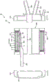
Fig. 7 is a longitudinal sectional view sequentially showing a process of manufacturing the artificial lung shown in fig. 1.
Fig. 8 is a longitudinal sectional view sequentially showing a process of manufacturing the artificial lung shown in fig. 1.
Fig. 9 is a longitudinal sectional view sequentially showing a process of manufacturing the artificial lung shown in fig. 1.
Fig. 10 is a longitudinal sectional view sequentially showing a process of manufacturing the artificial lung shown in fig. 1.
Fig. 11 is a longitudinal sectional view sequentially showing a process of manufacturing the artificial lung shown in fig. 1.
Fig. 12 is a longitudinal sectional view sequentially showing a process of manufacturing the artificial lung shown in fig. 1.
Fig. 13 is a longitudinal sectional view sequentially showing a process of manufacturing the artificial lung shown in fig. 1.
Fig. 14 is a longitudinal sectional view sequentially showing a process of manufacturing the artificial lung shown in fig. 1.
Fig. 15 is a vertical sectional view sequentially showing a process of manufacturing an artificial lung in which the hollow fiber type blood treatment device of the present invention is applied to the artificial lung.
Fig. 16 is a vertical sectional view sequentially showing a process of manufacturing an artificial lung in which the hollow fiber type blood treatment device of the present invention is applied to the artificial lung.
Fig. 17 is a vertical sectional view sequentially showing a process of manufacturing an artificial lung in which the hollow fiber type blood treatment device of the present invention is applied to the artificial lung.
Fig. 18 is a vertical sectional view sequentially showing a process of manufacturing an artificial lung in which the hollow fiber type blood treatment device of the present invention is applied to the artificial lung.
Detailed Description
Hereinafter, a method for manufacturing a hollow fiber type blood treatment device and a hollow fiber type blood treatment device according to the present invention will be described in detail based on preferred embodiments shown in the drawings.
< embodiment 1 >
Fig. 1 is a plan view showing an embodiment in which the hollow fiber type blood treatment device of the present invention is applied to an artificial lung. Fig. 2 is a view of the artificial lung shown in fig. 1 as viewed from the direction of arrow a. Fig. 3 is a sectional view taken along line B-B of fig. 2. Fig. 4 is a view seen from the direction of arrow C in fig. 2. Fig. 5 is a cross-sectional view taken along line D-D of fig. 1. Fig. 6 is a sectional view taken along line E-E of fig. 5. Fig. 7 to 14 are longitudinal sectional views each showing a process of manufacturing the artificial lung shown in fig. 1 (including the method of manufacturing the hollow fiber type blood processing apparatus of the present invention) in order. In fig. 1, 3, 4, and 14, the left side is referred to as "left" or "left (one)", and the right side is referred to as "right" or "right (the other)". In fig. 7 to 13 (the same applies to fig. 15 to 18), the upper side is referred to as "upper" or "upper", and the lower side is referred to as "lower" or "lower". In fig. 1 to 6, the inside of the artificial lung is referred to as "blood inflow side" or "upstream side", and the outside is referred to as "blood outflow side" or "downstream side".
The artificial lung 10 shown in fig. 1 to 5 has a substantially cylindrical overall shape. The artificial lung 10 is an artificial lung with a heat exchanger, and includes a heat exchange portion 10B provided inside and performing heat exchange with blood, and an artificial lung 10A as a gas exchange portion provided on the outer peripheral side of the heat exchange portion 10B and performing gas exchange with blood. The artificial lung 10 may be used, for example, in a blood extracorporeal circuit.
The artificial lung 10 has a casing 2A, and the artificial lung 10A and the heat exchange portion 10B are housed in the casing 2A.
The housing 2A includes a cylindrical housing body 21A, a plate-like first lid 22A for sealing the left end opening of the cylindrical housing body 21A, and a plate-like second lid 23A for sealing the right end opening of the cylindrical housing body 21A.
The cylindrical case body 21A, the first lid 22A, and the second lid 23A are made of a resin material. The first lid 22A and the second lid 23A are fixed to the cylindrical case main body 21A by welding, bonding with an adhesive, or the like.
A tubular blood outflow hole 28 is formed in the outer peripheral portion of the cylindrical housing main body 21A. The blood outflow hole 28 protrudes in a substantially tangential direction of the outer peripheral surface of the cylindrical housing main body 21A (see fig. 5).
A tubular cleaning hole 205 is formed in an outer peripheral portion of the cylindrical housing body 21A in a protruding manner. The cleaning hole 205 is formed in the outer peripheral portion of the cylindrical shell body 21A so that the central axis thereof intersects the central axis of the cylindrical shell body 21A.
A tubular gas outlet hole 27 is formed in the first lid 22A in a protruding manner. The gas outflow hole 27 is formed in the outer peripheral portion of the first lid 22A so that the center axis thereof intersects the center of the first lid 22A (see fig. 2).
Further, the blood inlet hole 201 protrudes from the end surface of the first cover 22A such that the center axis thereof is eccentric with respect to the center of the first cover 22A.
The second lid 23A has tubular gas inlet holes 26, heat medium inlet holes 202, and heat medium outlet holes 203 formed therein in a protruding manner. The gas inlet hole 26 is formed in the edge portion of the end surface of the second cover 23A. The heat medium inlet hole 202 and the heat medium outlet hole 203 are formed in substantially the center of the end surface of the second cover 23A. The center lines of the heat medium inlet hole 202 and the heat medium outlet hole 203 are slightly inclined with respect to the center line of the second lid 23A.
In the present invention, the overall shape of the housing 2A is not necessarily formed in a complete cylindrical shape, and may be, for example, a shape partially lacking or a shape with an added irregular portion.
As shown in fig. 3 and 5, an artificial lung 10A having a cylindrical shape along an inner peripheral surface thereof is housed in the housing 2A. The artificial lung 10A is composed of a cylindrical hollow fiber membrane bundle (outer hollow fiber membrane bundle) 3A and a filter member (outer sheet member) 41A as the bubble removing means 4A provided on the outer peripheral side of the hollow fiber membrane bundle 3A. The hollow fiber membrane bundle 3A and the filter member 41A are arranged in this order from the blood inflow side, i.e., the hollow fiber membrane bundle 3A and the filter member 41A.
Further, a heat exchange portion 10B that is cylindrical along an inner peripheral surface thereof (i.e., concentrically arranged) is provided inside the artificial lung 10A. The heat exchange unit 10B includes a cylindrical hollow fiber membrane bundle (inner hollow fiber membrane bundle) 3B and an intermediate sheet member (inner sheet member) 11 provided on the outer peripheral side of the hollow fiber membrane bundle 3B. The hollow fiber membrane bundle 3B and the intermediate sheet member 11 are arranged in this order from the blood inflow side as the hollow fiber membrane bundle 3B and the hollow fiber membrane bundle 3B.
As shown in fig. 6, each of the hollow fiber membrane bundles 3A and 3B is composed of a plurality of hollow fiber membranes 31, and the hollow fiber membranes 31 are bundled, that is, stacked in layers. The number of layers is not particularly limited, and is preferably 3 to 40 layers, for example. Each of the hollow fiber membranes 31 of the hollow fiber membrane bundle 3A has a gas exchange function for exchanging gas. On the other hand, each hollow fiber membrane 31 of the hollow fiber membrane bundle 3B has a function of performing heat exchange.
As shown in fig. 3, both end portions of each of the hollow fiber membrane bundles 3A and 3B are collectively fixed to the inner surface of the cylindrical housing main body 21A by partition walls 8 and 9. The partitions 8 and 9 are made of potting material such as polyurethane and silicone rubber, or adhesive. Further, the inner peripheral portion of the hollow fiber membrane bundle 3B is engaged with the concave-convex portion 244 formed on the outer peripheral portion of the first cylindrical member 241. By this engagement and the fixation by the partition walls 8 and 9, the hollow fiber membrane bundle 3B is reliably fixed to the cylindrical housing main body 21A, and therefore, the occurrence of positional displacement of the hollow fiber membrane bundle 3B during use of the artificial lung 10 can be reliably prevented. The concave-convex portion 244 also functions as a channel for flowing the blood B around the entire hollow fiber membrane bundle 3B.
As shown in fig. 5, the maximum outer diameter of the hollow fiber membrane bundle 3A Preferably 20mm to 200mm, more preferably 40mm to 150 mm. Maximum outer diameter of hollow
 fiber membrane bundle 3B Preferably 10mm to 150mm, more preferably 20mm to 100 mm. As shown in fig. 3, the length L of the hollow
 fiber membrane bundle 3A and the length L in the central axis direction of the bundle 3A are preferably 30mm to 250mm, and more preferably 50mm to 200 mm. By having such conditions, the hollow fiber membrane bundle 3A becomes a hollow fiber membrane bundle having an excellent gas exchange function, and the hollow fiber membrane bundle 3B becomes a hollow fiber membrane bundle having an excellent heat exchange function.
A blood channel 33 through which blood B flows from the upper side to the lower side in fig. 6 is formed outside each hollow fiber membrane 31 between the partition wall 8 and the partition wall 9 in the housing 2A, that is, in a space between the hollow fiber membranes 31.
On the upstream side of the blood channel 33, a blood inflow side space 24A (see fig. 3 and 5) communicating with the blood inflow hole 201 is formed as a blood inflow part of the blood B flowing in from the blood inflow hole 201.
The blood inflow side space 24A is a space defined by a first cylindrical member 241 having a cylindrical shape and a plate piece 242, and the plate piece 242 is disposed inside the first cylindrical member 241 and is disposed to face a part of the inner peripheral portion thereof. The blood B having flowed into the blood inflow side space 24A can flow through the entire blood channel 33 via the plurality of side holes 243 formed in the first cylindrical member 241.
Further, a second cylindrical member 245 disposed concentrically with the first cylindrical member 241 is disposed inside the first cylindrical member 241. Then, as shown in fig. 3, the heat medium H such as water flowing in from the heat medium inlet 202 passes through the flow paths (hollow portions) 32 of the hollow fiber membranes 31 of the hollow fiber membrane bundle 3B positioned on the outer peripheral side of the first cylindrical member 241 and the inside of the second cylindrical member 245 in this order, and is discharged from the heat medium outlet 203. When the heat medium H passes through the channels 32 of the hollow fiber membranes 31, heat exchange (heating or cooling) is performed between the blood B in contact with the hollow fiber membranes 31 in the blood channel 33.
A filter member 41A is disposed downstream of the blood channel 33, and the filter member 41A has a function of trapping air bubbles present in the blood B flowing through the blood channel 33.
The filter member 41A is made of a sheet material, and is attached to the outer peripheral portion of the hollow fiber membrane bundle 3A so as to cover the entire hollow fiber membrane bundle 3A. Both end portions of the filter member 41A are also fixed to the case 2A by the partition walls 8 and 9, respectively (see fig. 3).
The inside of the filter member 41A is in close contact with the outer peripheral portion of the hollow fiber membrane bundle 3A (see fig. 3, 5, and 6). Thereby, even if bubbles are present in the blood flowing through the blood channel 33, the bubbles can be reliably captured by the filter member 41A (see fig. 6). The air bubbles trapped in filter member 41A are pushed into hollow fiber membranes 31 in the vicinity of filter member 41A by the blood flow, and as a result, are removed from blood channel 33.
Further, a cylindrical space is formed between the outer peripheral portion of the filter member 41A and the inner peripheral portion of the cylindrical case main body 21A, and this space forms a blood outflow side space 25A. The blood outflow space 25A and the blood outflow hole 28 communicating with the blood outflow space 25A constitute a blood outflow portion. The blood outflow portion has the blood outflow side space 25A, so that a space for the blood B having passed through the filter member 41A to flow toward the blood outflow hole 28 is secured, and the blood B can be smoothly discharged.
An intermediate sheet member 11 is disposed between the hollow fiber membrane bundle 3A and the hollow fiber membrane bundle 3B. The intermediate sheet member 11 is made of a sheet material body, and is attached to the outer peripheral portion of the hollow fiber membrane bundle 3B so as to cover the entire hollow fiber membrane bundle 3B. Like filter member 41A, both end portions of intermediate sheet member 11 are also fixed to partition walls 8 and 9, respectively, and thereby fixed to housing 2A (see fig. 3).
The inner side of the intermediate sheet member 11 is in close contact with the outer peripheral portion of the hollow fiber membrane bundle 3B (see fig. 3, 5, and 6). As described later, the intermediate sheet member 11 is mainly used to maintain the shape of the hollow fiber membrane bundle 3B during the manufacturing process of the artificial lung 10. Therefore, the intermediate sheet member 11 is in close contact with the hollow fiber membrane bundle 3B, and the shape of the hollow fiber membrane bundle 3B can be reliably maintained.
In the artificial lung 10, the filter member 41A and the intermediate sheet member 11 are each formed into a mesh shape by crossing warp and weft. Examples of such members include woven fabrics in which the warp and weft are woven into plain weave, and members in which the warp and weft are crossed in a lattice pattern (including a mesh).
The mesh size of the intermediate sheet member 11 is larger than that of the filter member 41A. As described above, since the intermediate sheet member 11 is a member for maintaining the shape of the hollow fiber membrane bundle 3B, it is preferable that the mesh of the intermediate sheet member 11 be set as large as possible so as not to obstruct the flow of blood B flowing from the hollow fiber membrane bundle 3B to the hollow fiber membrane bundle 3A.
On the other hand, the filter member 41A is configured to be able to reliably trap bubbles and to allow blood B to easily pass therethrough by reducing the mesh size.
The thickness of the filter member 41A and the intermediate sheet member 11 is, for example, preferably 0.03 to 0.8mm, more preferably 0.05 to 0.5 mm. This makes it possible to easily attach each member in the process of manufacturing the artificial lung 10 and to reliably exhibit the function of each member after the artificial lung 10 is manufactured.
Examples of the constituent materials (constituent materials of warp and weft) of the filter member 41A and the intermediate sheet member 11 include polyolefins such as polyamide, polyethylene, and polypropylene; polyesters such as polyethylene terephthalate and polybutylene terephthalate; polyamide, cellulose, polyurethane, aramid fiber, etc., and 1 or 2 or more of them may be used in combination (for example, the warp and weft are made into different compositions, etc.). In particular, from the viewpoint of excellent antithrombotic property and less clogging, it is preferable to use (include) any of polyethylene terephthalate, polyethylene, polypropylene, polyamide, and polyurethane as a constituent material.
The filter member 41A and the intermediate sheet member 11 preferably have hydrophilicity. That is, the filter member 41A and the intermediate sheet member 11 are preferably made of a material having hydrophilicity itself, or are preferably subjected to hydrophilization treatment (for example, plasma treatment or the like). This reduces the passage resistance of the blood B in each member.
As shown in fig. 3, an annular rib 291 protrudes from the inside of the first cover 22A. Further, a first chamber 221a hermetically sealed is defined by the first lid 22A, the rib 291, and the partition wall 8. The first chamber 221a is a gas outflow chamber through which the gas G flows out. The left end opening of each hollow fiber membrane 31 (flow channel 32) of the hollow fiber membrane bundle 3A is open to the first chamber 221a, and communicates with the first chamber 221 a. Thereby, the gas G flowing through each hollow fiber membrane 31 flows out to the first chamber 221 a.
The gas outflow hole 27 communicates with the first chamber 221 a. A suction mechanism (not shown) for sucking the inside of the first chamber 221a is connected to the gas outflow hole (connection port) 27. The suction mechanism is not particularly limited, and examples thereof include wall-mounted suction. Wall-mounted suction is one of medical gas line devices for oxygen, therapeutic air, nitrogen, suction, and the like, and a connector of a line for suction provided on a wall or the like of an operating room can be connected to the gas outflow hole 27 for use. The pressure in the first chamber 221a can be reduced by the suction force generated by the operation of the suction mechanism, and therefore, the gas G can be reliably made to flow into the first chamber 221 a.
On the other hand, an annular rib 292 is also formed to protrude inside the second cover 23A. Further, the second chamber 231a is defined by the second cover 23A, the rib 292, and the partition wall 9. The second chamber 231a is a gas inflow chamber into which the gas G flows. The right end opening of each hollow fiber membrane 31 of the hollow fiber membrane bundle 3A is open to the second chamber 231a and communicates with the second chamber 231 a. Thereby, the gas G can be distributed from the second chamber 231a into each hollow fiber membrane 31.
In the artificial lung 10, the gas outflow hole 27 and the first chamber 221a constitute a gas outflow portion, and the gas outflow portion is disposed on the left end side (the other end side) of the hollow fiber membrane bundle 3A. The gas inlet hole 26 and the second chamber 231a constitute a gas inlet portion, and the gas inlet portion is disposed on the right end side (one end side) of the hollow fiber membrane bundle 3A. As described above, the lumen of each hollow fiber membrane 31 is defined as the flow channel 32 (gas flow channel), and the gas inlet portion and the gas outlet portion in the artificial lung 10 are provided on the upstream side and the downstream side of the flow channel 32, respectively. This makes the flow of the gas G linear, and therefore, the gas G can flow rapidly.
As described above, each of the hollow fiber membrane bundles 3A and 3B is composed of a plurality of hollow fiber membranes 31. The hollow fiber membrane bundle 3A will be representatively described below because the hollow fiber membrane bundle 3A and the hollow fiber membrane bundle 3B have the same hollow fiber membranes 31 except that the hollow fiber membrane bundle 3A is porous and has different applications.
Inner diameter of hollow fiber membrane 31 Preferably 50 μm to 700 μm, more preferably 70 μm to 600 μm (see FIG. 6). Outer diameter of
 hollow fiber membrane 31 Preferably 100 to 1000 μm, more preferably 120 to 800 μm (see FIG. 6). Further, the inner diameter
 And outer diameter
 Ratio of d1/d2Preferably 0.5 to 0.9, more preferably 0.6 to 0.8. Each
 hollow fiber membrane 31 having such conditions can reduce the pressure loss when the gas G flows through the flow path 32, which is the hollow portion of the hollow fiber membrane 31, while maintaining its own strength, and also contribute to maintaining the wound state of the hollow fiber membrane 31. E.g. inner diameter If the thickness is larger than the upper limit, the thickness of the
 hollow fiber membrane 31 becomes thin, and the strength is lowered by other conditions. In addition, the inside diameter If the pressure loss is less than the lower limit value, the pressure loss when the gas G flows through the
 hollow fiber membranes 31 increases due to other conditions.
Further, the distance between adjacent hollow fiber membranes 31 is more preferably set 1/10-1/1.
The method for producing such a hollow fiber membrane 31 is not particularly limited, and examples thereof include a method using extrusion molding, particularly a method using a drawing method or a solid-liquid phase separation method. Can be manufactured to have a prescribed inner diameter by this method And outer diameter
 The
The hollow fiber membranes 31.
As the material constituting each hollow fiber membrane 31, for example, a hydrophobic polymer material such as polypropylene, polyethylene, polysulfone, polyacrylonitrile, polytetrafluoroethylene, polymethylpentene, or the like can be used, and a polyolefin resin is preferable, and polypropylene is more preferable. Selecting such a resin material contributes to maintaining the wound state of the hollow fiber membrane 31 and to reducing the cost at the time of manufacturing.
Here, the flow of blood B in the artificial lung 10 of the present embodiment will be described.
In the artificial lung 10, the blood B flowing in from the blood inlet 201 passes through the blood inlet side space 24A and the side holes 243 in this order and flows into the heat exchange portion 10B. In the heat exchange portion 10B, the blood B flows in the downstream direction through the blood channel 33, and contacts the surface of each hollow fiber membrane 31 of the heat exchange portion 10B to perform heat exchange (heating or cooling). The blood B heat-exchanged as described above flows into the artificial lung 10A.
Then, in the artificial lung 10A, the blood B flows further downstream in the blood flow path 33. On the other hand, the gas (gas containing oxygen) supplied from the gas inlet 26 is distributed from the second chamber 231a to the flow paths 32 of the hollow fiber membranes 31 of the artificial lung 10A, flows through the flow paths 32, is collected in the first chamber 221a, and is discharged from the gas outlet 27. The blood B flowing through the blood channel 33 contacts the surface of each hollow fiber membrane 31 of the artificial lung 10A, and exchanges gas with the gas G flowing through the channel 32, that is, performs oxygenation and carbon dioxide removal.
When bubbles are mixed into the blood B subjected to gas exchange, the bubbles are captured by the filter member 41A, and can be prevented from flowing to the downstream side of the filter member 41A.
The blood B from which the heat exchange, the gas exchange, and the bubble removal have been performed in this order flows out from the blood outflow hole 28.
Next, a method for manufacturing the artificial lung 10 will be described with reference to fig. 7 to 14. The manufacturing method has a first forming process, a first mounting process, a second forming process, a second mounting process, a fixing process, and an assembling process.
[1] First forming process
The first forming step is a step of forming the hollow fiber membrane bundle 3B in the inner member 206 having the first cylindrical member 241 and the second cylindrical member 245. This process may be performed using a known winding device, whereby the hollow fiber membranes 31 are wound into the concave-convex portions 244 of the first cylindrical member 241.
[2] First mounting step
The first mounting step is a step of mounting the intermediate sheet member 11 to the hollow fiber membrane bundle 3B.
As described above, the intermediate sheet member 11 is formed in a mesh shape. Therefore, the intermediate sheet member 11 is stretchable. As shown in fig. 7, the intermediate sheet member 11 is formed as a member formed in a tubular shape in advance. The inner diameter of the intermediate sheet member 11 when it is formed into a cylinder in a natural state where no external force is applied, that is, in a state before it is attached to the hollow fiber membrane bundle 3B Is larger than the maximum outer diameter of the hollow
 fiber membrane bundle 3B Is small. As the
 For example, it is preferable that
 91-99.9%, more preferably 91-95% or 96-99%. Further, the length L3 of the
 intermediate sheet member 11 in the central axis direction is preferably the same as or slightly smaller than the length L of the hollow fiber membrane bundle 3B.
First, before the intermediate sheet member 11 is attached to the hollow fiber membrane bundle 3B, the intermediate sheet member 11 is turned upside down in the front-back direction. Then, the lower end portion of the intermediate sheet member 11 is folded back inward as it is in this inverted state, and this folded-back portion 111 is fitted into the upper end portion of the hollow fiber membrane bundle 3B (see fig. 7). The folded portion 111 returns to the original state in which the front and back surfaces are not turned over.
Next, as shown in fig. 8, the portion (the turning portion 112) positioned in the inverted state of the intermediate sheet member 11, that is, the portion located outside the folded portion 111 of the intermediate sheet member 11 is gradually slid downward, and the original state in which the front and back surfaces are not inverted is gradually returned.
Then, when this operation (operation) is continued, as shown in fig. 9, the intermediate sheet member 11 returns to the state in which the front and back are not turned over as a whole, and the mounting to the hollow fiber membrane bundle 3B is completed.
Further, as described above, the inner diameter of the intermediate sheet member 11 Is larger than the maximum outer diameter of the hollow
 fiber membrane bundle 3B Is small. Thus, in the process of mounting the
 intermediate sheet member 11, the intermediate sheet member 11 can fasten the hollow fiber membrane bundle 3B in the direction from the outer peripheral portion side toward the center axis side, and the fastened state is maintained even after the first mounting processHand (see arrow A of FIG. 5)11). As a result, the intermediate sheet member 11 can be reliably bonded to the hollow fiber membrane bundle 3B, and therefore, the shape of the hollow fiber membrane bundle 3B can be maintained, and the following steps can be performed easily and stably.
Further, in order to attach the intermediate sheet member 11 while fastening the hollow fiber membrane bundle 3B with the intermediate sheet member 11, a method of attaching the intermediate sheet member 11 so as to return from a state in which the front and back are turned upside down to its original state contributes to facilitating the operation of attaching the intermediate sheet member 11.
[3] Second forming process
The second forming process is a process of forming the hollow fiber membrane bundle 3A on the intermediate sheet member 11. This step can be performed by using a winding apparatus as in the first forming step. Thereby, the hollow fiber membranes 31 can be wound around the intermediate sheet member 11, and thus, as shown in fig. 10, a hollow fiber membrane bundle 3A is formed.
In addition, since the shape of the hollow fiber membrane bundle 3B is maintained by the intermediate sheet member 11, the winding of the hollow fiber membranes 31 can be stably performed.
[4] Second mounting step
The second mounting step is a step of mounting the filter member 41A to the hollow fiber membrane bundle 3A.
As described above, the filter member 41A is also formed in a mesh shape. Therefore, the filter member 41A is also extendable and retractable. As shown in fig. 11, the filter member 41A is formed as a member formed in a tubular shape in advance. The inner diameter of the filter member 41A when it is formed into a cylinder in a natural state without applying an external force Is larger than the maximum outer diameter of the hollow
 fiber membrane bundle 3A Is small. As the
 For example, it is preferable that
 90 to 96%, more preferably 91 to 95%, and still more preferably 92 to 95%. In addition, the length of the
 filter member 41A in the central axis direction is preferably the same as or slightly smaller than the length L of the hollow fiber membrane bundle 3A.
The attachment of filter member 41A to hollow fiber membrane bundle 3A in this step is the same as the attachment of intermediate sheet member 11 to hollow fiber membrane bundle 3A in the first attachment step. That is, before the filter member 41A is attached to the hollow fiber membrane bundle 3A, the filter member 41A is turned upside down after being turned inside out. Then, the strainer member 41A is attached so as not to return the inverted state to the original state in which the front and back are not inverted (see fig. 11). As a result, as shown in fig. 12, the filter member 41A returns to a state in which the front and back are not turned upside down as a whole, and the attachment to the hollow fiber membrane bundle 3A is completed.
Further, as described above, the inner diameter of the filter member 41A Is larger than the maximum outer diameter of the hollow
 fiber membrane bundle 3A Is small. In this way, during the attachment of the
 filter member 41A, the filter member 41A can fasten the hollow fiber membrane bundle 3A in the direction from the outer peripheral side thereof toward the central axis side, and the fastened state is maintained even after the second attachment step (see arrow a41A in fig. 5). This allows the filter member 41A to be reliably bonded to the hollow fiber membrane bundle 3A, and therefore, the bubble trapping function of the filter member 41A can be reliably exhibited.
The intermediate sheet member 11 fastens the hollow fiber membrane bundle 3B to a lesser extent than the filter member 41A fastens the hollow fiber membrane bundle 3A. This prevents excessive tightening of hollow-fiber membrane bundle 3B by filter member 41A, and therefore, it is possible to reliably prevent hollow-fiber membranes 31 and blood flow path 33 in hollow-fiber membrane bundle 3B from being blocked.
[5] Fixing procedure
The fixing step is a step of collectively fixing the hollow fiber membrane bundle 3A, the hollow fiber membrane bundle 3B, the filter member 41A, and the intermediate sheet member 11 to the first cylindrical member 241.
First, the materials constituting the partition walls 8 and 9 are applied to predetermined positions in a liquid state, and then cured. As a result, as shown in fig. 13, hollow fiber membrane bundle 3A, hollow fiber membrane bundle 3B, filter member 41A, and intermediate sheet member 11 are collectively fixed via partition wall 8 and partition wall 9.
[6] Assembling procedure
The assembly step is a step of assembling the inner member 206 to which the hollow fiber membrane bundle 3A, the hollow fiber membrane bundle 3B, the filter member 41A, and the intermediate sheet member 11 are fixed, with the cylindrical housing main body 21A, the first lid 22A, and the second lid 23A.
As shown in fig. 14, first, the inner member 206 is housed in the cylindrical case main body 21A. Next, the first cover 22A is attached and fixed from the right side, and the second cover 23A is attached and fixed from the left side. Thereby, the artificial lung 10 is completed.
The first mounting step and the second mounting step are preferably performed in an environment in which positrons are generated. This prevents static electricity from being generated when the filter member 41A and the intermediate sheet member 11 are attached.
< embodiment 2 >
Fig. 15 to 18 are longitudinal sectional views each showing in sequence a process of manufacturing an artificial lung in which the hollow fiber type blood treatment device of the present invention is applied to the artificial lung (including a method of manufacturing the hollow fiber type blood treatment device of the present invention).
Hereinafter, a method of manufacturing a hollow fiber type blood treatment device and a hollow fiber type blood treatment device according to embodiment 2 of the present invention will be described with reference to the drawings, and differences from the above-described embodiments will be mainly described, and descriptions of the same matters will be omitted.
This embodiment is the same as embodiment 1, except that a part of the method for manufacturing an artificial lung is different.
As shown in fig. 15 to 18, in the present embodiment, the peeling sheet 12 is used in the first mounting step. The peeling sheet 12 is in the form of a band, and the entire length thereof is sufficiently longer than the entire circumference of the outer periphery of the hollow fiber membrane bundle 3B. The length L4 of the peeling sheet 12 in the central axis direction of the hollow fiber membrane bundle 3B is sufficiently larger than the length of the hollow fiber membrane bundle 3B. The thickness of the peeling sheet 12 is preferably 0.05 to 0.2mm, and more preferably 0.1 to 0.13 mm.
Both surfaces of the peeling sheet 12 are subjected to friction reduction treatment for reducing friction. This makes it possible to easily perform a peeling operation (removal operation) described later. The friction reduction treatment is not particularly limited, and examples thereof include a method of applying Teflon coating ("Teflon" is a registered trademark). Thus, the peeling force in the peeling operation can be made to be, for example, less than 500mN/100 cm.
First, as shown in fig. 15, before the intermediate sheet member 11 is attached, the peeling sheet 12 is attached to the outer peripheral portion of the hollow fiber membrane bundle 3B so as to be wound around the entire circumferential range of the outer peripheral portion of the hollow fiber membrane bundle 3B. After this mounting, the support members 13 made of bent plate members are attached to the connection points of the both end portions of the peeling sheet 12. This prevents the peeling sheet 12 from being scattered and falling off from the hollow fiber membrane bundle 3B.
Next, as shown in fig. 16, the intermediate sheet member 11 is temporarily attached by being superposed on the peeling sheet 12. The mounting in this case may be performed in a state of being turned inside out as in the above-described embodiment 1, or may be performed in a state of being directly turned inside out without being turned inside out.
Next, as shown in fig. 17, the intermediate sheet member 11 is left in place, and the peeling sheet 12 is pulled upward. The peeling sheet 12 has a portion 121 that overflows above the intermediate sheet member 11 (see fig. 16). This allows the portion 121 to be pinched by the fingertips, thereby facilitating and ensuring the stretching operation.
Then, by performing this stretching operation, the peeling sheet 12 can be peeled (i.e., removed) as shown in fig. 18, and thus the intermediate sheet member 11 is attached to the hollow fiber membrane bundle 3B.
In the second mounting step, the filter member 41A may be similarly mounted on the hollow fiber membrane bundle 3A by using the separation sheet 12.
In the above, the method for manufacturing the hollow fiber type blood treatment device and the hollow fiber type blood treatment device of the present invention have been described with respect to the illustrated embodiments, but the present invention is not limited thereto, and each part constituting the hollow fiber type blood treatment device may be replaced with any component having a similar function. In addition, any structure may be added.
The method for manufacturing a hollow fiber type blood treatment device and the hollow fiber type blood treatment device according to the present invention may be combined with any 2 or more configurations (features) of the above-described embodiments.
In the above-described embodiment, the hollow fiber membranes of the hollow fiber membrane bundle constituting the artificial lung and the hollow fiber membranes of the hollow fiber membrane bundle constituting the heat exchange unit may be the same, but the present invention is not limited thereto, and for example, one (former) hollow fiber membrane may be thinner than the other (latter) hollow fiber membrane, or both hollow fiber membranes may be made of different materials.
In the above-described embodiment, the heat exchange portion is disposed on the inner side and the artificial lung is disposed on the outer side of the artificial lung and the heat exchange portion, but the present invention is not limited to this, and the artificial lung may be disposed on the inner side and the heat exchange portion may be disposed on the outer side. In this case, the blood flows from the outside to the inside.
In the above-described embodiment, the artificial lung and the heat exchange portion are made of a hollow fiber membrane bundle, that is, a resin material, but the present invention is not limited thereto, and a part or the whole of the heat exchange portion may be made of a metal material.
In the above embodiment, the hollow fiber membrane bundle of the artificial lung and the hollow fiber membrane bundle of the heat exchange portion are each formed in a cylindrical shape, but the invention is not limited thereto, and for example, the hollow fiber membrane bundle of the artificial lung may be formed in a cylindrical shape, and the hollow fiber membrane bundle of the heat exchange portion may be formed in a cylindrical shape.
The method for manufacturing a hollow fiber type blood treatment apparatus and the hollow fiber type blood treatment apparatus according to the present invention can be applied to artificial lungs, and can also be applied to dialyzers, for example.
Industrial applicability
The method for manufacturing a hollow fiber blood treatment device according to the present invention is a method for manufacturing a hollow fiber blood treatment device including a hollow fiber membrane bundle having a cylindrical or columnar outer shape formed by bundling a plurality of hollow fiber membranes and a sheet member attached to an outer peripheral portion of the hollow fiber membrane bundle, and the sheet member is attached to an outer peripheral portion of the hollow fiber membrane bundle, and includes an attaching step of attaching the sheet member to the outer peripheral portion of the hollow fiber membrane bundle, wherein the attaching step is performed in a state where the sheet member is formed in a cylindrical shape in advance. Therefore, the hollow fiber membrane bundle and the sheet member can be reliably adhered to each other. Therefore, the method for manufacturing a hollow fiber type blood processing apparatus of the present invention has industrial applicability.
Description of the reference numerals
10 Artificial lung
10A artificial lung
10B heat exchange part
2A outer casing
21A cylindrical case body
22A first cover body
221a first chamber
23A second cover body
231a second chamber
24A blood inflow side space
241 first cylindrical member
242 plate
243 side hole
244 concave-convex part
245 second cylindrical member
25A blood outflow side space
26 gas inflow hole
27 gas outflow hole
28 blood outflow hole
291. 292 Ribs
201 blood inflow hole
202 heat medium inflow hole
203 heat medium outflow hole
205 cleaning hole
206 medial member
3A hollow fiber membrane bundle (outer hollow fiber membrane bundle)
3B hollow fiber membrane bundle (inner hollow fiber membrane bundle)
31 hollow fiber membrane
32 flow path
33 blood flow path
4A bubble removing mechanism
41A filter member
8. 9 bulkhead
11 middle piece component (inner piece material)
111 folding part
112 turnover part
12 peeling sheet
13 support member
Arrows A11 and A41A
B blood
G gas
H heat medium


L, L3, L4 Length
Claims (10)
1. A method for manufacturing a hollow fiber blood treatment device having a hollow fiber membrane bundle and a sheet member attached to an outer peripheral portion of the hollow fiber membrane bundle, the hollow fiber membrane bundle having an outer shape formed in a cylindrical shape or a columnar shape by bundling a plurality of hollow fiber membranes, the method being characterized in that,
the manufacturing method comprises an attaching step of attaching the sheet member to the outer peripheral portion of the hollow fiber membrane bundle,
in the mounting step, the sheet body is turned over before the sheet body is mounted, and the sheet body is mounted while returning the turned-over state to an original state in which the sheet body is not turned over, and in the mounting step, the sheet body is mounted in a state in which the sheet body is previously formed into a tubular member.
2. The method of manufacturing a hollow fiber type blood treatment device according to claim 1, wherein the sheet member is stretchable and contractible, and has an inner diameter smaller than an outer diameter of the hollow fiber membrane bundle when the sheet member is formed into a cylinder in a natural state without applying an external force.
3. The method of manufacturing a hollow fiber type blood processing apparatus according to claim 2, wherein the sheet body is attached while the hollow fiber membrane bundle is fastened by the sheet body in a direction from an outer peripheral portion side thereof toward a central axis side thereof.
4. The method of manufacturing a hollow fiber type blood treatment device according to any one of claims 1 to 3, wherein in the mounting step, before the sheet member is mounted, a peeling sheet is mounted on the outer peripheral portion of the hollow fiber membrane bundle over the entire circumferential range of the outer peripheral portion of the hollow fiber membrane bundle, the sheet member is temporarily mounted by being superposed on the peeling sheet, and then the peeling sheet is removed while leaving the sheet member.
5. The method of manufacturing a hollow fiber type blood treatment apparatus according to claim 4, wherein a friction reduction treatment for reducing friction is performed on both surfaces of the peeling sheet.
6. The method of manufacturing a hollow fiber type blood treatment device according to any one of claims 1 to 3, wherein the sheet body is formed in a mesh shape that is stretchable freely.
7. A hollow fiber type blood treatment device comprising a hollow fiber membrane bundle having an outer shape formed in a cylindrical or columnar shape by bundling a plurality of hollow fiber membranes, and a sheet member attached to an outer peripheral portion of the hollow fiber membrane bundle,
the sheet body is attached in a state of being fastened in a direction from an outer peripheral portion side of the hollow fiber membrane bundle to a central axis side,
the hollow fiber membrane bundle includes an inner hollow fiber membrane bundle and an outer hollow fiber membrane bundle that are concentrically arranged,
the sheet body includes an inner sheet body attached to an outer peripheral portion of the inner hollow fiber membrane bundle and an outer sheet body attached to an outer peripheral portion of the outer hollow fiber membrane bundle,
the fastening degree of the inside sheet body with respect to the inside hollow fiber membrane bundle is lower than the fastening degree of the outside sheet body with respect to the outside hollow fiber membrane bundle.
8. The hollow fiber type blood treatment device according to claim 7, wherein the inner sheet body and the outer sheet body are each formed in a net shape,
the meshes of the inner sheet member are larger than the meshes of the outer sheet member.
9. The hollow fiber type blood treatment apparatus according to claim 7 or 8, wherein the hollow fiber membrane bundle is a hollow fiber membrane bundle in which blood passes between the hollow fiber membranes, and has a heat exchange function of exchanging heat with the blood.
10. The hollow fiber type blood processing device according to claim 9, which is an artificial lung.
Applications Claiming Priority (3)
| Application Number | Priority Date | Filing Date | Title |
|---|---|---|---|
| JP2015033811 | 2015-02-24 | ||
| JP2015-033811 | 2015-02-24 | ||
| PCT/JP2016/055183 WO2016136711A1 (en) | 2015-02-24 | 2016-02-23 | Method for manufacturing hollow-fiber-type blood processing device, and hollow-fiber-type blood processing device |
Publications (2)
| Publication Number | Publication Date |
|---|---|
| CN107249664A CN107249664A (en) | 2017-10-13 |
| CN107249664B true CN107249664B (en) | 2020-11-10 |
Family
ID=56788861
Family Applications (1)
| Application Number | Title | Priority Date | Filing Date |
|---|---|---|---|
| CN201680012299.XA Active CN107249664B (en) | 2015-02-24 | 2016-02-23 | Method for manufacturing hollow fiber type blood treatment device, and hollow fiber type blood treatment device |
Country Status (5)
| Country | Link |
|---|---|
| US (1) | US10807043B2 (en) |
| EP (1) | EP3263151B1 (en) |
| JP (1) | JP6757310B2 (en) |
| CN (1) | CN107249664B (en) |
| WO (1) | WO2016136711A1 (en) |
Families Citing this family (9)
| Publication number | Priority date | Publication date | Assignee | Title |
|---|---|---|---|---|
| WO2017051600A1 (en) * | 2015-09-25 | 2017-03-30 | テルモ株式会社 | Artificial lung |
| US10500529B2 (en) * | 2017-08-14 | 2019-12-10 | Stonehouse Water Technologies, LLC | Modular filter assembly |
| WO2019073279A1 (en) * | 2017-10-10 | 2019-04-18 | Sorin Group Italia S.R.L. | Blood processing unit (bpu) with countercurrent blood/water flow paths in the heat exchanger (hex) |
| WO2019150569A1 (en) * | 2018-02-05 | 2019-08-08 | テルモ株式会社 | Artificial lung and method for manufacturing same |
| EP4233934A3 (en) * | 2019-01-29 | 2023-10-04 | Nipro Corporation | Artificial lung device |
| EP3919095A4 (en) * | 2019-01-29 | 2023-01-25 | Nipro Corporation | Artificial lung device |
| EP4023270B1 (en) * | 2019-09-17 | 2023-12-27 | TERUMO Kabushiki Kaisha | Artificial lung |
| CN110559866A (en) * | 2019-09-26 | 2019-12-13 | 清华大学 | High-permeability compact hollow fiber membrane for blood oxygenation |
| US11724223B2 (en) | 2020-01-22 | 2023-08-15 | Stonehouse13Mfg., Llc | Systems and methods for forming modular filtration assemblies |
Citations (2)
| Publication number | Priority date | Publication date | Assignee | Title |
|---|---|---|---|---|
| JP2006280460A (en) * | 2005-03-31 | 2006-10-19 | Toray Ind Inc | Reformed base material |
| CN103491993A (en) * | 2011-03-31 | 2014-01-01 | 泰尔茂株式会社 | Artificial lung |
Family Cites Families (18)
| Publication number | Priority date | Publication date | Assignee | Title |
|---|---|---|---|---|
| JPS54126104A (en) * | 1978-03-20 | 1979-10-01 | Dainippon Printing Co Ltd | Method of making flat printing plate |
| US4415954A (en) * | 1982-04-23 | 1983-11-15 | Centurion Safety Products, Inc. | Grip shield |
| JPH08168525A (en) * | 1994-12-19 | 1996-07-02 | Terumo Corp | Production of hollow fiber membrane type blood treating device and production apparatus therefor |
| DE19782098T1 (en) * | 1996-11-15 | 1999-11-18 | Scitec K K | Hollow fiber type dialyzer |
| US6918886B1 (en) * | 1999-10-06 | 2005-07-19 | Membrana Gmbh | Membrane module for the hemodiafiltration with integrated pre- or postdilution of the blood |
| EP1344542B1 (en) * | 2002-03-14 | 2007-05-16 | Nipro Corporation | Dialyzer and method for manufacturing the same |
| EP1433490B1 (en) | 2002-12-26 | 2010-02-24 | Nipro Corporation | Dialyzer and method for manufacturing the same |
| JP4366268B2 (en) * | 2004-07-23 | 2009-11-18 | テルモ株式会社 | Artificial lung |
| JP4855119B2 (en) * | 2006-03-28 | 2012-01-18 | テルモ株式会社 | Filter member and artificial lung |
| ATE450914T1 (en) * | 2006-05-05 | 2009-12-15 | 3M Innovative Properties Co | TUBULAR CABLE CONNECTION |
| JP4883568B2 (en) * | 2006-08-31 | 2012-02-22 | 株式会社アデランス | Self hair utilization wig |
| JP4939280B2 (en) * | 2007-03-30 | 2012-05-23 | 本田技研工業株式会社 | Humidifier |
| JP5748197B2 (en) * | 2010-12-18 | 2015-07-15 | 岡田商事株式会社 | Vehicle cover |
| JP5781153B2 (en) | 2011-03-31 | 2015-09-16 | テルモ株式会社 | Artificial lung and extracorporeal circulation device |
| US10624664B2 (en) * | 2011-09-28 | 2020-04-21 | Evalve, Inc. | Apparatuses and methods for cutting a tissue bridge and/or removing a heart valve clip or suture |
| JP6396795B2 (en) | 2012-03-26 | 2018-09-26 | テルモ株式会社 | Manufacturing method of medical device |
| EP2832385B1 (en) * | 2012-03-26 | 2018-10-24 | Terumo Kabushiki Kaisha | Medical instrument |
| EP3206638A4 (en) * | 2014-10-16 | 2018-11-14 | Tang, John Ing Ching | Non-rolled adhesive condom and abbreviated condom |
-
2016
- 2016-02-23 WO PCT/JP2016/055183 patent/WO2016136711A1/en active Application Filing
- 2016-02-23 EP EP16755455.9A patent/EP3263151B1/en active Active
- 2016-02-23 JP JP2017502371A patent/JP6757310B2/en active Active
- 2016-02-23 CN CN201680012299.XA patent/CN107249664B/en active Active
-
2017
- 2017-08-23 US US15/684,018 patent/US10807043B2/en active Active
Patent Citations (2)
| Publication number | Priority date | Publication date | Assignee | Title |
|---|---|---|---|---|
| JP2006280460A (en) * | 2005-03-31 | 2006-10-19 | Toray Ind Inc | Reformed base material |
| CN103491993A (en) * | 2011-03-31 | 2014-01-01 | 泰尔茂株式会社 | Artificial lung |
Also Published As
| Publication number | Publication date |
|---|---|
| WO2016136711A1 (en) | 2016-09-01 |
| US20170348639A1 (en) | 2017-12-07 |
| CN107249664A (en) | 2017-10-13 |
| JPWO2016136711A1 (en) | 2017-11-30 |
| JP6757310B2 (en) | 2020-09-16 |
| US10807043B2 (en) | 2020-10-20 |
| EP3263151A4 (en) | 2018-10-17 |
| EP3263151A1 (en) | 2018-01-03 |
| EP3263151B1 (en) | 2020-03-25 |
Similar Documents
| Publication | Publication Date | Title |
|---|---|---|
| CN107249664B (en) | Method for manufacturing hollow fiber type blood treatment device, and hollow fiber type blood treatment device | |
| JP4855119B2 (en) | Filter member and artificial lung | |
| JP4533850B2 (en) | Artificial lung | |
| JP4500776B2 (en) | Artificial lung | |
| TW200404600A (en) | Hollow fiber membrane module, hollow fiber membrane module unit, membrane filtering device using the same, and operating method thereof | |
| JP6236669B2 (en) | Method for manufacturing a liquid processing apparatus | |
| US9050564B2 (en) | Filter module and system having spirally wound membrane filters, and method for the production thereof | |
| KR20180097512A (en) | Membrane elements and end members for membrane elements used therein | |
| JP4874088B2 (en) | Artificial lung | |
| CN110290856B (en) | Hollow fiber membrane module and filtration method | |
| US11534536B2 (en) | Heat exchanger and oxygenator | |
| JPH08942A (en) | Dehumidifying hollow fiber membrane model | |
| JPS6061018A (en) | Filtering apparatus | |
| JP6217370B2 (en) | Separation membrane module | |
| WO2015008327A1 (en) | Artificial lung | |
| JP4533851B2 (en) | Artificial lung | |
| JP7003685B2 (en) | Filtration module | |
| JP2024140243A (en) | Hollow fiber membrane module and method for manufacturing hollow fiber membrane module | |
| CN118382491A (en) | Degassing module and liquid degassing method | |
| JP2015186770A (en) | Membrane separation device and membrane separation method | |
| JP2005238053A (en) | Hollow fiber membrane module |
Legal Events
| Date | Code | Title | Description |
|---|---|---|---|
| PB01 | Publication | ||
| PB01 | Publication | ||
| SE01 | Entry into force of request for substantive examination | ||
| SE01 | Entry into force of request for substantive examination | ||
| GR01 | Patent grant | ||
| GR01 | Patent grant |