CN107106315B - Shape formable apparatus including locking tab - Google Patents
Shape formable apparatus including locking tab Download PDFInfo
- Publication number
- CN107106315B CN107106315B CN201580068460.0A CN201580068460A CN107106315B CN 107106315 B CN107106315 B CN 107106315B CN 201580068460 A CN201580068460 A CN 201580068460A CN 107106315 B CN107106315 B CN 107106315B
- Authority
- CN
- China
- Prior art keywords
- locking tab
- locking
- island
- tab
- state
- Prior art date
- Legal status (The legal status is an assumption and is not a legal conclusion. Google has not performed a legal analysis and makes no representation as to the accuracy of the status listed.)
- Active
Links
- 239000007787 solid Substances 0.000 claims abstract description 190
- 238000004891 communication Methods 0.000 claims abstract description 9
- 239000012530 fluid Substances 0.000 claims abstract description 9
- 239000000463 material Substances 0.000 claims description 109
- 238000005253 cladding Methods 0.000 claims description 74
- 229920003023 plastic Polymers 0.000 claims description 7
- 239000004033 plastic Substances 0.000 claims description 7
- 238000000034 method Methods 0.000 description 34
- 239000000758 substrate Substances 0.000 description 26
- 238000005452 bending Methods 0.000 description 18
- 238000007373 indentation Methods 0.000 description 16
- 230000033001 locomotion Effects 0.000 description 14
- 239000007789 gas Substances 0.000 description 11
- 238000012360 testing method Methods 0.000 description 11
- 230000008859 change Effects 0.000 description 10
- 230000008878 coupling Effects 0.000 description 10
- 238000010168 coupling process Methods 0.000 description 10
- 238000005859 coupling reaction Methods 0.000 description 10
- 230000002829 reductive effect Effects 0.000 description 10
- -1 triclosan) Chemical class 0.000 description 10
- 238000005259 measurement Methods 0.000 description 8
- 230000007423 decrease Effects 0.000 description 6
- 238000005516 engineering process Methods 0.000 description 6
- 239000000203 mixture Substances 0.000 description 6
- 230000036961 partial effect Effects 0.000 description 6
- 239000011248 coating agent Substances 0.000 description 5
- 238000000576 coating method Methods 0.000 description 5
- 230000001965 increasing effect Effects 0.000 description 5
- 230000008569 process Effects 0.000 description 5
- 230000037303 wrinkles Effects 0.000 description 5
- 229920004943 Delrin® Polymers 0.000 description 4
- 239000011230 binding agent Substances 0.000 description 4
- 229920001577 copolymer Polymers 0.000 description 4
- 239000002985 plastic film Substances 0.000 description 4
- 229920002635 polyurethane Polymers 0.000 description 4
- 239000004814 polyurethane Substances 0.000 description 4
- 238000010998 test method Methods 0.000 description 4
- 229910052782 aluminium Inorganic materials 0.000 description 3
- XAGFODPZIPBFFR-UHFFFAOYSA-N aluminium Chemical compound [Al] XAGFODPZIPBFFR-UHFFFAOYSA-N 0.000 description 3
- 239000004205 dimethyl polysiloxane Substances 0.000 description 3
- 238000004049 embossing Methods 0.000 description 3
- LYCAIKOWRPUZTN-UHFFFAOYSA-N ethylene glycol Natural products OCCO LYCAIKOWRPUZTN-UHFFFAOYSA-N 0.000 description 3
- 230000001747 exhibiting effect Effects 0.000 description 3
- 238000007667 floating Methods 0.000 description 3
- 238000005304 joining Methods 0.000 description 3
- 230000000670 limiting effect Effects 0.000 description 3
- 238000004519 manufacturing process Methods 0.000 description 3
- 239000000178 monomer Substances 0.000 description 3
- 238000000465 moulding Methods 0.000 description 3
- 229920000435 poly(dimethylsiloxane) Polymers 0.000 description 3
- 229920000139 polyethylene terephthalate Polymers 0.000 description 3
- 239000005020 polyethylene terephthalate Substances 0.000 description 3
- 230000000717 retained effect Effects 0.000 description 3
- 238000007789 sealing Methods 0.000 description 3
- MHAJPDPJQMAIIY-UHFFFAOYSA-N Hydrogen peroxide Chemical compound OO MHAJPDPJQMAIIY-UHFFFAOYSA-N 0.000 description 2
- 239000004944 Liquid Silicone Rubber Substances 0.000 description 2
- KFSLWBXXFJQRDL-UHFFFAOYSA-N Peracetic acid Chemical compound CC(=O)OO KFSLWBXXFJQRDL-UHFFFAOYSA-N 0.000 description 2
- 239000004698 Polyethylene Substances 0.000 description 2
- 229920000954 Polyglycolide Polymers 0.000 description 2
- 229910000831 Steel Inorganic materials 0.000 description 2
- 230000003213 activating effect Effects 0.000 description 2
- 230000008901 benefit Effects 0.000 description 2
- FACXGONDLDSNOE-UHFFFAOYSA-N buta-1,3-diene;styrene Chemical compound C=CC=C.C=CC1=CC=CC=C1.C=CC1=CC=CC=C1 FACXGONDLDSNOE-UHFFFAOYSA-N 0.000 description 2
- 239000002131 composite material Substances 0.000 description 2
- 238000005520 cutting process Methods 0.000 description 2
- 239000000645 desinfectant Substances 0.000 description 2
- 229920001971 elastomer Polymers 0.000 description 2
- 238000001125 extrusion Methods 0.000 description 2
- 230000005484 gravity Effects 0.000 description 2
- 229920001903 high density polyethylene Polymers 0.000 description 2
- 239000004700 high-density polyethylene Substances 0.000 description 2
- WGCNASOHLSPBMP-UHFFFAOYSA-N hydroxyacetaldehyde Natural products OCC=O WGCNASOHLSPBMP-UHFFFAOYSA-N 0.000 description 2
- 229920001684 low density polyethylene Polymers 0.000 description 2
- 239000004702 low-density polyethylene Substances 0.000 description 2
- 238000003754 machining Methods 0.000 description 2
- 229920001179 medium density polyethylene Polymers 0.000 description 2
- 239000004701 medium-density polyethylene Substances 0.000 description 2
- 229910052751 metal Inorganic materials 0.000 description 2
- 239000002184 metal Substances 0.000 description 2
- 238000012856 packing Methods 0.000 description 2
- 239000002245 particle Substances 0.000 description 2
- 229920006255 plastic film Polymers 0.000 description 2
- 229920000573 polyethylene Polymers 0.000 description 2
- 239000004633 polyglycolic acid Substances 0.000 description 2
- 239000004626 polylactic acid Substances 0.000 description 2
- 229920001155 polypropylene Polymers 0.000 description 2
- 229920001296 polysiloxane Polymers 0.000 description 2
- 230000002441 reversible effect Effects 0.000 description 2
- 229920002379 silicone rubber Polymers 0.000 description 2
- 239000002904 solvent Substances 0.000 description 2
- 239000010959 steel Substances 0.000 description 2
- 229920000468 styrene butadiene styrene block copolymer Polymers 0.000 description 2
- 238000001356 surgical procedure Methods 0.000 description 2
- 229920001187 thermosetting polymer Polymers 0.000 description 2
- XLYOFNOQVPJJNP-UHFFFAOYSA-N water Substances O XLYOFNOQVPJJNP-UHFFFAOYSA-N 0.000 description 2
- 238000003466 welding Methods 0.000 description 2
- RKDVKSZUMVYZHH-UHFFFAOYSA-N 1,4-dioxane-2,5-dione Chemical compound O=C1COC(=O)CO1 RKDVKSZUMVYZHH-UHFFFAOYSA-N 0.000 description 1
- GZMAAYIALGURDQ-UHFFFAOYSA-N 2-(2-hexoxyethoxy)ethanol Chemical compound CCCCCCOCCOCCO GZMAAYIALGURDQ-UHFFFAOYSA-N 0.000 description 1
- 238000010146 3D printing Methods 0.000 description 1
- 241000894006 Bacteria Species 0.000 description 1
- 0 C=*1C=*C*1 Chemical compound C=*1C=*C*1 0.000 description 1
- 229920000049 Carbon (fiber) Polymers 0.000 description 1
- 239000004593 Epoxy Substances 0.000 description 1
- JOYRKODLDBILNP-UHFFFAOYSA-N Ethyl urethane Chemical compound CCOC(N)=O JOYRKODLDBILNP-UHFFFAOYSA-N 0.000 description 1
- 229920010126 Linear Low Density Polyethylene (LLDPE) Polymers 0.000 description 1
- 229920000877 Melamine resin Polymers 0.000 description 1
- 239000004677 Nylon Substances 0.000 description 1
- 239000004952 Polyamide Substances 0.000 description 1
- 229920000331 Polyhydroxybutyrate Polymers 0.000 description 1
- 239000004743 Polypropylene Substances 0.000 description 1
- DBMJMQXJHONAFJ-UHFFFAOYSA-M Sodium laurylsulphate Chemical compound [Na+].CCCCCCCCCCCCOS([O-])(=O)=O DBMJMQXJHONAFJ-UHFFFAOYSA-M 0.000 description 1
- XEFQLINVKFYRCS-UHFFFAOYSA-N Triclosan Chemical compound OC1=CC(Cl)=CC=C1OC1=CC=C(Cl)C=C1Cl XEFQLINVKFYRCS-UHFFFAOYSA-N 0.000 description 1
- 230000002745 absorbent Effects 0.000 description 1
- 239000002250 absorbent Substances 0.000 description 1
- 238000009825 accumulation Methods 0.000 description 1
- 239000000853 adhesive Substances 0.000 description 1
- 230000001070 adhesive effect Effects 0.000 description 1
- 229920003232 aliphatic polyester Polymers 0.000 description 1
- 230000000845 anti-microbial effect Effects 0.000 description 1
- 239000004599 antimicrobial Substances 0.000 description 1
- 239000011324 bead Substances 0.000 description 1
- 229920002988 biodegradable polymer Polymers 0.000 description 1
- 239000004621 biodegradable polymer Substances 0.000 description 1
- 239000007844 bleaching agent Substances 0.000 description 1
- 238000004364 calculation method Methods 0.000 description 1
- 239000004917 carbon fiber Substances 0.000 description 1
- 239000001913 cellulose Substances 0.000 description 1
- 229920002678 cellulose Polymers 0.000 description 1
- 238000003486 chemical etching Methods 0.000 description 1
- 238000004140 cleaning Methods 0.000 description 1
- 238000010276 construction Methods 0.000 description 1
- 230000002596 correlated effect Effects 0.000 description 1
- 230000003247 decreasing effect Effects 0.000 description 1
- 238000013461 design Methods 0.000 description 1
- UMGXUWVIJIQANV-UHFFFAOYSA-M didecyl(dimethyl)azanium;bromide Chemical compound [Br-].CCCCCCCCCC[N+](C)(C)CCCCCCCCCC UMGXUWVIJIQANV-UHFFFAOYSA-M 0.000 description 1
- 239000012636 effector Substances 0.000 description 1
- 230000000694 effects Effects 0.000 description 1
- 239000000806 elastomer Substances 0.000 description 1
- 239000013536 elastomeric material Substances 0.000 description 1
- 230000002708 enhancing effect Effects 0.000 description 1
- 229920002313 fluoropolymer Polymers 0.000 description 1
- 238000000227 grinding Methods 0.000 description 1
- 125000004051 hexyl group Chemical group [H]C([H])([H])C([H])([H])C([H])([H])C([H])([H])C([H])([H])C([H])([H])* 0.000 description 1
- 229920001519 homopolymer Polymers 0.000 description 1
- 230000003993 interaction Effects 0.000 description 1
- 230000001788 irregular Effects 0.000 description 1
- 230000002427 irreversible effect Effects 0.000 description 1
- JJTUDXZGHPGLLC-UHFFFAOYSA-N lactide Chemical compound CC1OC(=O)C(C)OC1=O JJTUDXZGHPGLLC-UHFFFAOYSA-N 0.000 description 1
- 238000000608 laser ablation Methods 0.000 description 1
- 238000003698 laser cutting Methods 0.000 description 1
- 239000007788 liquid Substances 0.000 description 1
- 230000013011 mating Effects 0.000 description 1
- JDSHMPZPIAZGSV-UHFFFAOYSA-N melamine Chemical compound NC1=NC(N)=NC(N)=N1 JDSHMPZPIAZGSV-UHFFFAOYSA-N 0.000 description 1
- 150000002739 metals Chemical class 0.000 description 1
- VNWKTOKETHGBQD-UHFFFAOYSA-N methane Chemical compound C VNWKTOKETHGBQD-UHFFFAOYSA-N 0.000 description 1
- 244000005700 microbiome Species 0.000 description 1
- 229920001778 nylon Polymers 0.000 description 1
- 210000000056 organ Anatomy 0.000 description 1
- 230000008520 organization Effects 0.000 description 1
- 239000007800 oxidant agent Substances 0.000 description 1
- 238000004806 packaging method and process Methods 0.000 description 1
- 238000000059 patterning Methods 0.000 description 1
- 230000035699 permeability Effects 0.000 description 1
- ISWSIDIOOBJBQZ-UHFFFAOYSA-N phenol group Chemical group C1(=CC=CC=C1)O ISWSIDIOOBJBQZ-UHFFFAOYSA-N 0.000 description 1
- 150000002989 phenols Chemical class 0.000 description 1
- 238000000206 photolithography Methods 0.000 description 1
- 239000005015 poly(hydroxybutyrate) Substances 0.000 description 1
- 229920000747 poly(lactic acid) Polymers 0.000 description 1
- 229920000058 polyacrylate Polymers 0.000 description 1
- 229920002647 polyamide Polymers 0.000 description 1
- 229920001610 polycaprolactone Polymers 0.000 description 1
- 229920000728 polyester Polymers 0.000 description 1
- 229920005644 polyethylene terephthalate glycol copolymer Polymers 0.000 description 1
- 229920000642 polymer Polymers 0.000 description 1
- 229920000098 polyolefin Polymers 0.000 description 1
- 229920006324 polyoxymethylene Polymers 0.000 description 1
- 239000011148 porous material Substances 0.000 description 1
- 125000001453 quaternary ammonium group Chemical group 0.000 description 1
- 238000005096 rolling process Methods 0.000 description 1
- 239000005060 rubber Substances 0.000 description 1
- 238000005488 sandblasting Methods 0.000 description 1
- 235000019333 sodium laurylsulphate Nutrition 0.000 description 1
- 239000011343 solid material Substances 0.000 description 1
- 238000010561 standard procedure Methods 0.000 description 1
- 238000003860 storage Methods 0.000 description 1
- 239000000126 substance Substances 0.000 description 1
- KDYFGRWQOYBRFD-UHFFFAOYSA-N succinic acid Chemical compound OC(=O)CCC(O)=O KDYFGRWQOYBRFD-UHFFFAOYSA-N 0.000 description 1
- 239000004094 surface-active agent Substances 0.000 description 1
- 229920001897 terpolymer Polymers 0.000 description 1
- 229920001169 thermoplastic Polymers 0.000 description 1
- 229920002725 thermoplastic elastomer Polymers 0.000 description 1
- 239000012815 thermoplastic material Substances 0.000 description 1
- 239000004416 thermosoftening plastic Substances 0.000 description 1
- 229960003500 triclosan Drugs 0.000 description 1
- 238000007740 vapor deposition Methods 0.000 description 1
Images


Classifications
-
- A—HUMAN NECESSITIES
- A61—MEDICAL OR VETERINARY SCIENCE; HYGIENE
- A61F—FILTERS IMPLANTABLE INTO BLOOD VESSELS; PROSTHESES; DEVICES PROVIDING PATENCY TO, OR PREVENTING COLLAPSING OF, TUBULAR STRUCTURES OF THE BODY, e.g. STENTS; ORTHOPAEDIC, NURSING OR CONTRACEPTIVE DEVICES; FOMENTATION; TREATMENT OR PROTECTION OF EYES OR EARS; BANDAGES, DRESSINGS OR ABSORBENT PADS; FIRST-AID KITS
- A61F5/00—Orthopaedic methods or devices for non-surgical treatment of bones or joints; Nursing devices; Anti-rape devices
- A61F5/01—Orthopaedic devices, e.g. splints, casts or braces
- A61F5/04—Devices for stretching or reducing fractured limbs; Devices for distractions; Splints
- A61F5/05—Devices for stretching or reducing fractured limbs; Devices for distractions; Splints for immobilising
- A61F5/058—Splints
- A61F5/05833—Splints rigidified by vacuum evacuation
-
- B—PERFORMING OPERATIONS; TRANSPORTING
- B32—LAYERED PRODUCTS
- B32B—LAYERED PRODUCTS, i.e. PRODUCTS BUILT-UP OF STRATA OF FLAT OR NON-FLAT, e.g. CELLULAR OR HONEYCOMB, FORM
- B32B1/00—Layered products having a non-planar shape
-
- A—HUMAN NECESSITIES
- A61—MEDICAL OR VETERINARY SCIENCE; HYGIENE
- A61B—DIAGNOSIS; SURGERY; IDENTIFICATION
- A61B17/00—Surgical instruments, devices or methods, e.g. tourniquets
- A61B17/02—Surgical instruments, devices or methods, e.g. tourniquets for holding wounds open; Tractors
-
- A—HUMAN NECESSITIES
- A61—MEDICAL OR VETERINARY SCIENCE; HYGIENE
- A61F—FILTERS IMPLANTABLE INTO BLOOD VESSELS; PROSTHESES; DEVICES PROVIDING PATENCY TO, OR PREVENTING COLLAPSING OF, TUBULAR STRUCTURES OF THE BODY, e.g. STENTS; ORTHOPAEDIC, NURSING OR CONTRACEPTIVE DEVICES; FOMENTATION; TREATMENT OR PROTECTION OF EYES OR EARS; BANDAGES, DRESSINGS OR ABSORBENT PADS; FIRST-AID KITS
- A61F5/00—Orthopaedic methods or devices for non-surgical treatment of bones or joints; Nursing devices; Anti-rape devices
- A61F5/01—Orthopaedic devices, e.g. splints, casts or braces
-
- B—PERFORMING OPERATIONS; TRANSPORTING
- B65—CONVEYING; PACKING; STORING; HANDLING THIN OR FILAMENTARY MATERIAL
- B65B—MACHINES, APPARATUS OR DEVICES FOR, OR METHODS OF, PACKAGING ARTICLES OR MATERIALS; UNPACKING
- B65B11/00—Wrapping, e.g. partially or wholly enclosing, articles or quantities of material, in strips, sheets or blanks, of flexible material
- B65B11/50—Enclosing articles, or quantities of material, by disposing contents between two sheets, e.g. pocketed sheets, and securing their opposed free margins
-
- B—PERFORMING OPERATIONS; TRANSPORTING
- B65—CONVEYING; PACKING; STORING; HANDLING THIN OR FILAMENTARY MATERIAL
- B65B—MACHINES, APPARATUS OR DEVICES FOR, OR METHODS OF, PACKAGING ARTICLES OR MATERIALS; UNPACKING
- B65B17/00—Other machines, apparatus, or methods for packaging articles or materials
- B65B17/02—Joining articles, e.g. cans, directly to each other for convenience of storage, transport, or handling
- B65B17/025—Joining articles, e.g. cans, directly to each other for convenience of storage, transport, or handling the articles being joined by a top carrier element
-
- B—PERFORMING OPERATIONS; TRANSPORTING
- B65—CONVEYING; PACKING; STORING; HANDLING THIN OR FILAMENTARY MATERIAL
- B65D—CONTAINERS FOR STORAGE OR TRANSPORT OF ARTICLES OR MATERIALS, e.g. BAGS, BARRELS, BOTTLES, BOXES, CANS, CARTONS, CRATES, DRUMS, JARS, TANKS, HOPPERS, FORWARDING CONTAINERS; ACCESSORIES, CLOSURES, OR FITTINGS THEREFOR; PACKAGING ELEMENTS; PACKAGES
- B65D65/00—Wrappers or flexible covers; Packaging materials of special type or form
- B65D65/38—Packaging materials of special type or form
- B65D65/40—Applications of laminates for particular packaging purposes
- B65D65/403—Applications of laminates for particular packaging purposes with at least one corrugated layer
-
- B—PERFORMING OPERATIONS; TRANSPORTING
- B65—CONVEYING; PACKING; STORING; HANDLING THIN OR FILAMENTARY MATERIAL
- B65D—CONTAINERS FOR STORAGE OR TRANSPORT OF ARTICLES OR MATERIALS, e.g. BAGS, BARRELS, BOTTLES, BOXES, CANS, CARTONS, CRATES, DRUMS, JARS, TANKS, HOPPERS, FORWARDING CONTAINERS; ACCESSORIES, CLOSURES, OR FITTINGS THEREFOR; PACKAGING ELEMENTS; PACKAGES
- B65D65/00—Wrappers or flexible covers; Packaging materials of special type or form
- B65D65/38—Packaging materials of special type or form
- B65D65/40—Applications of laminates for particular packaging purposes
- B65D65/406—Applications of laminates for particular packaging purposes with at least one layer provided with a relief other than corrugations
-
- B—PERFORMING OPERATIONS; TRANSPORTING
- B65—CONVEYING; PACKING; STORING; HANDLING THIN OR FILAMENTARY MATERIAL
- B65D—CONTAINERS FOR STORAGE OR TRANSPORT OF ARTICLES OR MATERIALS, e.g. BAGS, BARRELS, BOTTLES, BOXES, CANS, CARTONS, CRATES, DRUMS, JARS, TANKS, HOPPERS, FORWARDING CONTAINERS; ACCESSORIES, CLOSURES, OR FITTINGS THEREFOR; PACKAGING ELEMENTS; PACKAGES
- B65D75/00—Packages comprising articles or materials partially or wholly enclosed in strips, sheets, blanks, tubes, or webs of flexible sheet material, e.g. in folded wrappers
- B65D75/002—Packages comprising articles or materials partially or wholly enclosed in strips, sheets, blanks, tubes, or webs of flexible sheet material, e.g. in folded wrappers in shrink films
-
- B—PERFORMING OPERATIONS; TRANSPORTING
- B65—CONVEYING; PACKING; STORING; HANDLING THIN OR FILAMENTARY MATERIAL
- B65D—CONTAINERS FOR STORAGE OR TRANSPORT OF ARTICLES OR MATERIALS, e.g. BAGS, BARRELS, BOTTLES, BOXES, CANS, CARTONS, CRATES, DRUMS, JARS, TANKS, HOPPERS, FORWARDING CONTAINERS; ACCESSORIES, CLOSURES, OR FITTINGS THEREFOR; PACKAGING ELEMENTS; PACKAGES
- B65D75/00—Packages comprising articles or materials partially or wholly enclosed in strips, sheets, blanks, tubes, or webs of flexible sheet material, e.g. in folded wrappers
- B65D75/006—Packages comprising articles or materials partially or wholly enclosed in strips, sheets, blanks, tubes, or webs of flexible sheet material, e.g. in folded wrappers in stretch films
-
- B—PERFORMING OPERATIONS; TRANSPORTING
- B65—CONVEYING; PACKING; STORING; HANDLING THIN OR FILAMENTARY MATERIAL
- B65D—CONTAINERS FOR STORAGE OR TRANSPORT OF ARTICLES OR MATERIALS, e.g. BAGS, BARRELS, BOTTLES, BOXES, CANS, CARTONS, CRATES, DRUMS, JARS, TANKS, HOPPERS, FORWARDING CONTAINERS; ACCESSORIES, CLOSURES, OR FITTINGS THEREFOR; PACKAGING ELEMENTS; PACKAGES
- B65D75/00—Packages comprising articles or materials partially or wholly enclosed in strips, sheets, blanks, tubes, or webs of flexible sheet material, e.g. in folded wrappers
- B65D75/04—Articles or materials wholly enclosed in single sheets or wrapper blanks
- B65D75/06—Articles or materials wholly enclosed in single sheets or wrapper blanks in sheets or blanks initially folded to form tubes
- B65D75/12—Articles or materials wholly enclosed in single sheets or wrapper blanks in sheets or blanks initially folded to form tubes with the ends of the tube closed by flattening and heat-sealing
-
- B—PERFORMING OPERATIONS; TRANSPORTING
- B65—CONVEYING; PACKING; STORING; HANDLING THIN OR FILAMENTARY MATERIAL
- B65D—CONTAINERS FOR STORAGE OR TRANSPORT OF ARTICLES OR MATERIALS, e.g. BAGS, BARRELS, BOTTLES, BOXES, CANS, CARTONS, CRATES, DRUMS, JARS, TANKS, HOPPERS, FORWARDING CONTAINERS; ACCESSORIES, CLOSURES, OR FITTINGS THEREFOR; PACKAGING ELEMENTS; PACKAGES
- B65D81/00—Containers, packaging elements, or packages, for contents presenting particular transport or storage problems, or adapted to be used for non-packaging purposes after removal of contents
- B65D81/02—Containers, packaging elements, or packages, for contents presenting particular transport or storage problems, or adapted to be used for non-packaging purposes after removal of contents specially adapted to protect contents from mechanical damage
- B65D81/05—Containers, packaging elements, or packages, for contents presenting particular transport or storage problems, or adapted to be used for non-packaging purposes after removal of contents specially adapted to protect contents from mechanical damage maintaining contents at spaced relation from package walls, or from other contents
- B65D81/127—Containers, packaging elements, or packages, for contents presenting particular transport or storage problems, or adapted to be used for non-packaging purposes after removal of contents specially adapted to protect contents from mechanical damage maintaining contents at spaced relation from package walls, or from other contents using rigid or semi-rigid sheets of shock-absorbing material
-
- F—MECHANICAL ENGINEERING; LIGHTING; HEATING; WEAPONS; BLASTING
- F16—ENGINEERING ELEMENTS AND UNITS; GENERAL MEASURES FOR PRODUCING AND MAINTAINING EFFECTIVE FUNCTIONING OF MACHINES OR INSTALLATIONS; THERMAL INSULATION IN GENERAL
- F16M—FRAMES, CASINGS OR BEDS OF ENGINES, MACHINES OR APPARATUS, NOT SPECIFIC TO ENGINES, MACHINES OR APPARATUS PROVIDED FOR ELSEWHERE; STANDS; SUPPORTS
- F16M13/00—Other supports for positioning apparatus or articles; Means for steadying hand-held apparatus or articles
-
- A—HUMAN NECESSITIES
- A61—MEDICAL OR VETERINARY SCIENCE; HYGIENE
- A61B—DIAGNOSIS; SURGERY; IDENTIFICATION
- A61B17/00—Surgical instruments, devices or methods, e.g. tourniquets
- A61B2017/00004—(bio)absorbable, (bio)resorbable or resorptive
-
- A—HUMAN NECESSITIES
- A61—MEDICAL OR VETERINARY SCIENCE; HYGIENE
- A61B—DIAGNOSIS; SURGERY; IDENTIFICATION
- A61B17/00—Surgical instruments, devices or methods, e.g. tourniquets
- A61B2017/00535—Surgical instruments, devices or methods, e.g. tourniquets pneumatically or hydraulically operated
- A61B2017/00561—Surgical instruments, devices or methods, e.g. tourniquets pneumatically or hydraulically operated creating a vacuum
- A61B2017/00566—Surgical instruments, devices or methods, e.g. tourniquets pneumatically or hydraulically operated creating a vacuum fixation of form upon application of vacuum
-
- A—HUMAN NECESSITIES
- A61—MEDICAL OR VETERINARY SCIENCE; HYGIENE
- A61B—DIAGNOSIS; SURGERY; IDENTIFICATION
- A61B17/00—Surgical instruments, devices or methods, e.g. tourniquets
- A61B2017/00831—Material properties
- A61B2017/00858—Material properties high friction or non-slip
-
- A—HUMAN NECESSITIES
- A61—MEDICAL OR VETERINARY SCIENCE; HYGIENE
- A61B—DIAGNOSIS; SURGERY; IDENTIFICATION
- A61B17/00—Surgical instruments, devices or methods, e.g. tourniquets
- A61B2017/00831—Material properties
- A61B2017/00862—Material properties elastic or resilient
-
- A—HUMAN NECESSITIES
- A61—MEDICAL OR VETERINARY SCIENCE; HYGIENE
- A61B—DIAGNOSIS; SURGERY; IDENTIFICATION
- A61B17/00—Surgical instruments, devices or methods, e.g. tourniquets
- A61B2017/00831—Material properties
- A61B2017/00889—Material properties antimicrobial, disinfectant
-
- A—HUMAN NECESSITIES
- A61—MEDICAL OR VETERINARY SCIENCE; HYGIENE
- A61B—DIAGNOSIS; SURGERY; IDENTIFICATION
- A61B17/00—Surgical instruments, devices or methods, e.g. tourniquets
- A61B2017/00831—Material properties
- A61B2017/00946—Material properties malleable
-
- A—HUMAN NECESSITIES
- A61—MEDICAL OR VETERINARY SCIENCE; HYGIENE
- A61B—DIAGNOSIS; SURGERY; IDENTIFICATION
- A61B17/00—Surgical instruments, devices or methods, e.g. tourniquets
- A61B2017/00831—Material properties
- A61B2017/00955—Material properties thermoplastic
-
- A—HUMAN NECESSITIES
- A61—MEDICAL OR VETERINARY SCIENCE; HYGIENE
- A61B—DIAGNOSIS; SURGERY; IDENTIFICATION
- A61B17/00—Surgical instruments, devices or methods, e.g. tourniquets
- A61B17/02—Surgical instruments, devices or methods, e.g. tourniquets for holding wounds open; Tractors
- A61B2017/0212—Cushions or pads, without holding arms, as tissue retainers, e.g. for retracting viscera
-
- A—HUMAN NECESSITIES
- A61—MEDICAL OR VETERINARY SCIENCE; HYGIENE
- A61B—DIAGNOSIS; SURGERY; IDENTIFICATION
- A61B90/00—Instruments, implements or accessories specially adapted for surgery or diagnosis and not covered by any of the groups A61B1/00 - A61B50/00, e.g. for luxation treatment or for protecting wound edges
- A61B90/08—Accessories or related features not otherwise provided for
- A61B2090/0801—Prevention of accidental cutting or pricking
-
- B—PERFORMING OPERATIONS; TRANSPORTING
- B65—CONVEYING; PACKING; STORING; HANDLING THIN OR FILAMENTARY MATERIAL
- B65D—CONTAINERS FOR STORAGE OR TRANSPORT OF ARTICLES OR MATERIALS, e.g. BAGS, BARRELS, BOTTLES, BOXES, CANS, CARTONS, CRATES, DRUMS, JARS, TANKS, HOPPERS, FORWARDING CONTAINERS; ACCESSORIES, CLOSURES, OR FITTINGS THEREFOR; PACKAGING ELEMENTS; PACKAGES
- B65D81/00—Containers, packaging elements, or packages, for contents presenting particular transport or storage problems, or adapted to be used for non-packaging purposes after removal of contents
- B65D81/18—Containers, packaging elements, or packages, for contents presenting particular transport or storage problems, or adapted to be used for non-packaging purposes after removal of contents providing specific environment for contents, e.g. temperature above or below ambient
- B65D81/20—Containers, packaging elements, or packages, for contents presenting particular transport or storage problems, or adapted to be used for non-packaging purposes after removal of contents providing specific environment for contents, e.g. temperature above or below ambient under vacuum or superatmospheric pressure, or in a special atmosphere, e.g. of inert gas
- B65D81/2007—Containers, packaging elements, or packages, for contents presenting particular transport or storage problems, or adapted to be used for non-packaging purposes after removal of contents providing specific environment for contents, e.g. temperature above or below ambient under vacuum or superatmospheric pressure, or in a special atmosphere, e.g. of inert gas under vacuum
- B65D81/2023—Containers, packaging elements, or packages, for contents presenting particular transport or storage problems, or adapted to be used for non-packaging purposes after removal of contents providing specific environment for contents, e.g. temperature above or below ambient under vacuum or superatmospheric pressure, or in a special atmosphere, e.g. of inert gas under vacuum in a flexible container
-
- B—PERFORMING OPERATIONS; TRANSPORTING
- B65—CONVEYING; PACKING; STORING; HANDLING THIN OR FILAMENTARY MATERIAL
- B65D—CONTAINERS FOR STORAGE OR TRANSPORT OF ARTICLES OR MATERIALS, e.g. BAGS, BARRELS, BOTTLES, BOXES, CANS, CARTONS, CRATES, DRUMS, JARS, TANKS, HOPPERS, FORWARDING CONTAINERS; ACCESSORIES, CLOSURES, OR FITTINGS THEREFOR; PACKAGING ELEMENTS; PACKAGES
- B65D81/00—Containers, packaging elements, or packages, for contents presenting particular transport or storage problems, or adapted to be used for non-packaging purposes after removal of contents
- B65D81/18—Containers, packaging elements, or packages, for contents presenting particular transport or storage problems, or adapted to be used for non-packaging purposes after removal of contents providing specific environment for contents, e.g. temperature above or below ambient
- B65D81/20—Containers, packaging elements, or packages, for contents presenting particular transport or storage problems, or adapted to be used for non-packaging purposes after removal of contents providing specific environment for contents, e.g. temperature above or below ambient under vacuum or superatmospheric pressure, or in a special atmosphere, e.g. of inert gas
- B65D81/2007—Containers, packaging elements, or packages, for contents presenting particular transport or storage problems, or adapted to be used for non-packaging purposes after removal of contents providing specific environment for contents, e.g. temperature above or below ambient under vacuum or superatmospheric pressure, or in a special atmosphere, e.g. of inert gas under vacuum
- B65D81/2038—Containers, packaging elements, or packages, for contents presenting particular transport or storage problems, or adapted to be used for non-packaging purposes after removal of contents providing specific environment for contents, e.g. temperature above or below ambient under vacuum or superatmospheric pressure, or in a special atmosphere, e.g. of inert gas under vacuum with means for establishing or improving vacuum
Landscapes
- Health & Medical Sciences (AREA)
- Engineering & Computer Science (AREA)
- Mechanical Engineering (AREA)
- Life Sciences & Earth Sciences (AREA)
- Public Health (AREA)
- Biomedical Technology (AREA)
- Animal Behavior & Ethology (AREA)
- General Health & Medical Sciences (AREA)
- Veterinary Medicine (AREA)
- Heart & Thoracic Surgery (AREA)
- Vascular Medicine (AREA)
- Orthopedic Medicine & Surgery (AREA)
- Nursing (AREA)
- Surgery (AREA)
- General Engineering & Computer Science (AREA)
- Nuclear Medicine, Radiotherapy & Molecular Imaging (AREA)
- Medical Informatics (AREA)
- Molecular Biology (AREA)
- Laminated Bodies (AREA)
- Blow-Moulding Or Thermoforming Of Plastics Or The Like (AREA)
- Invalid Beds And Related Equipment (AREA)
- Materials For Medical Uses (AREA)
Abstract
A shape formable apparatus including a locking tab is disclosed. The device may have a first state in which the device is formable and a second state in which the device has a desired shape and is substantially less formable than in the first state. The apparatus may further include: an envelope defining a chamber, a port positioned to couple the chamber in fluid communication with an environment; and at least two locking tabs positioned in the cavity in an at least partially overlapping configuration. Each locking sheet includes a major surface, and at least a portion of each locking sheet can be patterned to include solid regions and open regions, the solid regions being movable relative to each other within the major surface.
Description
Technical Field
The present disclosure relates generally to shape formable apparatuses that are configured to be formed into a desired shape and then retained in the desired shape, and in particular, to shape formable apparatuses that include a plurality of locking tabs.
Background
A variety of applications may benefit from materials or devices: which has a stiffness that can be changed from a first (flexible) state, in which the shape of the material can be shaped into a desired shape, to a second (more rigid) state, in which the desired shape can be retained or fixed.
Some existing shape-formable devices employ discrete particles (i.e., bulk media) that are generally free to move relative to each other in a gas-impermeable envelope, but these devices "card" together and resist relative motion when the internal pressure of the envelope is reduced below ambient pressure. This blockage of bulk media has been proposed for a variety of products, from medical restraints for infants (us patent No. 4,885,811), to limb retakes (us patent No. 4,657,003), to patient stability during surgery (us patent No. 6,308,353), to robotic end effectors (us publication No. 2010/0054903). One significant drawback of bulk media plugging is the significant volume required for a bulk media filled device. Bulk media is not well suited for thin sheet-like applications.
Other existing devices or systems employ a thin form factor change in bending stiffness. By placing a sheet of material in the envelope and removing air from the envelope (e.g., as described in U.S. publication No. 2012/0310126 and european et al, "jamSheets: thin interfaces with Tunable rigid Enabled by Layer Jamming", TEI' 14 meeting notes on the 8 th international meeting of tangible, embedded and materialized interactions, pages 65-72, computer Association (ACM), 2014 2 months), relatively thin articles with varying bending Stiffness can be achieved. Despite having a high young's modulus (or tensile modulus), they achieve a low bending stiffness in the non-seized state by allowing multiple thin layers of material to slide over each other. However, because these individual layers each have a high overall young's modulus, even in a non-seized state, and they are substantially continuous along one or more axes in-plane, they cannot readily extend within a major surface of a planar or thin article. Because the individual layers lack this ductility, the conformability of the layers is also limited. Therefore, these layers can take complex shapes only by producing wrinkles, and not by smoothly and continuously assuming arbitrary shapes. The bending stiffness of these systems can increase under vacuum because the multiple layers are stuck together and behave more like a single thick layer of high young's modulus material.
Disclosure of Invention
The present disclosure generally relates to a shape formable apparatus that includes an envelope defining a chamber and at least two locking tabs positioned in the chamber that can snap together to resist relative movement when pressure in the chamber is reduced below ambient pressure. The locking tabs are each patterned into solid and open areas in such a way: such that the solid regions are movable relative to one another in the major surfaces of the locking tabs, thereby allowing the locking tabs to extend within the major surfaces and thereby increasing the conformability of the locking tabs (i.e., along two or more axes). The solid regions may be discrete and separate from adjacent solid regions, and/or the solid regions may be connected to adjacent solid regions (e.g., continuous), such as by paths or bridges (e.g., long and/or tortuous paths) that allow relative movement between the solid regions within the major surfaces of the locking tabs. When the chamber is under vacuum, the locking tabs may snap together to increase the rigidity or stiffness (e.g., one or more of a bending stiffness (e.g., effective bending modulus), a tensile stiffness (e.g., effective tensile modulus), and an indentation stiffness (e.g., effective indentation modulus) of the device).
Some aspects of the present disclosure provide a shape formable apparatus having: a first state in which the device is formable so that the device can be formed into a desired shape; and a second state in which the device has a desired shape and is substantially less formable than in the first state. The apparatus may further include: an envelope defining a chamber, the envelope being formed of a gas-impermeable material; and a port positioned to couple the chamber in fluid communication with the environment. The apparatus may further include: at least two locking tabs positioned in the chamber in an at least partially overlapping configuration, wherein each locking tab includes a major surface, and wherein at least a portion of each locking tab is patterned to include solid areas and open areas, the solid areas being movable relative to each other within the major surfaces.
Other features and aspects of the disclosure will become apparent by reference to the detailed description and the accompanying drawings.
Drawings
FIG. 1 is a cutaway perspective view of a shape formable apparatus employing a locking tab comprising a continuous solid region according to one embodiment of the present disclosure.
Fig. 2A is a perspective view of a shape formable apparatus according to another embodiment of the disclosure, the apparatus shown in a first state.
FIG. 2B is a perspective view of the shape formable apparatus of FIG. 2A, the apparatus shown in a second state.
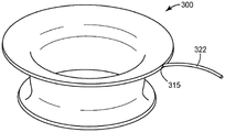
Fig. 3A is a perspective view of a shape formable apparatus according to another embodiment of the disclosure, the apparatus shown in a first state.
FIG. 3B is a perspective view of the shape formable apparatus of FIG. 3A, the apparatus shown in a second state.
FIG. 4 is a top plan view of the two locking tabs of FIG. 1, the two locking tabs shown in a staggered configuration.
FIG. 5 is a side cross-sectional view of the two locking tabs of FIG. 4, with the lower locking tab shown including a high friction surface.
6A-6C are schematic cross-sectional views of a shape formable apparatus employing a locking tab including a continuous solid region and a high friction surface according to another embodiment of the disclosure, illustrating a method of using the shape formable apparatus according to one embodiment of the disclosure.
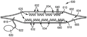
FIG. 7 is a cutaway perspective view of a shape formable apparatus employing a locking tab comprising discrete solid areas, according to another embodiment of the disclosure.
Figures 8A-8C are schematic cross-sectional views of a shape formable apparatus employing a locking tab including discrete solid areas and high friction surfaces according to another embodiment of the disclosure, illustrating a method of using the shape formable apparatus according to one embodiment of the disclosure.
Fig. 9A is a partial perspective view of a shape formable apparatus employing a locking tab including overlapping discrete solid areas according to another embodiment of the disclosure.
FIG. 9B is a schematic partial cross-sectional view of the shape formable apparatus of FIG. 9A.
Figure 10A is a perspective view of discrete solid regions of a locking tab according to one embodiment of the present disclosure.
Fig. 10B is a partial perspective view of a shape formable apparatus employing the discrete solid regions of fig. 10A overlapping along two axes according to another embodiment of the disclosure.
FIG. 10C is a partial cutaway perspective view of the shape formable apparatus of FIG. 10B taken along line 10C-10C.
FIG. 10D is a partially cut-away perspective view of the shape formable apparatus of FIG. 10B taken along line 10D-10D.
Fig. 11-25 are each top plan views of a locking tab including a continuous solid area according to another embodiment of the present disclosure.
Detailed Description
The present disclosure generally relates to a shape formable apparatus that includes an envelope defining an internal chamber and at least two overlapping locking tabs positioned in the chamber. Each locking tab may be patterned into solid areas and open areas (i.e., gaps or spaces between solid areas) such that at least some of the solid areas may move relative to each other within the major surface of the locking tab. The device has a first state in which the device is formable and capable of being changed into a desired three-dimensional shape. The device is further configured to change from a first state to a second state in which the three-dimensional shape of the device is substantially fixed or rigid (or at least much less formable than or much more rigid than in the first state) such that the shape can be maintained for a desired purpose. The device may change from the first state to the second state by: the chamber is evacuated to reduce the pressure in the chamber below ambient pressure and to remove gas (e.g., substantially all of the gas) from the chamber. The device may be changed from the second state to the first state by releasing the reduced pressure in the chamber and allowing it to return to ambient pressure. The apparatus may include an opening or port that provides fluid communication between the chamber and the environment, such that a vacuum source may be coupled to the port via a connector (e.g., tubing).
The shape-formable apparatus of the present disclosure may be used in a variety of applications that can benefit from a material or article that can change from a formable state, in which the apparatus can be formed into a desired shape, to a rigid or non-formable state, in which the desired shape can be substantially locked for a desired time. Examples of such applications include, but are not limited to: surgical portal constriction, tissue or organ constriction, patient positioning (e.g., maintaining a patient in a desired position during handling, treatment, surgery, etc.), packaging (e.g., holding, separating, and/or protecting items during transport), home and office storage, organization and/or display (e.g., modular shelving, drawer separators, etc.), fixtures (e.g., casts for securing limbs or joints), other suitable applications, or combinations thereof.
Methods of using shape formable devices, such as for tissue manipulation, are described in U.S. application No. 62/094279 filed on 12/19/2014 and 62/094336 filed on 12/19/2014, each of which is incorporated herein by reference in its entirety. Further, other shape formable apparatuses are described in U.S. application No. 62/094299 filed on 12/19/2014, which is incorporated herein by reference in its entirety.
As described above, unlike some existing shape formable apparatuses, the shape formable apparatus of the present disclosure occupies substantially less three-dimensional space or volume due to its substantially sheet or plate-like configuration. Some existing shape-formable devices are filled with beads or other particles or "bulk" substances or media. The sheet device of the present disclosure may overcome several disadvantages of existing "bulk" or non-sheet devices, including but not limited to: (i) bulk devices require significant three-dimensional size or space to conform to a desired shape (e.g., to cover or form around an object), have a nominally spherical shape factor and a relatively large cross-sectional area; (ii) bulk devices can only apply small forces to objects; (iii) the bulk device is strongest in terms of compressive force; and (iv) bulk devices do not easily conform to or take on a desired three-dimensional shape without applying significant force to the object.
Definition of
The terms "a", "an" and "the", "the" are used interchangeably with "at least one" to mean one or more of the element(s).
The term "and/or" means either or both. For example, "a and/or B" means a alone, B alone, or both a and B.
The terms "comprising," "including," or "having" and variations thereof are intended to cover the items listed thereafter and equivalents thereof as well as additional items.
Unless specified or limited otherwise, the term "coupled" and variations thereof are used broadly and encompass both direct and indirect couplings.
The terms "front," "back," "top," "bottom," and the like are used only to describe elements as they relate to one another, and are in no way intended to describe a particular orientation of the device, to indicate or imply a necessary or required orientation of the device, or to specify how the invention described herein will be used, mounted, displayed, or positioned in use.
"Low friction" surface may be used generally to refer to a surface having a low coefficient of dynamic friction. In some embodiments, the low friction surface may comprise a coefficient of dynamic friction of no greater than about 1, in some embodiments no greater than about 0.5, and in some embodiments no greater than about 0.25, sliding against another sheet of the same material according to ASTM D1894-08 for plastic films and sheets, when measured on flat films.
A "high friction" surface may be used to generally refer to a surface having a high coefficient of dynamic friction, such as when describing individual locking tabs, or to refer to relative movement between locking tabs when the device is in the first state. Such friction may be achieved by the properties of the surface material, or by the physical structure of the surface (e.g., 3M available from 3M company, st. paul, MN, st.) of st paul, MNTMClamping the material; the web address is www.3m.com/striping). In some embodiments, the high friction surface may comprise a dynamic coefficient of friction of at least about 1, in some embodiments at least about 3, and in some embodiments at least about 10, when measured on a flat film, sliding against another sheet of the same material according to ASTM D1894-08 for plastic films and sheets.
The phrases "tablet", "tabletThe terms "sheet-like configuration", "plate-like configuration" and variations thereof are used to describe articles having a small thickness relative to their length and width. The length and width of such an article may define a "major surface" of the article, but this major surface, and the article, need not be flat or planar. For example, the above phrases may be used to describe such articles: having a first ratio (R) of a thickness of a major surface (e.g., in a Z-direction orthogonal to the major surface of the article, at any point along the major surface) to a first surface dimension (e.g., width or length)1) And a second ratio (R) of the thickness of the main surface to the size of the second surface2) Wherein the first ratio (R)1) And a second ratio (R)2) Both less than 0.1. In some embodiments, the first ratio (R)1) And a second ratio (R)2) Can be less than 0.01; in some embodiments, less than 0.001; and in some embodiments, less than 0.0001. Note that the two surface dimensions need not be the same, and that the first ratio (R)1) And a second ratio (R)2) Need not be the same in order to have the first ratio (R)1) And a second ratio (R)2) Both falling within the desired range. Further, the first surface size, the second surface size, the thickness, the first ratio (R)1) And a second ratio (R)2) Need not be constant in order to have the first ratio (R)1) And a second ratio (R)2) Both falling within the desired range.
The phrase "major surface" is used to refer to the collective surface of the article (e.g., the outer surface of the article), even if the article is formed from smaller objects or portions. The smaller objects and portions may collectively define a major surface of the article. While such major surfaces may be planar in some cases, the major surfaces need not be flat or planar, and may be curved or otherwise complex in some cases. The phrase "major surface" is described in more detail below with respect to the locking tab 110 of fig. 1, 4, and 5.
The phrase "substantially parallel" is used to refer to at least two sheets or sheet-like articles having major surfaces, wherein the major surfaces of the sheets or articles are oriented parallel with respect to each other at any point along their respective major surfaces, but are allowed to deviate slightly from being parallel. For example, if two sheets have major surfaces that lie in an X-Y plane and are spaced apart by a distance in a Z direction that is orthogonal or perpendicular to the X-Y plane, the two sheets can be considered substantially parallel even if one or both of the two sheets have major surfaces that are oriented slightly out of orthogonal relationship with the Z direction at a given point or area along the major surfaces. In some embodiments, if one or both of the two sheets has a major surface that extends in the Z direction by an amount that is no greater than 10% of its dimension in the X-Y plane (i.e., has a Z dimension because the major surface is inclined relative to the Z direction), the two sheets can be substantially parallel; in some embodiments, no greater than 5%; in some embodiments, no greater than 2%; and in some embodiments, no greater than 1%. It is noted that the two sheets may be substantially parallel even if the two sheets are not flat or planar. For example, two curved sheets may be substantially parallel if the two sheets are curved to the same extent and in the same manner such that the orientation of the major surfaces of the two sheets with respect to the normal direction at any point or area along the major surfaces still falls within the above-described range.
The terms "polymer" and "polymeric material" refer to materials made from one monomer, such as a homopolymer, or to materials made from two or more monomers, such as a copolymer, terpolymer, or the like. The terms "copolymer" and "copolymeric material" refer to polymeric materials made from at least two monomers.
The terms "room temperature" and "ambient temperature" are used interchangeably to mean a temperature in the range of 20 ℃ to 25 ℃.
The term "effective tensile modulus" (ETM) as described in more detail below refers to the slope of a line in a plot of tension versus strain per unit width (elongation divided by original length), as tested according to the procedure described below in the examples section.
The term "effective flexural modulus" (EBM), described in more detail below, refers to the slope of a line in a plot of a dimensionless approximation of the tension per unit width versus deflection angle when a sample is stretched to induce bending according to the process described below in the examples section.
The term "effective indentation modulus" (EIM) refers to the slope of a line in a graph of applied force versus deflection distance when a sample is tested according to the procedure described below in the section of the examples referred to as effective indentation modulus.
Fig. 1 illustrates a shape formable apparatus 100 according to one embodiment of the disclosure. In contrast to the three-dimensional, high-volume configuration, the apparatus 100 is generally sheet-like or plate-like, or has a sheet-like or plate-like configuration.
As shown in fig. 1, the apparatus 100 may include: an envelope (or housing, or pouch) 102 defining an interior chamber 104; at least two adjacent locking tabs 110 positioned in the cavity 104 in an at least partially overlapping and substantially parallel configuration; and a port or opening 115 in the envelope 102 positioned to couple the chamber 104 in fluid communication with the environment, and the chamber 104 may be evacuated through the port or opening 115, for example, by coupling to a vacuum source 120.
For clarity, the top and bottom edges of the envelope 102 are shown in FIG. 1 as being substantially spaced apart (i.e., having sidewalls joining them). Similarly, the locking tabs 110 are shown as being substantially spaced apart from one another. However, it should be understood that this illustration is merely for a better and more clear illustration of how the locking tabs 110 may be stacked relative to one another and may be positioned in the chamber 104. In fact, the device 100 may appear flatter, having a sheet or plate-like configuration.
The apparatus 100 may be configured to be formed into and maintained in a desired shape. That is, the device 100 may have a first state in which the device 100 is formable (as described further below) such that the device 100 may be formed into a desired three-dimensional shape (e.g., exhibiting a non-zero gaussian curvature as described below). The device 100 may also have a second state in which the device 100 has a desired shape and is substantially rigid, or at least substantially more rigid than in the first state, and in which the desired shape is retained or locked (i.e., substantially non-formable).
Thus, the device 100 is formable, deformable, conformable, and/or manipulatable in a first state and substantially non-formable, non-deformable, non-conformable, and/or non-manipulatable in a second state. Terms such as formable, deformable, conformable, and/or manipulatable may be used when describing the ability of the device 100 to assume any desired shape in the first state, with the opposite term being true when the device 100 is in the second state.
To assume any desired three-dimensional shape and be "formable" (in a first state) according to the present disclosure, device 100 has both flexibility (or bendability) and ductility. For example, a solid sheet of high tensile modulus (e.g., young's modulus) material would not be considered "formable" in accordance with the present disclosure because, although it may bend, it cannot extend under a similar amount of force (e.g., under a reasonable amount of force, such as may be applied by hand). Generally, the apparatus can exhibit formability when the force required to achieve bending (whether manual or otherwise) is on a scale comparable to the force required to extend. For example, if a force of about 10-501b (45-224N) is required to cause the device to bend, a force of about 10-501b (45-224N) should be employed to cause the device to extend. A typical sample of material (simply modeled as a rectangular beam with thickness t, width w and length L supported only at both ends) will bend to maximum deflection (where L is the length of the beam and E is the Young's modulus). The same sample of material will be extended
 Giving the solid material a deltabend~δextThe only way of (a) is in the case of L-2 t, this is not a sheet or "sheet" according to the present disclosure.
For simplicity, the first state may be described as a state in which the device 100 is formable, or a state in which the shape (e.g., three-dimensional shape) of the device 100 may be changed or unlocked; and the second state may be described as a state in which the device 100 is "rigid" or a state in which the shape (e.g., three-dimensional shape) of the device 100 is fixed or locked.
The apparatus 100 may be changed to the second state by evacuating the chamber 104 (i.e., removing gas from the chamber 104) using the vacuum source 120. After the device 100 has been formed into its desired shape and changed from the first state to the second state, the port 115 (or connector 122 described below) may be sealed and/or disconnected from the vacuum source 120, and the device 100 may remain in the desired shape in the second state.
Fig. 2A-2B illustrate a shape formable apparatus 200 according to another embodiment of the disclosure, the apparatus 200 being sheet-like. The locking tabs (not shown) of the present disclosure are housed within a cavity defined by the cladding 202. The chamber (not shown) may be evacuated via the opening 215 and the connector 222, for example by connecting the connector 222 to a vacuum source (not shown). Fig. 2A shows the apparatus 200 in a first state in which the cavity within the cladding 202 and defined by the cladding 202 is not evacuated (i.e., not reduced to significantly below ambient pressure). While in the first state, the device 200 may be formed into a desired shape (i.e., a three-dimensional shape). Fig. 2B shows the device 200 after it has been formed into a desired shape and changed from a first state to a second state to "lock" (i.e., reversibly lock) the device 200 into the desired shape. The connector 222 is shown in fig. 2A and 2B as being integrally formed with the cladding 202 such that the connector 202 remains coupled to the cladding 202 in the second state (fig. 2B), but this is not necessarily so.
Similarly, fig. 3A-3B illustrate a shape formable apparatus 300 according to another embodiment of the disclosure, the apparatus 300 still being sheet-like, but having a tubular configuration. The locking tabs (not shown) of the present disclosure are housed within the cavity defined by the cladding 302 and may be oriented substantially parallel to the tubular surface of the cladding 302. The locking tabs may also be tubular, or one or more locking tabs may be positioned around the pipe elements (e.g., end-to-end or end-to-end). A single long locking tab may also be wrapped multiple times around itself to form many layers of a tubular shape. The envelope 302 may be evacuated via the opening 315 and the connector 322, for example by connecting the connector 322 to a vacuum source (not shown). Fig. 3A shows the apparatus 300 in a first state in which the cavity within the cladding 302 and defined by the cladding 302 is not evacuated (i.e., not reduced to significantly below ambient pressure). When in the first state, the device 300 may be formed into a desired shape (i.e., a three-dimensional shape). Fig. 3B shows the device 300 after it has been formed into a desired shape and changed from a first state to a second state to "lock" the device 300 into the desired shape. The connector 322 is shown in fig. 3A and 3B as being integrally formed with the cladding 302 such that the connector 302 is still coupled to the cladding 302 in the second state (fig. 3B), but this is not necessarily so.
The configuration of the apparatus 200 and 300 of fig. 2A-2B and 3A-3B, respectively, is shown by way of example only. Any additional details described herein with respect to other embodiments of the shape-formable apparatus of the present disclosure may also be applied to apparatuses 200 and 300, and vice versa.
Although not shown in fig. 2A-3B, in some embodiments, the devices of the present disclosure may have at least a slightly reduced volume when in the second state as compared to the first state. That is, in some embodiments, a device of the present disclosure in a second state can be at least partially folded relative to the first state. In the sheet-like device of the present disclosure, the collapse may occur primarily in the direction of the thickness of the device (i.e., the Z-direction), which in the first state is already small relative to the surface dimensions (i.e., the dimensions defining the major surfaces of the device).
The envelope 102 is substantially formed of a gas impermeable material. The envelope 102, or at least a portion thereof (e.g., at least a portion of an outer surface thereof), may be formed from a variety of materials, depending on the intended use of the device 100. Examples of suitable cladding materials include, but are not limited to: a composite material, a polymeric material (e.g., an elastomer, a thermoplastic, a thermoset, a biodegradable, or a combination thereof), or a combination thereof. In some embodiments, the envelope 102 or a portion thereof (e.g., at least a portion of an outer surface thereof) may be formed of an impermeable (e.g., liquid and air impermeable), non-absorbent, microporous, and/or non-porous material that is resistant to harboring bacteria and other insults. Thus, the envelope 102 or respective portions thereof may be easily cleaned and/or sterilized. Further, in some embodiments, the coating 102 or a portion thereof may include an antimicrobial layer or coating to inhibit the accumulation and/or growth of microorganisms on the coating 102. In some embodiments, the envelope 102 may be formed of materials compatible with common disinfectants and cleaners, such as oxidizing agents (e.g., bleach, hydrogen peroxide, dilute peracetic acid, etc.), quaternary ammonium disinfectants (e.g., dimethyl didecyl ammonium bromide), phenolic compounds (e.g., triclosan), cleaning surfactants (e.g., sodium lauryl sulfate), and solvents (e.g., glycol ethers, such as hexyl cellulose solvent or hexyl carbitol).
In some embodiments, the covering 102 may be formed of an elastomeric material that is highly extensible and conformable such that the overall extensibility or conformability of the device 100 is not limited by the covering 102. In other words, the malleability and conformability of the covering 102 is at least that of one locking tab 110, or at least that of a plurality of locking tabs 110. More specifically, in some embodiments, the cladding 102 can have a tensile modulus (e.g., young's modulus or an effective tensile modulus as set forth in the examples), a flexural modulus (e.g., an effective flexural modulus as set forth in the examples), and/or an indentation modulus (e.g., an effective indentation modulus as set forth in the examples) that is less than one locking tab 110 or less than a plurality of locking tabs 110.
In some embodiments, the cladding 102 can exhibit no greater than 5N/mm (e.g., as tested according to the test methods described in the examples section); in some embodiments, no greater than 3N/mm; in some embodiments, no greater than 1.5N/mm; in some embodiments, no greater than 1N/mm; in some embodiments, no greater than 0.5N/mm; and in some embodiments, an effective tensile modulus of no greater than 0.1N/mm. The cladding used in the following examples was tested by itself and found to have an effective tensile modulus of 1.21N/mm according to the method described in the "test procedures" section of the examples.
Examples of elastomeric materials may include silicone, Polydimethylsiloxane (PDMS), liquid silicone rubber, poly (styrene-butadiene-styrene), other suitable thermoplastic elastomers, and combinations thereof.
Examples of thermoplastic materials can include one or more of polyolefins (e.g., polyethylene (high density polyethylene (HDPE), Medium Density Polyethylene (MDPE), Low Density Polyethylene (LDPE), Linear Low Density Polyethylene (LLDPE)), metallic polyethylene, and the like, and combinations thereof), polypropylene (e.g., atactic and syndiotactic polypropylene)), polyamides (e.g., nylon), polyurethanes, polyacetals (such as Delrin), polyacrylates and polyesters (such as polyethylene terephthalate (PET), polyethylene terephthalate glycol (PETG), and aliphatic polyesters such as polylactic acid), fluoroplastics (such as THV available from 3M company (3M company, st. paul, MN), santa clara, MN), and combinations thereof.
Examples of thermoset materials may include one or more of polyurethane, silicone, epoxy, melamine, phenolic, and combinations thereof.
Examples of biodegradable polymers may include one or more of polylactic acid (PLA), polyglycolic acid (PGA), poly (caprolactone), copolymers of lactide and glycolide, poly (ethylene succinic acid), polyhydroxybutyrate, and combinations thereof.
In embodiments employing a polymeric cladding 102, the cladding 102 may be formed by a variety of methods, including relatively easy manufacturing methods, such as extrusion, molding, or combinations thereof.
In some embodiments, one or more surfaces of the cladding 102 (e.g., an outer surface thereof), or a portion thereof, can include a low-friction surface, which can be achieved by the material composition and/or texture of the respective surface, or by treating the surface (e.g., using a coating or by coupling a low-friction layer to a desired portion of the cladding 102, etc.).
In some embodiments, the apparatus 100 may be in the first state when the internal pressure within the chamber 104 is equal to ambient pressure (e.g., about 101kPa at sea level) or within +/-5% of ambient pressure. However, the chamber 104 may be at least partially evacuated (e.g., by coupling the port 115 to the vacuum source 120 and evacuating the chamber 104, i.e., removing gas from the chamber 104) to change the apparatus 100 to a second state in which the internal pressure within the chamber 104 is reduced below ambient pressure (e.g., greater than 5% below ambient pressure).
The vacuum source 120 is only schematically illustrated in fig. 1, but it should be understood that a variety of suitable vacuum sources may be coupled to the apparatus 100. For example, the vacuum source 120 may include one or more of, but is not limited to, a mechanical pump, a manual pump such as a syringe-plunger combination, other suitable vacuum sources that may reduce the pressure in the chamber 104, or a combination thereof.
Vacuum source 120 is shown by way of example only as being coupled to port 115 of apparatus 100 by connector 122. The connector 122 is shown by way of example as a pipe. In some embodiments, one or both of the connector 122 and the vacuum source 120 can be considered to form a portion of the apparatus 100 (e.g., the envelope 102 can be integrally formed with the connector 122 or include the connector 122); however, in some embodiments, the apparatus 100 may be considered to be coupled to one or both of the connector 122 and the vacuum source 120.
The lock tabs 110 are shown in figure 1 as forming a stack of lock tabs 110. For simplicity and by way of example only, the stack is shown as including four locking tabs 110. However, it should be understood that as few as two locking tabs and as many locking tabs as structurally possible may be employed in the apparatus of the present disclosure. Although the locking tabs 110 of fig. 1 are shown as separate tabs in a stack, it should be understood that "at least two locking tabs" generally refers to at least two overlapping sections or portions of a locking tab, and that these overlapping sections or portions need not actually be separate tabs, but instead may be sections or portions of one long locking tab that are stacked upon one another, such as by zig-zag the long locking tab, by rolling the locking tab, or by otherwise arranging the long locking tab such that it includes at least two overlapping portions or sections. For simplicity, this will be described herein and in the appended claims as "at least two locking tabs".
The number of locking tabs 110 may be selected to provide sufficient formability of the device 100 in the first state while also providing sufficient rigidity in the second state for a given application. In some embodiments, the number of locking tabs 110 employed may depend on the material composition and thickness of each locking tab 110.
The locking tab 110 of the present disclosure may be formed from a variety of materials depending on the desired application or use of the device 100. Examples of suitable locking sheet materials include, but are not limited to: paper materials; metals that can be annealed for enhanced forgeability (e.g., steel, aluminum); polymeric materials (e.g., ABS or delrin), composite materials (e.g., carbon fiber); other similar suitable materials and combinations thereof.
In some embodiments, the locking tabs 110 may all be formed of the same material; however, the locking tabs 110 employed in one device 100 need not all be formed of the same material. In some embodiments, some of the locking tabs 110 are formed of the same material, while other locking tabs 110 are formed of one or more different materials. In some embodiments, the locking tabs 110 may be arranged (e.g., stacked) in the chamber 104, such as in an alternating configuration, depending on the material composition. For example, in some embodiments, a locking tab 110 formed of a first material may be positioned adjacent to a locking tab 110 formed of a second material, the second material may be positioned adjacent to a locking tab 110 formed of the first material, and so on. However, in some embodiments, locking tabs 110 formed of different materials may be arranged in other configurations or even randomly in the chamber 104.
In some embodiments, the lock tabs 110 may all have the same thickness (i.e., in the Z direction orthogonal to the major surfaces of the lock tabs 110); however, in some embodiments, the locking tabs 110 employed in one device 100 need not all have the same thickness. In some embodiments, some of the locking tabs 110 may have the same thickness while other locking tabs 110 have one or more different thicknesses. In some embodiments, the locking tabs 110 may be arranged (e.g., stacked) in the chamber 104 according to thickness, e.g., in an order of increasing thickness, decreasing thickness, alternating thicknesses, another suitable configuration, or a combination thereof. However, in some embodiments, locking tabs 110 having different thicknesses may be randomly arranged in the chamber 104.
Further, in some embodiments, one or more of the locking tabs 110 can have a varying thickness such that the thickness is not constant throughout the locking tab 110.
In some embodiments, the locking tab 110 may be formed by a variety of methods, including but not limited to extrusion, molding, laser cutting, water jet, machining, stereolithography or other 3D printing, laser ablation, photolithography, chemical etching, rotary die cutting, embossing, other suitable negative or positive machining techniques, or combinations thereof.
When the device 100 is in the first state, the lock tabs 110 may be formable and slidable relative to each other, i.e., such that the major surfaces of adjacent lock tabs 110 slide past each other (e.g., in the X and Y directions) and may also move relative to each other in the Z direction orthogonal to any point along the major surfaces of the lock tabs 110. However, when the device 100 is in the second state (i.e., when the chamber 104 is evacuated), the locking tabs 110 may be substantially immovable or "locked" relative to each other in the surfaces (e.g., X and Y) and in the Z-direction such that the device 100 is "substantially/substantially immovable" or "substantially/substantially locked".
The "substantially/substantially immovable" or "substantially/substantially locked" apparatus 100 may also be referred to as "substantially rigid", "substantially more rigid than in the first state", or "substantially less formable than in the first state", and in some embodiments, may be characterized by a material property (e.g., a measure of stiffness, such as tensile modulus) of the apparatus 100 when the apparatus 100 is in the second (locked) state compared to the same material property of the apparatus 100 when the apparatus 100 is in the first (unlocked) state, as described in more detail below.
As further shown in fig. 1, at least a portion of each locking tab 110 may be patterned or segmented into solid areas 132 and open areas 134 (i.e., gaps or free spaces between the solid areas 132) such that at least some of the solid areas 132 are able to move relative to one another within the major surface S of the locking tab 110. For simplicity and clarity of illustration, the locking tab 110 of FIG. 1 is shown as having a solid profile; however, it should be understood that it is more likely that the edges of the locking tab 110 will not be continuously solid, but will instead be comprised of a solid area 132 and an open area 134 and possibly an incomplete portion of the solid area 132. For purposes of simplicity and clarity, one locking tab 110 will now be described in greater detail; however, it should be understood that the additional details described below may be applied to any locking tab 110 of the device 100.
By way of example only, the top (or bottom) surfaces of the individual solid areas 132 of the first locking tab 110 of fig. 4 collectively define one or more major surfaces of the locking tab 110. For simplicity, one exemplary major surface S is shown in fig. 1 and 4 as being substantially planar, but when the locking tab 110 is formed into a desired shape (e.g., by being formed on an object or conforming to a complex surface), the major surface S can take on any complex shape. Such complex shapes may be possible because solid regions 132 are able to move relative to each other within major surface S. That is, the shape of the major surface S may change (e.g., due to relative movement of the solid regions 132 defining the major surface S) and may be very complex. However, regardless of the shape of major surface S, solid regions 132 may move relative to each other within major surface S. Such movement may include bending relative to one another (e.g., deflecting into and out of major surface S, but in so doing also redefining major surface S) such that the resulting locking tab 110 is bendable, and also moving toward and away from one another such that the resulting locking tab 110 is malleable. This combination of flexibility (bendability) and ductility forms a formable locking tab 110.
While it should be understood that solid regions 132 also have a thickness in the Z-direction orthogonal to major surface S, there will be a major surface (e.g., major surface S) collectively defined by solid regions 132, and solid regions 132 will be able to move within that major surface. The solid regions 132 can also move relative to each other into and out of the major surface, or in the Z-direction relative to each other. However, a key distinguishing characteristic of the locking tabs of the present disclosure is that they are patterned into solid and open areas in such a way that the solid areas are at least able to move relative to each other within the major surface of the locking tab 110.
The relative movement of the solid region 132 into and out of the major surfaces of the lock tab 110 allows the lock tab to form any spacial surface. For example, the locking tabs 110 may be formed smoothly around the contour of a sphere or even a human face without wrinkling. This is possible because the solid regions 132 may bend and extend relative to each other within the major surface. The ability of the locking tab 110 (or tabs 110) to deform to any desired spatial surface topology may be limited by the size and flexibility/ductility of the solid region 132, the solid region 132 defining a spatial resolution of the locking tab 110 that may be adjusted to suit the application.
In particular, the solid areas 132 are movable relative to each other within the major surface from a first position to a second position, and more particularly, from a first position to a second position, which can be maintained without any plastic deformation of the material forming the locking tabs 110. This is in contrast to the following material sheets: in which openings have been cut so that material has simply been removed to form a sheet, or a sheet of material formed from woven segments or strands of material. In such a sheet, the openings may provide space for the solid portions to move or oscillate slightly relative to each other, but cannot move from the first position to the second position, which can be maintained without plastic deformation. For example, if a solid portion of such a sheet is moved such that the applied stress extends the material within its elastic limit, the material will return to its first position once the stress is removed; and plastic deformation will occur if the material is moved such that the applied stress extends the material beyond its elastic limit. That is, if a sheet of material includes only a continuous band or strand of material in one or more directions, the material properties of the sheet in those one or more directions will be equal to the material properties of the material comprising the continuous band or strand. Rather, the locking tab 110 of the present disclosure is formed of one material, but includes an overall material property that is different from the property of the material itself, and specifically, in any direction in which the material property is tested.
In some embodiments, the relative movement of the solid regions within the major surface may be characterized or quantified by a material property ratio that compares a given material property of the material comprising the solid regions 132 with an overall material property of the locking tab resulting from patterning or dividing the locking tab 110 into the solid regions 132 and open regions 134. That is, the effect of a solid piece of material (e.g., steel, paper, etc.) will be substantially different than the locking tab 110 of the present disclosure (i.e., having a solid area 132 and an open area 134) formed from the same material.
For example, the locking tab 110 may be formed from a material having a first effective tensile modulus (E)o) And the solid areas 132 and open areas 134 may be arranged such that the locking tab 110 has an overall effective modulus of elasticity in tension (E)1(ii) a E.g., when tested in any or all surface directions within the major surface of the locking tab 110), and Eo/E1Is at least 2; in some embodiments, at least 3; in some embodiments, at least 4; in some embodiments, at least 5; in some embodiments, at least 10; in some embodiments, at least 20; in some embodiments, at least 50; in some embodiments, at least 100; in some embodiments, at least 1000; and in some embodiments, at least 10,000. In some embodiments, Eo/E1The ratio of (a) may be not more than 100,000; in some embodiments, no greater than 50,000; and in some embodiments, no greater than 25,000.
In some embodiments, the total effective tensile modulus E1May be varied across a major surface of the locking tab 110 such that the effective tensile modulus E is across a first region or portion of the locking tab 1101Possibly different from the effective tensile modulus in the second zone or section, but at the first zone Eo/E1Is at least 2, and at the second region Eo/E1Is at least 2. That is, even though the overall stiffness of the locking tab 110 varies across the tab, E is at any given location, portion or region of the locking regiono/E1Is still at least 2.
In some embodiments, the locking tab 110 may be formed from a material having a first effective tensile modulus (E)o) And solid areas 132 and open areas 134 may be arranged such that device 100 as a whole has a total effective tensile modulus (E) when in a first or unlocked statea) And E iso/EaIs at least 2; in some embodiments, at least 3; in some embodiments, at least 4; in some embodiments, at least 5; in some embodiments, at least 10; in some embodiments, at least 20; in some embodiments, at least 50; in some embodiments, at least 100; in some embodiments, at least 1000; and in some embodiments, at least 10,000. In some embodiments, Eo/EaThe ratio of (a) may be not more than 100,000; in some embodiments, no greater than 50,000; and in some embodiments, no greater than 25,000.
In some embodiments, the total effective tensile modulus E of the device 100 in the first (unlocked) stateaMay be varied across the device 100 such that the overall effective tensile modulus E is across a first region or portion of the device 100aPossibly different from the total effective tensile modulus in the second zone or section, but at the first zone Eo/EaIs at least 2, and at the second region Eo/EaIs at least 2. That is, even if the overall stiffness of the device 100 varies across the sheet, E is at any given location, portion or region of the locking regiono/EaIs still at least 2.
In some embodiments, the locking tab 110 may be made of a material having a yield strain (ε)o) (i.e., strain at the elastic limit or at the onset of plastic deformation, as defined or determined by standard methods for the particular material under consideration) and solid areas 132 and open areasThe domains 134 may be arranged such that the locking tab 110 formed from the material is able to operate beyond the strain limit and still not experience plastic deformation. For example, in some embodiments, the material forming the solid areas 132 of the locking tabs 110 has a yield strain (ε)o) The solid areas 132 and open areas 134 are arranged such that the locking tab 110 is configured to experience strain (ε)1) Without any material being produced when the device is in the first state, and wherein the strain ratio epsilon1/εoIs at least 1; in some embodiments, at least 2; in some embodiments, at least 3; in some embodiments, at least 5; in some embodiments, at least 10; in some embodiments, at least 50; in some embodiments, at least 100; in some embodiments, at least 1000; in some embodiments, at least 10,000; in some embodiments, at least 50,000; and in some embodiments, at least 100,000.
In some embodiments, the device 100 and/or the locking tab 110 can exhibit three-dimensional conformability when in the first state due at least in part to the relative movement of the solid regions 132 within the major surfaces of the locking tab 110. Conformality may be defined as the ability of the device 100 to form on (i.e., substantially conform to) a three-dimensional object (e.g., a sphere or more complex three-dimensional object) with little or no wrinkles (e.g., clumping) in the device 100.
For example, in some embodiments, the device 100 and/or the locking tab 110 in the first state may substantially conform to a complex surface having a non-zero gaussian curvature such that the device 100 and/or the locking tab 110 may exhibit simultaneous curvature about two orthogonal axes, e.g., requiring a change in the area of the deformation plane. For example, a solid section of paper cannot substantially conform to a surface having a non-zero gaussian curvature (i.e., the paper will gather and form wrinkles in doing so). However, a paper segment that has been segmented or patterned in such a manner to include solid regions and open regions can substantially conform to a complex surface having a non-zero gaussian curvature such that the solid regions are capable of exhibiting an E of at least 10 in the paper segment (e.g., exhibiting an E of at least 10)o/E1Ratio (A)E.g., in any direction) of the patterned or divided paper segments) relative to one another.
A complex surface with a non-zero gaussian curvature is merely one example of a complex surface that the device 100 and/or the locking tab 110 may substantially conform to in the first state. It should be understood that due to the formability (i.e., the combination of flexibility (bendability) and ductility) of the device 100 and/or the locking tab 110, the device 100 and/or the locking tab 110 may also substantially conform to other complex, non-gaussian surfaces.
In some embodiments, the stiffness ratio of the first state and the second state (as described below, or any of the modulus ratios described below) may be used to define and distinguish a first "formable" state of the apparatus 100 and a second "rigid" state of the apparatus 100.
In some embodiments, the first state and the second state of the device 100 may be defined by a stiffness ratio (S)L/SUL) To characterize and/or identify. Stiffness ratio (S)L/SUL) May be a second (or locked) stiffness S of the device 100 when the device 100 is in the second stateL(e.g., one or more of tensile modulus, flexural modulus, indentation modulus, or another suitable modulus) and a first (or unlocked) stiffness S of the device 100 when the device 100 is in the first stateULThe ratio of (a) to (b).
In some embodiments, the stiffness ratio (S)L/SUL) Can be at least 2; in some embodiments, at least 3; in some embodiments, at least 4; in some embodiments, at least 5; in some embodiments, at least 8; in some embodiments, at least 10; in some embodiments, at least 15; in some embodiments, at least 20; in some embodiments, at least 40; and in some embodiments, at least 50.
Thus, in some embodiments, as described above, the device 100 may be described as having a first state and a second state, wherein the stiffness ratio (S) of the stiffness of the device 100 in the second state to the stiffness of the device 100 in the first stateL/SUL) Is at least 2; in some embodiments, at least 3; and so on.In other words, the second state may be characterized as a state in which: the stiffness that the device 100 has in this state is at least 2 times the stiffness of the device 100 in the first state; in some embodiments, at least 3 times the stiffness of the device 100 in the first state; and so on. In other words, the first state may be characterized as a state in which: 1/2 where the device 100 has a stiffness that is no greater than the stiffness of the device 100 in the second state; in some embodiments, 1/3 that is not greater than the stiffness of the device 100 in the second state; and so on.
In some embodiments, the first and second states of the device 100 may be characterized and/or distinguished by a particular modulus ratio. For example, in some embodiments, the first state may pass a first (unlocked) effective tensile modulus (E)UL) And the second state is characterized by a second (locked) effective tensile modulus (E)L) Is characterized and the ratio of the second modulus to the first modulus (E)L/EUL) Can be at least 2; in some embodiments, at least 3; in some embodiments, at least 4; in some embodiments, at least 5; in some embodiments, at least 8; in some embodiments, at least 10; in some embodiments, at least 15; in some embodiments, at least 20; in some embodiments, at least 40; and in some embodiments, at least 50.
The term "effective tensile modulus" (EIM) refers to the slope of a line in a plot of tension per unit width versus strain (elongation divided by length) when tested according to the procedure described later in the examples section referred to as effective tensile modulus. The modulus is similar to young's modulus but is suitable for testing sheet-like materials by replacing the stress axis with the force per unit width of the sheet-like material, where the width is measured perpendicular to the direction of the applied tension. Conventionally, strain is measured by dividing the increased elongation of a sample by its original length (i.e., Δ L/L). Such an effective tensile modulus is useful for measuring the device 100 and locking tabs 110 of the present disclosure, as the cross-sectional area of these objects may be difficult to measure (specifically, the locking tabs 110 patterned into solid areas 132 and open areas 134).
The term "effective flexural modulus" (EBM) refers to the slope of a line in a plot of a dimensionless approximation of the tension per unit width versus deflection angle when a sample is stretched to induce bending according to the procedure described below in the section of examples referred to as effective flexural modulus. The modulus is suitable for testing sheet-like materials by using a force per unit width of the sheet-like material, where the width is measured perpendicular to the direction of the applied bending force. The bend angle from the clamp to the applied load is approximated by dividing the distance the end of the sheet moves under the applied load by the length of the sheet. Similar to the effective tensile module, this modulus is useful for the measurement device 100 and the locking tab 110 because the cross-sectional area of these objects may be difficult to measure (specifically, the locking tab 110 patterned into solid areas 132 and open areas 134). This EBM is also useful because in a more traditional process, the patterned lock tabs 110 may lack the strength to support themselves across the support to be curved.
The term "effective indentation modulus" (EIM) refers to the slope of a line in a graph of applied force versus deflection distance when a sample is tested according to the procedure described below in the section of the examples referred to as effective indentation modulus. The diameter of the ring used during the procedure should be specified as it affects the readings. If rings of the same diameter are used, this is an effective process for comparing various pieces of material. This test measures to some extent the ability of the sheet to bend and otherwise stretch. It is therefore correlated with the conformability of the sheet. However, the test does not distinguish between wrinkles and materials that deform their shape in a substantially continuous manner.
In some embodiments, the first state of the device 100 may be characterized by the device 100: in some embodiments, it has an effective tensile modulus (as defined herein) of less than 20N/mm; in some embodiments, less than 10N/mm; in some embodiments, less than 5N/mm; and in some embodiments, less than 1N/mm.
As described above, in some embodiments, the solid areas 132 in the locking tab 110 may be continuous, i.e., connected to one or more adjacent solid areas 132; and in some embodiments, the solid areas 132 may be discrete or separate from adjacent solid areas 132 in the major surface of the locking tab 110. In some embodiments, the device 100 can include all of the locking tabs 110 that are continuous (i.e., with continuous solid areas 132) or all of the locking tabs 110 that are discontinuous (i.e., with discrete solid areas 132). In some embodiments, the device 100 may include a combination of continuous and discrete solid area locking tabs 110. That is, in some embodiments, at least one locking tab 110 in the device 100 can include a continuous solid area 132, and at least one locking tab 110 in the device 100 can include a discrete solid area 132.
In some embodiments, the plurality of locking tabs 110 in the device 100 may all have the same pattern (as shown in fig. 1), may all have different patterns, or a combination thereof. Any arrangement of patterns is possible. For example, in some embodiments, different patterns of locking tabs 110 may be arranged in an alternating manner (e.g., A, B, A, B, etc.), may be arranged in a block pattern (e.g., A, A, B, B, etc.), or a combination thereof (e.g., A, A, B, B, A, A, etc.). Additionally, in some embodiments, different patterns of locking tabs 110 may be randomly arranged (i.e., stacked).
In some embodiments employing at least two locking tabs 110 in the same pattern, the two locking tabs 110 in the same pattern can be arranged to substantially align with each other such that the solid area 132 in one locking tab 110 substantially overlaps and aligns with the solid area 132 in an adjacent (i.e., above or below) locking tab 110, as shown in fig. 1.
However, in some embodiments, as shown in fig. 4, two lock tabs 110 of the same pattern may be staggered relative to each other such that the solid areas 132 in the first lock tab 110 overlap the open areas 134 'in the second lock tab 110' and the open areas 134 in the first lock tab 110 overlap the solid areas 132 'in the second lock tab 110'. In fig. 4, the top first lock tab 110 is shown in white and the bottom second lock tab 110 ' has a solid area 132 ' shown in light gray and an open area 134 ' shown in dark gray. More specifically, in some embodiments employing a continuous solid region 132, as shown in fig. 1 and 4, the solid region 132 can include islands and one or more connections or bridges positioned to connect each island to an adjacent island.
As shown in fig. 4, the first locking tab 110 includes islands 136 having an octagonal shape, and each island 136 is connected to one or more adjacent islands 136 by one or more bridges 138, respectively. The islands 136 are arranged in a square packed arrangement such that the pattern of locking tabs 110 comprises a repeating unit or cell comprising one central octagonal island 136 connected to four adjacent islands 136 by four bridges 138 respectively, the four bridges 138 being equally spaced around the island 136 such that every other octagonal edge of each island 136 is connected to a bridge 138. By way of example, each bridge 138 comprises a 90 degree bend, and each bridge 138 from the same island 136 is bent in the same direction (i.e., clockwise or counterclockwise), such that the open region 134 comprises a substantially square space between four adjacent islands 136 comprising two bridges 138, and such that the pattern of the first locking tab 110 comprises a 4-fold rotational symmetry around the center of each island 136.
Furthermore, due to the dense packing of the islands 136, the pattern includes staggered horizontal rows of islands 136, staggered vertical rows of islands 136, and diagonal rows of islands 136. Each island 136 has a bridge 138 that is bent in the same direction (i.e., clockwise or counterclockwise) as the bridge of any island 136 in the same horizontal row, but is bent in the opposite direction as the bridge of any island 136 in an adjacent horizontal row. Similarly, each island 136 has a bridge 138 that is bent in the same direction (i.e., clockwise or counterclockwise) as the bridge of any island 136 in the same vertical row, but is bent in the opposite direction as the bridge of any island 136 in an adjacent vertical row. However, each island 136 has a bridge 138 that is bent in the opposite direction to the bridge of an adjacent island 136 (in any direction) in the same diagonal row.
The second lock tab 110 'has the same pattern as the first lock tab 110, i.e. also comprises an island 136' and a bridge, but the bridge in the second lock tab 110 'is not visible in fig. 4, because the island 136 in the first lock tab 110 is positioned to overlap the bridge of the second lock tab 110'. In addition, each island 136 in the first lock tab 110 also partially overlaps four islands 136 'in the second lock tab 110'.
The particular pattern of locking tabs 110, 110 'of fig. 4 is shown by way of example only, and in particular, to illustrate how adjacent locking tabs 110 in the device 100 (e.g., in the same pattern) may be staggered such that a solid area 132 in one locking tab 110 may overlap an open area 134' in an adjacent locking tab 110.
Examples of discontinuous locking tabs (i.e., using discrete solid areas) are shown in fig. 7-10D. Additional examples of continuous locking tabs (i.e., employing continuous solid areas) are shown in fig. 11-25 and described below.
Additionally, or alternatively, in some embodiments, adjacent locking tabs 110 (e.g., whether having the same or different patterns) in the device 100 can rotate relative to each other about a z-axis that is substantially orthogonal or perpendicular to each locking tab 110. That is, in some embodiments, even if the locking tabs 110 include the same pattern, one or more of the locking tabs 110 may be rotated relative to one another such that the patterns do not directly and identically overlap one another. For example, in some embodiments, the first lock tab 110 can rotate about the z-axis at a 90 degree angle relative to the second lock tab 110. In some embodiments, for example, if more than two locking tabs 110 are employed, the locking tabs 110 may be arranged such that the pattern rotation alternates with each tab, such that the first tab and the third tab may precisely overlap (i.e., not rotate relative to each other), while the second tab and the fourth tab precisely overlap each other, but rotate at an angle relative to the first tab and the third tab. In other embodiments, each locking tab 110 may be rotated at an angle relative to each adjacent locking tab 110. For example, the second lock tab 110 may be rotated at a 90 degree angle relative to the first lock tab 110, the third lock tab 110 may be rotated at a 90 degree angle relative to the second lock tab 110, and so on.
In some embodiments, a locking tab 110 may include more than one pattern of solid areas 132 and open areas 134. That is, in some embodiments, the pattern within a given lock tab 110 need not be constant. For example, the pattern near the periphery of the locking tab 110 may be different than the pattern near the center of the locking tab 110, or the pattern may vary or even be random throughout a given locking tab 110.
In some embodiments, one or more locking tabs 110 may be affixed (e.g., stapled or glued) to the cladding 102 and/or one or more other locking tabs 110 at one or more points or locations. In such embodiments, the lock tab 110 may be coupled to the cladding 102 and/or other lock tabs 110 by any of the coupling means described below with respect to coupling the discrete solid regions 532 of fig. 7 to the cladding 502.
That is, in some embodiments, at least one locking tab 110 in the device 100 can include a varying pattern of solid areas 132 and open areas 134. Such variations in the pattern may themselves follow a certain pattern, may be a block pattern (e.g., one pattern on one half of the locking tab 110 and a different pattern on the other half), may be random, or a combination thereof.
In some embodiments, the locking tab 110 or a portion thereof (e.g., the surfaces 125, 125' (see fig. 4 and 5) oriented to face the other locking tab 110) may include a high-friction surface, which may be achieved by the material composition and/or texture of the respective surfaces, or by treating the surfaces (e.g., using a coating, by coupling a high-friction layer to a desired portion of the locking tab 110, etc.). Such a high friction surface may facilitate snapping the locking tabs 110 together when the device 100 is changed to the second state. Accordingly, such a high friction surface may enhance the stiffness (e.g., any of the above-described types of stiffness) of the apparatus 100 in the second state.
In some embodiments, the high friction surface may be an inherent result of the manufacturing process. For example, the paper itself may have a sufficiently high friction surface for two locking tabs 110 made from the paper to engage each other under vacuum. In other embodiments, the high friction surface may be formed by one or more of embossing, knurling, any suitable microreplication process, grinding, sandblasting, molding, embossing, vapor deposition, other suitable means of forming a high friction surface, or a combination thereof.
FIG. 5 shows a side cross-sectional view of a portion of the two staggered, overlapping locking tabs 110, 110' of FIG. 4. In fig. 5, the front solid areas 132, 132 ' including the islands 136, 136 ' and the front open areas 134, 134 ' are shown, but the bridge 138 and background islands 136, 136 ' are removed from each lock tab 110, 110 ' for clarity.
As shown in fig. 5, each locking tab 110, 110 ' includes a surface 125, 125 ' configured to face the other locking tab 110 ', 110. However, the surface 125 'of the second lock tab 110' is shown as including a high friction surface, and in particular, is configured to include a high friction surface 125 'of an engagement feature 140' that extends in the Z-direction toward the first lock tab 110 (or has a Z-dimension in the direction of the first lock tab 110). By way of example only, the engagement features 140' are shown as equally spaced posts. One example of a suitable structured high friction surface that may be used for the locking tabs of the present disclosure is under the trade designation "3MTMHolding material "textured or structured material available from 3M company of st. paul, MN.
The entire surface 125 'need not include high friction surface features, but in some embodiments, only a portion of the surface 125' is a high friction surface. In the embodiment shown in FIG. 5, each island 136' of the second lock tab 110 is shown by way of example only as comprising a post or peg. In some embodiments, the posts can be distributed over the entire area of each island 136 ', and in some embodiments, the posts can be distributed over a portion of the area of some or all of the islands 136'.
The posts are shown by way of example only as tall, thin, pin-like cylindrical posts; however, it should be understood that a variety of structural shapes may be employed in the structured high friction surfaces of the present disclosure, including, but not limited to, posts of other cross-sectional shapes (e.g., square, triangular, polygonal, etc.), square pyramids, triangular pyramids, other suitable shapes, or combinations thereof.
Although not shown in fig. 5, in some embodiments, the first locking tab 110 may include an opening or recess sized to receive (i.e., interengage with) the engagement feature 140 'of the second locking tab 110'. Alternatively or in addition, the surface 125 of the first lock tab 110 can further include an engagement feature that extends in the Z-direction toward the second lock tab 110 ' and can interengage or interlock with the structure 140 ' of the second lock tab 110 '. In such embodiments, the engagement feature on the first locking tab 110 need not be identical to the engagement feature on the second locking tab 110 'as long as the engagement feature can still interengage with the structure 140'. Because the first and second locking tabs 110, 110 'may each include one or more posts or extensions, one or more recesses or openings, or a combination thereof, in general the first locking tab 110 may be described as having a surface 125 including a plurality of first engagement features, and the second locking tab 110' may be described as having a plurality of second engagement features configured to engage the plurality of first engagement features.
It should be understood that the staggered configuration of fig. 5 is shown by way of example only, and that high friction surfaces (e.g., including interengaging engagement features) may also be used in non-staggered (e.g., aligned) locking tabs.
In some embodiments, particularly in the staggered configuration, the open area 134 in the first lock tab 110 can be sized to interengage with the engagement feature 140 'of the second lock tab 110' such that the open area 134 of the first lock tab 110 can serve as the plurality of first engagement features. In other embodiments, the locking tabs 110, 110 ' may be patterned such that the solid regions 132, 132 ' in the first and second locking tabs 110, 110 ' may be slightly tilted or rotated away from the major surfaces of their respective locking tabs 110 as the solid regions 132 move relative to each other in the major surfaces of the respective locking tabs 110, i.e., when the device 100 is formed into a desired shape. In such embodiments, the angled or rotated solid regions 132, 132 ' in the first or second lock tab 110, 110 ' may interengage with the solid regions 132 ', 132 and/or the open regions 134 ', 134, respectively, in the other lock tab 110 ' or 110.
While the structures on adjacent locking tabs 110 may be described as being interengaging, it should be understood that such interengaging structures are generally reversibly interengagable such that the device 100 can be changed from a first state to a second state, and back again, as desired. This may provide formability that the device 100 does not lose after the device 100 changes to the second state for the first time.
Fig. 6A-10D illustrate various shape formable apparatuses of the present disclosure, wherein like numerals represent like elements. The shape-formable apparatus of fig. 6A-10D shares many of the same elements, features, and functions as apparatus 100 described above with respect to fig. 1, 4, and 5. Reference is made to the description above in connection with fig. 1-5 for a more complete description of the features and elements (and alternatives to such features and elements) of the embodiment shown in fig. 6A-10D. Any of the features described above with respect to fig. 1, 4, and/or 5 may be applied to any of the embodiments of fig. 6A-10D, and vice versa.
Fig. 6A-6C illustrate a shape formable apparatus 400 according to another embodiment of the disclosure, employing a continuous locking tab 410 including a continuous solid area 432, an open area 434, and a surface 425 configured to face an adjacent locking tab 410. In contrast to the three-dimensional, high-volume configuration, the apparatus 400 is generally sheet-like or plate-like, or has a sheet-like or plate-like configuration. Fig. 6A-6C also illustrate a method of using a shape formable apparatus 400 according to an embodiment of the disclosure.
The apparatus 400 includes an envelope 402 defining a chamber 404, a locking tab 410, a port 415, a connector 422, and a vacuum source 420, each of which are schematically illustrated for illustrative purposes only. While the solid area 432 and open area 434 of the locking tab 410 are schematically shown for purposes of illustration, it should be understood that the locking tab 410 is patterned like any other locking tab of the present disclosure and is intended to represent a continuous locking tab of the present disclosure (i.e., employing a continuous solid area 432, such as any of those described above or below). As shown, solid areas 432 may include islands 436. As with any other continuous locking tab pattern of the present disclosure, an island 436 can be connected to an adjacent island by a bridge extending through the open region 434; however, for simplicity, the bridge is not shown in fig. 6A-6C. Furthermore, seven islands 436 are shown by way of example only for illustrative purposes.
The surface 425 of each locking tab 410 comprises a high friction surface and, in particular, a plurality of engagement features 440. The top locking tab 410 may be referred to as a first locking tab 410 having a plurality of first engagement features 440, and the bottom locking tab 410 may be referred to as a second locking tab 410 having a plurality of second engagement features 440 configured to engage the plurality of first engagement features 440. The surface 425 is shown by way of example as including a high friction surface across the entire surface 425, namely engagement features 440; however, as noted above, this need not be the case. The engagement features 440 are schematically shown as having a triangular cross-sectional shape such that the engagement features 440 in one locking tab 410 may interengage with the engagement features 440 in another locking tab 410. Specifically, the engagement features 440 schematically represent engagement features 440 that project in the Z-direction toward adjacent locking tabs 410, such that when the locking tabs 410 make contact, the engagement features 440 from one locking tab 410 will be moved into the opening or space between adjacent engagement features 440 in the other locking tab 410.
Although two locking tabs 410 are shown in fig. 6A-6C for simplicity, it should be understood that as many locking tabs 410 as are structurally possible or necessary may be employed in the device 400. In embodiments employing more than two locking tabs 410, two or more locking tabs 410 may each include one or more high friction surfaces (e.g., with engagement features 440) on a surface 425 oriented to face another locking tab 410. In some embodiments, each locking tab 410 (or at least an intermediate locking tab 410 positioned between two adjacent locking tabs 410) may include two surfaces 425, each surface oriented to face an adjacent locking tab 410, and each surface 425 (e.g., top and bottom surfaces) may include one or more high friction surfaces (e.g., with engagement features 440).
The device 400 is shown in a first state in fig. 6A. In the first state, the pressure within the chamber 404 may be substantially the same as the pressure outside the chamber 404 (i.e., ambient pressure). As shown in fig. 6B, in the first state, the device 400 can be formed into any desired shape, and the locking tabs 410 (e.g., solid areas 432) can slide relative to one another and/or can be moved toward or away from one another (i.e., in a Z-direction orthogonal or perpendicular to the locking tabs 410 relative to the locking tabs 410). As also shown in fig. 6B, in addition to the cladding 402, the locking tabs 410 are malleable and formable due to relative movement between adjacent locking tabs 410 and relative movement between solid regions 432 in the major surface of each locking tab 410 that may occur.
After the desired shape has been achieved, the vacuum source 420 may be activated to evacuate the chamber 404, thereby reducing the pressure in the chamber 404 below ambient pressure. When the chamber 404 is evacuated, the locking tabs 410 are forced into contact with each other and the desired shape of the device 400 is substantially locked. As shown in fig. 6C, in embodiments where the locking tabs 410 include a high friction surface, and in particular, an engagement feature 440, the engagement feature 440 of one locking tab 410 may interengage with an engagement feature 440 on the other locking tab 410, as described above. Such interengagement between adjacent locking tabs 410 may enhance the rigidity or rigidity of the device 400 in the second state.
As described above, the apparatus 400 may be maintained in the second state as shown in fig. 6C for a desired length of time by maintaining a vacuum pressure via the vacuum source 420, or by sealing the port 415 or the connector 422 after the pressure in the chamber 404 has been reduced.
A method according to one embodiment of the present disclosure will now be described with respect to the apparatus 400 of fig. 6A-6C. Such a method may include providing the device 400 in a first state, as shown in fig. 6A, in which the device 400 is formable and the lock tabs 410 are slidable relative to each other, and the solid area 432, including the island 436, of each lock tab 410 is movable relative to each other within a major surface of the lock tab 410. Further, in the first state, any high friction surface (e.g., including engagement feature 440) on the surface 425 of a locking tab 410 that is oriented to face another locking tab 410 may move past another high friction surface (e.g., including engagement feature 440) on an adjacent locking tab 410 without engaging each other or only intermittently engaging.
The method may further include forming the device 400 into a desired shape (i.e., a three-dimensional shape), as shown in fig. 6B, wherein formability of the device 400 is promoted at least in part by relative movement of the solid areas 432 (e.g., islands 436) in the locking tabs 410.
As shown in fig. 6C, the method can further include changing the device 400 from the first unlocked state to the second locked state by evacuating the chamber 404, such as by activating the vacuum source 420 to remove gas (e.g., substantially all of the gas) from the chamber 404 via the port 415, and optionally the connector 422. Evacuating the chambers 404 causes the locking tabs 410 to be drawn into direct and intimate contact with each other, thereby increasing the overall stiffness or rigidity of the device 400 so as to substantially lock the device 400 in the desired shape. The direct and intimate contact of the locking tabs 410 may also include interengagement of the engagement features 440 on adjacent locking tabs 410 such that the engagement features 440 of adjacent locking tabs 410 are locked relative to one another. However, as described above, such locking may be reversible such that device 400 may be changed from the second state back to the formable first state by releasing the vacuum from chamber 404 (i.e., allowing chamber 404 to return to ambient pressure).
Fig. 7 illustrates a shape formable apparatus 500 according to another embodiment of the disclosure. The device 500 is generally sheet-like or plate-like, or has a sheet-like or plate-like configuration. The shape formable apparatus 500 includes: an envelope 502 defining a chamber 504; a plurality of locking tabs 510 comprising solid regions 532 and open regions 534; and a port (or opening) 515 positioned to couple the chamber 504 in fluid communication with the environment, such that a vacuum source (not shown) may be coupled to the port 515 for evacuating the chamber 504. The differences between the apparatus 500 of fig. 7 and the apparatus 100 of fig. 1 are: the device 500 includes discrete locking tabs 510, i.e., including discrete or separate solid areas 532.
As shown in fig. 7, in some embodiments, the discrete solid regions 532 may form "floating" islands that are not connected to each other, and may be interchangeably referred to as discrete solid regions or floating islands. In such embodiments, the island can be coupled to a substrate (or backing), and in particular, an extensible substrate, such that the locking tabs 510 have significant conformability. In some embodiments, at least a portion of the cladding 502 (e.g., a top or bottom portion or a top or bottom layer thereof) can provide at least a portion of a substrate for the locking tab 510. Alternatively or in addition, the device 500 may include additional materials or layers that form at least a portion of the base for the locking tab 510, and such additional materials or layers may be sheet-like or plate-like, and may be positioned in the chamber 504. Such additional substrate materials or layers may be formed from any of the various materials described above with respect to the cladding layer 102 of fig. 1. In this case, however, the gas permeability of the substrate may be high, as it may not include the gas-impermeable envelope 502 of the device. Further, in some embodiments, the continuous locking tab of the present disclosure can serve as a base to which the discontinuous locking tab is coupled.
Similar to FIG. 1, FIG. 7 shows that the top and bottom sides of the cladding 502 are substantially spaced apart (i.e., have sidewalls joining them) and the locking tabs 510 are substantially spaced apart from each other for clarity purposes. However, it should be understood that this illustration is merely for a better and clearer illustration of how the locking tabs 510 may overlap one another and may be positioned in the cavity 504. In fact, the device 500 may appear flatter, having a sheet or plate-like configuration.
The apparatus 500 of fig. 7 is shown, by way of example only, as including two locking tabs 510, each of which includes a discrete solid region 532 directly coupled to the cladding 502 (i.e., an inner surface 505 thereof). Specifically, as shown, the solid regions 532 of the locking tabs 510 may be coupled to a top interior surface of the cladding layer 502 to form one locking tab 510 and to a bottom interior surface of the cladding layer 502 to form another locking tab 510, such that the resulting locking tabs 510 may have an at least partially overlapping and substantially parallel configuration. In some embodiments, the top interior surface and the bottom interior surface of the envelope 502 may be provided by a sheet or sheet-like layer that can be sealed on all sides to provide the sheet-like device 500; however, other ways of forming the sheet device 500 are possible.
The solid region 532 may be coupled to the cladding layer 502 (and/or substrate, if employed) by a variety of coupling means, including but not limited to: hook-and-loop fasteners (e.g., irreversible engagement features, such as those sold under the trade name 3M)TMDUAL LOCKTMThose engagement features employed in interlocking materials available from 3M company of st paul, minnesota), adhesives, binders, clamps, crimp clips, heat seals, stitches, pins, staples, screws, nails, rivets, tackless nails, welding (e.g., sonic (e.g., ultrasonic) welding), any thermal bonding technique (e.g., heat and/or pressure applied to one or both components to be joined), other suitable joining devices, or combinations thereof.
By way of another example, the top lock tab 510 shown in fig. 7 includes a plurality of rectangular-shaped islands 532 arranged in horizontal and vertical rows, wherein the long side of each rectangular island 532 is oriented in the X direction, and the bottom lock tab 510 includes the same rectangular islands 532 arranged in horizontal and vertical rows, but rotated 90 degrees with respect to the islands 532 of the top lock tab 510 such that the long side of the rectangular island 532 of the bottom lock tab 510 has a long side oriented in the Y direction or a direction oriented substantially perpendicularly with respect to the long side direction (X direction) of the top lock tab 510. That is, the device 500 of fig. 7 shows one example of adjacent locking tabs 510 (and in particular, discontinuous locking tabs 510) having a pattern that is rotated relative to each other. In one or both embodiments of the top and bottom locking tabs 510 that include high friction surfaces, the pattern of rotation may ensure, for example: when the device 500 is in the second state, one island 532 of the bottom lock tab 510 will overlap and inter-engage with more than one island 532 of the top lock tab 510, thereby forming a rigid tab having a thickness equal to the sum of the thicknesses of the individual lock tabs 510.
Regularly arranged and rectangular box-shaped islands 532 (i.e., rows of evenly spaced islands) in each lock tab 510 are shown by way of example only. However, it should be understood that not only other shapes of islands 532 are possible, but also other arrangements are possible. For example, in some embodiments, the islands 532 may be disk-shaped, or have another useful shape. Additionally or alternatively, the islands 532 may be arranged in a different pattern (e.g., a more densely packed pattern) or in a random arrangement, so long as each island 532 overlaps at least a portion of an island 532 in an adjacent lock tab 510. Further, each lock tab 510 need not include an island 532 of the same size and shape as the island in the adjacent lock tab 510, or have the same or similar pattern or arrangement. Rather, in some embodiments, two adjacent locking tabs 510 may have islands 532 of different shapes, sizes, and/or arrangements.
In some embodiments, as shown in fig. 7, each locking tab 510 may be coupled to the cladding 502, or in other embodiments, each locking tab 510 may be coupled to an additional substrate. Additionally, in other embodiments, the apparatus 500 can include a combination of discontinuous locking tabs 510 coupled to the cladding 502 and discontinuous locking tabs 510 coupled to an additional substrate (e.g., positioned, e.g., stacked, in the space between two locking tabs 510 shown in fig. 7).
Further, as described above, in some embodiments, the device 500 may include a combination of discontinuous locking tabs 510 and continuous locking tabs. For example, one or more continuous locking tabs may be positioned in the chamber 504 in a space between two of the discontinuous locking tabs 510 shown, i.e., in at least partially overlapping relationship and in a substantially parallel configuration with one or both of the discontinuous locking tabs 510. In such embodiments, one or more consecutive locking tabs may include two surfaces (i.e., a top surface and a bottom surface) each configured to face an adjacent locking tab 510. One or both of these surfaces may include a high friction surface configured to interengage with one of the discontinuous locking tabs 510. That is, in any embodiment of the present disclosure, a high friction surface may be employed on any surface of a locking tab that is oriented to face another locking tab.
Fig. 8A-8C illustrate a shape formable apparatus 600 employing discontinuous locking tabs 610 including discrete solid regions 632, open regions 634, and surfaces 625 configured to face adjacent locking tabs 610, according to another embodiment of the disclosure. The device 600 is generally sheet-like or plate-like, or has a sheet-like or plate-like configuration. Fig. 8A-8C also illustrate a method of using a shape formable apparatus 600, according to an embodiment of the disclosure.
The apparatus 600 includes an envelope 602 defining a chamber 604, a locking tab 610, a port 615, a connector 622, and a vacuum source 620, each of which is schematically illustrated for illustrative purposes only. For simplicity, only two lock tabs 610 are shown, the top lock tab 610 includes four discrete solid areas or "islands" 632, and the bottom lock tab 610 includes five islands staggered relative to the islands 632 in the top lock tab 610, such that when the top and bottom lock tabs 610 are in direct and intimate contact, the two lock tabs 610 engage each other to form essentially one rigid tab.
By way of example, each locking tab 610 is shown as being directly coupled to the cladding 602, and in particular, the inner surface 605 thereof. Specifically, the top locking tab 610 is shown coupled to an upper portion or upper inner surface of the cladding 602, and the bottom locking tab 610 is shown coupled to a bottom portion or lower inner surface of the cladding 602.
The surface 625 of each locking tab 610 comprises a high friction surface and, in particular, a plurality of engagement features 640. The discrete islands 632 of each lock tab 610 can collectively define a surface 625, and at least a portion of the surface 625 of each lock tab 610 (e.g., at least a portion of at least some of the islands 632) can include a high-friction surface. Specifically, each surface 625 of the locking tab 610 includes an engagement feature 640.
The top locking tab 610 may be referred to as a first locking tab 610 having a plurality of first engagement features 640 and the bottom locking tab 610 may be referred to as a second locking tab 610 having a plurality of second engagement features 640 configured to engage the plurality of first engagement features 640. Surface 625 is shown by way of example as including a high friction surface across the entire surface 625, i.e., engagement features 640; however, as noted above, this need not be the case. The engagement features 640 are schematically shown as having a triangular cross-sectional shape such that the engagement features 640 in one locking tab 610 may interengage with the engagement features 640 in another locking tab 610. In particular, the engagement features 640 schematically represent engagement features 640 that project in the Z-direction toward adjacent locking tabs 610 such that when the locking tabs 610 make contact, the engagement features 640 from one locking tab 610 will be moved into the opening or space between adjacent engagement features 640 in the other locking tab 610.
Although two locking tabs 610 are shown in fig. 8A-8C for simplicity, it should be understood that as many locking tabs 610 as are structurally possible or necessary may be employed in the device 600. In embodiments employing more than two locking tabs 610, for example, one or more continuous locking tabs may be positioned between two discontinuous locking tabs 610 as shown. Additionally, or alternatively, one or more discontinuous locking tabs with an island coupled to an additional substrate can be positioned between two of the discontinuous locking tabs 610 shown.
Further, in some embodiments employing more than two illustrated locking tabs 610, the locking tabs 610 may each include one or more high friction surfaces (e.g., with engagement features 640) on a surface 625 oriented to face another locking tab 610. In some embodiments, each locking tab 610 (or at least an intermediate locking tab 610 positioned between two adjacent locking tabs 610) may include two surfaces 625, each surface oriented to face an adjacent locking tab 610, and each surface 625 (e.g., a top surface and a bottom surface) may include one or more high-friction surfaces (e.g., with engagement features 640).
The device 600 is shown in a first state in fig. 8A. In the first state, the pressure within the chamber 604 may be the same as the pressure outside the chamber 604 (i.e., ambient pressure). As shown in fig. 8B, in the first state, the device 600 can be formed into any desired shape, and because of the malleability and conformability of the cladding 602, the locking tabs 610 (e.g., the solid regions 632) can slide relative to one another and/or can move toward or away from one another (i.e., in a Z-direction that is orthogonal or perpendicular to the locking tabs 610 relative to the locking tabs 610). As shown in fig. 8B, the locking tabs 610 are malleable and formable due to the cladding material properties and the relative movement that may occur between the solid regions 632 in the major surface of each locking tab 610.
After the desired shape has been achieved, the vacuum source 620 may be activated to evacuate the chamber 604, thereby reducing the pressure in the chamber 604 below ambient pressure. When the chamber 604 is evacuated, the locking tabs 610 are forced into contact with each other and the desired shape of the device 600 is substantially locked. As shown in fig. 8C, in embodiments where the locking tabs 610 include a high friction surface, and in particular the engagement features 640, the engagement features 640 of one locking tab 610 may interengage with the engagement features 640 on the other locking tab 610, as described above. Such interengagement between adjacent locking tabs 610 may enhance the rigidity or rigidity of the device 600 in the second state.
Further, as described above, the islands 632 of the top lock tab 610 are staggered relative to the islands 632 of the bottom lock tab 610 such that one island 632 of the top lock tab 610 can engage (e.g., engage each other via mating engagement features 640) two islands 632 of the bottom lock tab 610, thereby forming one rigid tab and enhancing the stiffness of the resulting device 600 in the second state.
As described above, the apparatus 600 may be maintained in the second state as shown in fig. 8C for a desired length of time by maintaining vacuum pressure via the vacuum source 620, or by sealing the port 615 or the connector 622 after the pressure in the chamber 604 has been reduced.
A method according to one embodiment of the present disclosure will now be described with respect to the apparatus 600 of fig. 8A-8C. Such a method may include providing the device 600 in a first state, as shown in fig. 8A, in which the device 600 is formable and the lock tabs 610 are slidable relative to each other, and the solid region or island 632 of each lock tab 610 is movable relative to each other (i.e., within a major surface of the respective lock tab 610). Further, in the first state, any high friction surface on the surface 625 of a locking tab 610 oriented to face another locking tab 610 may move past another high friction surface on an adjacent locking tab 610 without engaging each other or only intermittently engaging.
The method can further include forming the device 600 into a desired shape (i.e., a three-dimensional shape), as shown in fig. 8B, wherein formability of the device 600 is promoted at least in part by the relative motion of the islands 632 in the locking tabs 610 and the material composition of the cladding 602 (or any substrate to which the islands are coupled if not directly coupled to the cladding 602).
As shown in fig. 8C, the method can further include changing the device 600 from the first unlocked state to the second locked state by evacuating the chamber 604, such as by activating the vacuum source 620 to remove gas (e.g., substantially all of the gas) from the chamber 604 via the port 615, and optionally the connector 622. Evacuating the chamber 604 causes the locking tabs 610 to be drawn into direct and intimate contact with each other, thereby increasing the overall stiffness or rigidity of the device 600 to substantially lock the device 600 in the desired shape. The direct and intimate contact of the locking tabs 610 may also include interengagement of the engagement features 640 on adjacent locking tabs 610 such that the engagement features 640 of adjacent locking tabs 640 are locked relative to one another. However, as described above, such locking may be reversible such that device 600 may be changed from the second state back to the formable first state by releasing the vacuum from chamber 604 (i.e., allowing chamber 604 to return to ambient pressure).
Fig. 9A and 9B show close-up partial views of an apparatus 700 according to another embodiment of the present disclosure. The device 700 is generally sheet or plate-like and includes two discrete locking tabs 710.
The apparatus 700 comprises: an envelope 702 defining a chamber 704; a plurality of locking tabs 710 comprising discrete solid regions (or "islands") 732 and open regions 734; and a port (or opening) 715 positioned to couple the chamber 704 in fluid communication with the environment, such that a vacuum source (not shown) may be coupled to the port 715 for evacuating the chamber 704.
The device 700 includes many of the same elements, features and functions as the embodiment of fig. 7 and 8A-8C, which also employ discrete locking tabs. To more fully describe the features of the embodiment of fig. 9A and 9B (and alternatives to such elements and features), reference is made to the description above in connection with fig. 7 and 8A-8C.
The differences between the device 700 of fig. 9A and 9B and the device 500 of fig. 7 are: the discontinuous lock tabs 710 of fig. 9A and 9B include discrete islands 732 each having a fixed end 742 that is directly coupled to the inner surface 705 (or substrate) of the cladding 702, and a free end 744 that extends at least partially in the Z-direction toward an adjacent lock tab 710 and is not directly coupled to the cladding 702 (or substrate). The fixed end 742 of the island 732 can be coupled to the cladding 702 (and/or substrate, if employed) by any of the coupling devices described above with respect to fig. 7.
In addition, the free ends 744 of the islands 732 of adjacent locking tabs 710 are configured to overlap one another (similar to a deck of cards being shuffled). Thus, each locking tab 710 still includes islands 732 that are movable relative to each other within a major surface of the locking tab 710 so that the device 700 may be formable in the first state. However, the overlapping free ends 744 of adjacent locking tabs 710 may enhance the intimate contact between adjacent locking tabs 710 and the resulting rigidity of the device 700 when the device is in the second state.
In some embodiments, the island 732 (or at least the free end 744 thereof) can include a surface 725 oriented to face at least one adjacent lock tab 710, e.g., one or more free ends 744 of the island 732 in adjacent lock tabs 710. Such surfaces 725 may include high friction surfaces, and may include any of the high friction surface features or alternatives described in the above embodiments.
Further, while the locking tabs 710 are shown as being coupled directly to the cladding 702, it should be understood that the locking tabs 710 may alternatively be coupled to additional substrates as described above, and/or that additional locking tabs 710 may be employed, such as in the middle of two locking tabs 710 as shown in fig. 9A and 9B. For example, in some embodiments, a discontinuous locking tab comprising floating islands coupled to the top and bottom surfaces of the base may be employed between the two illustrated locking tabs 710. Such islands may include only fixed ends (similar to the locking tabs 510 of fig. 7), and/or may include free ends configured to overlap with the free ends of the islands of one or both of the locking tabs 710 shown.
Further, while only two locking tabs 710 are shown for simplicity, it is understood that as many locking tabs 710 as are structurally possible or necessary can be employed in the apparatus 700, and that only two locking tabs 710 are shown to illustrate the concept of the island 732 including overlapping free ends 744 that are not directly coupled to the cladding 702 (or other substrate).
For clarity only, the island 732 with overlapping free ends 744 is shown in FIGS. 9A-9B as being angled away from the fixed end 742, and the top and bottom edges of the cladding 702 are shown as being substantially spaced apart. However, it should be understood that this illustration is merely for a better and clearer illustration of how the free ends 744 of the islands 732 may overlap one another, and in fact, the device 700 may still be sheet-like or plate-like, and the locking tabs 710 may be considered to be oriented substantially parallel to one another.
While each lock tab 710 of fig. 9A-9B is shown as including only one row of islands 732, it should be understood that a lock tab 710 may include as few as one row of islands 732 and as many islands 732 as are possible or necessary. The cladding 702 may be sized to accommodate more than one row. Further, the free ends 744 of the islands 732 are shown as overlapping along one axis or direction (e.g., the X-direction). If more than one row is employed, each row may include islands 732 having free ends 744 that overlap along one axis, and the rows (and the axes of each row) may be oriented substantially parallel with respect to each other. However, in some embodiments employing more than one row of islands 732, the islands 732 may be sized and shaped and correspondingly coupled to the cladding 702 (or substrate) to allow the islands to have free ends 744 that overlap along more than one axis or direction (e.g., in the X-direction and the Y-direction). Such embodiments are shown in fig. 10A-10D, and described below.
For example and for illustrative purposes only, the island 732 is shown as having a generally rectangular shape. However, it should be understood that the same configuration can be employed with any shape of the island 732, including, but not limited to, for example: circular, triangular, square, trapezoidal, any other polygonal shape, irregular or random shape, other suitable shape, or combinations thereof. The islands 732 of one lock tab 710 need not all be identical, but rather, in some embodiments, one lock tab 710 can include islands 732 of various shapes, sizes, and/or materials. Further, the island 732 in each lock tab 710 is shown as having the same shape, size, and orientation as the adjacent lock tabs 710. However, it should be understood that adjacent locking tabs 710 need not include islands 732 of the same shape, size, or orientation. For example, in some embodiments, one of the lock tabs 710 can include an island 732 of a square or circular shape such that only a portion of the free end 744 of such island 732 overlaps the free end 744 of an island 732 in an adjacent lock tab 710.
In some embodiments, the device 700 may include discontinuous locking tabs 710, other discontinuous tabs (such as discontinuous tab 510 of fig. 7), and/or combinations of continuous locking tabs. In such embodiments, for example, the discrete locking tabs may comprise discrete islands coupled to the base (i.e., having only a fixed end and/or having a fixed end and a free overlapping end). The plurality of locking tabs employed in such embodiments may be arranged in at least a partially overlapping relationship and in a substantially parallel configuration (e.g., at least partially stacked). Further, in such embodiments, if a discontinuous locking tab is employed as the middle locking tab (i.e., having two adjacent locking tabs), the discontinuous locking tab can comprise discrete islands coupled to the top and bottom surfaces of the base. In such embodiments, the islands on either side of the substrate need not be similarly sized, shaped, and/or arranged. Further, any intermediately positioned locking tab may include two surfaces (e.g., a top surface and a bottom surface) oriented to face the other locking tab, and one or both of these surfaces may include a high friction surface. That is, in any embodiment of the present disclosure, a high friction surface may be employed on any surface of a locking tab that is oriented to face another locking tab.
Fig. 10A-10D illustrate an apparatus 800 according to another embodiment of the present disclosure. Fig. 10A shows a perspective view of one island 832 according to one embodiment of the present disclosure. Fig. 10B-10D show close-up partial views of an apparatus 800 according to another embodiment of the present disclosure, the apparatus 800 employing the plurality of islands 832 of fig. 10A.
The apparatus 800 comprises: an envelope 802 defining a chamber 804; a plurality of locking tabs 810 comprising discrete solid regions (or "islands") 832 and open regions 834; and a port (not shown, removed for clarity) positioned to couple the chamber 804 in fluid communication with the environment such that a vacuum source (not shown) may be coupled to the port for evacuating the chamber 804. The device 800 is generally sheet-like or plate-like and includes two discrete lock tabs 810 having an island 832, the island 832 overlapping the island of an adjacent lock tab 810 along two axes or directions.
Referring to FIG. 10A, the island 832 includes a fixed end 842 and a free end 844 and is configured to overlap the island 832 of an adjacent lock tab 810 in two axes or directions, as shown in FIGS. 10B-10D and described below. By way of example only and for purposes of illustration, the island 832 is shown formed into the three-dimensional shape shown in fig. 10A, with nine connected platforms 845, all at different horizontal or Z-axis positions. By way of another example, the topmost platform 845a of the island 832 is shown in fig. 10A as forming a fixed end 842 (i.e., configured to be coupled to an upper inner surface of the cladding 802 or another substrate), while the remaining platforms are included in the free end 844. However, it should be understood that the bottommost platform 845b (i.e., the underside thereof) may alternatively form the fixed end 842 of the island (i.e., by being coupled to the bottom interior surface of the envelope 802 or another substrate) while the remaining platforms 845 are included in the free end 844. This would be the case, for example, for the island of the lower or bottom locking tab 810, as will be described in more detail with respect to fig. 10B-10D. It should be understood that the nine-mesa shaped island 832 is shown by way of example only to more clearly illustrate how one portion or corner of the island 832 (e.g., the topmost or bottommost mesa 845) may be coupled to the cladding 802 (or another substrate) in such a manner that the remainder of the island 832 may form a free end 844 that is configured to extend from the fixed end 842 to overlap one or more other islands 832 in two directions.
The device 800 of fig. 10B-10D includes many of the same elements, features and functions as the embodiment of fig. 9A-9B, and the device also employs a discrete lock tab 710 that includes an island 732 having a free end 744 that overlaps the free end 744 of the island 732 in an adjacent lock tab 710. Reference is made to the description above in connection with fig. 9A-9B for a more complete description of the features (and alternatives to such elements and features) of the embodiment of fig. 10A-10D.
The differences between the device 800 of fig. 10B-10D and the device 700 of fig. 9A-9B are: the discrete island 832 of fig. 10B-10D has a free end 842 that overlaps the free end 844 of the island 832 in an adjacent lock tab 810 in more than one direction, and specifically in two axes (e.g., X-axis and Y-axis, or directions). In particular, the device 800 of fig. 10B-10D can be understood by the following imagination: each of the islands 732 of the device 700 of fig. 9A-9B has been cut along its width, and the free end 744 of each island 732 overlaps not only the adjacent free end 744 of the opposing lock tab 710 along two axes, but also the free end 744 of the adjacent island 732 on the same lock tab 710 along two axes.
With continued reference to fig. 10A-10D, the fixed end 842 of the island 832 can be directly coupled to the inner surface 805 (or substrate) of the cladding 802, and the free end 844 can extend at least partially in the Z-direction toward the adjacent lock tab 810. Such free ends 844 are not directly coupled to the cladding 802 (or substrate). The fixed end 842 of the island 832 may be coupled to the cladding 802 (and/or substrate, if employed) by any of the coupling devices described above with respect to fig. 7.
In fig. 10B-10D, cross-sectional views of the top 803 and bottom 803 portions of the cladding 802 are shown for clarity, and the top 803 portion of the cladding 802 is cut away to better illustrate the two locking tabs 810 and island 832. By way of example, the apparatus 800 is shown as comprising: a first locking tab 810 having first islands 832, each first island 832 having a fixed end 842 coupled to the top portion 803 of the cladding 802 (i.e., the inner surface 805 thereof); and a second locking tab 810 ' having second islands 832 ', each second island 832 ' having a fixed end 842 ' coupled to the bottom portion 803 ' of the cladding 802 ' (i.e., the inner surface 805 ' thereof).
All nine lands 845, the top first island 832, to the far right of the first locking tab 810 are visible in fig. 10B and 10C. Specifically, the topmost platform 845a forms a fixed end 842 coupled to the top portion 803 of the cladding layer 802, and the remaining platforms form free ends 844 of the islands 832. The second island 832 'of the second lock tab 810', which overlaps the first island 832 of the first lock tab 810, includes a bottommost platform 845b '(i.e., the underside thereof) that forms a fixed end 842' of the second island 832 ', which is coupled to the bottom portion 803' of the cladding 802. This pattern of first and second islands 832, 832 'overlapping then continues in the X-direction and Y-direction, such that each first island 832 of the first lock tab 810 directly overlaps a second island 832' of the second lock tab 810 ', and respective free ends 844, 844' of a pair of first and second islands 832, 832 'overlap a similar pair of islands 832, 832' in the X-direction and Y-direction, and so on, as further illustrated in fig. 10C and 10D. Fig. 10C and 10D show cutaway perspective views to further illustrate how pairs of first and second islands 832, 832 'of first and second lock tabs 810, 810' overlap along two axes.
As with other embodiments discussed above, other shapes, sizes, and arrangements of islands 832 may be employed in the apparatus 800 without departing from the disclosure. Further, while the islands 832 of the device 800 are shown as all having the same shape and size, it should be understood that this need not be the case. Further, in some embodiments, device 800 may include a combination of: 10B-10D; and one or more of (i) locking tabs whose fixed ends are only discontinuous (see, e.g., island 532 of fig. 7) and (ii) locking tabs that are continuous. Further, in some embodiments, the island 832 (e.g., the free end 844 thereof) can include one or more surfaces oriented to face an adjacent lock tab 810, and such surfaces can include high-friction surfaces, as described above.
Fig. 11-25 illustrate various embodiments of the continuous locking tab patterns of the present disclosure (i.e., employing continuous solid areas), wherein like numerals represent like elements. Such locking tabs may be employed in any of the devices of the present disclosure.
Figure 11 illustrates a locking tab 910 according to one embodiment of the present disclosure. The locking tab 910 includes a solid region 932 and an open region 934. The solid region 932 includes islands 936 having an octagonal shape, and each island 936 is connected to each adjacent island 936 by two bridges 938, as described in more detail below. The pattern of the locking tab 910 is similar to the locking tab 110 of fig. 1 and 4, except that: in the locking tabs 910, each island includes four sides or edges that are each connected to two bridges 938 rather than just one.
As shown in fig. 11, the islands 936 are arranged in a square packed arrangement such that the pattern of locking tabs 910 includes repeating units or cells that can propagate in any direction (i.e., left, right, up, down), including one central octagonal island 936 connected to four adjacent islands 936 (i.e., two bridges 938 per adjacent island 936) by eight bridges 938. The bridges 938 are equally spaced around the central island 936 such that every other octagonal edge of the central island 936 is connected to two bridges 938. By way of example, each bridge 938 includes a 90 degree bend, and each pair of bridges 938 from the same edge of an island 936 are bent in opposite directions from each other (i.e., clockwise and counterclockwise) such that the open area 934 includes a repeating unit having a substantially square space between four adjacent islands 936, the space including four bridges 938 bent toward the center of the square space, and such that the pattern of the first locking tab 910 includes 4 times rotational symmetry around the center of each island 936, except for 4 axes of symmetry.
Figure 12 illustrates a locking tab 1010 according to another embodiment of the present disclosure. The locking tab 1010 includes a solid region 1032 and an open region 1034. The solid region 1032 includes islands 1036 having a generally square shape, and each island 1036 is connected to each adjacent island 1036 by a bridge 1038, respectively. As shown in fig. 12, the islands 1036 are arranged in a square packed arrangement such that the pattern of locking tabs 1010 comprises repeating units or cells comprising four adjacent and connected islands 1036 arranged in a square. Each island 1036 in fig. 12 is connected to four adjacent islands 1036 by four bridges 1038, respectively. For example, the first island 1036 is connected to one island 1036 above and one island 1036 below on the same vertical line as the first island 1036; and the first island 1036 is connected to one island 1036 on the left side and one island 1036 on the right side on the same horizontal line as the first island 1036. Each bridge 1038 extends from one edge of the first square island 1036 and has the same width as the edge of the first square island 1036.
By way of example, each bridge 1038 includes two 90 degree bends that are spaced apart a distance greater than the bend to island 1036 spacing such that open areas 1034 in the pattern include alternating horizontal and vertical "I" shapes. The pattern of locking tabs 1010 includes lines of symmetry along the length of the horizontally and vertically oriented "I" shaped open area 1034. Further, the angle of the two 90 degree bends is 180 degrees in sum, such that a first bend in a bridge 1038 bends clockwise or counterclockwise (left or right) when extending from an island 1036, and a second bend in the same bridge 1038 bends again in the same direction (i.e., clockwise or counterclockwise (left or right)) before connecting to an adjacent island 1036.
Each island 1036 has four bridges 1038 extending therefrom, all of which are curved in the same direction (i.e., clockwise or counterclockwise). However, each island 1036 has a bridge 1038 that bends in a direction opposite (i.e., counterclockwise or clockwise) to the bending direction of the bridge 1038 extending from one of the adjacent islands 1036 to which it is connected.
Figure 13 shows a locking tab 1110 according to another embodiment of the present disclosure. The locking tab 1110 includes a solid region 1132 and an open region 1134. The solid region 1132 includes islands 1136 having a generally square shape, and each island 1136 is connected to each adjacent island 1136 by a bridge 1138, respectively. The pattern shown in figure 13 is substantially the same as that of figure 12, except that the relative dimensions of the islands 1136 and the bridges 1138 have been altered. Specifically, each bridge 1138 of locking tabs 1110 of fig. 13 has a width that is substantially smaller than the edge of each island 1136. Further, each bridge 1138 is positioned to extend from an edge of the island 1136 directly adjacent to one of the corners of the square island 1136. Thus, the top and bottom of the vertically oriented "I" shaped opening region 1134 are positioned closer to the long middle segment of the horizontally oriented "I" shaped opening region 1134, and the top and bottom of the horizontally oriented "I" shaped opening region 1134 are positioned closer to the long middle segment of the vertically oriented "I" shaped opening region 1134.
Figure 14 shows a locking tab 1210 according to another embodiment of the present disclosure. The locking tab 1210 includes a solid area 1232 and an open area 1234. The solid regions 1232 include islands 1236 having a generally square shape, and each island 1236 is connected to each adjacent island 1236 by a bridge 1238, respectively. As shown in fig. 14, islands 1236 are arranged in a square packed arrangement such that the pattern of locking tabs 1210 comprises a repeating unit or cell comprising one island 1236 and a portion of its four bridges 1238 extending therefrom to an adjacent island 1236. Each island 1236 in fig. 14 is connected to four adjacent islands 1236 by four bridges 1238, respectively. For example, a first island 1236 is connected to an upper one of the islands 1236 and a lower one of the islands 1236; and the first island 1236 is further connected to one island 1236 to its left and one island 1236 to its right. Each bridge 1238 has a width substantially less than a width of one side or edge of island 1236 and extends from one side of island 1236 directly adjacent a corner of square island 1236.
By way of example, each bridge 1238 includes eight 90 degree bends, a first set of four bends all running in the same direction (i.e., clockwise) to spiral outward around the island 1236 from which it extends, and a second set of four bends all running in the opposite direction (i.e., counterclockwise) to spiral inward around the adjacent island 1236 and to the adjacent island 1236. Thus, the length of the bridge 1238 between its adjacent bends gradually increases around the island 1236 from which it extends, while the length of the bridge 1238 between its adjacent bends gradually decreases around the adjacent island 1236 from which it extends and to which it is connected.
Figure 15 illustrates a locking tab 1310 according to another embodiment of the present disclosure. Locking tab 1310 includes a solid area 1332 and an open area 1334. Solid region 1332 includes islands 1336 having a generally square shape, and each island 1336 is connected to each adjacent island 1336 by a bridge 1338, respectively. As shown in fig. 15, islands 1336 are arranged in a square packed arrangement such that the pattern of locking tabs 1310 comprises a repeating unit or cell comprising one island 1336 and a portion of its four bridges 1338 extending therefrom to an adjacent island 1336. Each island 1336 in fig. 15 is connected to four adjacent islands 1336 by four bridges 1338, respectively. For example, a first island 1336 is connected to an upper one of the islands 1336 and a lower one of the islands 1336; and the first island 1336 is further connected to the one island 1336 on its left side and the one island 1336 on its right side. Each bridge 1338 has a width that is substantially less than the width of one side or edge of island 1336 and extends from one side of island 1336 directly adjacent a corner of square island 1336.
By way of example, each bridge 1338 includes ten 90 degree bends; or a first 90 degree bend, then four 180 degree bends that extend outward from one side of one island 1336 toward one side of an adjacent island 1336, essentially in a zig-zag shape, then a final 90 degree bend that connects to the adjacent island 1336. The first 90 degree bends from each side of a given island 1336 turn in the same direction (i.e., clockwise or to the right), and the final 90 degree bends into adjacent islands 1336 turn in the opposite direction (i.e., counterclockwise or to the left). When the bridge 1338 extends to about halfway between two adjacent islands 1336 in a zigzag shape, the length between adjacent bends of the bridge 1338 gradually increases, and then gradually decreases toward the adjacent islands 1336.
Fig. 16 shows a locking tab 1410 according to another embodiment of the present disclosure. Locking tab 1410 includes a solid area 1432 and an open area 1434. The solid regions 1432 include islands 1436 having a generally square shape, and each island 1436 is connected to each adjacent island 1436 by a bridge 1438, respectively. The pattern shown in fig. 16 is substantially the same as the pattern of fig. 15, except for the following: (i) the scale of fig. 16 is different from the scale of fig. 15; island 1436 and bridge 1438 of fig. 16 are larger, such that locking tab 1410 of fig. 16 includes fewer islands 1436 per area; (ii) each bridge 1438 includes fourteen 90 degree bends; or a first 90 degree bend, then six 180 degree bends, to extend substantially zigzag outward from one side of one island 1436 toward one side of an adjacent island 1436, then a final 90 degree bend connected to the adjacent island 1436; and (iii) the first 90 degree bend from each side of a given island 1436 turns counterclockwise (or to the left) and the final 90 degree bend into an adjacent island 1436 turns in the opposite direction (i.e., clockwise or to the right).
Fig. 17 shows a locking tab 1510 according to another embodiment of the present disclosure. The locking tab 1510 includes a solid region 1532 and an open region 1534. The solid region 1532 includes islands 1536, and each island 1536 is connected to each adjacent island 1536 by a bridge 1538, respectively. The pattern shown in fig. 17 is substantially the same as the pattern of fig. 16, except for the following: (i) the island 1536 has a substantially rectangular (or elongated parallelogram) shape; (ii) each bridge 1538 includes six 90 degree bends; or a first 90 degree bend, then two 180 degree bends, to extend outward in a zigzag pattern from one side of one island 1536 toward one side of an adjacent island 1536, then a final 90 degree bend connected to the adjacent island 1536; (iii) the lengths between adjacent bends of the bridge 1538 extending from the long sides of the island 1536 are all approximately the same as one another, and do not gradually increase and then decrease as on the short sides of the island 1536; and (iv) the spacing between the island 1536 and the bridge 1538 of fig. 17 (i.e., the open region 1534) is narrower.
Figure 18 illustrates a locking tab 1610 according to another embodiment of the disclosure. The locking tab 1610 includes a solid region 1632 and an open region 1634. The solid region 1632 includes islands 1636 having a substantially rectangular (or elongated parallelogram) shape, and each island 1636 is connected to each adjacent island 1636 by a bridge 1638, respectively. The pattern shown in fig. 18 is substantially the same as the pattern of fig. 15, except for the following: (i) the island 1536 has a substantially rectangular (or elongated parallelogram) shape; and (ii) the spacing between the islands 1636 and the bridges 1638 of fig. 18 (i.e., the open regions 1634) is narrower.
Fig. 19 shows a locking tab 1710 according to another embodiment of the disclosure. The locking tab 1710 includes a solid area 1732 and an open area 1734. Solid regions 1732 include islands 1736 having the shape of an equilateral triangle, and each island 1736 is connected to each adjacent island 1736 by a bridge 1738, respectively. Open region 1734 includes a star or star-shaped cut of densely packed six legs such that each leg of one star-shaped open region 1734 substantially overlaps a leg of an adjacent star-shaped open region 1734.
As shown in fig. 19, the islands 1736 are arranged in a hexagonal packed arrangement such that the pattern of locking tabs 1710 includes a repeating unit or cell comprising six triangular islands 1736 arranged in a hexagon and a portion of the bridge 1738 extending therefrom to an adjacent island 1736. Each island 1736 in fig. 19 is connected to three adjacent islands 1736 by three bridges 1738, respectively. For example, a first island 1736 is connected to one island 1736 above or below, one island 1736 on one side, and another island 1736 on the other side. Each bridge 1738 has a width that is substantially less than the width of one side or edge of island 1736 and extends from one side of island 1736 directly adjacent to a corner of triangular island 1736.
By way of example, each bridge 1738 includes a first 60 degree bend in close proximity and a second 60 degree bend connected to another island 1736, and the length of the bridge 1738 between the two 60 degree bends is approximately equal to one side of the triangular island 1736, such that each bridge 1738 between the two 60 degree bends extends along and between one side of the first island 1736 and one side of the second adjacent island 1736. The first 60 degree bend in each bridge 1738 from island 1736 turns in the same direction (i.e., clockwise or to the right) and the second 60 degree bend into the adjacent island 1736 turns in the opposite direction (i.e., counterclockwise or to the left).
Fig. 20 illustrates a locking tab 1810 according to another embodiment of the present disclosure. The locking tab 1810 includes a solid area 1832 and an open area 1834. Solid regions 1832 include islands 1836, and each island 1836 is connected to each adjacent island 1836 by a bridge 1838, respectively. The pattern shown in fig. 20 is substantially the same as the pattern of fig. 19, except that: each bridge 1838 includes four 60 degree bends such that each side of an island 1836 is separated from an edge of an adjacent island 1836 by three bridges 1838, and the length of a bridge 1838 between adjacent bends increases as a bridge 1838 extends around an island 1836 to a position where a bridge 1838 extends between two adjacent islands 1836 to which it connects, and then decreases as a bridge 1838 extends around an edge of an adjacent island 1836 and connects to that edge. In addition, each leg of the six-legged star shaped opening region 1834 includes a pronged end bent at 60 degrees with respect to the leg from which it extends.
Figure 21 shows a locking tab 1910 according to another embodiment of the present disclosure. The locking tab 1910 includes a solid area 1932 and an open area 1934. The solid areas 1932 include islands 1936, and each island 1936 is connected to each adjacent island 1936 by a bridge 1938, respectively. The pattern shown in fig. 21 is substantially the same as the patterns of fig. 19 and 20, except that: each bridge 1938 includes six 60 degree bends, with a first set of three bends bending in the same direction (i.e., clockwise) around the island 1936 from which the bridge 1938 extends, and a second set of three bends bending in the opposite direction (i.e., counterclockwise) around the adjacent island 1936. Each side of an island 1936 is separated from an edge of an adjacent island 1936 by five bends (or portions of bridges 1938), and the length of a bridge 1938 between adjacent bends increases as a bridge 1938 extends around an island 1936 to a position where a bridge 1938 extends between two adjacent islands 1936 to which it connects, and then decreases as a bridge 1938 extends around and connects to an edge of an adjacent island 1936.
Figure 22 illustrates a locking tab 2010 according to another embodiment of the present disclosure. The locking tab 2010 includes a solid area 2032 and an open area 2034. The solid region 2032 includes islands 2036, and each island 2036 is connected to each adjacent island 2036 by a bridge 2038, respectively. The pattern shown in fig. 22 is substantially the same as that of fig. 20, except that the width of each bridge is the same as the width of each side of the triangular island 2036 (and the island 2036 is less triangular in shape). Thus, the star-shaped opening regions 2034 are smaller, the legs of the star-shaped opening regions 2034 are wider, the legs of one star-shaped opening region 2034 are further spaced from the legs of an adjacent opening region 2034, and these legs only partially overlap the legs of an adjacent opening region 2034.
Fig. 23 shows a locking tab 2110 according to another embodiment of the present disclosure. The locking tab 2110 includes a solid area 2132 and an open area 2134. The solid area 2132 comprises islands 2136, and each island 2136 is connected to each adjacent island 2136 by a bridge 2138, respectively. The pattern shown in fig. 23 is substantially the same as the pattern of fig. 22, except that: each bridge 2138 comprises four 60 degree bends such that each side of an island 2136 is separated from a side of an adjacent island 2136 by three bridges 2138, and the length of a bridge 2138 between adjacent bends increases when a bridge 2138 extends around an island 1836 to a position where the bridge 2138 extends between two adjacent islands 2136 to which it connects, and then decreases when a bridge 2138 extends around a side of an adjacent island 2136 and connects to that side. Further, each leg of the six-legged star shaped opening area 2134 includes a pronged end bent at 60 degrees with respect to the leg from which it extends.
Fig. 24 shows a locking tab 2210 according to another embodiment of the present disclosure. The locking tab 2210 includes a solid region 2232 and an open region 2234. The solid regions 2232 include islands 2236, and each island 2236 is connected to each adjacent island 2236 by a bridge 2238, respectively. The pattern shown in fig. 24 is substantially the same as the pattern of fig. 23, except that: the star-shaped open regions 2234 are packed more densely such that each leg of one star-shaped open region 2234 substantially overlaps a leg of an adjacent star-shaped open region 2234. Thus, the islands 2234 of fig. 24 are smaller than those of fig. 23, and the bridges 2238 of fig. 24 are narrower than those of fig. 23.
FIG. 25 illustrates a locking tab 2310 according to another embodiment of the present disclosure. The locking tab 2310 includes a solid area 2332 and an open area 2334. Solid regions 2332 include islands 2336, and each island 2336 is connected to each adjacent island 2336 by a bridge 2338, respectively. Each individual island 2336 has a trapezoidal shape (in particular, an elongated trapezoidal shape with two long sides and two short sides) and is connected to four adjacent islands 2336 by four bridges 2338, respectively. Specifically, one bridge 2338 extends from each side or edge of each island 2336 directly adjacent to a corner of the island 2336, and immediately turns to extend alongside (and also integral with) the side of the island 2336 from which the bridge 2338 extends. The pattern of locking tabs 2310 also includes a plurality of island groups or sets 2337, each group 2337 including three trapezoidal islands 2336 arranged to form a generally triangular shape, and in particular, arranged such that the shorter long side of each trapezoidal island 2336 is oriented to face the short side of an adjacent island 2336 within the same group 2337. Six triangular groups 2337 of islands 2336 are arranged around the center to form a generally hexagonal repeating unit or cell of the pattern for locking tabs 2310. Thus, island groups 2337 are arranged in a hexagonal packed arrangement.
Each island 2336 has four bridges 2338, as described above:
(i) a first bridge 2338a, which extends from a first short side of a trapezoidal island 2336 and comprises a clockwise 120 degree bend, then a clockwise 60 degree bend, then a counterclockwise 60 degree bend, and then a counterclockwise 60 degree bend connected to an adjacent island 2336;
(ii) a second bridge 2338b extending from the longest edge of an island 2336 and comprising a clockwise 60 degree bend, then a counterclockwise 60 degree end, and then a counterclockwise 120 degree bend connected to the adjacent island 2336;
(iii) a third bridge 2338c extending from a second short side of an island 2336 and comprising a clockwise 60 degree bend, then a clockwise 120 degree bend, then a counter-clockwise 120 degree bend, and then a counter-clockwise 120 degree bend connected to an adjacent island 2336; and
(iv) a fourth bridge 2338d extending outward from the shorter long side and comprising a clockwise 120 degree bend (after which the fourth bridge 2338d is not connected to an island 2336 but extends adjacent to the shorter long side), then a clockwise 120 degree bend, then a counterclockwise 120 degree bend, and then a counterclockwise 60 degree bend connected to an adjacent island 2336.
The locking tab patterns of fig. 11-25 are shown by way of example only; however, it should be understood that other suitable patterns may be employed in the locking tabs of the present disclosure. Further, the relative size (i.e., aspect ratio), spacing, etc. of any of the patterns of fig. 11-25 may be varied from that precisely shown without departing from the spirit and scope of the present disclosure.
Moreover, to clearly illustrate the various features of the shape-formable apparatus of the present disclosure, each embodiment of the shape-formable apparatus shown in the figures is shown as a separate embodiment. However, it should be understood that any combination of elements and features of any of the embodiments shown in the figures and described herein may be employed in a shape formable apparatus of the present disclosure. For example, any of the descriptions of the features and elements of the shape-formable apparatus 100 of fig. 1, 4, and 5 (and alternatives to such features and elements), e.g., with respect to the material composition of the cladding 102 or locking tab 110, the method of making the cladding 102 or locking tab 110, various configurations or arrangements of the locking tab 110, or any other details, may be applied to the embodiments of fig. 2-3 and 6A-10D. Further, any of the locking patterns of fig. 11-25 may be employed in any shape-formable apparatus embodiments of the present disclosure.
The following embodiments are intended to illustrate the disclosure, but not to limit it.
Detailed description of the preferred embodiments
1. A shape formable apparatus, comprising:
a first state in which the device is formable so that the device can be formed into a desired shape;
a second state in which the apparatus has the desired shape and is substantially less formable than in the first state;
a cladding defining a cavity, the cladding being formed of a material that is gas impermeable;
a port positioned to couple the chamber in fluid communication with an environment; and
at least two locking tabs positioned in the chamber in an at least partially overlapping configuration, wherein each locking tab includes a major surface, and wherein at least a portion of each locking tab is patterned to include solid areas and open areas, the solid areas being movable relative to each other within the major surface.
2. The apparatus of embodiment 1, wherein the solid regions are movable relative to each other within the major surface from a first position to a second position, which can be maintained without plastic deformation after the applied force is removed.
3. The apparatus of embodiment 1 or 2, wherein the solid region of at least one locking tab is formed from a material having an effective tensile modulus (E)o) And wherein the solid areas and the open areas are arranged in the at least one locking tab such that the at least one locking tab has a total effective tensile modulus (E)1) And wherein E of each locking pieceo/E1Is at least 2.
4. The apparatus of embodiment 3, wherein E of the at least one locking tabo/E1Is at least 2 in any direction within the major surface of each locking tab.
5. The apparatus of embodiments 3 or 4, wherein E of the at least one locking tabo/E1Is at least 10.
6. The apparatus of any of embodiments 3-5, wherein E of the at least one locking tabo/E1Is at least 100.
7. The apparatus of any of embodiments 1-6, wherein the solid region of at least one locking tab is formed from a material having a first effective tensile modulus (E)o) And wherein the device has a total effective tensile modulus (E) when the device is in the first statea) And wherein Eo/EaIs at least 2.
8. The apparatus of any of embodiments 1-7, wherein the at least two locking tabs are oriented substantially parallel with respect to each other.
9. The device of any of embodiments 1-8, wherein the device has a first stiffness in the first state and a second stiffness in the second state, and wherein a stiffness ratio of the second stiffness to the first stiffness is at least 2.
10. The apparatus of any of embodiments 1-9, wherein the apparatus has a first effective tensile modulus (E) when in the first stateUL) And has a second effective tensile modulus (E) when in said second stateUL) And wherein said ratio (E) of said second modulus to said first modulusL/EUL) Is at least 2.
11. The apparatus of any of embodiments 1-10, wherein the apparatus is configured to substantially conform to a complex surface having a non-zero gaussian curvature when the apparatus is in the first state.
12. The apparatus of any of embodiments 1-11, wherein at least one locking tab is configured to substantially conform to a complex surface having a non-zero gaussian curvature.
13. The apparatus of any of embodiments 1-12, wherein the solid region of at least one locking tab consists of a material having a yield strain (e)o) Wherein the solid areas and the open areas are arranged such that the at least one locking tab is configured to undergo a strain (epsilon) when the device is in the first state1) Without yielding, and whereinVariable rate epsilon1/εoIs at least 1.
14. The apparatus of any of embodiments 1-13, wherein the chamber is evacuated in the second state relative to the first state.
15. The device of any of embodiments 1-14, wherein the at least two locking tabs are movable relative to each other in the chamber when the device is in the first state, but are substantially immobile relative to each other when the device is in the second state.
16. The apparatus of any of embodiments 1-15, wherein each locking tab comprises a surface oriented to face the other locking tab, and wherein the surface comprises a high friction surface.
17. The apparatus of any of embodiments 1-16, wherein each locking tab comprises a surface oriented to face the other locking tab, and wherein at least a portion of the surface of at least one locking tab is structured.
18. The apparatus of any of embodiments 1-17, wherein the at least two locking tabs comprise a first locking tab comprising a first surface oriented to face a second locking tab and a second locking tab comprising a second surface oriented to face the first locking tab, wherein the first surface comprises a plurality of first engagement features, and wherein the second surface comprises a plurality of second engagement features configured to engage the plurality of first engagement features.
19. The apparatus of any of embodiments 1-18, wherein the at least two locking tabs comprise a first locking tab and a second locking tab configured to engage one another.
20. The apparatus of any of embodiments 1-19, wherein the solid region of the at least two locking tabs is configured to interengage with at least one of the solid region and the open region of at least one other locking tab.
21. The apparatus of any of embodiments 1-20, wherein at least one locking tab comprises a continuous solid region.
22. The apparatus of embodiment 21, wherein the solid region comprises a plurality of islands and one or more bridges positioned to connect adjacent islands, wherein each bridge comprises at least one bend.
23. The apparatus of embodiment 22, wherein each bridge comprises at least one 90 degree angle bend.
24. The apparatus of embodiment 22 or 23, wherein each bridge comprises at least one 60 degree angle bend.
25. The apparatus of any of embodiments 22-24, wherein each bridge comprises at least one 180 degree angular bend.
26. The apparatus of any one of embodiments 22-25, wherein each island is connected to four adjacent islands by four bridges, respectively.
27. The apparatus of any one of embodiments 22-26, wherein each island is connected to three adjacent islands by three bridges, respectively.
28. The apparatus of any of embodiments 22-27, wherein at least two lock tabs are arranged relative to each other such that an island in a first lock tab overlaps a bridge of a second lock tab.
29. The apparatus of any of embodiments 1-28, wherein at least one locking tab comprises discrete solid areas.
30. The apparatus of any of embodiments 1-28, wherein the at least one locking tab comprises discrete solid regions coupled to a base.
31. The apparatus of embodiment 29 or 30, wherein at least one discrete solid region comprises a fixed end attached to a substrate and a free end unattached to the substrate.
32. The apparatus of embodiment 31, wherein the free end of the discrete solid area in the first locking tab overlaps at least a portion of the discrete solid area in the second locking tab.
33. The apparatus of embodiment 32, wherein the free end of the discrete solid area in the first lock tab overlaps at least a portion of the discrete solid area in the second lock tab in both directions.
34. The apparatus of embodiment 33, wherein the free ends of discrete solid areas in the first locking tab further overlap at least a portion of adjacent discrete solid areas in the first locking tab.
35. The apparatus of embodiment 34, wherein the free ends of discrete solid areas in the first locking tab overlap at least a portion of adjacent discrete solid areas in the first locking tab in both directions.
36. The apparatus of any of embodiments 30-35, wherein the cladding provides the substrate such that the solid region is directly coupled to the cladding.
37. The apparatus of any of embodiments 29-36, wherein the at least one locking tab comprising a discrete solid region is coupled to an inner surface of the cladding.
38. The apparatus of any of embodiments 1-37, wherein at least one locking tab comprises a continuous solid area and at least one locking tab comprises a discrete solid area.
39. The apparatus of any of embodiments 1-38, wherein the solid areas and the open areas in each locking tab form a pattern of hexagonal packing.
40. The apparatus of any of embodiments 1-39, wherein the solid areas and the open areas in each locking tab form a square-packed pattern.
41. The apparatus of any of embodiments 1-40, wherein the at least two locking tabs comprise locking tabs formed of different materials.
42. The apparatus of any of embodiments 1-41, wherein the at least two locking tabs comprise locking tabs having different patterns.
43. The apparatus of any of embodiments 1-42, wherein the at least two locking tabs comprise one or more locking tabs that rotate relative to each other about a z-axis substantially perpendicular to each locking tab.
44. The apparatus of any of embodiments 1-43, wherein at least one locking tab comprises a varying pattern of solid areas and open areas.
45. The apparatus of embodiment 44, wherein the varying pattern varies from center to center outwardly toward an edge of the at least one locking tab.
46. The apparatus of any of embodiments 1-45, wherein at least one locking tab comprises more than one pattern of solid areas and open areas.
47. The apparatus of any of embodiments 1-46, wherein at least two of the at least two locking tabs have different thicknesses.
48. The apparatus of any of embodiments 1-47, wherein at least one locking tab has a varying thickness.
49. The apparatus of any of embodiments 1-48, wherein at least one locking tab is formed from an annealed metal.
50. The apparatus of any of embodiments 1-49, wherein at least one locking tab is fixed in at least one position relative to at least one of (i) another locking tab and (ii) the cladding.
51. The device of any of embodiments 1-50, wherein the device is sheet-like.
52. The apparatus of any of embodiments 1-51, wherein the apparatus has a first ratio of thickness to first surface dimension and a second ratio of thickness to second surface dimension, and wherein the first ratio and the second ratio are each less than 0.1.
53. The apparatus of any of embodiments 1-52, wherein the cladding comprises a low friction outer surface.
54. The apparatus of any of embodiments 1-53, wherein the cladding is formed from at least one of polydimethylsiloxane, liquid silicone rubber, poly (styrene-butadiene-styrene), and combinations thereof.
55. The apparatus of embodiments 1-54, wherein the port is configured to couple to a vacuum source.
It is to be understood that the invention is not limited in its application to the details of construction and the arrangements of components set forth in the above description or illustrated in the drawings. The invention is capable of other embodiments and of being practiced or of being carried out in various ways. Also, it is to be understood that the phraseology and terminology used herein is for the purpose of description and should not be regarded as limiting. It is to be further understood that other embodiments may be utilized and structural or logical changes may be made without departing from the scope of the present disclosure.
The following working examples are intended to illustrate the invention and are not intended to be limiting.
Examples
EXAMPLE 1 shape formable apparatus Assembly
Referring to FIG. 1, three shape formable apparatuses 100 are assembled in the following manner. Twenty locking tabs 110 of 11.43 cm (4.5 inches) x 9.7E-2 cm (3.8E-3 inches) 20 pound paper material available from stapus limited, inc. of Framingham, MA, massachusetts are placed on top of each other in an overlapping stack with the solid areas 132 and open areas 134 of the locking tabs 110 aligned with each other. Each of the twenty locking tabs was patterned to match the design shown and described in figure 15. The stack of twenty locking tabs 110 was then placed in a 1.27E-2 cm (5.0E-3 inch) thick polyurethane cladding 102 available from Lubrizol Corp. of Wickliffe, OH and sealed using an AIE-100T pulse hand sealer available from American International Electric of Industry, Calif. (CA). Prior to sealing, port 115 is inserted through the polyurethane cladding 102.
Three additional shape formable apparatuses 100 are assembled identically to the process defined above, except that twenty sheets are not patterned.
To change the state of the shape formable apparatus 100 from unlocked (formable) to locked (rigid), a DOA-P704-AA oilless diaphragm vacuum pump, available from gardada (Gast of Benton Harbor, MI), in this ton Harbor, MI, is connected to port 115 by a connector 122, available from McMaster-Carr of Elmhurst, IL. The vacuum source 120 is activated and the pressure within the envelope 102 is reduced to about-78 kPa to change the state of the shape-formable apparatus 100 from formable to rigid. The vacuum source 120 is maintained to keep the apparatus in a locked state (i.e., the second state).
Example 2 shape formable Equipment Performance
The six shape formable apparatuses 100 assembled in example 1 were subjected to three tests to determine their effective tensile modulus, effective flexural modulus, and effective indentation modulus when in the formable (unlocked) state and the rigid (locked) state. The shape formable apparatus 100 is characterized via the following test procedures.
Test procedure
Effective tensile modulus
By placing the shape-formable apparatus 100 into Amettk Measurement and calibration technology, Inc. (Amerek Measurement) available from Rago, Florida&The effective tensile modulus was measured in a LF Plus digital Material tester from Calibration Technologies of Largo, FL (formerly Loloyd Instruments). The opposite ends of the shape formable apparatus 100 were clamped into an LF Plus digital material tester using a manually operated vise grip of the rubber face, also available from amatek measurement and calibration technology company, laeger instruments, florida. Three tests were performed on each of the three shapeable (unlocked) shape shapeable apparatuses 100 and the average of the force applied per extension distance (N/mm) was recorded. For each of the three rigid (locked) shape formable apparatuses 100, a rigid (locked) shape formable apparatus is enteredThe line was tested three times and the average of the force applied per extension distance (N/mm) was recorded as the measured tension TMeasuring。
The effective tensile modulus (i.e., for a rectangular specimen) is defined as the force per unit width divided by the strain: the above procedure measures the force divided by the elongation,
 from the measured tension T by multiplying by the length and dividing by the width of the sampleMeasuringTo calculate the effective tensile modulus of the film,
effective flexural modulus
The measurement of the effective flexural modulus is performed by manually clamping one end of the shape formable apparatus 100 with a rubber-faced, manually operated vise grip of the measurement and calibration technology company (formerly laeger instruments, inc.) of ramoc, florida. The other end of the shape formable device 100 is oriented vertically downward (aligned with gravity) and clamped with a binder. The binder clip was attached by pulleys to a cable consisting of fishing line available from Shimano corp.of irvine, CA, gulf, california, such that the binder clip was pulled in a direction orthogonal to gravity and attached to an LF Plus digital material tester available from amatech measuring and calibration technology company, formerly laegend instruments, of la broke, florida, to measure the deflection distance x. Each of the three formable (unlocked) shape formable apparatuses 100 was tested three times and the average value of the bending force (N/mm) per bending (or deflection) distance was recorded. Each of the three rigid (locked) shape formable apparatuses 100 is tested three times and the average of the force (N/mm) applied per bending (or deflection) distance is recorded as the measured bending BMeasuring。
The effective flexural modulus is defined as the force per unit width divided by the angle of deflection: the angle of deflection can be approximated (small angle approximation) as
 This means that if x is the deflection distance,
 the above procedure measures the force divided by the deflection distance,
 from the measured degree of curvature B by multiplying by the length and dividing by the width of the sampleMeasuringTo calculate the effective flexural modulus of the material,
effective indentation modulus
Indentation stiffness is performed by placing the shape formable apparatus 100 on a ring support structure. The shape-formable apparatus 100 is free to slide across the surface of the ring support structure. The inner diameter of the ring support structure was 2.40 inches (6.10 cm). The center of the formable apparatus 100 is pushed or indented with an LFPlus digital material tester available from amatek measurement and calibration technologies, formerly laeger instruments, of la, fl. The tip pushed onto the device was 0.63 inches (1.60 cm) in diameter. Each of the three formable (unlocked) shape formable apparatuses 100 was tested three times and the average indentation force (N/mm) per indentation distance was recorded. Three tests were performed on each of the three rigid (locked) shape formable apparatuses 100 and the average of the force (N/mm) applied per extension distance was recorded.
Effective indentation modulus is defined as the force applied to the sampleDivided by the deflection distance: this is a direct measurement by the above procedure and therefore does not require calculation.
The results of the tests are summarized in table 1. The ratio of the average locked stiffness to the average unlocked stiffness for each of the tests was also calculated and recorded in table 1.
Further, the urethane clad 102 itself used in the example was tested according to the above-described effective tensile modulus method, and was found to have an effective tensile modulus of 1.21N/mm.
Table 1 ETM, EBM and EIM for locked and unlocked devices including unpatterned and patterned locking tabs.


This data shows that unpatterned paper cannot be stretched easily, limiting its conformability, while patterned paper is more easily stretched about 1000 times.
A significant ratio of locked/unlocked ductility of the patterned paper compared to no measurable change in the unpatterned paper was observed. The impression ratio of the patterned paper is also better. Significant wrinkles were also seen in the indentation test of solid (i.e., unpatterned) paper.
Example 3 ETM Performance of patterned locking Tabs vs. unpatterned locking Tabs
Assembling six sets of locking tabs having the following characteristics; (1) a stack of 20 unpatterned paper sheets; (2) a stack of 20 sheets of paper cut with the pattern of fig. 15 using a laser cutter (model ILS 9.75 available from universal laser System, Scottsdale, AZ) of Scottsdale, arizona; (3)1 piece of 0.005 "thick annealed aluminum, which was not patterned; (4)1 piece of 0.005 "thick annealed aluminum, patterned via water jet cutting, with the pattern shown in fig. 15; (5)2 sheets 1/16 "thick unpatterned delrin; and (6)2 pieces 1/16' delrin, cut with the pattern of FIG. 15.
All six sets of sheets were tested for effective tensile modulus according to the procedure of example 2. The results of the testing are summarized in table 2 below.
TABLE 2 ETM of patterned and unpatterned locking tabs。

Further, the total ETM for unlocked devices that will contain 20 pieces of patterned paper in Table 1 (E)a) Reported as 4.3(N/mm) and ETM (E) for the unpatterned paper in Table 2o) Reported as 24.5, and therefore E for a device containing 20 patterned paper locking tabso/EaIs (24.5/4.3) about 6.
All references and publications cited herein are expressly incorporated by reference in their entirety into this disclosure.
The following claims set forth various features and aspects of the disclosure.
Claims (20)
1. A shape formable apparatus, comprising:
a first state in which the device is formable so that the device can be formed into a desired shape;
a second state in which the apparatus has the desired shape and is substantially less formable than in the first state;
a cladding defining a cavity, the cladding being formed of a material that is gas impermeable;
a port positioned to couple the chamber in fluid communication with an environment; and
at least two formable locking tabs positioned in the chamber in an at least partially overlapping configuration, wherein each formable locking tab comprises a major surface, and
wherein at least a portion of each shapeable locking tab is patterned to include solid areas and open areas, the solid areas being movable relative to each other within the major surface to allow each individual shapeable locking tab to extend within the respective major surface.
2. The apparatus of claim 1, wherein the solid regions are movable relative to each other within the major surface from a first position to a second position, which can be maintained without plastic deformation after an applied force is removed.
3. The apparatus of claim 1, wherein the solid region of at least one shapeable locking tab is formed from a material having an effective tensile modulus EoAnd wherein the solid areas and the open areas are arranged in the at least one shapeable locking tab such that the at least one shapeable locking tab has a total effective tensile modulus E1And wherein the effective tensile modulus E of the at least one shapeable locking taboAnd the total effective tensile modulus E1Ratio E ofo/E1Is at least 2.
4. The apparatus of claim 3, wherein E of the at least one shapeable locking tabo/E1Is at least 2 in any direction within the major surface of each shapeable locking tab.
5. The apparatus of claim 3, wherein E of the at least one shapeable locking tabo/E1Is at least 10.
6. The apparatus of claim 1, wherein the solid region of at least one shapeable locking tab is formed from a material having a first effective tensile modulus EoAnd wherein when the device is in the first state the device is in the second stateThe device has a total effective tensile modulus EaAnd wherein the first effective tensile modulus EoAnd the total effective tensile modulus EaRatio E ofo/EaIs at least 2.
7. The apparatus of claim 1, wherein the at least two shapeable locking tabs are oriented substantially parallel with respect to each other.
8. The apparatus of claim 1, wherein the apparatus has a first effective tensile modulus E when in the first stateULAnd has a second effective tensile modulus E when in said second stateLAnd wherein the second effective tensile modulus ELAnd the first effective tensile modulus EULRatio E ofL/EULIs at least 2.
9. The apparatus of claim 1, wherein the apparatus is configured to substantially conform to a complex surface having a non-zero gaussian curvature when the apparatus is in the first state.
10. The apparatus of claim 1, wherein the solid region of at least one shapeable locking tab consists of a material having a yield strain εoWherein the solid areas and the open areas are arranged such that the at least one shapeable locking tab is configured to experience a strain ε when the apparatus is in the first state1Without yielding and wherein the strain ratio epsilon1/εoIs at least 1.
11. An apparatus according to claim 1, wherein the at least two shapable locking tabs are movable relative to each other in the chamber when the apparatus is in the first state, but are substantially immobile relative to each other when the apparatus is in the second state.
12. The apparatus of claim 1, wherein at least one shapeable locking tab comprises a surface oriented to face another locking tab, and wherein the surface comprises a high friction surface.
13. The apparatus of claim 1, wherein the at least two formable locking tabs comprise a first locking tab comprising a first surface oriented to face the second locking tab and a second locking tab comprising a second surface oriented to face the first locking tab, wherein the first surface comprises a plurality of first engagement features, and wherein the second surface comprises a plurality of second engagement features configured to engage the plurality of first engagement features.
14. The apparatus of claim 1, wherein the at least two formable locking tabs comprise a first locking tab and a second locking tab configured to engage one another.
15. The apparatus of claim 1, wherein at least one locking tab comprises a continuous solid area.
16. The apparatus of claim 15, wherein the solid region comprises a plurality of islands and one or more bridges positioned to connect adjacent islands, wherein each bridge comprises at least one bend.
17. The apparatus of claim 1, wherein at least one shapeable locking tab comprises discrete solid areas.
18. The apparatus of claim 17, wherein at least one of the discrete solid regions comprises a fixed end connected to a portion of the cladding and a free end unconnected to a portion of the cladding.
19. The apparatus of claim 18, wherein the at least two formable locking tabs comprise a first locking tab and a second locking tab, the free ends of the discrete solid areas in the first locking tab overlapping at least a portion of the discrete solid areas in the second locking tab.
20. The device of any one of claims 1-19, wherein the device is sheet-like.
Applications Claiming Priority (3)
| Application Number | Priority Date | Filing Date | Title |
|---|---|---|---|
| US201462094240P | 2014-12-19 | 2014-12-19 | |
| US62/094,240 | 2014-12-19 | ||
| PCT/US2015/065494 WO2016100182A1 (en) | 2014-12-19 | 2015-12-14 | Shape-formable apparatus comprising locking sheets |
Publications (2)
| Publication Number | Publication Date |
|---|---|
| CN107106315A CN107106315A (en) | 2017-08-29 |
| CN107106315B true CN107106315B (en) | 2020-03-24 |
Family
ID=55080173
Family Applications (1)
| Application Number | Title | Priority Date | Filing Date |
|---|---|---|---|
| CN201580068460.0A Active CN107106315B (en) | 2014-12-19 | 2015-12-14 | Shape formable apparatus including locking tab |
Country Status (5)
| Country | Link |
|---|---|
| US (1) | US10538049B2 (en) |
| EP (1) | EP3232995B1 (en) |
| JP (1) | JP6745271B2 (en) |
| CN (1) | CN107106315B (en) |
| WO (1) | WO2016100182A1 (en) |
Families Citing this family (22)
| Publication number | Priority date | Publication date | Assignee | Title |
|---|---|---|---|---|
| JP6745271B2 (en) | 2014-12-19 | 2020-08-26 | スリーエム イノベイティブ プロパティズ カンパニー | Formable device including locking seat |
| CN107109745A (en) | 2014-12-19 | 2017-08-29 | 3M创新有限公司 | Shaping device including fibrous material |
| US10864104B2 (en) | 2014-12-19 | 2020-12-15 | 3M Innovative Properties Company | Methods of using a shape-formable apparatus comprising locking sheets |
| CN108883521B (en) | 2016-03-24 | 2020-11-27 | 3M创新有限公司 | Plastic equipment |
| US20210086469A1 (en) | 2017-07-17 | 2021-03-25 | 3M Innovative Properties Company | Curvature limiting film |
| US10597917B2 (en) | 2017-10-09 | 2020-03-24 | GM Global Technology Operations LLC | Stretchable adjustable-stiffness assemblies |
| US10308101B2 (en) * | 2017-10-09 | 2019-06-04 | Gm Global Technology Operations Llc. | Hybrid tonneau cover |
| US10688899B2 (en) * | 2017-10-09 | 2020-06-23 | GM Global Technology Operations LLC | Conformable and reconfigurable occupant support structure |
| CN111526825A (en) * | 2017-12-28 | 2020-08-11 | 威里利生命科学有限责任公司 | Surgical devices, techniques and procedures for accessing, dissecting, retracting and placing a cuff onto a splenic artery with a laparoscope by a transcatheter approach |
| US10898289B2 (en) * | 2017-12-28 | 2021-01-26 | Verily Life Sciences Llc | Devices and methods for partly isolating a target biological structure |
| DE102018103893B4 (en) | 2018-02-21 | 2024-09-19 | Deutsches Zentrum für Luft- und Raumfahrt e.V. | Object with variable stiffness |
| US20210387439A1 (en) * | 2018-03-21 | 2021-12-16 | The Regents Of The University Of California | Reversibly stiffening material with conformal surface |
| US11984823B2 (en) | 2018-06-28 | 2024-05-14 | 3M Innovative Properties Company | Electrostatic jamming devices and methods of making such devices |
| US11979098B2 (en) | 2018-06-28 | 2024-05-07 | 3M Innovative Properties Company | Jamming device with jamming sheets |
| US20220001530A1 (en) * | 2018-10-29 | 2022-01-06 | President And Fellows Of Harvard College | Composite actuator |
| CN114008349B (en) * | 2019-06-24 | 2023-12-01 | 3M创新有限公司 | Segment sheet clamping device and component |
| US11690649B2 (en) * | 2019-12-13 | 2023-07-04 | Tautona Group IP Holding Company, LLC | Retractor apparatus and methods for use |
| IT201900024301A1 (en) * | 2019-12-17 | 2021-06-17 | Scuola Superiore Di Studi Univ E Di Perfezionamento Santanna | Variable stiffness orthotic shell |
| JPWO2021261332A1 (en) * | 2020-06-22 | 2021-12-30 | ||
| WO2022195378A1 (en) | 2021-03-17 | 2022-09-22 | Kci Manufacturing Unlimited Company | Negative pressure therapy system with immobilizing locking sheets |
| US20230052509A1 (en) * | 2021-06-01 | 2023-02-16 | California Institute Of Technology | Structures with tunable stiffness |
| WO2023122591A1 (en) * | 2021-12-21 | 2023-06-29 | Nike Innovate C.V. | Vacuum locking for article of footwear or apparel |
Citations (3)
| Publication number | Priority date | Publication date | Assignee | Title |
|---|---|---|---|---|
| CN2109183U (en) * | 1991-08-27 | 1992-07-08 | 崇鹰技术服务部 | Negative pressure forming protection device |
| CN102781375A (en) * | 2009-12-30 | 2012-11-14 | Tecnalia研究与创新基金 | Fitting element with controlled stiffness |
| CN202933068U (en) * | 2013-01-10 | 2013-05-15 | 申传安 | Negative pressure metal facet joint deformity corrector |
Family Cites Families (42)
| Publication number | Priority date | Publication date | Assignee | Title |
|---|---|---|---|---|
| DE1694594C3 (en) | 1960-01-11 | 1975-05-28 | Minnesota Mining And Manufacturing Co., Saint Paul, Minn. (V.St.A.) | Cleaning and polishing media |
| US3408705A (en) | 1966-07-07 | 1968-11-05 | Minnesota Mining & Mfg | Fastener articles |
| US3745998A (en) | 1971-01-06 | 1973-07-17 | Bio Medical Syst Inc | Vacuum formed support structures and immobilizer devices |
| US4227350A (en) | 1977-11-02 | 1980-10-14 | Minnesota Mining And Manufacturing Company | Low-density abrasive product and method of making the same |
| US4657003A (en) | 1983-10-03 | 1987-04-14 | Cramer Products, Inc. | Immobilizer device |
| EP0196990B1 (en) | 1985-03-21 | 1991-05-02 | Jean Loeb | Vacuum-operated dimensional reduction device in a preferential direction |
| US4885811A (en) | 1986-09-23 | 1989-12-12 | Hayes Michael L | Protecting bodies during transit |
| NL8602662A (en) | 1986-10-23 | 1988-05-16 | Patentico Ltd | COVER PLATE TO BE ADAPTED. |
| US5025596A (en) | 1988-09-13 | 1991-06-25 | Minnesota Mining And Manufacturing Company | Hand scouring pad |
| US4991362A (en) | 1988-09-13 | 1991-02-12 | Minnesota Mining And Manufacturing Company | Hand scouring pad |
| US5348259A (en) | 1992-02-10 | 1994-09-20 | Massachusetts Institute Of Technology | Flexible, articulable column |
| WO1993021867A1 (en) | 1992-04-27 | 1993-11-11 | Marble Alan F | Integrated synergistic emergency splint |
| ES2093976T3 (en) | 1992-08-24 | 1997-01-01 | Minnesota Mining & Mfg | NONWOVEN ARTICLES JOINED BY MERGER AND METHODS TO PREPARE THEMSELVES. |
| ATE218055T1 (en) | 1997-09-28 | 2002-06-15 | Wolfgang Stelzenmueller | EMERGENCY SUPPORT FOR STABILIZING INDIVIDUAL LIMBS OR PARTS OF THE BODY |
| US20070244534A1 (en) | 1998-03-17 | 2007-10-18 | Kochamba Gary S | Tissue stabilization and ablation methods |
| WO1999047085A1 (en) | 1998-03-17 | 1999-09-23 | Kochamba Gary S | Method and apparatus for stabilizing tissue |
| US20070244476A1 (en) | 1998-03-17 | 2007-10-18 | Kochamba Gary S | Tissue stabilization and ablation device |
| US6251065B1 (en) | 1998-03-17 | 2001-06-26 | Gary S. Kochamba | Methods and apparatus for stabilizing tissue |
| US6308353B1 (en) | 1999-04-09 | 2001-10-30 | The Or Group, Inc. | Method and apparatus for positioning a patient |
| AU7813300A (en) | 1999-10-14 | 2001-04-23 | Atropos Limited | A viscera retainer |
| US6783491B2 (en) | 2002-06-13 | 2004-08-31 | Vahid Saadat | Shape lockable apparatus and method for advancing an instrument through unsupported anatomy |
| US7273462B2 (en) | 2002-07-09 | 2007-09-25 | Kohlbrat & Bunz Gesellschaft M.B.H. | Device for supporting and stabilizing an injured person or injured body part and method for producing the device |
| US20050151015A1 (en) | 2003-04-09 | 2005-07-14 | United States Of America As Represented By The Administrator Of The Nasa | Adaptive composite skin technology (ACTS) |
| US7550189B1 (en) | 2004-08-13 | 2009-06-23 | Hrl Laboratories, Llc | Variable stiffness structure |
| US7901524B1 (en) | 2005-02-04 | 2011-03-08 | Hrl Laboratories, Llc | Actuation concepts for variable stiffness materials |
| US7309321B2 (en) | 2005-09-19 | 2007-12-18 | Spine Works, Llc | Emergency medical collar |
| DE202006007422U1 (en) | 2006-05-09 | 2006-07-20 | Kohlbrat & Bunz Ges.M.B.H. | Support element for stabilizing the head |
| DE102006024094A1 (en) | 2006-05-17 | 2007-11-22 | Epflex Feinwerktechnik Gmbh | Controlled stiffenable guidewire unit |
| US8246575B2 (en) | 2008-02-26 | 2012-08-21 | Tyco Healthcare Group Lp | Flexible hollow spine with locking feature and manipulation structure |
| US20100054903A1 (en) | 2008-09-03 | 2010-03-04 | Christopher Vernon Jones | Method and Device for Manipulating an Object |
| DE102008059288B4 (en) | 2008-11-27 | 2012-10-31 | Technische Universität Dresden | Cuff for fixing the position of bone fractures |
| US8548626B2 (en) | 2009-09-03 | 2013-10-01 | Irobot Corporation | Method and device for manipulating an object |
| US20120088959A1 (en) | 2010-10-12 | 2012-04-12 | Deasey Anthony P | Organ packing device having transformable support members |
| EP2633736B1 (en) | 2011-01-03 | 2015-03-11 | Bell Helicopter Textron Inc. | Vacuum assisted conformal shape setting device |
| US20120179097A1 (en) | 2011-01-06 | 2012-07-12 | Cully Edward H | Methods and apparatus for an adjustable stiffness catheter |
| US9764220B2 (en) | 2011-05-03 | 2017-09-19 | Massachusetts Institute Of Technology | Jamming methods and apparatus |
| WO2013113332A1 (en) * | 2012-02-03 | 2013-08-08 | Up-Med Gmbh | Stiffenable retention device |
| EP2796114B1 (en) * | 2013-03-15 | 2016-03-02 | Textia Innovative Solutions, S.L. | Element with variable stiffness controlled by negative pressure |
| CN107109745A (en) | 2014-12-19 | 2017-08-29 | 3M创新有限公司 | Shaping device including fibrous material |
| US20190021717A1 (en) | 2014-12-19 | 2019-01-24 | 3M Innovative Properties Company | Methods of using a shape-formable apparatus comprising fibrous material |
| US10864104B2 (en) | 2014-12-19 | 2020-12-15 | 3M Innovative Properties Company | Methods of using a shape-formable apparatus comprising locking sheets |
| JP6745271B2 (en) | 2014-12-19 | 2020-08-26 | スリーエム イノベイティブ プロパティズ カンパニー | Formable device including locking seat |
-
2015
- 2015-12-14 JP JP2017532737A patent/JP6745271B2/en active Active
- 2015-12-14 US US15/535,297 patent/US10538049B2/en active Active
- 2015-12-14 WO PCT/US2015/065494 patent/WO2016100182A1/en active Application Filing
- 2015-12-14 CN CN201580068460.0A patent/CN107106315B/en active Active
- 2015-12-14 EP EP15823055.7A patent/EP3232995B1/en active Active
Patent Citations (3)
| Publication number | Priority date | Publication date | Assignee | Title |
|---|---|---|---|---|
| CN2109183U (en) * | 1991-08-27 | 1992-07-08 | 崇鹰技术服务部 | Negative pressure forming protection device |
| CN102781375A (en) * | 2009-12-30 | 2012-11-14 | Tecnalia研究与创新基金 | Fitting element with controlled stiffness |
| CN202933068U (en) * | 2013-01-10 | 2013-05-15 | 申传安 | Negative pressure metal facet joint deformity corrector |
Also Published As
| Publication number | Publication date |
|---|---|
| EP3232995B1 (en) | 2022-08-17 |
| JP6745271B2 (en) | 2020-08-26 |
| CN107106315A (en) | 2017-08-29 |
| JP2018500990A (en) | 2018-01-18 |
| US10538049B2 (en) | 2020-01-21 |
| US20170360590A1 (en) | 2017-12-21 |
| WO2016100182A1 (en) | 2016-06-23 |
| EP3232995A1 (en) | 2017-10-25 |
Similar Documents
| Publication | Publication Date | Title |
|---|---|---|
| CN107106315B (en) | Shape formable apparatus including locking tab | |
| US10864104B2 (en) | Methods of using a shape-formable apparatus comprising locking sheets | |
| US10457014B2 (en) | Shape-formable apparatus comprising fibrous material | |
| EP3234246B1 (en) | Methods of using a shape-formable apparatus comprising fibrous material | |
| JP6448702B2 (en) | Slit hook strip and laminate and article containing the same | |
| JP2556488Y2 (en) | Strip material | |
| US10434618B2 (en) | Shape-formable apparatus | |
| JP6542759B2 (en) | Reticulated thermoplastic film and method for producing the same | |
| JP4391520B2 (en) | Stretchable web | |
| JP2016097575A (en) | Film having salient or recess | |
| CN102985250B (en) | The flexible material strengthened and the goods be made up of it | |
| US20120091289A1 (en) | Wire and catheter retention device | |
| JP2018131524A (en) | Film | |
| JPWO2018070250A1 (en) | the film | |
| US11434394B2 (en) | Adhesive having increased bonding strength | |
| CA2431165C (en) | Substance delivery system | |
| JP2007069962A (en) | Laminated material for paper vessel with foldable ruled line | |
| JP2005212807A (en) | Sheet-like handbag | |
| JP2006198956A (en) | Sheet and method for joining sheets |
Legal Events
| Date | Code | Title | Description |
|---|---|---|---|
| PB01 | Publication | ||
| PB01 | Publication | ||
| SE01 | Entry into force of request for substantive examination | ||
| SE01 | Entry into force of request for substantive examination | ||
| GR01 | Patent grant | ||
| GR01 | Patent grant |