CN107106274B - Automatic filling mechanism and method for hand-held oral cleaning device - Google Patents
Automatic filling mechanism and method for hand-held oral cleaning device Download PDFInfo
- Publication number
- CN107106274B CN107106274B CN201580071530.8A CN201580071530A CN107106274B CN 107106274 B CN107106274 B CN 107106274B CN 201580071530 A CN201580071530 A CN 201580071530A CN 107106274 B CN107106274 B CN 107106274B
- Authority
- CN
- China
- Prior art keywords
- chamber
- port
- fluid
- docking
- charging station
- Prior art date
- Legal status (The legal status is an assumption and is not a legal conclusion. Google has not performed a legal analysis and makes no representation as to the accuracy of the status listed.)
- Active
Links
- 230000007246 mechanism Effects 0.000 title claims abstract description 37
- 238000004140 cleaning Methods 0.000 title claims abstract description 16
- 238000000034 method Methods 0.000 title claims description 15
- 239000012530 fluid Substances 0.000 claims abstract description 102
- 238000003032 molecular docking Methods 0.000 claims abstract description 56
- 239000007788 liquid Substances 0.000 claims abstract description 38
- 238000007789 sealing Methods 0.000 claims description 5
- 239000012528 membrane Substances 0.000 claims description 4
- 238000005086 pumping Methods 0.000 claims description 2
- 238000013022 venting Methods 0.000 claims description 2
- 230000008878 coupling Effects 0.000 claims 1
- 238000010168 coupling process Methods 0.000 claims 1
- 238000005859 coupling reaction Methods 0.000 claims 1
- 239000007921 spray Substances 0.000 description 7
- 239000000463 material Substances 0.000 description 5
- 230000009471 action Effects 0.000 description 4
- 230000001680 brushing effect Effects 0.000 description 3
- 239000002324 mouth wash Substances 0.000 description 3
- 229940051866 mouthwash Drugs 0.000 description 3
- 230000003134 recirculating effect Effects 0.000 description 3
- XLYOFNOQVPJJNP-UHFFFAOYSA-N water Substances O XLYOFNOQVPJJNP-UHFFFAOYSA-N 0.000 description 3
- 241000628997 Flos Species 0.000 description 2
- 230000000845 anti-microbial effect Effects 0.000 description 2
- 230000008901 benefit Effects 0.000 description 2
- 239000013078 crystal Substances 0.000 description 2
- 210000000214 mouth Anatomy 0.000 description 2
- 230000007704 transition Effects 0.000 description 2
- 238000009423 ventilation Methods 0.000 description 2
- 238000009825 accumulation Methods 0.000 description 1
- 238000005452 bending Methods 0.000 description 1
- 230000015572 biosynthetic process Effects 0.000 description 1
- 230000005574 cross-species transmission Effects 0.000 description 1
- 238000010586 diagram Methods 0.000 description 1
- 238000005429 filling process Methods 0.000 description 1
- 230000036541 health Effects 0.000 description 1
- 229910052500 inorganic mineral Inorganic materials 0.000 description 1
- 238000002955 isolation Methods 0.000 description 1
- 239000011707 mineral Substances 0.000 description 1
- 238000012986 modification Methods 0.000 description 1
- 230000004048 modification Effects 0.000 description 1
Images


Classifications
-
- A—HUMAN NECESSITIES
- A61—MEDICAL OR VETERINARY SCIENCE; HYGIENE
- A61C—DENTISTRY; APPARATUS OR METHODS FOR ORAL OR DENTAL HYGIENE
- A61C17/00—Devices for cleaning, polishing, rinsing or drying teeth, teeth cavities or prostheses; Saliva removers; Dental appliances for receiving spittle
- A61C17/02—Rinsing or air-blowing devices, e.g. using fluid jets or comprising liquid medication
- A61C17/0205—Container filling apparatus
-
- A—HUMAN NECESSITIES
- A61—MEDICAL OR VETERINARY SCIENCE; HYGIENE
- A61C—DENTISTRY; APPARATUS OR METHODS FOR ORAL OR DENTAL HYGIENE
- A61C17/00—Devices for cleaning, polishing, rinsing or drying teeth, teeth cavities or prostheses; Saliva removers; Dental appliances for receiving spittle
- A61C17/02—Rinsing or air-blowing devices, e.g. using fluid jets or comprising liquid medication
- A61C17/0202—Hand-pieces
-
- B—PERFORMING OPERATIONS; TRANSPORTING
- B67—OPENING, CLOSING OR CLEANING BOTTLES, JARS OR SIMILAR CONTAINERS; LIQUID HANDLING
- B67D—DISPENSING, DELIVERING OR TRANSFERRING LIQUIDS, NOT OTHERWISE PROVIDED FOR
- B67D7/00—Apparatus or devices for transferring liquids from bulk storage containers or reservoirs into vehicles or into portable containers, e.g. for retail sale purposes
- B67D7/02—Apparatus or devices for transferring liquids from bulk storage containers or reservoirs into vehicles or into portable containers, e.g. for retail sale purposes for transferring liquids other than fuel or lubricants
- B67D7/0288—Container connection means
- B67D7/0294—Combined with valves
Abstract
An automatic filling mechanism for use in conjunction with a handheld fluid droplet appliance (10) for dental cleaning, the automatic filling mechanism having a door (42) to a chamber (40) for containing fluid in the handheld fluid droplet appliance (10), the door having a liquid inlet port recess (44) and a liquid and air outlet port recess (46), the liquid and air outlet port recess (46) having attached thereto a snorkel system (80) inserted into the chamber (40), the snorkel system (80) for filling the chamber (40) with fluid (112) from a reservoir (110) on a docking and charging station (100) when the handheld fluid droplet appliance (10) is inserted into a cradle (160) on the docking and charging station (100).
Description
Technical Field
The present invention relates generally to hand-held oral cleaning devices using a spray of fluid droplets for cleaning the interdental areas of teeth by such a spray.
Background
With respect to oral health, it is generally considered to be mere brushing of teeth. However, brushing alone does not clean the interdental areas of the teeth very well. Thus, in addition to brushing, dentists also recommend flossing or other mechanisms to improve the cleaning of interdental spaces. There are a variety of oral cleaning devices available on the market that can be used at home. Oral cleaning devices that use a droplet spray to clean the dental area of teeth, including the interproximal areas, are known. In many such appliances, a high velocity gas stream is used to generate liquid droplets when a liquid is contacted with a gas stream, for example by a pump or other means. One such domestic appliance is Sonicare air Floss of PhilipsTMDental floss (manufactured by royal Philips Electronics, n.v.). When the system is active, one of the user's ratings is: usually after several cleaningsThe liquid chamber in the hand-held device needs to be refilled intermittently with water, mouthwash or other liquid.
Therefore, it is desirable to have a mechanism that: it serves to easily refill the hand-held oral cleaning device with additional fluid between uses while also being able to charge the hand-held oral cleaning device.
Disclosure of Invention
Accordingly, disclosed herein is an automatic filling mechanism for a handheld fluid droplet appliance for dental cleaning for use with a docking and charging station having a reservoir for containing a greater amount of fluid than the amount of fluid contained in the chamber of the handheld appliance, the mechanism for automatically refilling the fluid chamber on the handheld fluid droplet appliance from the larger reservoir on the docking and charging station when the handheld appliance is mounted to the docking and charging station.
In general, in one aspect, an automatic filling mechanism is provided for filling a fluid chamber in a handheld fluid droplet appliance designed to be coupled to a docking and charging station having a fluid reservoir. The automatic filling mechanism includes an openable door for the chamber, the door having an O-ring around its periphery to prevent fluid leakage, the door having a first female port therethrough, the first female port being an inlet port for receiving liquid from the fluid reservoir of the docking and charging station into the fluid chamber of the hand held device, and a second female port being a liquid and air outlet interface having a vent tube of a vent tube system connected to the second port, the vent tube system, the vent tube having an open other end and the other end being positioned to be in a top portion of the fluid chamber in the hand held device, the vent tube system for venting air and excess fluid from the fluid chamber as fluid enters the fluid chamber from the fluid reservoir of the docking and charging station through the first female port.
According to one embodiment, a flexible sealing portion surrounds the first port and the second port of the automatic filling mechanism to prevent fluid leakage.
According to one embodiment, at least one check valve is connected to at least one of the first port or the second port to control the automatic filling process and provide a shut-off.
According to one embodiment, a hard plastic tip is provided at the open end of the snorkel to help ensure proper positioning of the snorkel system within the fluid chamber of the hand-held device.
According to one embodiment, the hard plastic tip at the open end of the snorkel has a mechanism to reduce the accumulation of crystals from the liquid to help ensure that the snorkel does not clog, such as a v-cut shape along the top edge or one or more holes cut through the plastic tip.
According to one embodiment, the fluid chamber has an asymmetric shape such that the vent tube system can only be inserted in the correct orientation.
According to one embodiment, the vent system has an internal spring in at least a portion of the vent to properly orient the vent system in the fluid chamber.
According to one embodiment, the ventilation tube system has a breathable membrane at the open end of the ventilation tube.
In accordance with another aspect, a method of automatically filling a fluid chamber of a handheld fluid droplet appliance from a fluid reservoir on a docking and charging station is provided. The handheld fluid droplet appliance is configured to be filled when docked in a docking and charging station. The handheld device is inserted into a cradle mechanism on the docking and charging station that aligns a male port on the fluid reservoir of the docking and charging station with a female port on the cover of the fluid chamber of the handheld fluid droplet device. When the ports are properly aligned and coupled, fluid from the fluid reservoirs on the docking and charging stations flows into the fluid chamber of the handheld device through one set of coupled ports and air in the fluid chamber is expelled through the other set of coupled ports.
According to another aspect, one or more safety mechanisms are provided to prevent overfilling of the fluid chamber.
It should be understood that all combinations of the foregoing concepts and additional concepts discussed in greater detail below (provided that the concepts are not mutually inconsistent) are considered to be part of the inventive subject matter disclosed herein. In particular, all combinations of claimed subject matter appearing at the end of this disclosure are considered part of the inventive subject matter disclosed herein.
Drawings
Fig. 1A is a view of a handheld device described herein.
Fig. 1B is a detailed view of the chamber lid of the hand held device of the present invention.
Fig. 2A is a side view of the docking and charging station of the present invention with a hand-held device mounted thereon for refilling and charging.
Fig. 2B is a top view of the docking and charging station of the present invention showing the cradle and male port of the docking and charging station.
Fig. 2C is a top view of the docking and charging station of the present invention with the handheld device inserted into the cradle, but with the handheld device not yet connected to the fluid reservoir through the male port of the docking and charging station.
Fig. 3A and 3B are front and side cross-sectional views of the snorkel system of the present invention and illustrate the connection of the handheld device to the fluid reservoir of a docking and charging station.
Fig. 4A-4D are front cross-sectional and front views of positioning options for the snorkel system of the present invention.
Fig. 5 is a front cross-sectional view of an arrangement of anti-kink options for the snorkel system of the present invention.
Fig. 6A and 6B are side cross-sectional views of an arrangement for an anti-clog option for the snorkel system of the present invention.
Fig. 7 is a schematic diagram of another arrangement of the system of the present invention.
Detailed Description
The present invention relates to a handheld fluid droplet appliance 10 as described and illustrated herein that produces a droplet spray for cleaning the interdental spaces between teeth. Fig. 1A shows a handheld fluid droplet appliance 10 that uses a mechanical system to generate a droplet spray for oral cleaning. The apparatus comprises a motor and gear train arrangement 11 powered by a battery 12. A control unit 13 is included between the battery 12 and the motor 11 for controlling the operation of the hand-held fluid droplet appliance 10. In operation, handheld fluid droplet appliance 10 is turned on or off by power button 20. Power button 20 generally includes an illuminated portion 22 for indicating that handheld fluid droplet appliance 10 has been turned on or is being charged. The hand-held fluid droplet appliance 10 includes an elongated nozzle 30 extending outwardly from the appliance; by lengthening the nozzle 30, a droplet spray is directed through the orifice for a cleaning action against the dental area of the teeth and other areas of the oral cavity. A chamber 40 for water or other liquid is also present in the hand-held device. The liquid in the chamber 40 mixes with the air and is pushed out of the orifice in the nozzle 30 through the motor and gear train arrangement 11. An actuator button 15 or similar element is used to actuate the device and produce a spray of air and liquid. The chamber 40 may be refilled manually by opening a door 42 to the chamber and pouring liquid from a container or directly from a fluid source (i.e., a faucet). Additionally, with the present invention, the handheld fluid droplet appliance 10 can also be automatically filled when connected to a docking and charging station 100 (shown in FIG. 2) having a liquid reservoir 110. Various aspects of the hand-held fluid droplet appliance 10 are disclosed and claimed in other patents and patent applications of the assignee.
Fig. 1B provides a more detailed view of the door 42 of the chamber 40 in the handheld fluid droplet appliance 10. The door 42 of the present invention includes two female ports 44, 46, each surrounded by a flexible sealing portion 54, 56 to provide a watertight seal and prevent leakage. The two-port arrangement allows for a recirculating fill stream. The first female port 44 is typically a liquid inlet interface that allows liquid to flow from the container 110 on the docking and charging station 100 into the chamber 40, and the second female port 46 is typically a liquid and air outlet interface, although other arrangements are possible. The liquid delivery system is described in more detail below. Because these ports are used for the transfer of liquid, the door 42 on the chamber 40 is further sealed with an O-ring 48 for additional protection against leakage.
As disclosed herein, the present invention is directed to enabling the handheld fluid droplet appliance 10 to be used with a docking and charging station 100 for automatic refilling and charging of the handheld fluid droplet appliance 10. Docking and charging station 100 is shown in fig. 2A-2C. As can be seen in fig. 2A, the docking and charging station 100 comprises: a larger reservoir 110 for holding water, mouthwash, antimicrobial or other fluid 112; and a pump 104 for pumping liquid out of the docking and charging station reservoir in the base 102 of the docking and charging station 100. When the handheld fluid droplet appliance 10 is installed into the cradle 160 of the docking and charging station 100, fluid 112 from the docking and charging station reservoir 110 can be used to fill the chamber 40 on the handheld fluid droplet appliance 10. As shown in fig. 2B, the docking and charging station 100 has two male ports 144 and 146, the two male ports 144 and 146 engaging two corresponding female ports 44, 46 in the hand-held device that can be seen in fig. 1A and 1B. As can be seen in fig. 2C and 3B, when the handheld fluid droplet appliance 10 is inserted into the cradle 160 of the docking and charging station 100, the female ports 44, 46 of the handheld fluid droplet appliance 10 are aligned with the male ports 144, 146 of the docking and charging station 100 and will mate when the cradle 160 is in place. Female ports 44, 46 and male ports 144, 146 are generally surrounded by flexible sealing mechanisms, O-rings or other devices 54, 56 and 154, 156, respectively, that prevent fluid leakage through the ports. The two-port arrangement allows for a recirculating fill stream. When the handheld fluid droplet appliance 10 is connected to the docking and charging station 100, it may also be recharged.
When the handheld fluid droplet appliance 10 is docked into the docking and charging station 100, the handheld appliance is intended to automatically fill the chamber 40 from the receptacle 110 on the docking and charging station 100. It is assumed that there is a fluid 112 in the docking and charging station reservoir 110. The main elements of the present invention are the door 42 of the chamber 40 of the handheld fluid droplet appliance 10 having two female ports 44, 46 as shown in fig. 1B, and a "snorkel system 80" for the handheld fluid droplet appliance 10, the snorkel system 80 "forming part of the door 42 of the chamber 40 as shown in fig. 3A. The two female ports 44, 46 are designed to engage with two male ports 144 and 146 on the docking and charging station 100 for refilling the chamber 40 of the handheld fluid droplet appliance 10.
As disclosed herein, in order for the chamber 40 on the handheld fluid droplet appliance 10 to effectively refill from the larger reservoir 110 on the docking and charging station 100 when the handheld fluid droplet appliance 10 is connected to the docking and charging station 100, a method is needed to evacuate the air within the chamber 40 in the handheld appliance to allow refilling from the reservoir 110 in the docking and charging station. As shown in fig. 1B and 3A, vent tube 82 of vent tube system 80 is connected to lower female port 46 in door 42 of hand held fluid droplet appliance 10. The top end 82a of the vent tube is located at the top of the chamber 40, which is the area where the hand held device is used and the fluid is emptied as it is sprayed into the mouth. This allows air at the top of the chamber 40 to be vented while liquid is being transferred from the reservoir 110 into the chamber 40. It will be appreciated that although the arrangement shown in the figures of the present application designates an upper female port 44 and a lower female port 46 with a breather system 80 connected to the lower female port 46, other arrangements are possible, such as a breather system 80 connected to the upper female port 44, or female ports 44, 46 arranged side-by-side, or in other configurations.
As shown in fig. 3B, and as can also be seen in fig. 7, the fill interface mechanism includes two male ports 144 and 146 on the docking and charging station, the male ports 144 and 146 engaging two corresponding female ports 44, 46 of the present invention in the handheld fluid droplet appliance 10. The two-port arrangement allows for a recirculating fill stream. One female port 44 is a liquid inlet interface with a check valve 55 that allows liquid to flow through the female port 44 when the check valve 55 is open, and the female port 44 typically has an O-ring or flexible rubber seal 54 around the port to prevent leakage. The second female port 46 is a liquid and air outlet interface having a flexible sealing portion 56 for closing the port and preventing leakage, and may also have a check valve, micro-switch or other safety mechanism 57 to close the port and prevent leakage or spillage, and allow operation only when the handheld fluid droplet appliance 10 is properly docked to the docking and charging station 100. As disclosed herein, in order for the chamber 40 on the handheld fluid droplet appliance 10 to be effectively refilled from the larger reservoir 110 on the docking and charging station 100 when the handheld fluid droplet appliance 10 is connected to the docking and charging station 100, a method is needed to empty the chamber 40 in the handheld fluid droplet appliance 10 to allow the chamber 40 to be filled from the reservoir 110 in the docking and charging station 100. When the handheld fluid droplet appliance 10 is properly connected into the docking and charging station 100 as shown in fig. 3B, fluid 112 is delivered from the reservoir 110 into the chamber 40 through the liquid inlet interface created when ports 144 and 44 are connected; the check valve 55 allows liquid to flow through the ports 44, 144 only when the check valve 55 is open, thus acting as a safety mechanism. Similarly, the safety mechanism 57 (if present) may also be a check valve, a microswitch or some other arrangement of devices that allows liquid to flow through the ports 46, 146 only when the ports are properly aligned and connected to prevent leakage or spillage. A vent tube 82 is connected to female port 46, the liquid and air outlet interface in door 42 of hand-held fluid droplet appliance 10. The top end 82a of the vent tube is located at the top of the chamber 40. This allows air at the top of the chamber to be vented while fresh liquid is being delivered to the lower portion of the chamber 40. This arrangement allows the vented air and overfilled liquid to be returned to the reservoir 110 in the docking and charging station 100 during the filling operation. Thus, no means for detecting the liquid level in chamber 40 of handheld fluid droplet device 10 is required.
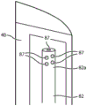
Fig. 4A-4C illustrate various arrangements of the snorkel system 80 that help ensure that the snorkel system 80 is properly positioned in the chamber 40 and that the chamber door 42 is not inadvertently inserted upside down causing misalignment or misalignment of the snorkel 82. As shown in fig. 4A, by providing a hard tip 83 at the top end 82a of the snorkel 82 having the correct dimensions relative to the size of the opening and chamber, this will help ensure that the opening tip of the snorkel is always at the top of the chamber and cannot be accidentally inserted incorrectly. The hard tip 83 must be of the correct size to keep it upright and not bend the vent tube 82 downward due to the weight of the hard tip, and the hard tip 83 is also large enough to remain on top of the chamber 40 and not be easily pulled out when the chamber door 42 is opened (e.g., for manual refilling). The combination of a suitably sized hard tip 83 and the curvature, orientation and rigidity of breather tube 82 helps to force the top end 82a of breather tube 82 to an upright position at the top of chamber 40. In another arrangement of the invention, as shown in fig. 4B, the size of chamber 40 is internally asymmetric such that a larger portion thereof is located above the open top to help ensure that breather tube 82 cannot be placed upside down in chamber 40 and that top end 82a of breather tube 82 will always be at the top of chamber 40. Additionally, in the arrangement shown in fig. 4C, the size of chamber 40 is internally asymmetric such that the larger portion thereof is near one side of the opening, so breather tube 82 will naturally be biased to fit on one side of chamber 40, further ensuring proper orientation.
Another option is an anti-kink feature of the present invention, as shown in fig. 5, which may be provided to prevent air vent tube 82 from bending and becoming blocked or kinked within chamber 40 and thereby impeding proper operation. By inserting internal spring 85 into the portion of breather tube 82 that should be located in the lower portion of the chamber, this will help maintain the proper curvature of that portion of breather tube 82 and prevent kinking of breather tube 82. The internal spring 85 also has the additional advantage of helping to maintain the vent tube in the proper position and orientation within the chamber 40.
Furthermore, a mechanism for ensuring that vent tube 82 and ports 44, 46, 144, 146 do not clog is desirable, particularly when fluids 112, such as mouthwash or antimicrobial liquids, which may have more mineral content, are used in the docking and charging station reservoir 110, as these fluids may dry and crystallize. It has been determined that by modifying the top end 82a of vent tube 82 (e.g., a top portion having a v-shaped cutting edge 86 as shown in fig. 6A) or inserting one or more holes 87 in top end 82a as shown in fig. 6B, the flow path of the liquid is disrupted, thereby preventing crystal formation or blockage of the liquid flow. This can help to ensure continued efficient operation of the mechanism of the present invention.
Another arrangement of the present invention is depicted in fig. 7, wherein vented membrane 90 is attached to top end 82a of vent tube 82. This will allow air present in chamber 40 to vent through breather tube 82 and through ports 46, 146, but will not allow any fluid to pass through membrane 90. Further, this arrangement may eliminate the need for a valve or safety device 57 on port 46 (although one valve or safety device 57 is shown in fig. 7) because there is no fluid passing through the port. This arrangement may also eliminate the need for additional spillover or shutdown safety mechanisms in the docking and charging station 100.
All definitions, as defined and used herein, should be understood to encompass dictionary definitions, definitions in documents incorporated by reference, and/or ordinary meanings of the defined terms.
The indefinite articles "a" and "an" as used in the specification and the claims herein should be understood as meaning "at least one" unless expressly stated to the contrary.
The term "and/or" as used herein in the specification and claims should be understood to mean "either or both" of the elements so combined, i.e., elements that are present in combination in some cases and elements that are present in isolation in other cases. Multiple elements listed with "and/or" should be understood in the same way, i.e., "one or more" of the elements so combined. In addition to the elements specifically identified by "and/or," other elements may optionally be present, whether related or unrelated to those elements specifically identified.
As used in the specification and claims herein, "or" should be understood to have the same meaning as "and/or" as defined above. For example, when items in a list are separated out, "or" and/or "should be understood as being inclusive, i.e., including at least one of a plurality of elements or a list of elements, but also including more than one, and optionally including additional unlisted items. Only words explicitly stated to the contrary, such as "only one of … …" or "only one of … …" or "consisting of … …" as used in the claims, are intended to include a plurality of elements or only one element of a list of elements. In general, the term "or" as used herein should be understood to mean exclusive (i.e., "one or the other, but not both") only when preceded by an exclusive term such as "either," one of … …, "" only one of … …, "or" explicitly only one of … ….
As used herein in the specification and in the claims, the term "at least one" with respect to one or more elements of a list should be understood to mean at least one element selected from any one or more of the elements of the list, but not necessarily including at least one of each element specifically listed in a list of elements, nor excluding any combination of elements in a list of elements. This definition also allows that elements may optionally be present other than the elements specifically identified within a list of elements to which the term "at least one" refers, whether related or unrelated to those elements specifically identified.
It will also be understood that, unless clearly indicated to the contrary, in any methods claimed herein that include more than one step or action, the order of the steps or actions of the method is not necessarily limited to the order in which the steps or actions of the method are described.
In the claims, as well as in the foregoing specification, all transitional words such as "comprise," include, "" carry, "" have, "" contain, "" involve, "" hold, "" consist of … … and the like are to be understood as open-ended, i.e., to mean including but not limited to. Only the transition words "consisting of … …" and "consisting essentially of … …" should be closed or semi-closed transition words, respectively.
Although a number of embodiments of the invention have been described and illustrated herein, those of ordinary skill in the art will readily envision a variety of other means and/or structures for performing the function and/or obtaining the results and/or one or more of the advantages described herein, and each of such variations and/or modifications is deemed to be within the scope of the embodiments of the invention described herein. More generally, those of ordinary skill in the art will readily recognize that all parameters, dimensions, materials, and configurations described herein are exemplary and that the actual parameters, dimensions, materials, and/or configurations will depend upon the specific application or applications for which the teachings of the present invention is/are used. Those skilled in the art will recognize, or be able to ascertain using no more than routine experimentation, many equivalents to the specific embodiments of the invention described herein. It is, therefore, to be understood that the foregoing embodiments are presented by way of example only and that, within the scope of the appended claims and equivalents thereto, other inventive embodiments may be realized that are not specifically described and claimed. The inventive embodiments of the present disclosure are directed to each individual feature, system, article, material, kit, and/or method described herein. In addition, any combination of two or more such features, systems, articles, materials, kits, and/or methods, if such features, systems, articles, materials, kits, and/or methods are not mutually inconsistent, is included within the scope of the present disclosure.
Claims (13)
1. An automatic filling mechanism for a hand-held fluid droplet appliance (10) for oral cleaning, the appliance (10) designed to be coupled to a docking and charging station (100) having a fluid reservoir (110), the automatic filling mechanism comprising:
a chamber (40) for holding a fluid, the chamber having an openable door (42) into the chamber;
the door having an O-ring (48) around its periphery and first and second female ports (44, 46) disposed through the door,
wherein the first female port (44) is an inlet that receives a fluid (112); and is
Wherein the second female port (46) is a liquid and air outlet interface with an attached vent tube system (80) comprising a vent tube (82) attached at a first end thereof to the second female port, a second end (82a) of the vent tube being open and located at the top of the chamber, the second female port and vent tube system for venting air and excess fluid from the chamber when fluid (112) enters the chamber from the fluid reservoir (110) through the first female port.
2. The automatic filling mechanism of claim 1 comprising flexible sealing portions (54, 56) surrounding the first female port (44) and the second female port (46), respectively.
3. The automatic filling mechanism of claim 1, comprising at least one check valve (55, 57) coupled to the first female port (44) or the second female port (46), respectively.
4. The automatic filling mechanism of claim 3 comprising a safety mechanism connected to the second female port (46).
5. The automatic filling mechanism of claim 1 further comprising a hard tip (83) at the second end (82a) of the vent tube (82) to help ensure proper positioning of the vent tube system (80) within the chamber (40).
6. The automatic filling mechanism of claim 1 wherein the chamber (40) is asymmetric.
7. The automatic filling mechanism of claim 1 further comprising an internal spring (85) in at least a portion of the vent tube (82).
8. The automatic filling mechanism of claim 5 wherein the hard tip (83) at the second end (82a) of the vent tube (82) has a v-shaped cutting edge (86).
9. The automatic filling mechanism of claim 5 wherein the hard tip (83) at the second end (82a) of the vent tube (82) has at least one hole (87) cut through the second end (82 a).
10. The automatic filling mechanism of claim 1 further comprising a gas permeable membrane (90) located at the second end (82a) of the vent tube (82).
11. A method of filling a handheld fluid droplet appliance (10) from a docking and charging station (100), the docking and charging station (100) having a pump (104), a fluid reservoir (110), a first male port (144) and a second male port (146), and a holder mechanism (160) for receiving the handheld fluid droplet appliance, the appliance for oral cleaning, the method comprising the steps of:
docking the handheld fluid droplet appliance (10) in the cradle mechanism (160) on the docking and charging station (100);
coupling first and second female ports (44, 46) on a door (42) of a chamber (40) of the handheld fluid droplet appliance (10) to the respective first and second male ports (144, 146) on the docking and charging station (100);
pumping fluid (112) from the reservoir (110) on the docking and charging station (100) through the joined first male port (144) and first female port (44) into the chamber (40) of the handheld fluid droplet appliance (10); and
expelling air and any excess fluid from the chamber (40) of the handheld fluid droplet device (10) through the joined second male port (146) and second female port (46);
wherein a vent tube (82) connected to the second female port (46) is inserted into the chamber (40) to ensure complete evacuation of air from the chamber (40) and to enable complete filling of the chamber (40) with liquid.
12. The method of claim 11, wherein a valve is provided that is configured to allow liquid to flow through the first male port (144) and the first female port (44) only when the valve is open.
13. The method of claim 11, wherein the bracket mechanism is configured to ensure that the first male port (144) and the second male port (146) of the docking and charging station (100) are properly aligned with the respective first female port (44) and the second female port (46) of the handheld fluid droplet appliance (10) prior to filling the handheld fluid droplet appliance.
Applications Claiming Priority (3)
| Application Number | Priority Date | Filing Date | Title |
|---|---|---|---|
| US201462097261P | 2014-12-29 | 2014-12-29 | |
| US62/097,261 | 2014-12-29 | ||
| PCT/IB2015/059756 WO2016108131A1 (en) | 2014-12-29 | 2015-12-18 | Automatic filling mechanism and method for a hand-held oral cleaning device |
Publications (2)
| Publication Number | Publication Date |
|---|---|
| CN107106274A CN107106274A (en) | 2017-08-29 |
| CN107106274B true CN107106274B (en) | 2021-03-26 |
Family
ID=55135463
Family Applications (1)
| Application Number | Title | Priority Date | Filing Date |
|---|---|---|---|
| CN201580071530.8A Active CN107106274B (en) | 2014-12-29 | 2015-12-18 | Automatic filling mechanism and method for hand-held oral cleaning device |
Country Status (6)
| Country | Link |
|---|---|
| US (1) | US10357345B2 (en) |
| EP (1) | EP3240498B1 (en) |
| JP (1) | JP6684811B2 (en) |
| CN (1) | CN107106274B (en) |
| RU (1) | RU2017126974A (en) |
| WO (1) | WO2016108131A1 (en) |
Families Citing this family (3)
| Publication number | Priority date | Publication date | Assignee | Title |
|---|---|---|---|---|
| WO2016124997A1 (en) * | 2015-02-05 | 2016-08-11 | Koninklijke Philips N.V. | Docking and charging station and filling operation for a hand-held oral cleaning device |
| KR102068548B1 (en) * | 2018-11-09 | 2020-01-22 | 주식회사 에이치앤케어 | Apparatus for cleaning oral |
| CN109381272A (en) * | 2018-12-05 | 2019-02-26 | 厦门洁博雅科技有限公司 | A kind of tooth washing device |
Citations (2)
| Publication number | Priority date | Publication date | Assignee | Title |
|---|---|---|---|---|
| JPH04306452A (en) * | 1991-04-03 | 1992-10-29 | Toto Ltd | Multipurose water delivery device |
| CN203061499U (en) * | 2013-01-28 | 2013-07-17 | 李增兴 | Ultrasonic spray washer |
Family Cites Families (15)
| Publication number | Priority date | Publication date | Assignee | Title |
|---|---|---|---|---|
| US5346324A (en) * | 1991-09-19 | 1994-09-13 | Youti Kuo | Dentifrice dispensing toothbrush with replaceable cartridge |
| US6402410B1 (en) * | 1999-01-13 | 2002-06-11 | Philips Oral Healthcare | Fluid-dispensing and refilling system for a power toothbrush |
| EP1379194B1 (en) * | 2001-02-12 | 2008-06-04 | Koninklijke Philips Electronics N.V. | Sonic power toothbrush with multiple containers |
| US6622333B1 (en) * | 2002-09-04 | 2003-09-23 | Rehco, Llc | Pneumatic-operated toothbrush |
| US7080980B2 (en) * | 2003-07-03 | 2006-07-25 | Michael Klupt | Dental hygiene device |
| US8317424B2 (en) * | 2004-06-03 | 2012-11-27 | The Gillette Company | Oral care device |
| US20050272001A1 (en) | 2004-06-03 | 2005-12-08 | Blain Christopher C | Oral care device |
| US20050271531A1 (en) * | 2004-06-03 | 2005-12-08 | Brown William R Jr | Oral care device |
| US20060078844A1 (en) * | 2004-10-07 | 2006-04-13 | Goldman Paul D | Oral care systems, oral care devices and methods of use |
| TW200934446A (en) * | 2007-10-22 | 2009-08-16 | Colgate Palmolive Co | Oral care implement with air flossing system |
| US9308064B2 (en) | 2010-07-26 | 2016-04-12 | Johnson & Johnson Consumer Inc. | Devices and methods for collecting and analyzing fluid samples from the oral cavity |
| KR101410048B1 (en) * | 2013-03-21 | 2014-06-20 | 안승희 | Oral cavity sterilization cleansing apparatus |
| US9980793B2 (en) * | 2013-11-27 | 2018-05-29 | Water Pik, Inc. | Oral hygiene system |
| WO2016108149A1 (en) * | 2014-12-29 | 2016-07-07 | Koninklijke Philips N.V. | Airfloss docking station charge detection |
| WO2016124997A1 (en) * | 2015-02-05 | 2016-08-11 | Koninklijke Philips N.V. | Docking and charging station and filling operation for a hand-held oral cleaning device |
-
2015
- 2015-12-18 EP EP15823795.8A patent/EP3240498B1/en active Active
- 2015-12-18 JP JP2017534698A patent/JP6684811B2/en active Active
- 2015-12-18 US US15/540,104 patent/US10357345B2/en active Active
- 2015-12-18 WO PCT/IB2015/059756 patent/WO2016108131A1/en active Application Filing
- 2015-12-18 CN CN201580071530.8A patent/CN107106274B/en active Active
- 2015-12-18 RU RU2017126974A patent/RU2017126974A/en unknown
Patent Citations (2)
| Publication number | Priority date | Publication date | Assignee | Title |
|---|---|---|---|---|
| JPH04306452A (en) * | 1991-04-03 | 1992-10-29 | Toto Ltd | Multipurose water delivery device |
| CN203061499U (en) * | 2013-01-28 | 2013-07-17 | 李增兴 | Ultrasonic spray washer |
Also Published As
| Publication number | Publication date |
|---|---|
| EP3240498A1 (en) | 2017-11-08 |
| US10357345B2 (en) | 2019-07-23 |
| JP2018500128A (en) | 2018-01-11 |
| CN107106274A (en) | 2017-08-29 |
| JP6684811B2 (en) | 2020-04-22 |
| EP3240498B1 (en) | 2019-10-23 |
| WO2016108131A1 (en) | 2016-07-07 |
| RU2017126974A (en) | 2019-01-31 |
| US20170367800A1 (en) | 2017-12-28 |
Similar Documents
| Publication | Publication Date | Title |
|---|---|---|
| US11826214B2 (en) | Oral irrigator | |
| CN113490469B (en) | Cartridge and base unit for use in an oral care implement | |
| US8801667B2 (en) | Pump for powered irrigator for sinus cavity rinse | |
| EP3253328B1 (en) | Docking and charging station and filling operation for a hand-held oral cleaning device | |
| CN107106274B (en) | Automatic filling mechanism and method for hand-held oral cleaning device | |
| JP5924415B2 (en) | Oral cleaning device | |
| JP2015535194A (en) | Undercounter installed foam dispenser system with permanent air compressor and refill unit | |
| US11779442B2 (en) | Teeth cleaning apparatus | |
| JP5307600B2 (en) | Liquid discharge container | |
| AU2013280697B2 (en) | Grit and foam dispenser | |
| CN106794057B (en) | Oral care device with pumpless fluid delivery system | |
| US20240115082A1 (en) | Dispensers having anti-leak air vents and bubble traps | |
| JP5538482B2 (en) | Water supply machine using a water bag filled with drinking water in a plastic film bag | |
| TW201433518A (en) | Off-axis inverted foam dispensers and refill units | |
| JP2012197113A (en) | Scalp-massaging device |
Legal Events
| Date | Code | Title | Description |
|---|---|---|---|
| PB01 | Publication | ||
| PB01 | Publication | ||
| SE01 | Entry into force of request for substantive examination | ||
| SE01 | Entry into force of request for substantive examination | ||
| GR01 | Patent grant | ||
| GR01 | Patent grant |