CN107087181B - Moving picture predictive decoding method - Google Patents
Moving picture predictive decoding method Download PDFInfo
- Publication number
- CN107087181B CN107087181B CN201710130238.XA CN201710130238A CN107087181B CN 107087181 B CN107087181 B CN 107087181B CN 201710130238 A CN201710130238 A CN 201710130238A CN 107087181 B CN107087181 B CN 107087181B
- Authority
- CN
- China
- Prior art keywords
- ref
- signal
- prediction
- reference samples
- block
- Prior art date
- Legal status (The legal status is an assumption and is not a legal conclusion. Google has not performed a legal analysis and makes no representation as to the accuracy of the status listed.)
- Active
Links
Images


Classifications
-
- H—ELECTRICITY
- H04—ELECTRIC COMMUNICATION TECHNIQUE
- H04N—PICTORIAL COMMUNICATION, e.g. TELEVISION
- H04N19/00—Methods or arrangements for coding, decoding, compressing or decompressing digital video signals
- H04N19/10—Methods or arrangements for coding, decoding, compressing or decompressing digital video signals using adaptive coding
- H04N19/102—Methods or arrangements for coding, decoding, compressing or decompressing digital video signals using adaptive coding characterised by the element, parameter or selection affected or controlled by the adaptive coding
- H04N19/117—Filters, e.g. for pre-processing or post-processing
-
- H—ELECTRICITY
- H04—ELECTRIC COMMUNICATION TECHNIQUE
- H04N—PICTORIAL COMMUNICATION, e.g. TELEVISION
- H04N19/00—Methods or arrangements for coding, decoding, compressing or decompressing digital video signals
- H04N19/50—Methods or arrangements for coding, decoding, compressing or decompressing digital video signals using predictive coding
- H04N19/503—Methods or arrangements for coding, decoding, compressing or decompressing digital video signals using predictive coding involving temporal prediction
- H04N19/51—Motion estimation or motion compensation
- H04N19/513—Processing of motion vectors
- H04N19/517—Processing of motion vectors by encoding
- H04N19/52—Processing of motion vectors by encoding by predictive encoding
-
- H—ELECTRICITY
- H04—ELECTRIC COMMUNICATION TECHNIQUE
- H04N—PICTORIAL COMMUNICATION, e.g. TELEVISION
- H04N19/00—Methods or arrangements for coding, decoding, compressing or decompressing digital video signals
- H04N19/50—Methods or arrangements for coding, decoding, compressing or decompressing digital video signals using predictive coding
- H04N19/59—Methods or arrangements for coding, decoding, compressing or decompressing digital video signals using predictive coding involving spatial sub-sampling or interpolation, e.g. alteration of picture size or resolution
-
- G—PHYSICS
- G06—COMPUTING; CALCULATING OR COUNTING
- G06T—IMAGE DATA PROCESSING OR GENERATION, IN GENERAL
- G06T9/00—Image coding
-
- H—ELECTRICITY
- H04—ELECTRIC COMMUNICATION TECHNIQUE
- H04N—PICTORIAL COMMUNICATION, e.g. TELEVISION
- H04N19/00—Methods or arrangements for coding, decoding, compressing or decompressing digital video signals
- H04N19/10—Methods or arrangements for coding, decoding, compressing or decompressing digital video signals using adaptive coding
- H04N19/102—Methods or arrangements for coding, decoding, compressing or decompressing digital video signals using adaptive coding characterised by the element, parameter or selection affected or controlled by the adaptive coding
- H04N19/103—Selection of coding mode or of prediction mode
- H04N19/105—Selection of the reference unit for prediction within a chosen coding or prediction mode, e.g. adaptive choice of position and number of pixels used for prediction
-
- H—ELECTRICITY
- H04—ELECTRIC COMMUNICATION TECHNIQUE
- H04N—PICTORIAL COMMUNICATION, e.g. TELEVISION
- H04N19/00—Methods or arrangements for coding, decoding, compressing or decompressing digital video signals
- H04N19/10—Methods or arrangements for coding, decoding, compressing or decompressing digital video signals using adaptive coding
- H04N19/134—Methods or arrangements for coding, decoding, compressing or decompressing digital video signals using adaptive coding characterised by the element, parameter or criterion affecting or controlling the adaptive coding
- H04N19/136—Incoming video signal characteristics or properties
-
- H—ELECTRICITY
- H04—ELECTRIC COMMUNICATION TECHNIQUE
- H04N—PICTORIAL COMMUNICATION, e.g. TELEVISION
- H04N19/00—Methods or arrangements for coding, decoding, compressing or decompressing digital video signals
- H04N19/10—Methods or arrangements for coding, decoding, compressing or decompressing digital video signals using adaptive coding
- H04N19/134—Methods or arrangements for coding, decoding, compressing or decompressing digital video signals using adaptive coding characterised by the element, parameter or criterion affecting or controlling the adaptive coding
- H04N19/157—Assigned coding mode, i.e. the coding mode being predefined or preselected to be further used for selection of another element or parameter
- H04N19/159—Prediction type, e.g. intra-frame, inter-frame or bidirectional frame prediction
-
- H—ELECTRICITY
- H04—ELECTRIC COMMUNICATION TECHNIQUE
- H04N—PICTORIAL COMMUNICATION, e.g. TELEVISION
- H04N19/00—Methods or arrangements for coding, decoding, compressing or decompressing digital video signals
- H04N19/10—Methods or arrangements for coding, decoding, compressing or decompressing digital video signals using adaptive coding
- H04N19/169—Methods or arrangements for coding, decoding, compressing or decompressing digital video signals using adaptive coding characterised by the coding unit, i.e. the structural portion or semantic portion of the video signal being the object or the subject of the adaptive coding
- H04N19/17—Methods or arrangements for coding, decoding, compressing or decompressing digital video signals using adaptive coding characterised by the coding unit, i.e. the structural portion or semantic portion of the video signal being the object or the subject of the adaptive coding the unit being an image region, e.g. an object
- H04N19/176—Methods or arrangements for coding, decoding, compressing or decompressing digital video signals using adaptive coding characterised by the coding unit, i.e. the structural portion or semantic portion of the video signal being the object or the subject of the adaptive coding the unit being an image region, e.g. an object the region being a block, e.g. a macroblock
-
- H—ELECTRICITY
- H04—ELECTRIC COMMUNICATION TECHNIQUE
- H04N—PICTORIAL COMMUNICATION, e.g. TELEVISION
- H04N19/00—Methods or arrangements for coding, decoding, compressing or decompressing digital video signals
- H04N19/50—Methods or arrangements for coding, decoding, compressing or decompressing digital video signals using predictive coding
- H04N19/503—Methods or arrangements for coding, decoding, compressing or decompressing digital video signals using predictive coding involving temporal prediction
- H04N19/51—Motion estimation or motion compensation
- H04N19/513—Processing of motion vectors
- H04N19/521—Processing of motion vectors for estimating the reliability of the determined motion vectors or motion vector field, e.g. for smoothing the motion vector field or for correcting motion vectors
-
- H—ELECTRICITY
- H04—ELECTRIC COMMUNICATION TECHNIQUE
- H04N—PICTORIAL COMMUNICATION, e.g. TELEVISION
- H04N19/00—Methods or arrangements for coding, decoding, compressing or decompressing digital video signals
- H04N19/50—Methods or arrangements for coding, decoding, compressing or decompressing digital video signals using predictive coding
- H04N19/503—Methods or arrangements for coding, decoding, compressing or decompressing digital video signals using predictive coding involving temporal prediction
- H04N19/51—Motion estimation or motion compensation
- H04N19/573—Motion compensation with multiple frame prediction using two or more reference frames in a given prediction direction
-
- H—ELECTRICITY
- H04—ELECTRIC COMMUNICATION TECHNIQUE
- H04N—PICTORIAL COMMUNICATION, e.g. TELEVISION
- H04N19/00—Methods or arrangements for coding, decoding, compressing or decompressing digital video signals
- H04N19/50—Methods or arrangements for coding, decoding, compressing or decompressing digital video signals using predictive coding
- H04N19/587—Methods or arrangements for coding, decoding, compressing or decompressing digital video signals using predictive coding involving temporal sub-sampling or interpolation, e.g. decimation or subsequent interpolation of pictures in a video sequence
-
- H—ELECTRICITY
- H04—ELECTRIC COMMUNICATION TECHNIQUE
- H04N—PICTORIAL COMMUNICATION, e.g. TELEVISION
- H04N19/00—Methods or arrangements for coding, decoding, compressing or decompressing digital video signals
- H04N19/50—Methods or arrangements for coding, decoding, compressing or decompressing digital video signals using predictive coding
- H04N19/593—Methods or arrangements for coding, decoding, compressing or decompressing digital video signals using predictive coding involving spatial prediction techniques
-
- H—ELECTRICITY
- H04—ELECTRIC COMMUNICATION TECHNIQUE
- H04N—PICTORIAL COMMUNICATION, e.g. TELEVISION
- H04N19/00—Methods or arrangements for coding, decoding, compressing or decompressing digital video signals
- H04N19/60—Methods or arrangements for coding, decoding, compressing or decompressing digital video signals using transform coding
- H04N19/625—Methods or arrangements for coding, decoding, compressing or decompressing digital video signals using transform coding using discrete cosine transform [DCT]
-
- H—ELECTRICITY
- H04—ELECTRIC COMMUNICATION TECHNIQUE
- H04N—PICTORIAL COMMUNICATION, e.g. TELEVISION
- H04N19/00—Methods or arrangements for coding, decoding, compressing or decompressing digital video signals
- H04N19/80—Details of filtering operations specially adapted for video compression, e.g. for pixel interpolation
- H04N19/82—Details of filtering operations specially adapted for video compression, e.g. for pixel interpolation involving filtering within a prediction loop
-
- H—ELECTRICITY
- H04—ELECTRIC COMMUNICATION TECHNIQUE
- H04N—PICTORIAL COMMUNICATION, e.g. TELEVISION
- H04N19/00—Methods or arrangements for coding, decoding, compressing or decompressing digital video signals
- H04N19/85—Methods or arrangements for coding, decoding, compressing or decompressing digital video signals using pre-processing or post-processing specially adapted for video compression
- H04N19/86—Methods or arrangements for coding, decoding, compressing or decompressing digital video signals using pre-processing or post-processing specially adapted for video compression involving reduction of coding artifacts, e.g. of blockiness
-
- H—ELECTRICITY
- H04—ELECTRIC COMMUNICATION TECHNIQUE
- H04N—PICTORIAL COMMUNICATION, e.g. TELEVISION
- H04N19/00—Methods or arrangements for coding, decoding, compressing or decompressing digital video signals
- H04N19/46—Embedding additional information in the video signal during the compression process
-
- H—ELECTRICITY
- H04—ELECTRIC COMMUNICATION TECHNIQUE
- H04N—PICTORIAL COMMUNICATION, e.g. TELEVISION
- H04N19/00—Methods or arrangements for coding, decoding, compressing or decompressing digital video signals
- H04N19/60—Methods or arrangements for coding, decoding, compressing or decompressing digital video signals using transform coding
- H04N19/61—Methods or arrangements for coding, decoding, compressing or decompressing digital video signals using transform coding in combination with predictive coding
Abstract
Provided is a moving picture predictive decoding method. In the prediction signal generation step, a series of adjacent reference samples are obtained from reproduced blocks around a stored target block, an interpolation process is performed between 2 or more key reference samples at predetermined positions in the reference samples to generate interpolated reference samples, the interpolated reference samples are extrapolated according to an intra prediction mode to generate an intra prediction signal, and the interpolation process of the reference samples ref [ i ] is based on the expression ((64-i) × BL + i × AL +32)/64 in the case where the series of adjacent reference samples are represented by an array ref [ x ], ref [0] is assumed to be the key reference sample BL, and ref [64] is assumed to be the key reference sample AL, where x is an integer of 0 to 128, and i is an integer of 1 to 63.
Description
The patent application of the present invention is a divisional application of an invention patent application named "moving picture predictive encoding device, moving picture predictive encoding method, moving picture predictive decoding device, and moving picture predictive decoding method", having an application date of 2013, 6 and 17 months, an international application number of "PCT/JP 2013/066616", and a national application number of "201380041882. X".
Technical Field
The present invention relates to a moving picture prediction encoding device and method, and a moving picture prediction decoding device and method, and more particularly to filtering processing for reference samples used for intra-picture prediction encoding.
Background
Compression encoding technology is used to efficiently transmit and store moving image data. In the case of moving pictures, MPEG 1-4 or H.261-H.264 systems are widely used.
In these encoding methods, an image to be encoded is divided into a plurality of blocks, and then encoding/decoding processing is performed. In intra-screen predictive coding, a prediction signal is generated using an adjacent reproduced image signal (an image signal obtained by restoring compressed image data) located within the same screen as a target block, and then a difference signal obtained by subtracting the prediction signal from the signal of the target block is coded. In the inter-picture prediction encoding, motion correction is performed with reference to an adjacent reproduced image signal located in a different picture from a target block, a prediction signal is generated, and a difference signal obtained by subtracting the prediction signal from a signal of the target block is encoded.
In normal inter-picture prediction (inter-frame prediction) encoding, a prediction signal is generated by searching for a signal similar to the pixel signal from a picture that has been reproduced, for a block to be encoded. Then, a motion vector, which is a spatial displacement amount between the target block and the region constituted by the searched signal, and a residual signal between the pixel signal of the target block and the prediction signal are encoded. The technique of searching for a motion vector for each block is called block matching.
Fig. 10 is a schematic diagram for explaining the block matching process. Here, the order of generating the prediction signal will be described by taking the target block 702 on the picture 701 to be encoded as an example. The reference picture 703 is reproduced, and the region 704 is spatially the same region as the object block 702. In block matching, a search range 705 surrounding the area 704 is set, and an area 706 having the smallest sum of absolute differences with the pixel signals of the target block 702 is detected from the pixel signals in the search range. The signal of the region 706 becomes a prediction signal, and the amount of displacement from the region 704 to the region 706 is detected as a motion vector 707. Also, the following methods are often used: a plurality of reference pictures 703 are prepared, and a reference picture to be subjected to block matching is selected for each target block, and reference picture selection information is detected. In h.264, a plurality of prediction types having different block sizes for encoding a motion vector are prepared in order to cope with a change in local characteristics of an image. The prediction type of h.264 is described in patent document 2, for example.
In the intra prediction (intra prediction) encoding of h.264, a method of extrapolating reproduced pixel values adjacent to a block to be encoded in a predetermined direction to generate a prediction signal is employed. Fig. 11 is a schematic diagram for explaining an intra-picture prediction method used in itu h.264. In fig. 11 a, a target block 802 is a block to be encoded, and a pixel group (reference sample group) 801 including pixels a to M adjacent to the boundary of the target block 802 is an adjacent area and is an image signal that has been reproduced in the past processing.
In this case, a pixel group (reference sample group) 801, which is an adjacent pixel located immediately above the target block 802, is stretched downward to generate a prediction signal. In fig. 11B, the reproduced pixels (I to L) on the left side of the target block 804 are stretched to the right side to generate prediction signals. A specific method of generating a prediction signal is described in patent document 1, for example. Differences between the 9 prediction signals generated by the methods shown in fig. 11(a) to (I) and the pixel signals of the target block are obtained, and the prediction signal having the smallest difference value is set as the optimum prediction signal. As described above, by extrapolating the pixels, a prediction signal (intra prediction sample) can be generated. The above is described in the following patent document 1.
In addition, in the intra-screen prediction disclosed in non-patent document 1, 25 (34 in total) prediction signal generation methods different in the stretching direction of the reference sample are prepared in addition to the above-described 9 types.
In non-patent document 1, low-pass filtering is performed on the reference sample before generating the prediction signal in order to suppress distortion occurring in the reference sample. Specifically, a weight coefficient of 1 is applied to the reference sample: 2: the extrapolation prediction is performed after the 121 filter of 1. This process is called intra smoothing.
The intra prediction of non-patent document 1 will be described with reference to fig. 7 and 8. Fig. 7 shows an example of block division. The 5 blocks 220, 230, 240, 250, 260 adjacent to the object block 210 having the block size of N × N samples have been reproduced. For intra prediction of the target block 210, reference samples denoted by ref [ x ] (x is 0 to 4N) are used. Fig. 8 shows a process flow of intra prediction. First, in step 310, the prediction signal generator that performs the intra-picture prediction process acquires a reference sample ref [ x ] (x is 0 to 4N) from a memory that stores the reproduced pixels. In this case, the neighboring blocks are not reproduced due to the coding order or the like, and all of the 4N +1 reference samples ref [ x ] may not be obtained. At this time, 4N +1 reference samples are prepared by replacing a sample that does not exist in the padding (padding) process (copying of sample values existing in the vicinity). The filling process is described in detail in non-patent document 1. Next, in step 320, the prediction signal generator performs smoothing processing on the reference sample using the 121 filter. Finally, in step 330, the prediction signal generator estimates a signal in the target block by extrapolation (direction of intra-picture prediction) to generate a prediction signal (intra-prediction sample).
Documents of the prior art
Patent document
Patent document 1: U.S. patent publication No. 6765964
Patent document 2: U.S. patent publication No. 7003035
Non-patent document
Non-patent document 1: B.Bross et al, "High Efficiency Video Coding (HEVC) texture draft 8", Joint collagen Team on Video Coding (JCT-VC) of ITU-T SG16 WP3 and ISO/IEC JTC1/SC29/WG11, JCTVC-J1003,10th Meeting: stockholm, Sweden,11-20July,2012.
Disclosure of Invention
Problems to be solved by the invention
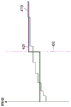
Although fig. 9 shows an example of a signal of a similar flat region of pixel values, when the original pixel values (original sample values) 410 are encoded by coarse quantization, the reproduction values (reproduction sample values) 420 within a block become fixed values, and a step-like distortion occurs at a block boundary 430. This distortion is considered to be block noise, and is usually removed by applying filtering for removing block noise to the reproduced image. However, since the reference sample used for the intra prediction is a signal before the filtering process for removing the block noise, the block noise remaining in the reference sample at the block boundary propagates to the prediction signal (intra prediction sample) of the target block by the intra prediction. The block noise propagated to the prediction signal cannot be removed by the block noise removal processing for the reproduced signal, and therefore, is directly propagated to the reference sample group of the next target block.
In non-patent document 1, 34 different extrapolation directions are prepared in the extrapolation method for intra-picture prediction (directions of intra-picture prediction), and therefore, block noise changes directions and propagates. As a result, a plurality of false contours are generated in the reproduced signal of the flat area in the image. In particular, when noise propagates to a large-sized block, a pseudo contour crosses the large block, and the visual effect is large.
The 121 filter described in the background art has an effect of removing noise in the reference sample, but since the number of taps is short, the noise in a staircase shape shown in fig. 9 is removed by the extraction method.
Therefore, an object of the present invention is to suppress artifacts such as the above-described false contour.
Means for solving the problems
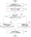
A moving picture predictive decoding method according to one aspect of the present invention is a moving picture predictive decoding method executed by a moving picture predictive decoding apparatus, the moving picture predictive decoding method including the steps of: a decoding step of decoding, from compressed data that has been divided into a plurality of blocks and encoded, compressed data that indicates an intra prediction mode of an intra prediction method and a residual signal of a target block to be decoded; a prediction signal generation step of generating an intra prediction signal using the intra prediction mode and reproduced reference samples adjacent to the target block; a residual signal restoration step of restoring a reproduced residual signal of the target block from compressed data of the residual signal; and a block storage step of restoring a pixel signal of the target block by adding the prediction signal and the reproduction residual signal, and storing the pixel signal of the restored target block as the reference sample, wherein in the prediction signal generation step, a series of adjacent reference samples are obtained from a reproduced block around the stored target block, interpolation processing is performed between 2 or more key reference samples at predetermined positions in the reference samples to generate interpolated reference samples, the interpolated reference samples are extrapolated in accordance with the intra prediction mode to generate the intra prediction signal, and in the prediction signal generation step, when the series of adjacent reference samples are represented by an array ref [ x ], ref [0] is set as a key reference sample BL, and [64] is set as a key reference sample AL, the interpolation process of the reference sample ref [ i ] is based on the formula ((64-i) × BL + i × AL +32)/64, where x is an integer of 0 to 128 and i is an integer of 1 to 63.
A moving picture predictive decoding method according to one aspect of the present invention is a moving picture predictive decoding method executed by a moving picture predictive decoding apparatus, the moving picture predictive decoding method including the steps of: a decoding step of decoding, from compressed data that has been divided into a plurality of blocks and encoded, compressed data that indicates an intra prediction mode of an intra prediction method and a residual signal of a target block to be decoded; a prediction signal generation step of generating an intra prediction signal using the intra prediction mode and reproduced reference samples adjacent to the target block; a residual signal restoration step of restoring a reproduced residual signal of the target block from compressed data of the residual signal; and a block storage step of restoring a pixel signal of the target block by adding the prediction signal and the reproduction residual signal, and storing the pixel signal of the restored target block as the reference sample, wherein in the prediction signal generation step, a series of adjacent reference samples are obtained from a reproduced block around the stored target block, interpolation processing is performed between 2 or more key reference samples at predetermined positions in the reference samples to generate interpolated reference samples, the interpolated reference samples are extrapolated in accordance with the intra prediction mode to generate the intra prediction signal, and in the prediction signal generation step, when the series of adjacent reference samples are represented by an array ref [ x ], ref [64] is set as a key reference sample AL, and [128] is set as a key reference sample AR, the interpolation process of the reference sample ref [64+ i ] is based on the formula ((64-i) × AL + i × AR +32)/64, where x is an integer of 0 to 128 and i is an integer of 1 to 63.
Effects of the invention
According to the filter processing for the reference sample by the biquadratic interpolation of the present invention, the signal in the reference sample is gently changed using the samples at both ends of the reference sample, and therefore, artificial noise such as a false contour can be suppressed.
Drawings
Fig. 1 is a block diagram showing a moving picture prediction encoding device according to an embodiment of the present invention.
Fig. 2 is a block diagram showing a moving picture prediction decoding apparatus according to an embodiment of the present invention.
Fig. 3 is a flowchart illustrating an intra-picture prediction method according to an embodiment of the present invention.
Fig. 4 is a flowchart showing a different example of the intra prediction method according to the embodiment of the present invention.
Fig. 5 is a diagram showing a hardware configuration of a computer for executing a program recorded in a recording medium.
Fig. 6 is an overview of a computer for executing a program recorded in a recording medium.
Fig. 7 is a diagram illustrating an example of a reference sample used for intra prediction.
Fig. 8 is a flowchart illustrating an intra prediction method in the related art.
Fig. 9 is a diagram illustrating a relationship between an original signal and a reproduced signal in a flat area.
Fig. 10 is a schematic diagram for explaining a motion estimation process in inter-picture prediction.
Fig. 11 is a schematic diagram for explaining intra-picture prediction based on extrapolation of a reference sample.
Fig. 12 is a diagram illustrating a different example of a reference sample used for intra prediction.
Fig. 13 is a flowchart illustrating a process of the prediction signal generator 103 of fig. 1.
Fig. 14 is a flowchart illustrating a process of the prediction signal generator 208 of fig. 2.
Fig. 15 is a flowchart showing a 2 nd different example of the intra prediction method according to the embodiment of the present invention.
Fig. 16 is a block diagram showing the configuration of a moving image predictive encoding program.
Fig. 17 is a block diagram showing the configuration of a moving picture prediction decoding program.
Detailed Description
Next, an embodiment of the present invention will be described with reference to fig. 1 to 7 and 13 to 17.
Fig. 1 is a block diagram showing a moving picture prediction encoding device 100 according to an embodiment of the present invention. As shown in fig. 1, the moving picture predictive encoding apparatus 100 has an input terminal 101, a block divider 102, a prediction signal generator 103, a frame memory 104, a subtractor 105, a converter 106, a quantizer 107, an inverse quantizer 108, an inverse converter 109, an adder 110, an entropy encoder 111, an output terminal 112, a block memory 113, and a loop filter 114. The subtractor 105, the converter 106, and the quantizer 107 correspond to "an encoding unit" recited in the scope of claims. The inverse quantizer 108, the inverse transformer 109, and the adder 110 correspond to "decoding means" described in the scope of claims. The frame memory 104 corresponds to an "image storage unit", and the block memory 113 corresponds to a "block storage unit".
Next, the operation of the moving picture prediction encoding apparatus 100 configured as described above will be described. A moving image signal composed of a plurality of images is input to the input terminal 101. An image to be encoded is divided into a plurality of regions by a block divider 102. In the embodiment of the present invention, as illustrated in fig. 7, the block size is not limited. A plurality of block sizes and shapes may mixedly exist in 1 picture. The coding order of blocks is described in, for example, non-patent document 1. Next, a prediction signal is generated for a region to be encoded (hereinafter, referred to as a target block). In the embodiment of the present invention, 2 prediction methods of inter-picture prediction and intra-picture prediction are used. The prediction signal generation process in the prediction signal generator 103 will be described later using fig. 13.
The predicted signal (via line L103) is subtracted from the signal of the target block (via line L102) by a subtractor 105, and a residual signal is generated. The residual signal is subjected to discrete cosine transform by a transformer 106, and each transform coefficient is quantized by a quantizer 107. The entropy encoder 111 encodes the quantized transform coefficient and transmits the encoded transform coefficient together with prediction information necessary for generating a prediction signal from an output terminal 112.
In order to perform intra-picture prediction or inter-picture prediction on a subsequent target block, the signal of the compressed target block is subjected to inverse processing and restored. That is, the quantized transform coefficient is inversely quantized by the inverse quantizer 108, and then inverse discrete cosine transformed by the inverse transformer 109, thereby restoring the residual signal. The adder 110 adds the restored residual signal and the prediction signal supplied from the line L103, and reproduces the signal of the target block. The reproduced block signal is stored in the block memory 113 for intra-picture prediction. A reproduced image composed of the reproduced signal is stored in the frame memory 104 after block noise generated in the reproduced image is removed by the loop filter 114.
The predicted signal processing flow in the predicted signal generator 103 will be described with reference to fig. 13. First, in step S302, prediction information necessary for inter-picture prediction is generated. Specifically, a reproduced image restored after past encoding is used as a reference image, and a motion vector and a reference picture that give a prediction signal having the smallest error with respect to a target block are searched for from the reference image. At this time, the target block is input via line L102, and the reference image is input via line L104. As the reference image, a plurality of images encoded and restored in the past are used as the reference image. Details are the same as those of h.264 or non-patent document 1 which is a conventional technique.
In step S303, prediction information necessary for intra prediction is generated. As shown in fig. 7, prediction signals are generated for a plurality of directions of intra-picture prediction using already reproduced pixel values spatially adjacent to the target block. Then, a prediction direction (intra prediction mode) for providing a prediction signal having the smallest error with respect to the target block is determined. At this time, the prediction signal generator 103 acquires the reproduced pixel signals located in the same picture from the block memory 113 via the line L113 as reference samples, and extrapolates these signals to generate an intra-picture prediction signal.
Next, in step S304, a prediction method to be applied to the target block is selected from inter-picture prediction and intra-picture prediction. For example, a prediction method that gives a prediction value with a small error with respect to the target block is selected. Alternatively, the up-to-encoding process may be actually performed for 2 prediction methods, and the smaller evaluation value may be selected based on the relationship between the generated code amount and the sum of absolute values of the encoding error images. The selection information of the selected prediction method is sent to the entropy encoder 111 via the line L112 as information necessary for generating a prediction signal, is encoded, and is then sent from the output terminal 112 (step S305).
If the prediction method selected in step S306 is inter-picture prediction, a prediction signal is generated in step S307 based on the motion information (motion vector and reference picture information), and the generated inter-picture prediction signal is output to the subtractor 105 via the line L103. In step S308, the motion information is sent to the entropy encoder 111 via the line L112 as information necessary for generating the prediction signal, is encoded, and is then sent from the output terminal 112.
If the prediction method selected in step S306 is intra prediction, a prediction signal is generated in step S309 in accordance with the intra prediction mode, and the generated intra prediction signal is output to the subtractor 105 via the line L103. In step S310, the intra prediction mode is sent to the entropy encoder 111 via the line L112 as information necessary for generating a prediction signal, is encoded, and is then sent from the output terminal 112.
The encoding method used in the entropy encoder 111 may be arithmetic encoding or variable length encoding.
Fig. 2 is a block diagram of a moving picture prediction decoding apparatus 200 according to an embodiment of the present invention. As shown in fig. 2, the moving picture prediction decoding apparatus 200 has an input terminal 201, a data parser 202, an inverse quantizer 203, an inverse converter 204, an adder 205, a prediction signal generator 208, a frame memory 207, an output terminal 206, a loop filter 209, and a block memory 215. The inverse quantizer 203 and the inverse transformer 204 correspond to a "decoding unit" recited in the scope of claims. As the decoding means, means other than the above may be used. The inverse converter 204 may not be provided. The frame memory 207 corresponds to an "image storage unit", and the block memory 215 corresponds to a "block storage unit".
Next, the operation of the moving picture prediction decoding apparatus 200 configured as described above will be described. The compressed data compressed and encoded by the above method is input from the input terminal 201. The compressed data includes a residual signal obtained by predictive coding a target block obtained by dividing an image into a plurality of blocks, and information necessary for generating a prediction signal. As illustrated in fig. 7, the block size is not limited. A plurality of block sizes and shapes may mixedly exist in 1 picture. The decoding order of blocks is described in, for example, non-patent document 1. The information required for generating the prediction signal includes prediction method selection information and motion information (in the case of inter-picture prediction) or an intra prediction mode (in the case of intra-picture prediction).
The data parser 202 decodes a residual signal of a target block, information required to generate a prediction signal, and a quantization parameter from compressed data. The residual signal of the decoded target block is inversely quantized by the inverse quantizer 203 in accordance with the quantization parameter (via the line L202). Further, the inversely quantized residual signal is subjected to inverse discrete cosine transform by the inverse transformer 204, and as a result, the residual signal is restored. Then, information necessary for generating the prediction signal is sent to the prediction signal generator 208 via the line L206. The prediction signal generator 208 generates a prediction signal of the target block based on information required to generate the prediction signal. The process of generating the prediction signal in the prediction signal generator 208 will be described later with reference to fig. 14. The generated prediction signal is sent to the adder 205 via the line L208, added to the restored residual signal, reproduced from the target block signal, and output to the loop filter 209 via the line L205, while being stored in the block memory 215 for use in the intra-picture prediction of the subsequent block. The loop filter 209 removes block noise from the reproduction signal input via the line L205, and the reproduction image from which the block noise is removed is stored in the frame memory 207 as a reproduction image used in decoding/reproduction of a subsequent image.
The predicted signal processing flow in the predicted signal generator 208 will be described with reference to fig. 14. First, in step S402, the data analyzer 202 acquires a prediction method after decoding.
When the prediction method after decoding is inter-picture prediction (step S403), the data analyzer 202 acquires the decoded motion information (motion vector and reference picture information) (step S404), accesses the frame memory 207 based on the motion information, acquires reference signals from a plurality of reference images, and generates prediction signals (step S405).
When the decoded prediction method is intra-picture prediction (step S403), the decoded intra-prediction mode is acquired by the data analyzer 202 (step S406), the block memory 215 is accessed, the reproduced pixel signal adjacent to the target block is acquired as a reference sample, and a prediction signal is generated from the intra-prediction mode (step S407). The generated prediction signal is output to the adder 205 via the L208.
The decoding method used in the data parser 202 may be arithmetic decoding or variable length decoding.
Next, an intra-picture prediction method according to an embodiment of the present invention will be described with reference to fig. 3 and 7. That is, the details of step S309 in fig. 13 and step S407 in fig. 14, that is, the method of estimating the intra prediction sample of the target block by the extrapolation method based on the intra prediction mode using the reference sample acquired from the block memory 113 in fig. 1 or the block memory 215 in fig. 2 will be described.
In the present invention, in order to suppress the generation of noise such as a false contour, which is a problem to be solved by the present invention, a biquadratic interpolation process is applied to a reference sample group used for intra-picture prediction with respect to a block that is a cause of the false contour. By smoothing the change in the signal of the reference sample group, the occurrence of step-like noise generated at the block boundary of the reference sample group is suppressed.
The biquad interpolation process applied to the reference sample group will be described with reference to fig. 7. When the block size of the target block 210 is N × N samples, 4N +1 reference sample groups 270(ref [ x ] (x is 0 to 4N)) are formed by using reproduced signals belonging to 5 reproduced blocks 220, 230, 240, 250, and 260 around the target block. In the present embodiment, 3 reference samples, i.e., the reference sample BL on the lower left side and the reference sample AR on the upper right side of the end of the reference sample group 270 are ref [0], ref [4N ], and the reference sample AL on the upper left side of the target block at the center of the reference sample group 270 are defined as the key reference samples for the double interpolation. At this time, interpolation processing is performed on 4N +1 reference samples as described below.
ref’[0]=ref[0](1)
ref’[i]=BL+(i*(AL-BL)+N)/2N (i=1~2N-1) (2)
ref’[2N]=ref[2N](3)
ref’[2N+i]=AL+(i*(AR-AL)+N)/2N (i=1~2N-1) (4)
ref’[4N]=ref[4N](5)
Here, ref' [ x ] (x is 0 to 4N) represents a value of the interpolated reference sample (interpolated reference samples). In addition, the formulas (2) and (4) may be modified as in the formulas (2) 'and (4)' respectively.
ref’[i]=((2N-i)*BL+i*AL+N)/2N (i=1~2N-1) (2)’
ref’[2N+i]=((2N-i)*AL+i*AR+N)/2N (i=1~2N-1) (4)’
In this way, the levels of the reference sample values after the interpolation process adjacent to the target block are gently changed by generating the reference samples between BL to AL by the double-interpolation using the key reference samples BL and AL and generating the reference samples between AL to AR by the double-interpolation using the key reference samples AL and AR. As a result, propagation of block noise to the prediction signal can be suppressed.
Next, the criterion for determining a reference sample to which the double-primary interpolation is applied will be described with reference to fig. 7. In the present embodiment, the determination is performed using 3 key reference samples, 2 reference samples of the block boundary, and 2 thresholds. Here, THRESHOLD _ ABOVE and THRESHOLD _ LEFT are used to determine whether or not to apply double interpolation to the reference sample ref [ x ] (x is 2N +1 to 4N-1) at the upper end and the reference sample ref [ x ] (x is 1 to 2N-1) at the LEFT end of the target block, respectively. A bi-linear interpolation is applied to the reference samples that satisfy the criterion.
In the present embodiment, the following criteria are used. In the following 2 expressions, interleave _ Above and interleave _ Left are logical values, and are called "tube (1)" when the right expression is satisfied, and are called "false (0)" when the right expression is not satisfied, and the conventional intrasmoothing by a 121 filter is applied.
Interpolate_Left=abs(BL+AL-2*ref[N])<THRESHOLD_LEFT (6)
Interpolate_Above=abs(AL+AR-2*ref[3N])<THRESHOLD_ABOVE (7)
When the values of BL, AL, and ref [3N ] are arranged on a straight line, the value of BL + AL-2 × ref [ N ] becomes 0. Similarly, when the values of AL, AR, and ref [3N ] are arranged on a straight line, the value of AL + AR-2 × ref [3N ] is also 0. That is, the 2 equation pairs described above compare the magnitude of the deviation (deviation) of ref [ N ] from the straight line connecting AL from BL and the magnitude of the deviation (deviation) of ref [3N ] from the straight line connecting AL and AR with respective thresholds. If the calculated 2 deviations are less than the corresponding THRESHOLD value THRESHOLD _ ABOVE or THRESHOLD _ LEFT, the logic value (interplate _ ABOVE or interplate _ LEFT) becomes true and a two-fold interpolation is applied to the reference sample. In equations (6) and (7), abs (x) is the absolute value of x calculated.
In this case, the values of the 2 THRESHOLDs (THRESHOLD _ ABOVE and THRESHOLD _ LEFT) may be fixed values set in advance, or may be encoded in units of frames or in units of slices (slices) in which a plurality of blocks are collected and restored by a decoder. Further, the encoding may be performed in units of blocks and the decoding may be performed by a decoder. In fig. 2, the 2 thresholds are decoded by the data parser 202 and output to the prediction signal generator 208 for use in the generation of an intra-picture prediction signal as described in detail below with respect to fig. 3 and 4.
Fig. 3 shows a flowchart of a process of estimating intra-prediction samples by extrapolation (direction of intra-picture prediction). First, in step 510, the prediction signal generator (103 or 208, hereinafter, abbreviated) acquires a reference sample ref [ x ] (x is 0 to 4N) shown in the pixel group 270 of fig. 7 from the block memory (113 or 215, hereinafter, abbreviated). At this time, if the adjacent block is not reproduced yet and all the 4N +1 reference samples cannot be obtained due to the coding order or the like, a non-existing sample is generated by padding processing (copying of sample values existing in the vicinity), and 4N +1 reference samples are prepared. The filling process is described in detail in non-patent document 1. Next, in step 560, 2 logical values interplate _ Above and interplate _ Left are calculated according to equations (6) and (7).
Next, in step 520, the prediction signal generator determines whether or not the target block satisfies a criterion for the bi-linear interpolation application. Specifically, it is determined whether the size of the target block is larger than a predetermined M, and it is determined whether both the calculated interleave _ Above and interleave _ Left are true. The reason why the block size is used as a determination criterion is that a false contour, which is a problem, is generally likely to occur in a large block size. By setting the value of M to be large, there is an effect of suppressing unnecessary change of the reference sample.
If the 2 decision criteria are satisfied (block size > M, and value of interleave _ Above and value of interleave _ Left), the process proceeds to step 530, and if the 2 decision criteria are not satisfied, the process proceeds to step 540. In step 530, a bi-linear interpolation process represented by equations (1) to (5) is applied to the reference sample ref [ x ] (x is 0 to 4N) to generate an interpolated reference sample ref' [ x ] (x is 0 to 4N). In step 540, intrasmoothing based on a 121 filter is applied to the reference sample ref [ x ] (x is 0-4N) according to equations (8) and (9).
ref’[i]=ref[i](i=0and 4N) (8)
ref’[i]=(ref[i-1]+2*ref[i]+ref[i+1]+2)/4 (i=1~4N-1) (9)
Here, ref' [ x ] (x ═ 0 to 4N) represents the value of the smoothed reference sample (smoothed referenced samples).
Finally, in step 550, the intra prediction sample of the target block is estimated by an extrapolation method (direction of intra prediction) using the predetermined intra prediction mode and the reference sample ref' x (x is 0 to 4N) after interpolation or smoothing.
Fig. 4 is a flowchart illustrating in more detail the processing of fig. 3 for estimating intra prediction samples in the case of performing double interpolation and switching of the 121 filter independently by extrapolation (direction of intra prediction) in which the intra prediction samples are divided into left reference samples (ref [ x ], x being 0 to 2N) and upper reference samples (ref [ x ], x being 2N to 4N). First, in step 610, the prediction signal generator (103 or 208, hereinafter, abbreviated) acquires a reference sample ref [ x ] (x is 0 to 4N) shown in the pixel group 270 of fig. 7 from the block memory (113 or 215, hereinafter, abbreviated). At this time, if the adjacent block is not reproduced yet and all the 4N +1 reference samples cannot be obtained due to the coding order or the like, a non-existing sample is generated by padding processing (copying of sample values existing in the vicinity), and 4N +1 reference samples are prepared. The filling process is described in detail in non-patent document 1.
Next, in step 680, 2 logical values interplate _ Above and interplate _ Left are calculated according to equations (6) and (7).
Next, in step 620, the prediction signal generator determines whether or not the target block satisfies a criterion for the bi-linear interpolation application. Specifically, it is determined whether the size of the target block is larger than a predetermined M, and it is determined whether at least one of the calculated interleave _ Above and interleave _ Left is true. If the 2 decision criteria are satisfied (block size > M, and interplate _ Above or interplate _ Left ═ true), the process proceeds to step 625, and if the 2 decision criteria are not satisfied, the process proceeds to step 660. In step 660, intra smoothing based on a 121 filter is applied to the reference sample group according to equations (8) and (9).
In step 625, it is determined whether or not the criterion for the application of the biquadratic interpolation of the left reference sample shown in expression (6) is satisfied. That is, if the interpolation _ Left is true (1), the process proceeds to step 630, where a biquadratic interpolation process represented by equations (1) and (2) is applied to the reference sample ref [ x ] (x is 0 to 2N), and a reference sample (interpolated references samples) ref' [ x ] (x is 0 to 2N) after the interpolation process is generated. If the criterion of equation (6) is not satisfied, the process proceeds to step 635, and an intrasmoothing operation using a 121 filter is applied to the left reference sample ref [ x ] (x is 0 to 2N) according to equations (10) and (11).
ref’[0]=ref[0](10)
ref’[i]=(ref[i-1]+2*ref[i]+ref[i+1]+2)/4 (i=1~2N-1) (11)
Here, ref' [ x ] (x ═ 0 to 2N) represents the value of the smoothed reference sample (smoothed referenced samples).
Next, in step 640, it is determined whether or not the criterion for the double interpolation application of the upper reference sample shown in expression (7) is satisfied. That is, if interplate _ Above is true (1), the process proceeds to step 650, and a bi-linear interpolation process is applied to the Above reference sample ref [ i ] (i is 2N +1 to 4N) according to equations (3), (4), and (5). If the criterion of expression (7) is not satisfied, the process proceeds to step 655, and intra smoothing with a 121 filter is applied to the upper reference sample ref [ x ] (x is 2N +1 to 4N) according to expressions (12), (13), and (14).
ref’[2N]=ref[2N](12)
ref’[i]=(ref[i-1]+2*ref[i]+ref[i+1]+2)/4 (i=2N+1~4N-1) (13)
ref’[4N]=ref[4N](14)
Here, ref' [ x ] (x ═ 2N +1 to 4N) represents the value of the smoothed reference sample (smoothed referenced samples).
Finally, in step 670, the intra prediction sample of the target block is estimated by an extrapolation method (direction of intra prediction) using the predetermined intra prediction mode and the reference sample ref' [ x ] (x is 0 to 4N) after the interpolation process or the smoothing process. In the extrapolation, when a line is projected in the direction of intra prediction from the position of a sample in the extrapolated object block toward the interpolated or smoothed reference sample (interpolated or smoothed reference samples), the interpolated or smoothed reference sample (interpolated or smoothed reference sample) located at a position close to the projected line is used.
A moving image prediction encoding program for causing a computer to function as the moving image prediction encoding device 100 can be provided by being stored in a recording medium. Similarly, a moving picture prediction decoding program for causing a computer to function as the moving picture prediction decoding apparatus 200 can be provided by being stored in a recording medium. Examples of the recording medium include a recording medium such as a USB memory, a flexible disk, a CD-ROM, a DVD, or a ROM, and a semiconductor memory.
For example, as shown in fig. 16, the moving picture predictive encoding program P100 includes a block division module P101, a prediction signal generation module P102, a residual signal generation module P103, a residual signal compression module P104, a residual signal restoration module P105, an encoding module P106, and a block storage module P107.
As shown in fig. 17, for example, the moving picture prediction decoding program P200 includes a decoding block P201, a prediction signal generation block P202, a residual signal restoration block P203, and a block storage block P204.
The moving picture prediction encoding program P100 or the moving picture prediction decoding program P200 configured as described above is stored in the recording medium 10 shown in fig. 5 and 6 described below, and is executed by a computer described below.
Fig. 5 is a diagram showing a hardware configuration of the computer 30 for executing the program recorded in the recording medium, and fig. 6 is an overview of the computer 30 for executing the program recorded in the recording medium. The computer 30 here includes a DVD player, a set-top box, a mobile phone, and the like that have a CPU and perform information processing and control by software.
As shown in fig. 6, the computer 30 includes a reading device 12 such as a flexible disk drive device, a CD-ROM drive device, or a DVD drive device, a work memory (RAM)14 in which an operating system is resident, a memory 16 in which programs stored in the recording medium 10 are stored, a display device 18 called a display, a mouse 20 and a keyboard 22 as input devices, a communication device 24 for transmitting and receiving data, and a CPU26 for controlling the execution of the programs. When the recording medium 10 is inserted into the reader 12, the computer 30 can access the moving image prediction encoding program stored in the recording medium 10 from the reader 12, and can operate as the moving image prediction encoding apparatus 100. Similarly, when the recording medium 10 is inserted into the reader 12, the computer 30 can access the moving picture prediction decoding program stored in the recording medium 10 from the reader 12, and can operate as the moving picture prediction decoding apparatus 200.
In the present invention, the following modifications can be made.
(A) Decision reference for bi-once interpolation applications
The criterion for the application of the double-first interpolation is not limited to the method described in the above embodiment. For example, the determination result of the interpolation application may always be true, and steps 520, 620, 625, and 640 may be omitted. In this case, the interpolation process (interpolation process) is always applied instead of the smoothing process (smoothing process) by the 121 filter.
The intra prediction mode may be considered as the criterion. For example, since the false contour generated at the block boundary is reduced in the block noise removal processing, the determination result applied to the interpolation processing may always be false when the prediction direction of the interpolation processing is vertical or horizontal.
The block size may be removed from the judgment reference. Instead of the target block size, the relative relationship between the block sizes of the target block and the adjacent blocks may be used as the criterion. In the example of fig. 7, the block 260 adjacent to the left side of the object block 210 has a block size larger than that of the object block 210. In this case, block noise is not generated around ref [ N ]. In this way, when the block size of the adjacent block is larger than that of the target block, the decision criterion for the interpolation application may be set to false regardless of the result of equation (6) or (7). On the other hand, blocks 230, 240, 250 adjacent to the upper side of the object block 210 are smaller than the object block 210. In this case, since block noise may be generated in the periphery of ref [3N ] or ref [2N + N/2], the interpolation application is determined from the result of equation (6) or (7). The relative relationship between the target block and the block sizes of the adjacent blocks may be used as a criterion together with the block size of the target block.
The THRESHOLDs (THRESHOLD _ ABOVE and THRESHOLD _ LEFT) of equations (6) and (7) can be determined and encoded separately for different block sizes, block shapes (difference in size between vertical and horizontal directions of the block), and different intra prediction modes, and restored by a decoder. Further, the values of THRESHOLD _ ABOVE and THRESHOLD _ LEFT may be the same, and only one of them may be encoded and restored by a decoder. In the decoder, the threshold restored by the data parser 202 of fig. 2 is input to the prediction signal generator 208. In the prediction signal generator 208, values of interplate _ Above and interplate _ Left are calculated according to the input threshold value (step 560 of fig. 3 or step 680 of fig. 4).
Instead of setting the decision criterion in steps 520, 620, 625, and 640, the decision result may be included in the bit stream, encoded, and restored by the decoder. In this case, the prediction signal generator 103 of fig. 1 obtains 2 values for the values (0 or 1) of interplate _ Above and interplate _ Left from the size of the target block and the result of expression (6) or (7), and encodes the values as prediction information necessary for prediction for each block or in units of block groups obtained by collecting a plurality of blocks. That is, the signal is sent to the entropy encoder 111 via the line L112 and encoded, and then sent from the output terminal 112. In addition, when the values (0 or 1) of interplate _ Above and interplate _ Left are obtained, the relative relationship between the target block and the block sizes of the adjacent blocks, the size of the target block, and the intra prediction mode may be used.
In the data parser 202 of fig. 2, values of interplate _ Above and interplate _ Left are decoded for each block or in a block group unit obtained by collecting a plurality of blocks, and input to the prediction signal generator 208. The 2 values may be encoded and decoded individually or as a group of 2 values.
The processing of the intra prediction method in the prediction signal generator 208 of fig. 2 will be described with reference to fig. 15. In this case, fig. 15 is replaced with fig. 4. In fig. 14, in step S406, values of interplate _ Above and interplate _ Left after decoding are obtained together with the intra prediction mode. First, in step 710, the prediction signal generator (103 or 208, hereinafter, abbreviated) acquires a reference sample ref [ x ] (x is 0 to 4N) shown in the pixel group 270 of fig. 7 from the block memory (113 or 215, hereinafter, abbreviated). At this time, if the adjacent block is not reproduced yet and all the 4N +1 reference samples cannot be obtained due to the coding order or the like, a non-existing sample is generated by padding processing (copying of sample values existing in the vicinity), and 4N +1 reference samples are prepared. The filling process is described in detail in non-patent document 1.
Next, in step 790, values for interplate _ Above and interplate _ Left are obtained. In step 720, the prediction signal generator determines whether or not either of the values of interplate _ Above and interplate _ Left is 1. In the case where either value is 1, step 725 is entered, and in the case where it is not satisfied, step 760 is entered. In step 760, intra smoothing based on 121 filters is applied to the reference sample group according to equations (8) and (9).
In step 725, if the value of interplate _ Left is 1, the process proceeds to step 730, and a biquadratic interpolation process represented by equations (1) and (2) is applied to the reference sample ref [ x ] (x is 0 to 2N), thereby generating an interpolated reference sample ref' ref [ x ] (x is 0 to 2N). If the value of interplate _ Left is 0, the process proceeds to step 735, where intra smoothing based on a 121 filter is applied to the Left reference sample ref [ x ] (x is 0 to 2N) according to equations (10) and (11).
Next, in step 740, if the value of interplate _ Above is 1, the process proceeds to step 750, where a bi-linear interpolation process is applied to the upper reference sample ref [ i ] (i ═ 2N +1 to 4N) according to equations (3), (4) and (5). If the value of interplate _ Above is 0, the process proceeds to step 755, and intra smoothing based on a 121 filter is applied to the left reference sample ref [ x ] (x is 2N +1 to 4N) according to equations (12), (13), and (14).
Finally, in step 770, the intra prediction sample of the target block is estimated by extrapolation (direction of intra prediction) using the decoded intra prediction mode and the reference sample ref' [ x ] (x is 0 to 4N) after interpolation or smoothing.
(B) Interpolation process
In the above, the interpolation process uses the double-pass interpolation, but other interpolation processes may be used as long as the noise at the block boundary can be removed. For example, the entire reference sample may be replaced with an average of the key reference samples. The interpolation processing method may be switched according to the block size or the intra prediction type, or the interpolation processing method to be applied may be included in the bit stream and encoded or decoded.
(C) Processing flow for intra prediction of reference samples
The process flow of estimating the intra prediction samples by extrapolation (direction of intra prediction) is not limited to the order of fig. 4. For example, steps 625, 630, 635 may also be reversed from steps 640, 650, 655. In addition, the equations (3) and (12) may be performed in steps 630 and 635 instead of steps 650 and 655. Since the processing results of the expressions (1) (3) (5) and (10) (12) (14) are the same, they may be performed before step 625 (between steps 620 and 625) or after steps 650 and 655 (between step 650 or 655 and step 670).
The criterion of step 620 may be set to only the block size. In this case, if equation (12) is replaced with equations (15) and (16), the processing result is the same as that in fig. 4, and this may be the case.
ref’[2N]=ref[2N]
if Interpolate_Above==true||Interpolate_Left==true (15)
ref’[2N]=(ref[2N-1]+2*ref[2N]+ref[2N+1]+2)/4 others (16)
Here, ref' 2N represents the value of the smoothed reference sample (smoothed references samples).
(D) Size of block
In the above description, the target block is a square block, but the interpolation process for the reference sample according to the present invention can be similarly applied to a non-square block. Fig. 12 shows an example in which the block size of the object block 290 is N × 2N. In this case, the number of ref [ x ] s is 3N + 1.
(E) Key reference sample
In the above, the key reference samples are 3 reference samples at the end and the center of the reference sample group, but the number and the positions thereof are not limited. For example, the number and position may be changed according to the size of the reference block and the relative relationship between the reference block and the adjacent block, and the number and position of the key reference samples may be included in the bitstream and encoded or decoded. In addition, the key reference samples may be encoded and decoded by using the default value or other key reference samples as the instruction information, with the default value being set to 3 reference samples at the end and center of the reference sample group. The key reference samples are updated using the data parser 202 of fig. 2. As the key reference samples to be updated, ref [ N + N/2] and ref [2N + N/2] may be added to FIG. 7, or ref [ N + N/2] and ref [2N + N/2] may be used instead of ref [2N ]. Furthermore, ref [ N/2] and ref [3N + N/2] may be used instead of ref [0] and ref [4N ], and 121 filters may be applied to ref [1] to ref [ N/2-1] and ref [3N + N/2] to ref [4N-1 ].
(F) Formula of criterion
The determination formulae used in steps 520, 620, 625, and 640 are not limited to the formulae (6) and (7). For example, ref [ N +1] and ref [3N +1] may be used instead of ref [ N ] and ref [3N ] in FIG. 7.
Description of the reference symbols
100: a moving picture prediction encoding device; 101: an input terminal; 102: a block divider; 103: a prediction signal generator; 104: a frame memory; 105: a subtractor; 106: a converter; 107: a quantizer; 108: an inverse quantizer; 109: an inverse converter; 110: an adder; 111: an entropy coder; 112: an output terminal; 113: a block memory; 114: a loop filter; 200: a moving picture prediction decoding device; 201: an input terminal; 202: a data parser; 203: an inverse quantizer; 204: an inverse converter; 205: an adder; 206: an output terminal; 207: a frame memory; 208: a prediction signal generator; 209: a loop filter; 215: a block memory.
Claims (2)
1. A moving picture predictive decoding method executed by a moving picture predictive decoding apparatus, the moving picture predictive decoding method comprising the steps of:
a decoding step of decoding, from compressed data that has been divided into a plurality of blocks and encoded, compressed data that indicates an intra prediction mode of an intra prediction method and a residual signal of a target block to be decoded;
a prediction signal generation step of generating an intra prediction signal using the intra prediction mode and reproduced reference samples adjacent to the target block;
a residual signal restoration step of restoring a reproduced residual signal of the target block from compressed data of the residual signal; and
a block storage step of restoring a pixel signal of the target block by adding the prediction signal and the reproduction residual signal, and storing the restored pixel signal of the target block to be used as the reference sample,
in the prediction signal generation step, the prediction signal is generated,
obtaining a series of adjacent reference samples from the stored reproduced blocks around the target block,
interpolating between 2 or more key reference samples at predetermined positions in the reference samples to generate interpolated reference samples,
extrapolating the interpolated reference samples according to the intra prediction mode to generate the intra prediction signal,
in the prediction signal generation step, the prediction signal is generated,
when the adjacent series of reference samples are represented by an array ref [ x ], ref [0] is a key reference sample BL, and ref [64] is a key reference sample AL, the interpolation process generates an interpolated reference sample ref '[ i ] based on the equation ref' [ i ] (64-i) × BL + i × AL +32)/64, where x is an integer of 0 to 128, and i is an integer of 1 to 63.
2. A moving picture predictive decoding method executed by a moving picture predictive decoding apparatus, the moving picture predictive decoding method comprising the steps of:
a decoding step of decoding, from compressed data that has been divided into a plurality of blocks and encoded, compressed data that indicates an intra prediction mode of an intra prediction method and a residual signal of a target block to be decoded;
a prediction signal generation step of generating an intra prediction signal using the intra prediction mode and reproduced reference samples adjacent to the target block;
a residual signal restoration step of restoring a reproduced residual signal of the target block from compressed data of the residual signal; and
a block storage step of restoring a pixel signal of the target block by adding the prediction signal and the reproduction residual signal, and storing the restored pixel signal of the target block to be used as the reference sample,
in the prediction signal generation step, the prediction signal is generated,
obtaining a series of adjacent reference samples from the stored reproduced blocks around the target block,
interpolating between 2 or more key reference samples at predetermined positions in the reference samples to generate interpolated reference samples,
extrapolating the interpolated reference samples according to the intra prediction mode to generate the intra prediction signal,
in the prediction signal generation step, the prediction signal is generated,
when the series of adjacent reference samples are represented by an array ref [ x ], ref [64] is a key reference sample AL, and ref [128] is a key reference sample AR, the interpolation process generates an interpolated reference sample ref '[ 64+ i ] (64-i) × AL + i AR +32)/64 based on the equation ref' [64+ i ] (64-i) × AL + i AR +32)/64, where x is an integer of 0 to 128, and i is an integer of 1 to 63.
Applications Claiming Priority (3)
| Application Number | Priority Date | Filing Date | Title |
|---|---|---|---|
| JP2012209626A JP5798539B2 (en) | 2012-09-24 | 2012-09-24 | Moving picture predictive coding apparatus, moving picture predictive coding method, moving picture predictive decoding apparatus, and moving picture predictive decoding method |
| JPJP2012-209626 | 2012-09-24 | ||
| CN201380041882.XA CN104604238B (en) | 2012-09-24 | 2013-06-17 | Video prediction encoding device and method, and video prediction decoding device and method |
Related Parent Applications (1)
| Application Number | Title | Priority Date | Filing Date |
|---|---|---|---|
| CN201380041882.XA Division CN104604238B (en) | 2012-09-24 | 2013-06-17 | Video prediction encoding device and method, and video prediction decoding device and method |
Publications (2)
| Publication Number | Publication Date |
|---|---|
| CN107087181A CN107087181A (en) | 2017-08-22 |
| CN107087181B true CN107087181B (en) | 2020-05-05 |
Family
ID=50340983
Family Applications (6)
| Application Number | Title | Priority Date | Filing Date |
|---|---|---|---|
| CN201610681393.6A Active CN106131559B (en) | 2012-09-24 | 2013-06-17 | The predictive coding apparatus and method of dynamic image, prediction decoding apparatus and method |
| CN201380041882.XA Active CN104604238B (en) | 2012-09-24 | 2013-06-17 | Video prediction encoding device and method, and video prediction decoding device and method |
| CN201710130236.0A Active CN107071442B (en) | 2012-09-24 | 2013-06-17 | Moving picture predictive decoding method |
| CN201710130238.XA Active CN107087181B (en) | 2012-09-24 | 2013-06-17 | Moving picture predictive decoding method |
| CN201710130239.4A Active CN106878733B (en) | 2012-09-24 | 2013-06-17 | Moving picture predictive decoding device and moving picture predictive decoding method |
| CN201610679640.9A Active CN106131558B (en) | 2012-09-24 | 2013-06-17 | The predictive coding apparatus and method of dynamic image, prediction decoding apparatus and method |
Family Applications Before (3)
| Application Number | Title | Priority Date | Filing Date |
|---|---|---|---|
| CN201610681393.6A Active CN106131559B (en) | 2012-09-24 | 2013-06-17 | The predictive coding apparatus and method of dynamic image, prediction decoding apparatus and method |
| CN201380041882.XA Active CN104604238B (en) | 2012-09-24 | 2013-06-17 | Video prediction encoding device and method, and video prediction decoding device and method |
| CN201710130236.0A Active CN107071442B (en) | 2012-09-24 | 2013-06-17 | Moving picture predictive decoding method |
Family Applications After (2)
| Application Number | Title | Priority Date | Filing Date |
|---|---|---|---|
| CN201710130239.4A Active CN106878733B (en) | 2012-09-24 | 2013-06-17 | Moving picture predictive decoding device and moving picture predictive decoding method |
| CN201610679640.9A Active CN106131558B (en) | 2012-09-24 | 2013-06-17 | The predictive coding apparatus and method of dynamic image, prediction decoding apparatus and method |
Country Status (22)
| Country | Link |
|---|---|
| US (6) | US9736494B2 (en) |
| EP (4) | EP2899982B1 (en) |
| JP (1) | JP5798539B2 (en) |
| KR (6) | KR101764235B1 (en) |
| CN (6) | CN106131559B (en) |
| AU (7) | AU2013319537B2 (en) |
| BR (3) | BR122016013292B1 (en) |
| CA (6) | CA2957095C (en) |
| DK (1) | DK3654650T3 (en) |
| ES (3) | ES2637502T3 (en) |
| FI (1) | FI3654650T3 (en) |
| HU (1) | HUE062434T2 (en) |
| IN (1) | IN2015DN03265A (en) |
| MX (2) | MX351764B (en) |
| MY (2) | MY161733A (en) |
| PH (1) | PH12015500622A1 (en) |
| PL (3) | PL3179722T3 (en) |
| PT (3) | PT3654650T (en) |
| RU (7) | RU2642810C1 (en) |
| SG (1) | SG11201502234VA (en) |
| TW (7) | TWI678919B (en) |
| WO (1) | WO2014045651A1 (en) |
Families Citing this family (16)
| Publication number | Priority date | Publication date | Assignee | Title |
|---|---|---|---|---|
| JP6504604B2 (en) | 2015-08-25 | 2019-04-24 | Kddi株式会社 | Moving picture coding apparatus, moving picture decoding apparatus, moving picture processing system, moving picture coding method, moving picture decoding method, and program |
| KR102160667B1 (en) * | 2015-09-10 | 2020-09-28 | 엘지전자 주식회사 | Intra prediction method and apparatus in video coding system |
| WO2018062880A1 (en) * | 2016-09-30 | 2018-04-05 | 엘지전자(주) | Image processing method and apparatus therefor |
| GB2574733B (en) | 2016-12-28 | 2020-05-06 | Arris Entpr Llc | Improved video bitstream coding |
| WO2018124850A1 (en) * | 2017-01-02 | 2018-07-05 | 한양대학교 산학협력단 | Intra prediction method considering redundancy of prediction blocks, and image decoding apparatus for performing intra prediction |
| JP7036628B2 (en) * | 2017-03-10 | 2022-03-15 | パナソニック インテレクチュアル プロパティ コーポレーション オブ アメリカ | Encoding device, decoding device, coding method and decoding method |
| US10992939B2 (en) | 2017-10-23 | 2021-04-27 | Google Llc | Directional intra-prediction coding |
| US10225578B2 (en) | 2017-05-09 | 2019-03-05 | Google Llc | Intra-prediction edge filtering |
| JP2020120141A (en) * | 2017-05-26 | 2020-08-06 | シャープ株式会社 | Dynamic image encoding device, dynamic image decoding device, and filter device |
| WO2019009506A1 (en) * | 2017-07-04 | 2019-01-10 | 엘지전자 주식회사 | Method and device for decoding image according to intra prediction in image coding system |
| CN107592539B (en) * | 2017-08-21 | 2019-10-22 | 北京奇艺世纪科技有限公司 | A kind of method for video coding and device |
| WO2020009400A1 (en) * | 2018-07-02 | 2020-01-09 | 엘지전자 주식회사 | Method and apparatus for processing video signal by using intra-prediction |
| WO2020007747A1 (en) * | 2018-07-05 | 2020-01-09 | Telefonaktiebolaget Lm Ericsson (Publ) | Deblocking of intra-reference samples |
| US10778972B1 (en) | 2019-02-27 | 2020-09-15 | Google Llc | Adaptive filter intra prediction modes in image/video compression |
| JP7145793B2 (en) * | 2019-03-11 | 2022-10-03 | Kddi株式会社 | Image decoding device, image decoding method and program |
| CN110035289B (en) * | 2019-04-24 | 2022-04-01 | 润电能源科学技术有限公司 | Layered compression method, system and related device for screen image |
Citations (3)
| Publication number | Priority date | Publication date | Assignee | Title |
|---|---|---|---|---|
| CN101361370A (en) * | 2005-11-30 | 2009-02-04 | 株式会社东芝 | Image encoding/image decoding method and image encoding/image decoding apparatus |
| CN102227911A (en) * | 2009-01-22 | 2011-10-26 | 株式会社Ntt都科摩 | Device, method and program for image prediction encoding, device, method and program for image prediction decoding, and encoding/decoding system and method |
| CN102656887A (en) * | 2009-12-16 | 2012-09-05 | 韩国电子通信研究院 | Adaptive image encoding device and method |
Family Cites Families (33)
| Publication number | Priority date | Publication date | Assignee | Title |
|---|---|---|---|---|
| US6765964B1 (en) | 2000-12-06 | 2004-07-20 | Realnetworks, Inc. | System and method for intracoding video data |
| EP1466477B1 (en) * | 2002-01-14 | 2013-02-27 | Nokia Corporation | Coding dynamic filters |
| US7003035B2 (en) | 2002-01-25 | 2006-02-21 | Microsoft Corporation | Video coding methods and apparatuses |
| US20040008775A1 (en) * | 2002-07-12 | 2004-01-15 | Krit Panusopone | Method of managing reference frame and field buffers in adaptive frame/field encoding |
| CN101218829A (en) * | 2005-07-05 | 2008-07-09 | 株式会社Ntt都科摩 | Dynamic image encoding device, dynamic image encoding method, dynamic image encoding program, dynamic image decoding device, dynamic image decoding method, and dynamic image decoding program |
| JP2007043651A (en) * | 2005-07-05 | 2007-02-15 | Ntt Docomo Inc | Dynamic image encoding device, dynamic image encoding method, dynamic image encoding program, dynamic image decoding device, dynamic image decoding method, and dynamic image decoding program |
| JP4874343B2 (en) * | 2006-01-11 | 2012-02-15 | ノキア コーポレイション | Aggregation of backward-compatible pictures in scalable video coding |
| US8494052B2 (en) * | 2006-04-07 | 2013-07-23 | Microsoft Corporation | Dynamic selection of motion estimation search ranges and extended motion vector ranges |
| JP2008048272A (en) * | 2006-08-18 | 2008-02-28 | Canon Inc | Reproducing apparatus and reproducing method |
| JP4325708B2 (en) * | 2007-07-05 | 2009-09-02 | ソニー株式会社 | Data processing device, data processing method and data processing program, encoding device, encoding method and encoding program, and decoding device, decoding method and decoding program |
| JP4650461B2 (en) * | 2007-07-13 | 2011-03-16 | ソニー株式会社 | Encoding device, encoding method, program, and recording medium |
| AU2008352118A1 (en) * | 2008-03-07 | 2009-09-11 | Kabushiki Kaisha Toshiba | Dynamic image encoding/decoding method and device |
| JP5680283B2 (en) * | 2008-09-19 | 2015-03-04 | 株式会社Nttドコモ | Moving picture encoding apparatus, moving picture decoding apparatus, moving picture encoding method, moving picture decoding method, moving picture encoding program, and moving picture decoding program |
| JP5697301B2 (en) * | 2008-10-01 | 2015-04-08 | 株式会社Nttドコモ | Moving picture encoding apparatus, moving picture decoding apparatus, moving picture encoding method, moving picture decoding method, moving picture encoding program, moving picture decoding program, and moving picture encoding / decoding system |
| JP2010268259A (en) * | 2009-05-15 | 2010-11-25 | Sony Corp | Image processing device and method, and program |
| JP5199196B2 (en) * | 2009-08-04 | 2013-05-15 | 日本電信電話株式会社 | Moving picture decoding method, moving picture decoding apparatus, and moving picture decoding program |
| JP2011151682A (en) * | 2010-01-22 | 2011-08-04 | Sony Corp | Image processing apparatus and method |
| JP2011166592A (en) * | 2010-02-12 | 2011-08-25 | Mitsubishi Electric Corp | Image encoding device, and image decoding device |
| JP5393573B2 (en) * | 2010-04-08 | 2014-01-22 | 株式会社Nttドコモ | Moving picture predictive coding apparatus, moving picture predictive decoding apparatus, moving picture predictive coding method, moving picture predictive decoding method, moving picture predictive coding program, and moving picture predictive decoding program |
| EP2559239A2 (en) * | 2010-04-13 | 2013-02-20 | Fraunhofer-Gesellschaft zur Förderung der angewandten Forschung e.V. | Apparatus for intra predicting a block, apparatus for reconstructing a block of a picture, apparatus for reconstructing a block of a picture by intra prediction |
| US20110301976A1 (en) * | 2010-06-03 | 2011-12-08 | International Business Machines Corporation | Medical history diagnosis system and method |
| US20110310976A1 (en) * | 2010-06-17 | 2011-12-22 | Qualcomm Incorporated | Joint Coding of Partition Information in Video Coding |
| SG187094A1 (en) * | 2010-07-20 | 2013-03-28 | Ntt Docomo Inc | Image prediction encoding device, image prediction encoding method, image prediction encoding program, image prediction decoding device, image prediction decoding method, and image prediction decoding program |
| KR101373814B1 (en) * | 2010-07-31 | 2014-03-18 | 엠앤케이홀딩스 주식회사 | Apparatus of generating prediction block |
| JP5982612B2 (en) * | 2010-08-17 | 2016-08-31 | エム アンド ケー ホールディングス インコーポレイテッド | Intra prediction mode decoding method |
| US8923395B2 (en) * | 2010-10-01 | 2014-12-30 | Qualcomm Incorporated | Video coding using intra-prediction |
| WO2012077719A1 (en) * | 2010-12-09 | 2012-06-14 | シャープ株式会社 | Image decoding device and image coding device |
| US20120163457A1 (en) | 2010-12-28 | 2012-06-28 | Viktor Wahadaniah | Moving picture decoding method, moving picture coding method, moving picture decoding apparatus, moving picture coding apparatus, and moving picture coding and decoding apparatus |
| JP5478740B2 (en) * | 2011-01-12 | 2014-04-23 | 三菱電機株式会社 | Moving picture encoding apparatus, moving picture decoding apparatus, moving picture encoding method, and moving picture decoding method |
| WO2012096622A1 (en) * | 2011-01-14 | 2012-07-19 | Telefonaktiebolaget Lm Ericsson (Publ) | Methods and devices for intra coding of video |
| JP2014509119A (en) * | 2011-01-21 | 2014-04-10 | トムソン ライセンシング | Method and apparatus for geometry-based intra prediction |
| CN102685505B (en) * | 2011-03-10 | 2014-11-05 | 华为技术有限公司 | Intra-frame prediction method and prediction device |
| KR101383775B1 (en) * | 2011-05-20 | 2014-04-14 | 주식회사 케이티 | Method And Apparatus For Intra Prediction |
-
2012
- 2012-09-24 JP JP2012209626A patent/JP5798539B2/en active Active
-
2013
- 2013-06-17 AU AU2013319537A patent/AU2013319537B2/en active Active
- 2013-06-17 CN CN201610681393.6A patent/CN106131559B/en active Active
- 2013-06-17 PL PL17152385T patent/PL3179722T3/en unknown
- 2013-06-17 PL PL13839473T patent/PL2899982T3/en unknown
- 2013-06-17 KR KR1020167019567A patent/KR101764235B1/en active Application Filing
- 2013-06-17 CN CN201380041882.XA patent/CN104604238B/en active Active
- 2013-06-17 EP EP13839473.9A patent/EP2899982B1/en active Active
- 2013-06-17 CN CN201710130236.0A patent/CN107071442B/en active Active
- 2013-06-17 CN CN201710130238.XA patent/CN107087181B/en active Active
- 2013-06-17 CA CA2957095A patent/CA2957095C/en active Active
- 2013-06-17 BR BR122016013292-7A patent/BR122016013292B1/en active IP Right Grant
- 2013-06-17 RU RU2016139358A patent/RU2642810C1/en active
- 2013-06-17 SG SG11201502234VA patent/SG11201502234VA/en unknown
- 2013-06-17 BR BR122016013354-0A patent/BR122016013354A2/en not_active Application Discontinuation
- 2013-06-17 CA CA3118836A patent/CA3118836C/en active Active
- 2013-06-17 MY MYPI2015700143A patent/MY161733A/en unknown
- 2013-06-17 DK DK19218030.5T patent/DK3654650T3/en active
- 2013-06-17 WO PCT/JP2013/066616 patent/WO2014045651A1/en active Application Filing
- 2013-06-17 ES ES13839473.9T patent/ES2637502T3/en active Active
- 2013-06-17 ES ES19218030T patent/ES2949638T3/en active Active
- 2013-06-17 MX MX2016010755A patent/MX351764B/en unknown
- 2013-06-17 IN IN3265DEN2015 patent/IN2015DN03265A/en unknown
- 2013-06-17 KR KR1020177032938A patent/KR101869830B1/en active IP Right Grant
- 2013-06-17 CA CA2885802A patent/CA2885802C/en active Active
- 2013-06-17 EP EP23162588.0A patent/EP4221222A1/en active Pending
- 2013-06-17 KR KR1020177018972A patent/KR101799846B1/en active IP Right Grant
- 2013-06-17 PT PT192180305T patent/PT3654650T/en unknown
- 2013-06-17 ES ES17152385T patent/ES2781556T3/en active Active
- 2013-06-17 MX MX2015003512A patent/MX341412B/en active IP Right Grant
- 2013-06-17 CA CA3118832A patent/CA3118832C/en active Active
- 2013-06-17 CN CN201710130239.4A patent/CN106878733B/en active Active
- 2013-06-17 RU RU2015115487/08A patent/RU2602978C1/en active
- 2013-06-17 CA CA3195958A patent/CA3195958A1/en active Pending
- 2013-06-17 CA CA3118841A patent/CA3118841C/en active Active
- 2013-06-17 FI FIEP19218030.5T patent/FI3654650T3/en active
- 2013-06-17 PT PT138394739T patent/PT2899982T/en unknown
- 2013-06-17 KR KR1020157010543A patent/KR101662655B1/en active IP Right Grant
- 2013-06-17 EP EP17152385.5A patent/EP3179722B1/en active Active
- 2013-06-17 CN CN201610679640.9A patent/CN106131558B/en active Active
- 2013-06-17 PL PL19218030.5T patent/PL3654650T3/en unknown
- 2013-06-17 EP EP19218030.5A patent/EP3654650B1/en active Active
- 2013-06-17 PT PT171523855T patent/PT3179722T/en unknown
- 2013-06-17 BR BR112015006109-5A patent/BR112015006109B1/en active IP Right Grant
- 2013-06-17 HU HUE19218030A patent/HUE062434T2/en unknown
- 2013-06-17 KR KR1020187016861A patent/KR101964171B1/en active IP Right Grant
- 2013-06-17 KR KR1020167026526A patent/KR101755363B1/en active IP Right Grant
- 2013-07-04 TW TW108120777A patent/TWI678919B/en active
- 2013-07-04 TW TW102124008A patent/TW201415905A/en unknown
- 2013-07-04 TW TW106102652A patent/TWI622287B/en active
- 2013-07-04 TW TW107102974A patent/TWI648981B/en active
- 2013-07-04 TW TW108120778A patent/TWI679881B/en active
- 2013-07-04 TW TW105129599A patent/TWI577182B/en active
- 2013-07-04 TW TW107138591A patent/TWI666923B/en active
-
2015
- 2015-01-21 MY MYPI2016704151A patent/MY178848A/en unknown
- 2015-03-20 PH PH12015500622A patent/PH12015500622A1/en unknown
- 2015-03-23 US US14/665,545 patent/US9736494B2/en active Active
-
2016
- 2016-04-06 AU AU2016202132A patent/AU2016202132B2/en active Active
-
2017
- 2017-02-28 US US15/445,552 patent/US10110918B2/en active Active
- 2017-02-28 US US15/445,533 patent/US10123042B2/en active Active
- 2017-10-18 AU AU2017248485A patent/AU2017248485B2/en active Active
- 2017-12-21 RU RU2017145087A patent/RU2673393C1/en active
-
2018
- 2018-10-04 US US16/152,025 patent/US10382783B2/en active Active
- 2018-10-04 US US16/152,009 patent/US10477242B2/en active Active
- 2018-10-04 US US16/152,002 patent/US10477241B2/en active Active
- 2018-11-12 RU RU2018139651A patent/RU2699675C1/en active
- 2018-11-12 RU RU2018139649A patent/RU2701052C1/en active
-
2019
- 2019-07-30 AU AU2019210530A patent/AU2019210530B2/en active Active
- 2019-07-30 AU AU2019210516A patent/AU2019210516B2/en active Active
- 2019-07-30 AU AU2019210532A patent/AU2019210532B2/en active Active
- 2019-07-30 AU AU2019210520A patent/AU2019210520B2/en active Active
- 2019-08-30 RU RU2019127396A patent/RU2715017C1/en active
- 2019-08-30 RU RU2019127395A patent/RU2715015C1/en active
Patent Citations (3)
| Publication number | Priority date | Publication date | Assignee | Title |
|---|---|---|---|---|
| CN101361370A (en) * | 2005-11-30 | 2009-02-04 | 株式会社东芝 | Image encoding/image decoding method and image encoding/image decoding apparatus |
| CN102227911A (en) * | 2009-01-22 | 2011-10-26 | 株式会社Ntt都科摩 | Device, method and program for image prediction encoding, device, method and program for image prediction decoding, and encoding/decoding system and method |
| CN102656887A (en) * | 2009-12-16 | 2012-09-05 | 韩国电子通信研究院 | Adaptive image encoding device and method |
Also Published As
Similar Documents
| Publication | Publication Date | Title |
|---|---|---|
| CN107087181B (en) | Moving picture predictive decoding method |
Legal Events
| Date | Code | Title | Description |
|---|---|---|---|
| PB01 | Publication | ||
| PB01 | Publication | ||
| SE01 | Entry into force of request for substantive examination | ||
| SE01 | Entry into force of request for substantive examination | ||
| GR01 | Patent grant | ||
| GR01 | Patent grant |