Detailed Description
Hereinafter, preferred embodiments of the present invention will be described in detail with reference to the accompanying drawings. In the present specification and the drawings, structural elements having substantially the same function and structure are denoted by the same reference numerals, and repeated description of these structural elements is omitted.
Note that in the present specification and the drawings, different letters or numbers are sometimes used after the same reference numerals to distinguish structural elements having substantially the same function and structure from each other. However, when it is not necessary to particularly distinguish structural elements having substantially the same function and structure, only the same reference numerals are attached.
Note that the description will be given in the following order.
0. Brief description of the embodiments
1. Description of the first embodiment
2. Description of the second embodiment
3. Description of a third embodiment
4. Description of a fourth embodiment
5. Description of a fifth embodiment
6. Description of a sixth embodiment
7. Hardware configuration example of information processing apparatus
8. Conclusion
<0. overview of the examples >
First, an outline of an embodiment of the present invention will be explained. Fig. 1 shows a configuration example of a skin analysis system according to an embodiment of the present invention. As shown in fig. 1, a skin analysis system 1 according to an embodiment of the present invention includes a server 10, an information processing terminal 20, and a camera 30. The information processing terminal 20 may be a PC (Personal Computer), a smart phone, a mobile phone, a tablet PC, a PDA (Personal Digital Assistant), an HMD, or the like. Further, as shown in fig. 1, the server 10, the information processing terminal 20, and the camera 30 may communicate with each other via the relay device 40. For example, the relay device 40 may be a Wi-fi (registered trademark) router or the like.
Here, a configuration example of the camera 30 will be briefly explained. Fig. 2 shows a configuration example of the camera 30. As shown in fig. 2, the camera 30 includes an illumination unit 31, a tube 32, a housing 33, a lens 34, and an image sensor 35. The lens 34 and the image sensor 35 are disposed inside the housing 33. Further, the illumination unit 31 is disposed inside the tube portion 32.
In the example shown in fig. 2, the light emitted by the illumination unit 31 reaches the skin surface Fa. Further, the light reflected on the skin surface Fa passes through the lens 34 and reaches the image sensor 35. In this case, in the case where the tube portion 32 is in contact with the skin surface Fa, it is possible to reduce the possibility that light emitted from the illumination unit 31 may leak out of the camera 30, and it is also possible to reduce the possibility that light entering the inside of the camera 30 may reach the image sensor 35.
The captured image acquired by the image sensor 35 is transmitted to the server 10, and the server 10 can perform skin analysis processing on the captured image. Further, the skin analysis result obtained by the skin analysis processing is transmitted to the information processing terminal 20, and the information processing terminal 20 can feed back the skin analysis result to the user. Note that although an example in which the skin analysis processing is performed by the server 10 will be mainly described in the embodiment of the present invention, the skin analysis processing may be performed by the information processing terminal 20.
Subsequently, a configuration example of the illumination unit 31 will be explained. Fig. 3 shows a configuration example of the illumination unit 31. For example, the illumination unit 31 may include a plurality of illumination light sources. In the example shown in fig. 3, although the illumination unit 31 includes LEDs as a plurality of illumination light sources1、LED2、LEDi…LEDNHowever, the type of the illumination Light source is not limited to an LED (Light Emitting Diode). In this way, in the case where the illumination unit 31 includes a plurality of illumination light sources, the plurality of illumination light sources can emit light beams having mutually different imaging conditions (e.g., wavelength and exposure time).
In the embodiment of the present invention, the following scenario is assumed: wherein the user attempts to photograph a skin area using the camera 30. In such a scene, since the light emission intensity of the illumination light source of the camera 30 may vary according to the temperature, when an image when the light emitted from the illumination light source is irradiated is photographed by the image sensor 35, the brightness of the image varies according to the temperature. If the illumination light source is driven and controlled based on the temperature of the illumination light source, it takes time to stabilize the current. Therefore, the skin analysis system 1 according to the embodiment of the present invention adjusts the brightness of the image using a technique of not driving and controlling the illumination light source.
Thus, an overview of embodiments of the present invention has been described.
<1 > description of the first embodiment
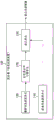
Subsequently, a first embodiment of the present invention will be explained. First, a functional configuration example of a server (information processing apparatus) 10A according to a first embodiment of the present invention will be described. Fig. 4 is a block diagram showing a functional configuration example of the server 10A according to the first embodiment of the present invention. As shown in fig. 4, the server 10A includes a calibration information acquisition unit 110, a photographic information acquisition unit 120, and a correction unit 130. First, the function of the calibration information acquisition unit 110 will be explained.
Fig. 5 shows a functional configuration example of the calibration information acquisition unit 110. As shown in fig. 5, the calibration information acquisition unit 110 includes an image acquisition unit 111, a luminance calculation unit 112, and a temperature acquisition unit 113. First, the camera 30 switches the illumination light source at the time of calibration while photographing the reference substance. Here, as the reference substance, it is desirable to use a diffuse reflection standard or the like having the same reflectance with respect to light having the wavelength of each illumination light source.
Here, let us assume the case: the camera 30 switches between respective illumination Light Sources (LEDs) of white light, red light, near-infrared light, and green light, takes images under the respective illumination Light Sources (LEDs), and supplies a total of four images to the image acquisition unit 111. In this case, the images supplied to the image acquisition unit 111 are respectively represented by pIW、pIR、pIIRAnd pIGAnd (4) showing. The image acquisition unit 111 acquires the image pI at the time of calibration from the camera 30 in this mannerW、pIR、pIIRAnd pIG. Note that the types of the illumination light sources are not limited to four types. For example, a new LED may be added as a new illumination light source other than the four illumination light sources, or an unnecessary illumination light source among the four illumination light sources may be deleted.
The luminance calculating unit 112 calculates the image pI at the time of calibration acquired by the image acquiring unit 111W、pIR、pIIRAnd pIGThe respective brightness of. Here, the luminance calculating unit 112 does not necessarily change for eachThe luminance calculation method of the illumination light source, but may be changed for each illumination light source as will be described below.
For example, in the case where the illumination light source is a white light source, the luminance calculation unit 112 may use the illuminance as the luminance of the image. On the other hand, in the case where the illumination light source is a red light source, since the signal of the red channel of RGB is dominant, the luminance calculation unit 112 desirably uses the value of the red channel signal as the luminance of the image. In the same manner, in the case where the illumination light source is a near-infrared light source, the luminance calculation unit 112 desirably uses the value of the red channel signal as the luminance of the image; and in the case where the illumination light source is a green light source, the luminance calculation unit 112 desirably uses the value of the green channel signal as the luminance of the image.
Here, the luminance of the image may represent an average value of the luminance of the entire image. For example, the luminance calculation unit 112 may calculate the image pI at the time of calibrationW、pIR、pIIRAnd pIGThe luminance average value of the respective overall images. Hereinafter, the image pI at the time of calibrationW、pIR、pIIRAnd pIGRespectively from pB to pBW、pBR、pBIRAnd pBGAnd (4) showing.
The temperature acquisition unit 113 acquires the temperature of the illumination light source at the time of calibration. For example, the temperature acquisition unit 113 acquires from a thermistor (temperature detector): the temperature of the illumination light source measured by a thermistor or the like at the timing when the image acquisition unit 111 acquires the image at the time of calibration. The thermistor may be disposed at a position capable of substantially measuring the temperature of the illumination light source (may be disposed near the illumination light source), and may be disposed inside the camera 30. In this case, the temperatures of the illumination light sources acquired by the temperature acquisition unit 113 are respectively made by pTW、pTR、pTIRAnd pTGAnd (4) showing.
Fig. 6 shows a functional configuration example of the photographic information acquisition unit 120. As shown in fig. 6, the photographic information acquisition unit 120 includes an image acquisition unit 121 and a temperature acquisition unit 122. First, at the time of image capturing, the camera 30 captures an object such as skin while switching the illumination light source.
Here, let us assume the case: the camera 30 switches between respective illumination Light Sources (LEDs) of white light, red light, near-infrared light, and green light, captures images under the respective illumination Light Sources (LEDs), and supplies a total of four images to the image acquisition unit 121. In this case, the images supplied to the image acquiring units 121 are respectively represented by cIW、cIR、cIIRAnd cIGAnd (4) showing. The image acquisition unit 121 acquires the image cI at the time of photographing from the camera 30 in this mannerW、cIR、cIIRAnd cIG。
The temperature acquisition unit 122 acquires the temperature of the illumination light source at the time of photographing. For example, the temperature acquisition unit 122 acquires from the thermistor: the temperature of the illumination light source is measured by a thermistor or the like at the timing when the image acquisition unit 121 acquires an image at the time of photographing. In this case, the temperatures of the illumination light sources acquired by the temperature acquisition unit 122 are respectively represented by cTW、cTR、cTIRAnd cTGAnd (4) showing.
Fig. 7 shows a functional configuration example of the correction unit 130. As shown in fig. 7, the correction unit 130 includes a luminance calculation unit 131 and an image correction unit 132. The luminance calculating unit 131 calculates the image at photographing cI acquired by the image acquiring unit 121 included in the photographing information acquiring unit 120W、cIR、cIIRAnd cIGThe respective luminance image of (a). Here, the luminance calculating unit 131 does not necessarily change the luminance calculating method for each illumination light source, but may also change the luminance calculating method for each illumination light source as will be described below.
For example, in the case where the illumination light source is a white light source, the luminance calculation unit 131 may use the illuminance as the luminance of the image. On the other hand, in the case where the illumination light source is a red light source, since the signal of the red channel of RGB is dominant, the luminance calculation unit 131 desirably uses the value of the red channel signal as the luminance of the image. In the same manner, in the case where the illumination light source is a near-infrared light source, the luminance calculating unit 131 desirably uses the value of the red channel signal as the luminance of the image, and in the case where the illumination light source is a green light source, the luminance calculating unit 131 desirably uses the value of the green channel signal as the luminance of the image.
Here, the luminance of the image may indicate an average value of the luminance of the entire image. For example, the luminance calculating unit 131 may calculate the image cI at the time of photographingW、cIR、cIIRAnd cIGThe luminance average value of the respective overall images. Hereinafter, image cI at the time of photographingW、cIR、cIIRAnd cIGRespectively cIBW、cIBR、cIBIRAnd cIBGAnd (4) showing.
The image correction unit 132 corrects the brightness of the image at the time of photographing based on the temperature of the illumination light source at the time of photographing, the brightness of the image at the time of photographing, and the temperature characteristic of the illumination light source (which has been prepared in advance). In this case, the image correction unit 132 may also use information at the time of the calibration. That is, the image correction unit 132 may correct the brightness of the image at the time of photographing based on the temperature of the illumination light source at the time of photographing, the temperature of the illumination light source at the time of calibration, the brightness of the image at the time of photographing, the brightness of the image at the time of calibration, and the temperature characteristic of the illumination light source.
Here, the temperature characteristics will be explained. Fig. 8 shows an example of temperature characteristics of each illumination light source (LED). Fig. 8 shows the luminous intensity or radiation intensity of each of the green light source, the red light source, and the near-infrared light source corresponding to each temperature. In this way, the temperature characteristics of each illumination light source (LED) may correspond to the luminous intensity or radiation intensity of each illumination light source (LED) corresponding to each temperature. In the example shown in fig. 8, ITmin and ITmax respectively represent a lower limit value and an upper limit value of the temperature of each illumination light source when measuring the temperature characteristic.
Further, as shown in fig. 8, the luminous intensity or radiation intensity of the illumination light source generally decreases as the temperature increases. However, as shown in fig. 8, the rate at which the luminous intensity or radiation intensity of the illumination light source decreases with an increase in temperature generally varies according to the value (DC value) of the drive current of the illumination light source (LED). Therefore, the slope of the luminous intensity (or radiation intensity) with respect to the temperature can be approximated by a polynomial using the DC value of the illumination light source (LED) according to the following formula (1).
[ mathematical formula 1]
In formula (1), the subscript i represents the type of illumination light source. The subscript i appearing in the following formula may also be considered to represent the type of illumination source. Next, the slope of the luminous intensity (or radiation intensity) of the illumination light source (LED) with respect to the DC value can be calculated according to the following formula (2).
[ mathematical formula 2]
dc_intensity_slopei=init_intensityi-(cTi-init_tempi)·delta_intensityi… (2) in formula (2), init _ temp represents the temperature (initial temperature) of the illumination light source at the time of calibration, init _ intensity represents the slope of the emission intensity at the initial temperature with respect to the DC value of the illumination light source, and delta _ intensity represents the amount of change in the slope of the emission intensity with respect to the DC value in units of each degree. Then, the luminous intensity or radiation intensity of the illumination light source (LED) with respect to an arbitrary DC value can be calculated according to the following formula (3).
[ mathematical formula 3]
intensityi=dc_intensity_slopei·led_dci…(3)
To formulate the relationship, the corrected image nI may be calculated according to the following formula (4)iLuminance at position (x, y). That is, the image correction unit 132 can correct the brightness of the image at the time of photographing based on the following formula (4).
[ mathematical formula 4]
nIi(x,y)=cIBi(x,y)-temp_int ensity_slopei·delta_tempi·pBi/(intensityi·led_numi)…(4)
In equation (4), temp _ intensity _ slope represents a slope of the luminous intensity (or radiation intensity) of the illumination light source with respect to the temperature of the illumination light source, delta _ temp represents a difference between the temperature of the illumination light source at the time of photographing and the temperature of the illumination light source at the time of calibration, intensity represents an average value of the DC values of the illumination light sources, and led _ num represents the number of illumination light sources mounted.
As described above, according to the first embodiment of the present invention, it is possible to adjust the brightness of an image using a technique of not driving and controlling an illumination light source. Therefore, the time taken for the current to stabilize is reduced compared to a technique of driving and controlling the illumination light source based on the temperature of the illumination light source.
Subsequently, referring to fig. 9, effects achieved by the first embodiment of the present invention will be explained. Fig. 9 shows an example of the relationship between the temperature of each illumination light source (thermistor temperature) before and after luminance correction on an image and the luminance of each image according to the first embodiment of the present invention. In the figure, "r" represents a case where a red light source is used as the type of the illumination light source, "nir" represents a case where a near-infrared light source is used as the type of the illumination light source, and "g" represents a case where a green light source is used as the type of the illumination light source.
In the example shown in fig. 9, "before correction" shows an example of the relationship between the thermistor temperature at the time of photographing the same target object while changing the temperature of each illumination light source and the luminance of each image before correction. On the other hand, "corrected" shows an example of the relationship between the thermistor temperature when the same target object is photographed while changing the temperature and the brightness of each image after correction. As shown in fig. 9, the luminance of the image decreases as the temperature increases before the luminance correction is performed on the image, but the decrease in the luminance of the image can be suppressed regardless of the temperature after the luminance correction is performed on the image.
Thus, the first embodiment of the present invention has been explained.
<2 > description of the second embodiment
Subsequently, a second embodiment of the present invention will be explained. The second embodiment of the present invention is different from the first embodiment of the present invention in the function of the image correction unit 132. Therefore, in the second embodiment of the present invention, the function of the image correction unit 132 will be mainly explained. Note that, in the second embodiment of the present invention, the function of the server 10B will be explained with reference to the functional configuration example of the server 10B shown in fig. 4 as appropriate.
In the first embodiment of the present invention, an example has been described in which the luminance of an image at the time of photographing is corrected using the temperature characteristics of the illumination light source. In the second embodiment of the present invention, an example will be described in which the luminance of an image at the time of photographing is corrected using the rate of change in the temperature characteristic of the illumination light source. That is, in the second embodiment of the present invention, the image correction unit 132 corrects the brightness of the image at the time of photographing based on the temperature of the illumination light source at the time of photographing, the brightness of the image at the time of photographing, and the rate of change in the temperature characteristic of the illumination light source.
Fig. 10 shows an example of the correspondence between the DC value of each illumination light source (LED) and the rate of change in luminous intensity (or radiation intensity). In fig. 10, for each of the green light source, the red light source, and the near-infrared light source, a change rate of the light emission intensity (or radiation intensity) of the illumination light source (LED) corresponding to each DC value in the case where the temperature of the illumination light source is changed from 15 ℃ to 45 ℃. As shown in fig. 10, the luminous intensity of the illumination light source (LED) varies according to the DC value of the illumination light source (LED), but when the DC value increases to some extent, the rate of change in the luminous intensity (or radiation intensity) of the illumination light source (LED) may be linearly approximated as shown in the following equation (5).
[ mathematical formula 5]
In equation (5), n represents the degree (degree), and change _ rate _ coef represents a coefficient for each degree. Further, in the case where the rate of change in the luminous intensity (or radiation intensity) of the illumination light source (LED) is linearly approximated, the value of N is "1" in formula (5). The luminance of the image corrected according to the formula (5) may be calculated using the following formula (6). That is, the image correction unit 132 can correct the brightness of the image at the time of photographing based on the following formula (6).
[ mathematical formula 6]
nIi(x,y)=cIBi(x,y)-cIBi(x,y)·(change_ratei/100)·(delta_tempi/limit_delta_tempi)…(6)
In equation (6), delta _ temp and limit _ delta _ temp represent temperature differences defined by the following equations (7) and (8), respectively.
[ mathematical formula 7]
delta_tempi=cTi-pTi…(7)
[ mathematical formula 8]
limit_delta_tempi=lTmaxi-lTmini…(8)
Thus far, the second embodiment of the present invention has been explained. Note that the correction according to any one of the first embodiment of the present invention and the second embodiment of the present invention may be applied only to all the illumination light sources of the illumination unit 31, or the correction according to one embodiment may be applied to one or some of the illumination light sources of the illumination unit 31 and the correction according to another embodiment may be applied to the remaining illumination light sources of the illumination unit 31.
For example, the correction according to the second embodiment of the present invention can be applied to an illumination light source (for example, an illumination light source of green light) that requires a high DC level because the LED light amount is small. On the other hand, the correction according to the first embodiment of the present invention can be applied to, for example, an illumination light source that does not require a high DC level because the LED light amount is large (for example, an illumination light source of red light).
Further, a correction capable of obtaining an effect similar to that of the above-described correction according to the first embodiment of the present invention may also be included in the correction according to the first embodiment of the present invention. Further, a correction capable of obtaining an effect similar to that of the above-described correction according to the second embodiment of the present invention may also be included in the correction according to the second embodiment of the present invention.
<3 > description of the third embodiment
Subsequently, a third embodiment of the present invention will be explained. Fig. 11 shows a functional configuration example of a server 10C according to the third embodiment of the present invention. As shown in fig. 11, the third embodiment of the present invention is different from the first and second embodiments of the present invention in that a melanin amount calculation unit 140 is included. Therefore, in the third embodiment of the present invention, the function of the melanin amount calculation unit 140 will be mainly described.
The melanin pigment amount calculation unit 140 calculates the amount of melanin pigment included in an object (such as skin) based on the luminance-corrected image. Here, the light absorption characteristics of melanin will be explained. Fig. 12 shows the light absorption characteristics of melanin and other components (hemoglobin and collagen). As shown in fig. 12, melanin is known to exhibit such light absorption characteristics: the values decrease from the red wavelength range to the near infrared wavelength range.
The melanin amount calculation unit 140 can calculate the amount of melanin MX using the light absorption characteristics of melanin based on the average value of the image after brightness correction under the red light source and the average value of the image after brightness correction under the near-infrared light source. Specific calculation examples of the amount of melanin MX are shown in the following formula (9).
[ mathematical formula 9]
In formula (9), AMXAnd BMXThe parameters used for calculating the amount of melanin are respectively indicated, and the upper line indicates the average value. Fig. 13 shows an example of the relationship between the temperature of the illumination light source (thermistor temperature) and the amount of melanin pigment before and after the brightness correction of the image. Equation (9) is used to calculate the amount of melanin. In the figure, "mx" indicates a case where the object to be measured is melanin.
In the example shown in fig. 13, "before correction" shows an example of the relationship between the thermistor temperature and the amount of melanin pigment before correction when the same target object is photographed while changing the temperature of each illumination light source. On the other hand, "corrected" shows an example of the relationship between the thermistor temperature and the corrected amount of melanin pigment when the same target object is photographed while changing the temperature. As shown in fig. 13, the amount of melanin increases with an increase in temperature before the image is subjected to the brightness correction, but the increase in the amount of melanin according to the temperature can be suppressed (the amount of melanin can be calculated more accurately) after the image is subjected to the brightness correction.
Note that in the above description, an example has been described in which the luminance of an image at the time of photographing is corrected by the correction unit 130. However, the brightness of the image at the time of photographing can be corrected by the melanin pigment amount calculation unit 140. In this case, the melanin amount calculation unit 140 corrects only the images for calculating the amount of melanin (in the above example, the images taken under the red light source and the near-infrared light source, respectively), and thus the amount of processing required for luminance correction can be reduced.
Thus far, the third embodiment of the present invention has been explained.
<4 > description of the fourth embodiment
Subsequently, a fourth embodiment of the present invention will be explained. Fig. 14 shows a functional configuration example of a server 10D according to the fourth embodiment of the present invention. As shown in fig. 14, the fourth embodiment of the present invention is different from the first and second embodiments of the present invention in that a red color element amount calculation unit 150 is included. Therefore, in the fourth embodiment of the present invention, the function of the red color element calculation unit 150 will be mainly described.
The red-color-amount calculating unit 150 calculates the amount of red color included in an object (such as skin) based on the luminance-corrected image. Here, the red pigment of the skin is generally derived from the hemoglobin component contained in the skin. Here, the light absorption characteristics of hemoglobin will be explained. Fig. 15 shows the light absorption characteristics of hemoglobin and other components (melanin and collagen). As shown in fig. 15, hemoglobin is known to exhibit such light absorption characteristics: the values decrease from the green wavelength range to the red wavelength range.
The red pigment amount calculation unit 150 can calculate the amount of red pigment EX using the light absorption characteristics of hemoglobin based on the average value of the image after the luminance correction under the green light source and the average value of the image after the luminance correction under the red light source. The specific calculation of the amount of the red pigment EX is shown in the following formula (10), for example.
[ mathematical formula 10]
In the formula (10), AEXAnd BEXParameters for calculating the amount of red pigment are respectively indicated, and the upper line indicates the average value. Fig. 16 shows an example of the relationship between the temperature of the illumination light source (thermistor temperature) and the amount of red pigment before and after luminance correction of an image. Equation (10) is used to calculate the amount of red pigment. In the figure, "ex" indicates a case where the object to be measured is a red pigment.
In the example shown in fig. 16, "before correction" shows an example of the relationship between the thermistor temperature and the amount of red pigment before correction when the same target object is photographed while changing the temperature of each illumination light source. On the other hand, "corrected" shows an example of the relationship between the thermistor temperature and the corrected amount of red pigment when the same target object is photographed while changing the temperature. As shown in fig. 16, the amount of red pigment increases with an increase in temperature before the image is subjected to the luminance correction, but the increase in the amount of red pigment according to the temperature can be suppressed (the amount of red pigment can be calculated more accurately) after the image is subjected to the luminance correction.
Note that in the above description, an example has been described in which the luminance of an image at the time of photographing is corrected by the correction unit 130. However, the brightness of the image at the time of photographing may be corrected by the red color element amount calculation unit 150. In this case, the red-color-amount calculating unit 150 corrects only the images for calculating the amount of red color (in the above example, the images taken under the green light source and the red light source, respectively), and thus the amount of processing required for luminance correction can be reduced.
Thus far, the fourth embodiment of the present invention has been explained. Note that in the third embodiment of the present invention, an example of calculating the amount of melanin pigment included in the subject based on the luminance-corrected image has been described, and in the fourth embodiment of the present invention, an example of calculating the amount of red pigment included in the subject based on the luminance-corrected image has been described. However, the amounts of other components included in the subject may be calculated based on the luminance-corrected image. For example, the brightness of the skin itself may be calculated based on an image subjected to brightness correction with respect to an image captured under a white light source. In this case, after the luminance correction is performed on the image, the change in the skin amount according to the temperature can be suppressed (the luminance of the skin can be calculated more accurately).
<5 > description of fifth embodiment
Subsequently, a fifth embodiment of the present invention will be explained. In the first embodiment of the present invention and the second embodiment of the present invention, an example in which the same luminance correction is performed on the entire image has been described. However, the same luminance correction is not necessarily performed for the entire image. In a fifth embodiment of the present invention, an example will be described in which correction is performed in such a manner that the contrast (contrast) of the melanin distribution is emphasized.
Fig. 17 shows a functional configuration example of a server 10E according to the fifth embodiment of the present invention. As shown in fig. 17, the fifth embodiment of the present invention is different from the first and second embodiments of the present invention in that a melanin distribution calculating unit 160 is included and the function of the correcting unit 130 is changed. Therefore, in the fifth embodiment of the present invention, the function of the melanin distribution calculating unit 160 and the function of the correcting unit 130 will be mainly explained.
The melanin distribution calculating unit 160 calculates the distribution of melanin pigment included in the subject based on the image at the time of photographing. For example, the melanin pigment distribution calculating unit 160 can calculate the distribution of melanin pigment included in the subject by applying the above formula (9) to each pixel of the image at the time of photographing (more specifically, by replacing "the average value of the image after luminance correction under red light source" and "the average value of the image after luminance correction under near-infrared light source" of the above formula (9) with "each pixel at the time of photographing under red light source" and "each pixel at the time of photographing under near-infrared light source", respectively).
Subsequently, the image correction unit 132 corrects the image at the time of photographing in such a manner as to emphasize the contrast of the melanin pigment distribution in the image at the time of photographing. For example, the image correction unit 132 can correct the image at the time of photographing in such a manner as to emphasize the contrast of the melanin pigment distribution in the image at the time of photographing according to the following formula (11) and formula (12).
[ mathematical formula 11]
[ mathematical formula 12]
In the above formula, αMXShowing the coefficient as a function of the relative amount of melanin fig. 18 shows the relative amount of melanin and the coefficient αMXExamples of relationships between. Subscript R and subscript IR attached to the coefficients indicate the cases where red light sources and near-infrared light sources are used as illumination light sources, respectively.
Subsequently, referring to fig. 19, effects achieved by the fifth embodiment of the present invention will be described. Fig. 19 shows an example of images before and after luminance correction according to the fifth embodiment of the present invention. "before correction" represents an example of an image before luminance correction, and "after correction" represents an example of an image after luminance correction. As shown in fig. 19, the display can be performed so that the user can easily recognize the presence of melanin pigment by performing correction to emphasize the contrast of the melanin pigment distribution.
Note that in the above description, an example has been described in which the luminance of an image at the time of photographing is corrected by the correction unit 130. However, the brightness of the image at the time of photographing can be corrected by the melanin pigment distribution calculating unit 160. In this case, the melanin distribution calculation unit 160 corrects only the images for calculating the amount of melanin (in the above example, the images taken under the red light source and the near-infrared light source, respectively), and thus the amount of processing required for luminance correction can be reduced.
<6 > description of sixth embodiment
Subsequently, a sixth embodiment of the present invention will be explained. In the first embodiment of the present invention and the second embodiment of the present invention, an example in which the same luminance correction is performed on the entire image has been described. However, the same luminance correction is not necessarily performed for the entire image. In the sixth embodiment of the present invention, an example will be explained in which correction is performed in such a manner that the contrast of the red color distribution is emphasized.
Fig. 20 shows a functional configuration example of a server 10F according to a sixth embodiment of the present invention. As shown in fig. 20, the sixth embodiment of the present invention is different from the first and second embodiments of the present invention in that a red color distribution calculation unit 170 is included and the function of the correction unit 130 is changed. Therefore, in the sixth embodiment of the present invention, the function of the red pigment distribution calculation unit 170 and the function of the correction unit 130 will be mainly described.
The red-color-distribution calculating unit 170 calculates a distribution of red color included in the object based on the image at the time of photographing. For example, the red-color-distribution calculating unit 170 can calculate the distribution of the red color pixels included in the subject by applying the above equation (9) to the respective pixels of the image at the time of photographing (more specifically, by replacing "the average value of the image after luminance correction under red light source" and "the average value of the image after luminance correction under green light source" of the above equation (9) with "the respective pixels at the time of photographing under red light source" and "the respective pixels at the time of photographing under green light source", respectively).
Subsequently, the image correction unit 132 corrects the image at the time of photographing in such a manner as to emphasize the contrast of the distribution of red pigments in the image at the time of photographing. For example, the image correction unit 132 can correct the image at the time of photographing in such a manner as to emphasize the contrast of the red color distribution in the image at the time of photographing according to the following formula (13) and formula (14).
[ mathematical formula 13]
[ mathematical formula 14]
In the above formula, αEXRepresenting the coefficient as a function of the relative amount of red pigment fig. 21 shows the relative amount of red pigment with the coefficient αEXExamples of relationships between. Subscript G and subscript R attached to the coefficients indicate the cases where green and red light sources are used as illumination light sources, respectively.
Subsequently, referring to fig. 22, effects achieved by the sixth embodiment of the present invention will be explained. Fig. 22 shows an example of images before and after luminance correction according to the sixth embodiment of the present invention. "before correction" represents an example of an image before luminance correction, and "after correction" represents an example of an image after luminance correction. As shown in fig. 22, correction to emphasize the contrast of the distribution of red pigments enables display so that the user can easily recognize the presence of red pigments.
Note that in the above description, an example has been described in which the luminance of an image at the time of photographing is corrected by the correction unit 130. However, the brightness of the image at the time of photographing may be corrected by the red color distribution calculating unit 170. In this case, the red-color-distribution calculating unit 170 corrects only the images for calculating the amount of red color (in the above example, the images taken under the green light source and the red light source, respectively), and thus can reduce the amount of processing required for luminance correction.
<7. hardware configuration example of information processing apparatus >
Subsequently, a hardware configuration example of the information processing apparatus 10 according to the embodiment of the present invention will be explained. Fig. 23 shows an example of the hardware configuration of the information processing apparatus 10 according to the embodiment of the present invention. However, the hardware configuration example shown in fig. 23 shows only one example of the hardware configuration of the information processing apparatus 10. Therefore, the hardware configuration of the information processing apparatus 10 is not limited to the example shown in fig. 23.
As shown in fig. 23, the information processing apparatus 10 includes a CPU (central processing unit) 901, a ROM (read only memory) 902, a RAM (random access memory) 903, a storage device 911, a drive 912, and a communication device 915.
The CPU901 functions as an arithmetic processing device and a control device, and controls the overall operation of the information processing apparatus 10 according to various programs. Further, the CPU901 may be a microprocessor. The ROM 902 stores programs used by the CPU901, calculation parameters, and the like. The RAM 903 temporarily stores programs for execution of the CPU901, parameters appropriately changing during execution, and the like. They are connected to each other via a host bus 156 constituted by a CPU bus or the like.
The memory device 911 is an example of a memory unit of the information processing apparatus 10, and is a device for storing data. For example, the storage device 911 may include a storage medium, a recording device for recording data in the storage medium, a reading device for reading out data from the storage medium, and a deletion device for deleting data recorded in the storage medium. The memory device 911 stores programs executed by the CPU901 and various data.
The drive 912 is a reader/writer for a storage medium, and is built in the information processing apparatus 10 or externally attached to the information processing apparatus 10. The drive 912 reads out information recorded in a removable storage medium (such as a magnetic disk, an optical disk, a magneto-optical disk, or a semiconductor memory) mounted in itself, and outputs the information to the RAM 903. In addition, the drive 912 can also write information to removable storage media.
The communication device 915 communicates with an external device via a network (or directly). The communication device 915 may be an interface for radio communication, and may include, for example, a communication antenna, an RF (radio frequency) circuit, and a baseband processor. Specific examples of the interface for radio communication include a communication unit such as a modem supporting a communication scheme such as CDMA (Code Division Multiple Access), W-CDMA (Wideband Code Division Multiple Access), LTE (Long Term Evolution), and Wi-fi (Wireless Fidelity) (registered trademark).
Further, the communication device 915 may be an interface for wired communication, and may include, for example, a connection terminal, a transmission line, and other circuits for communication processing. The CPU901 and the communication device 915 may be constructed on one chip, or may be provided as separate devices. Although not illustrated in fig. 23, the information processing apparatus 10 may be driven by electric power supplied from a power supply such as a rechargeable battery, for example, and the power supply may be attached to and detached from the information processing apparatus 10.
So far, the hardware configuration example of the information processing apparatus 10 according to the embodiment of the present invention has been described.
<8. conclusion >
As described above, according to an embodiment of the present invention, there is provided an information processing apparatus 10 including: a photographing information acquiring unit 120 configured to acquire an image at the time of photographing by the camera 30 and a temperature of the illumination light source at the time of photographing; and a correction unit 130 configured to correct the luminance of the image at the time of photographing or the exposure time of the camera 30 based on the temperature of the illumination light source at the time of photographing, the luminance of the image at the time of photographing, and the temperature characteristic of the illumination light source (which has been prepared in advance). According to such a configuration, the luminance of a captured image can be adjusted using a technique that does not drive and control the illumination light source.
Hereinafter, differences between the technology written in the patent document and the technology according to the embodiment of the present invention will be described in detail. First, as a first technique, there is disclosed a technique including: the temperature of the illumination light source is measured, and the measured temperature is checked against the temperature characteristics of the illumination light source, thereby driving the light source so that the light emission intensity of the illumination light source becomes optimal (for example, see patent document 1). However, in the technique written in patent document 1, since it is necessary to drive and control the illumination light source, it takes time to stabilize the current.
As a second technique, AE (Auto Exposure) is given. However, in the case of using AE, a plurality of subjects having different luminance from each other have the same luminance in a captured image. Therefore, in the case of using AE, it is difficult to obtain a captured image reflecting the accurate brightness of the object. On the other hand, according to the embodiments of the present invention, a captured image reflecting the accurate brightness of the subject can be obtained.
The preferred embodiments of the present invention have been described above with reference to the accompanying drawings, but the present invention is not limited to the above examples. Various alterations and modifications within the scope of the appended claims may be found by those skilled in the art, and it should be understood that they will of course fall within the technical scope of the present invention.
For example, in the above description, an example has been described in which the correction unit 130 corrects the luminance of an image at the time of photographing. By such correction, the brightness of the image at the time of photographing can be corrected. However, the correction unit 130 may correct the exposure time of the camera 30 instead of the brightness of the image at the time of photographing. If the exposure time of the camera 30 is corrected, the brightness of the image taken by the camera 30 whose exposure time has been corrected is corrected although the brightness itself of the image at the time of photographing is not corrected.
Further, a program for causing hardware such as a CPU, a ROM, and a RAM built in a computer to exhibit substantially the same functions as the functions of the information processing apparatus 10 described above may also be created. Further, a computer-readable recording medium on which the program is recorded is also proposed.
Further, the effects described in the present specification are merely illustrative or exemplary effects, and are not restrictive. That is, other effects apparent to those skilled in the art can be achieved from the description of the present specification in accordance with the technique of the present invention, along with or instead of the above effects.
Further, the present invention may also be configured as follows.
(1)
An information processing apparatus, comprising:
a photographic information acquisition unit configured to acquire an image at the time of photography taken by a camera and a temperature of an illumination light source at the time of photography; and
a correction unit configured to correct the luminance of the image at the time of photographing or the exposure time of the camera based on the temperature of the illumination light source at the time of photographing, the luminance of the image at the time of photographing, and a temperature characteristic of the illumination light source, the temperature characteristic having been prepared in advance.
(2)
The information processing apparatus according to (1), wherein,
the correction unit corrects the brightness of the image at the time of photographing.
(3)
The information processing apparatus according to (2), wherein,
the correction unit corrects the brightness of the image at the time of photographing based on the temperature of the illumination light source at the time of photographing, the temperature of the illumination light source at the time of calibration, the brightness of the image at the time of photographing, the brightness of the image at the time of calibration, and the temperature characteristic of the illumination light source.
(4)
The information processing apparatus according to (3), further comprising:
a calibration information acquisition unit configured to acquire a temperature of the illumination light source at the time of calibration and a brightness of an image at the time of calibration taken by the camera.
(5)
The information processing apparatus according to (3) or (4), wherein,
the brightness of the image at the time of the calibration is the brightness of the image at the time of the calibration in which the camera captures a reference substance.
(6)
The information processing apparatus according to any one of (3) to (5), wherein,
the correction unit corrects the brightness of the image at the time of photographing based on a difference between the temperature of the illumination light source at the time of photographing and the temperature of the illumination light source at the time of calibration, the brightness of the image at the time of photographing, the brightness of the image at the time of calibration, and the temperature characteristic of the illumination light source.
(7)
The information processing apparatus according to any one of (3) to (6),
the temperature characteristic of the illumination light source represents a luminous intensity or a radiation intensity of the illumination light source corresponding to a temperature of the illumination light source.
(8)
The information processing apparatus according to (7), wherein,
the temperature characteristic of the illumination light source depends on the drive current of the illumination light source, and
the correction unit corrects the brightness of the image at the time of photographing based on the temperature of the illumination light source at the time of photographing, the temperature of the illumination light source at the time of correction, the brightness of the image at the time of photographing, the brightness of the image at the time of correction, the drive current of the illumination light source, and the temperature characteristic of the illumination light source.
(9)
The information processing apparatus according to any one of (3) to (6),
the correction unit corrects the brightness of the image at the time of photographing based on the temperature of the illumination light source at the time of photographing, the brightness of the image at the time of photographing, and a rate of change in the temperature characteristic of the illumination light source.
(10)
The information processing apparatus according to any one of (1) to (9), further comprising:
a melanin pigment amount calculation unit configured to calculate an amount of melanin pigment contained in the subject based on the brightness corrected image.
(11)
The information processing apparatus according to (10), wherein,
the melanin amount calculation unit calculates the amount of melanin based on an average value of the brightness-corrected images under the red light source and an average value of the brightness-corrected images under the near-infrared light source.
(12)
The information processing apparatus according to any one of (1) to (11), further comprising:
a red-color-amount calculating unit configured to calculate an amount of red color contained in the subject based on the luminance-corrected image.
(13)
The information processing apparatus according to claim (12),
the red-color-amount calculating unit calculates the amount of the red color based on the average value of the luminance-corrected images under the red light source and the average value of the luminance-corrected images under the green light source.
(14)
The information processing apparatus according to any one of (1) to (9),
the correction unit corrects the image at the time of photographing so as to emphasize contrast of a distribution of melanin pigment in the image at the time of photographing.
(15)
The information processing apparatus according to (14), further comprising:
a melanin pigment distribution calculating unit configured to calculate a melanin pigment distribution in the image at the time of the photographing.
(16)
The information processing apparatus according to any one of (1) to (9),
the correction unit corrects the image at the time of photographing so as to emphasize a contrast of a red color amount distribution in the image at the time of photographing.
(17)
The information processing apparatus according to (16), further comprising:
a red-color-amount-distribution calculating unit configured to calculate a red-color-amount distribution in the image at the time of the photographing.
(18)
The information processing apparatus according to (1), wherein,
the correction unit corrects an exposure time of the camera.
(19)
An information processing method, comprising:
acquiring an image shot by a camera during shooting and the temperature of an illumination light source during the shooting; and is
Correcting, by a processor, the brightness of the image at the time of photographing or the exposure time of the camera based on the temperature of the illumination light source at the time of photographing, the brightness of the image at the time of photographing, and a temperature characteristic of the illumination light source, the temperature characteristic having been prepared in advance.
(20)
A program for causing a computer to function as an information processing apparatus, the information processing apparatus comprising:
a photographic information acquisition unit configured to acquire an image at the time of photography taken by a camera and a temperature of an illumination light source at the time of photography; and
a correction unit configured to correct the luminance of the image at the time of photographing or the exposure time of the camera based on the temperature of the illumination light source at the time of photographing, the luminance of the image at the time of photographing, and a temperature characteristic of the illumination light source, the temperature characteristic having been prepared in advance.
List of reference numerals
1 skin analysis system
10(10A to 10F) Server (information processing apparatus)
20 information processing terminal
30 Camera
31 illumination unit
32 pipe part
33 casing
34 lens
35 image sensor
40 Relay device
110 calibration information acquisition unit
111 image acquisition unit
112 luminance calculating unit
113 temperature acquisition unit
120 photographic information acquisition unit
121 image acquisition unit
122 temperature acquisition unit
130 correction unit
131 luminance calculating unit
132 image correction unit
140 melanin amount calculating unit
150 red pigment amount calculating unit
160 melanin distribution calculating unit
170 red pigment distribution calculating unit