CN1070726C - Water treatment device - Google Patents
Water treatment device Download PDFInfo
- Publication number
- CN1070726C CN1070726C CN95191981A CN95191981A CN1070726C CN 1070726 C CN1070726 C CN 1070726C CN 95191981 A CN95191981 A CN 95191981A CN 95191981 A CN95191981 A CN 95191981A CN 1070726 C CN1070726 C CN 1070726C
- Authority
- CN
- China
- Prior art keywords
- filter cartridge
- spring
- flux cumulating
- fanning strip
- water treatment
- Prior art date
- Legal status (The legal status is an assumption and is not a legal conclusion. Google has not performed a legal analysis and makes no representation as to the accuracy of the status listed.)
- Expired - Fee Related
Links
- XLYOFNOQVPJJNP-UHFFFAOYSA-N water Substances O XLYOFNOQVPJJNP-UHFFFAOYSA-N 0.000 title claims abstract description 88
- 230000007246 mechanism Effects 0.000 claims abstract description 108
- 230000004907 flux Effects 0.000 claims description 40
- 238000000034 method Methods 0.000 claims description 12
- 230000000694 effects Effects 0.000 claims description 9
- 230000008569 process Effects 0.000 claims description 4
- 230000000007 visual effect Effects 0.000 claims description 3
- 239000012530 fluid Substances 0.000 claims 1
- 238000004804 winding Methods 0.000 claims 1
- 206010011906 Death Diseases 0.000 abstract 1
- 210000000056 organ Anatomy 0.000 description 10
- 238000001914 filtration Methods 0.000 description 9
- 239000000126 substance Substances 0.000 description 7
- 238000005516 engineering process Methods 0.000 description 6
- 230000008859 change Effects 0.000 description 5
- 239000011159 matrix material Substances 0.000 description 4
- 238000009434 installation Methods 0.000 description 3
- 238000007789 sealing Methods 0.000 description 3
- OKTJSMMVPCPJKN-UHFFFAOYSA-N Carbon Chemical compound [C] OKTJSMMVPCPJKN-UHFFFAOYSA-N 0.000 description 2
- 238000004140 cleaning Methods 0.000 description 2
- 230000005611 electricity Effects 0.000 description 2
- 238000003780 insertion Methods 0.000 description 2
- 230000037431 insertion Effects 0.000 description 2
- 239000000463 material Substances 0.000 description 2
- 239000013618 particulate matter Substances 0.000 description 2
- 238000011045 prefiltration Methods 0.000 description 2
- 238000005406 washing Methods 0.000 description 2
- NWUYHJFMYQTDRP-UHFFFAOYSA-N 1,2-bis(ethenyl)benzene;1-ethenyl-2-ethylbenzene;styrene Chemical compound C=CC1=CC=CC=C1.CCC1=CC=CC=C1C=C.C=CC1=CC=CC=C1C=C NWUYHJFMYQTDRP-UHFFFAOYSA-N 0.000 description 1
- 238000009825 accumulation Methods 0.000 description 1
- 230000009471 action Effects 0.000 description 1
- 230000008901 benefit Effects 0.000 description 1
- 150000001875 compounds Chemical class 0.000 description 1
- 238000000354 decomposition reaction Methods 0.000 description 1
- 230000006866 deterioration Effects 0.000 description 1
- 238000010586 diagram Methods 0.000 description 1
- 239000008187 granular material Substances 0.000 description 1
- 108010036050 human cationic antimicrobial protein 57 Proteins 0.000 description 1
- 230000006872 improvement Effects 0.000 description 1
- 238000002347 injection Methods 0.000 description 1
- 239000007924 injection Substances 0.000 description 1
- 238000005342 ion exchange Methods 0.000 description 1
- 239000003456 ion exchange resin Substances 0.000 description 1
- 229920003303 ion-exchange polymer Polymers 0.000 description 1
- 238000012856 packing Methods 0.000 description 1
- 230000004044 response Effects 0.000 description 1
- 239000008399 tap water Substances 0.000 description 1
- 235000020679 tap water Nutrition 0.000 description 1
Images


Classifications
-
- C—CHEMISTRY; METALLURGY
- C02—TREATMENT OF WATER, WASTE WATER, SEWAGE, OR SLUDGE
- C02F—TREATMENT OF WATER, WASTE WATER, SEWAGE, OR SLUDGE
- C02F1/00—Treatment of water, waste water, or sewage
- C02F1/008—Control or steering systems not provided for elsewhere in subclass C02F
-
- B—PERFORMING OPERATIONS; TRANSPORTING
- B01—PHYSICAL OR CHEMICAL PROCESSES OR APPARATUS IN GENERAL
- B01D—SEPARATION
- B01D24/00—Filters comprising loose filtering material, i.e. filtering material without any binder between the individual particles or fibres thereof
- B01D24/007—Filters comprising loose filtering material, i.e. filtering material without any binder between the individual particles or fibres thereof with multiple filtering elements in series connection
- B01D24/008—Filters comprising loose filtering material, i.e. filtering material without any binder between the individual particles or fibres thereof with multiple filtering elements in series connection arranged concentrically or coaxially
-
- B—PERFORMING OPERATIONS; TRANSPORTING
- B01—PHYSICAL OR CHEMICAL PROCESSES OR APPARATUS IN GENERAL
- B01D—SEPARATION
- B01D24/00—Filters comprising loose filtering material, i.e. filtering material without any binder between the individual particles or fibres thereof
- B01D24/02—Filters comprising loose filtering material, i.e. filtering material without any binder between the individual particles or fibres thereof with the filter bed stationary during the filtration
- B01D24/04—Filters comprising loose filtering material, i.e. filtering material without any binder between the individual particles or fibres thereof with the filter bed stationary during the filtration the filtering material being clamped between pervious fixed walls
-
- B—PERFORMING OPERATIONS; TRANSPORTING
- B01—PHYSICAL OR CHEMICAL PROCESSES OR APPARATUS IN GENERAL
- B01D—SEPARATION
- B01D24/00—Filters comprising loose filtering material, i.e. filtering material without any binder between the individual particles or fibres thereof
- B01D24/48—Filters comprising loose filtering material, i.e. filtering material without any binder between the individual particles or fibres thereof integrally combined with devices for controlling the filtration
- B01D24/4861—Filters comprising loose filtering material, i.e. filtering material without any binder between the individual particles or fibres thereof integrally combined with devices for controlling the filtration by flow measuring
-
- B—PERFORMING OPERATIONS; TRANSPORTING
- B01—PHYSICAL OR CHEMICAL PROCESSES OR APPARATUS IN GENERAL
- B01D—SEPARATION
- B01D35/00—Filtering devices having features not specifically covered by groups B01D24/00 - B01D33/00, or for applications not specifically covered by groups B01D24/00 - B01D33/00; Auxiliary devices for filtration; Filter housing constructions
- B01D35/02—Filters adapted for location in special places, e.g. pipe-lines, pumps, stop-cocks
- B01D35/04—Plug, tap, or cock filters filtering elements mounted in or on a faucet
- B01D35/043—Reversible faucet filters
-
- B—PERFORMING OPERATIONS; TRANSPORTING
- B01—PHYSICAL OR CHEMICAL PROCESSES OR APPARATUS IN GENERAL
- B01D—SEPARATION
- B01D35/00—Filtering devices having features not specifically covered by groups B01D24/00 - B01D33/00, or for applications not specifically covered by groups B01D24/00 - B01D33/00; Auxiliary devices for filtration; Filter housing constructions
- B01D35/14—Safety devices specially adapted for filtration; Devices for indicating clogging
- B01D35/143—Filter condition indicators
-
- B—PERFORMING OPERATIONS; TRANSPORTING
- B01—PHYSICAL OR CHEMICAL PROCESSES OR APPARATUS IN GENERAL
- B01D—SEPARATION
- B01D35/00—Filtering devices having features not specifically covered by groups B01D24/00 - B01D33/00, or for applications not specifically covered by groups B01D24/00 - B01D33/00; Auxiliary devices for filtration; Filter housing constructions
- B01D35/14—Safety devices specially adapted for filtration; Devices for indicating clogging
- B01D35/147—Bypass or safety valves
-
- B—PERFORMING OPERATIONS; TRANSPORTING
- B01—PHYSICAL OR CHEMICAL PROCESSES OR APPARATUS IN GENERAL
- B01D—SEPARATION
- B01D35/00—Filtering devices having features not specifically covered by groups B01D24/00 - B01D33/00, or for applications not specifically covered by groups B01D24/00 - B01D33/00; Auxiliary devices for filtration; Filter housing constructions
- B01D35/14—Safety devices specially adapted for filtration; Devices for indicating clogging
- B01D35/153—Anti-leakage or anti-return valves
-
- C—CHEMISTRY; METALLURGY
- C02—TREATMENT OF WATER, WASTE WATER, SEWAGE, OR SLUDGE
- C02F—TREATMENT OF WATER, WASTE WATER, SEWAGE, OR SLUDGE
- C02F1/00—Treatment of water, waste water, or sewage
- C02F1/001—Processes for the treatment of water whereby the filtration technique is of importance
- C02F1/003—Processes for the treatment of water whereby the filtration technique is of importance using household-type filters for producing potable water, e.g. pitchers, bottles, faucet mounted devices
-
- C—CHEMISTRY; METALLURGY
- C02—TREATMENT OF WATER, WASTE WATER, SEWAGE, OR SLUDGE
- C02F—TREATMENT OF WATER, WASTE WATER, SEWAGE, OR SLUDGE
- C02F2201/00—Apparatus for treatment of water, waste water or sewage
- C02F2201/002—Construction details of the apparatus
- C02F2201/006—Cartridges
-
- C—CHEMISTRY; METALLURGY
- C02—TREATMENT OF WATER, WASTE WATER, SEWAGE, OR SLUDGE
- C02F—TREATMENT OF WATER, WASTE WATER, SEWAGE, OR SLUDGE
- C02F2209/00—Controlling or monitoring parameters in water treatment
- C02F2209/44—Time
- C02F2209/445—Filter life
Abstract
A water treatment device including an arrangement having mechanisms for mechanically totaling the volume of water filtered and for indicating when the replaceable filter cartridge has reached the end of its useful life. End-of-life indication is provided by a valve mechanism for stopping flow after a predetermined volume has been filtered. The arrangement includes a novel mechanism for resetting the flow totalization mechanism. The preferred water treatment device is faucet mounted and also includes a novel flow bypass design.
Description
The present invention relates generally to a kind of water treatment facilities, and more specifically to a kind of water treatment facilities, it has the mechanism that is used to indicate end of life, automatic closing organ, the resetting-mechanism of closing automatically and bypass mechanism.
The water treatment facilities of family expenses and other purposes is that people are known already.The mode that this device is installed in the water system can be mounted on the pipeline, also can be installed on the terminal.The former example is a kind of lower device (under-the-counter device), before water reaches tap water is filtered.The terminal installation that two kinds of common types are arranged, i.e. mesa type (contertop) and leading Setup Type.Compare with mesa type and platform lower device, design a device that is installed on the tap and need overcome some special difficulties, for example make it enough light,, make it enough compactnesses simultaneously, to avoid taking valuable channel space so that can be installed on the tap.
Water treatment facilities can adopt mechanical filter mode or chemical treatment mode to carry out water treatment.Mechanical filter is by stoping particulate matter by coming the realization water treatment.When mechanical filter unit during,, need to change the indication of filtering original paper thereby provide owing to the accumulation of particulate matter causes slowing down of current and stops near the terminal point in its service life.By contrast, when surpassing the disposal ability of chemical component, just can't provide such indication.Chemical treatment is by realizing such as absorbing (for example active medium) and ion-exchange (for example eliminating plumbous) method.Such chemical treatment is finally understood deterioration and is become invalid.Yet can't provide an indication this moment to the user, and the water of telling the user to provide no longer has been the water after effectively handling through medium.
Therefore, people have adopted various ways, in the time of can not providing the index signal that has stopped a kind of its service life because of itself characteristic with filter medium that box lunch was adopted, for the user provides above-mentioned indication.United States Patent (USP) provides an example for No. 4686037.According to this patent, adopt a prefilter to collect polluter, by the user color and a datum strip of this prefilter are compared, so that determine whether to need to change filter medium.Yet problem is this method says it is subjectivity in fact from it, therefore makes a fault unavoidably.In addition, the user is easy to forget the benchmark filter is checked, thereby thinks mistakenly still that under the situation that medium can not purify it can also operate as normal.
A kind of mode of more accurate and reliable indication end of life is that the total amount that flows through medium is added up, and automatically closes current after the water of predetermined flows through device.Although above-mentioned flux cumulating mechanism and valve-off mechanism are comparatively expensive and complicated, be considered to indicate the mode the most accurately of end of life.For example, the mechanism that the U.S. authenticates water treatment facilities, promptly the national sanitary tissue requires rated capacity is authenticated, when not adopting automatic closing organ, double dielectric capacity need be provided, and when adopting automatic closing organ, only need provide 20% additional capacity.
Known technology various electricity are disclosed with mechanical flux cumulating mechanism.United States Patent (USP) 4918426 and disclose the flux cumulating mechanism of electronic type for No. 5089114 for example.According to described patent, adopt such as pressure transmitter, to install flow velocity is measured, and then calculate total flow.When reaching predetermined quantity, start a valve in the mode of electricity, current are cut off.
United States Patent (USP) 4681677 and disclose mechanical water treatment facilities flux cumulating mechanism for No. 4689164.In mechanical system, typical method is to adopt an impeller that is driven by the water of the water treatment facilities of flowing through, and allows this impeller be connected with one group of gear, mechanically the water yield that flows through this device is carried out " accumulative total ".In addition, said gear mechanism also is connected with a valve, mechanically starts this valve after the water of predetermined quantity flows through this device, cuts off the current that flow through this device.
Yet there is some shortcoming in the automatic closing organ of known mechanical type.One of them problem is too heavy such as the mechanism of No. 4681677 employings of United States Patent (USP), it can't be installed in the device of a compactness.Another problem of known technology is to make resetting of flow integrating means and closing organ become too difficult and/or expensive.For example,, need valve and a rotating cam be separated, and discharge gear mechanism, make flux cumulating mechanism get back to 0 location of reading with manual mode with manual mode for No. 4681677 described devices of United States Patent (USP) are resetted.In No. 4698164, United States Patent (USP), a valve closure body is encased in the removable filter cartridge, when changing filter cartridge, shut off valve is connected with gear mechanism.This method is too wasted and is expensive, because shut off valve will throw away together along with filter cartridge, rather than reuses.
For the water treatment facilities that is installed on the tap, known technology is not disclosed in the technology of closing automatically when producing the end of life indication.This will be at least partially owing to will meet the flux cumulating mechanism of required compact size and closing organ and be assembled together and have certain difficulty.Its result, known devices adopted is quite incomplete end of life indicating mechanism, No. 4686037, for example above-mentioned United States Patent (USP).Known end of life indicating device is not only accurate inadequately, and owing to Valuation Standard usually requires to change filter cartridge continually, thereby also very uneconomical.
The water treatment facilities that is installed on the tap has a common characteristic, thereby promptly can carry out bypass or shunting can obtain raw water from tap for the water that flows through filter medium.These characteristics are desirable, because it can avoid the unnecessary use to filter medium, when water is not to be used to drink, but are used for when washing one's hands or washing the dishes or the like, and These characteristics makes that the user can be with the water treatment facilities bypass.
A kind of above-mentioned bypass mechanism is disclosed in No. 4686037, the United States Patent (USP).According to this patented technology, at the opposite end of installed part an independent handle has been installed, be used to control a bypass valve.What other known technologies adopted is identical mode, thereby also just has some shortcoming.Above-mentioned independent handle has unnecessarily increased the complexity and the cost of bypass mechanism.In addition, in view of the environment for use factor that is installed in the device on the tap, keep the cleaning of this device to become an important problem.An independent handle only can make the problems referred to above become more difficult, because it has increased surface area, thereby has increased the difficulty of cleaning.At last, increase the outward appearance that a handle also impairs this device, this point is even more important for some is installed in device on the tap.
In sum, the water treatment facilities of need provide a kind of compactness, low cost, being convenient to make, it has an automatic closing organ that resets easily.Also need to provide a kind of device that is installed on the tap, it is equipped with and closes automatically and simple bypass mechanism.
The invention provides a kind of water treatment facilities with removable filter cartridge.Described filter cartridge can comprise machinery or chemical filtering medium or their combination.
According to an aspect of the present invention, described water treatment facilities comprises a kind of structure, and it comprises a mechanism that mechanically water after filtering is measured, and a mechanism that sends indication when removable filter cartridge reaches the terminal point in its service life.The indication of end of life is provided by a valve mechanism, and this valve mechanism is used for stopping current when the water of predetermined quantity after filtering.This structure also comprises the mechanism that a flux cumulating mechanism resets, and this mechanism comprises a spring.Above-mentioned spring is connected with described flux cumulating mechanism and gives bias voltage by this flux cumulating mechanism, and one is used to discharge this spring so that the mechanism that flux cumulating mechanism is resetted.Described spring can adopt the various types of mechanical type springs that are applicable to this purpose, for example torsion spring, wound spring and tension type or compression-type helical spring.
According to a further aspect in the invention, described water treatment facilities comprises a kind of structure, and it comprises a shut off valve, when the current of predetermined quantity this shut off valve closure during box after filtration, thereby cuts off current.This structure also comprises the spring and the release arm that are loaded when described shut off valve is closed, be used to discharge described spring, and forces described shut off valve to be opened in the process of changing filter cartridge.
In accordance with a further aspect of the present invention, described water treatment facilities comprises a kind of structure, it comprises a mechanism that mechanically water through filtration is carried out flux cumulating, and one is indicated the mechanism of terminal point in service life by cutting off current after the water process filtration of predetermined quantity.The shut off valve of a permanent type has been installed in this device, thereby needn't have been changed it to changing filter cartridge.Said structure also comprises a mechanism that is used to make described flux cumulating mechanism to reset, and it comprises a mechanism that resets by the replacing of filter cartridge.
Resetting-mechanism of the present invention not only can be used for terminal type water treatment facilities, for example is installed in water treatment facilities and table top device on the tap, also can be installed on the pipeline, for example the platform lower device.
In accordance with a further aspect of the present invention, described water treatment facilities is a kind of device that is installed on the tap.This device that is installed on the tap comprises a mechanism, is used for after the water of predetermined quantity is filtered by this device, flows through the current of filter cartridge by cut-out, produces the indication of an end of life.
In accordance with a further aspect of the present invention, described water treatment facilities comprises a device that is installed on the tap, and it adopts a kind of bypass design of novelty.The described device that is installed on the tap comprises a housing, and filter element is housed in it, and has an entry opening and a water outlet opening.An installed part includes an inlet and an outlet, and its inlet can be installed on the tap.A valve operably is connected with housing with above-mentioned installed part, and has the first flow and second runner.Described first flow extends between above-mentioned inlet and entry opening, and second runner extends between above-mentioned entry opening and outlet.Valve body can rotate between its first and second flow locations with respect to installed part.On above-mentioned first flow locations, water is flowed into by above-mentioned inlet, by first flow, enters the entry opening of housing, through after the filter element, from the water outlet opening outflow of housing.On above-mentioned second flow locations, water is flowed into by above-mentioned inlet, by second runner, from the water outlet opening outflow of housing.Like this, by rotary shell, make water change the installed part of flowing through into by the housing of flowing through.
Above-mentioned features of novelty of the present invention and advantage clearly are expressed in subsequently claims.Yet,, embodiments of the invention are described below in conjunction with accompanying drawing for the ease of understanding the present invention.
Accompanying drawing 1 is the decomposition diagram of water treatment facilities of the present invention;
The cutaway view of the accompanying drawing 2 2-2 line that is water treatment facilities shown in the accompanying drawing 1 in the accompanying drawing 4;
The phantom of the accompanying drawing 3 3-3 line that is water treatment facilities shown in the accompanying drawing 1 in the accompanying drawing 5;
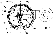
Accompanying drawing 4 is part top view cutaway views of current closing organ of the present invention, and this mechanism is positioned at 0 flow position;
Accompanying drawing 5 is part top view cutaway views of current closing organ of the present invention, and this mechanism is positioned at the position that indication has reached terminal point service life;
Accompanying drawing 6 is part top view cutaway views of current closing organ of the present invention, and this mechanism is positioned at its middle position, and resetting-mechanism of the present invention is activated;
Accompanying drawing 7 is cutaway views of bypass mechanism of the present invention, and wherein current are shunted through installed part;
The cross-sectional end view of the accompanying drawing 8 8-8 line that is bypass mechanism shown in the accompanying drawing 7 in the accompanying drawing 7.
Referring to accompanying drawing, accompanying drawing 1-8 has shown a water treatment facilities 10 that is installed on the tap, and identical parts adopt identical Reference numeral to be represented in all accompanying drawings.Although water treatment facilities 10 is mounted on the tap, its many novel features equally also can be used to be installed in device or the table top device (contertop device) on the pipeline.
Referring to attached Fig. 1 and 2, water treatment facilities 10 comprises housing 20, and it is made up of top part 22 and the cap body 24 that is installed in threadably on the top part 22.In passage 28, be provided with an O type circle, be used between top part 22 and cap body 24, forming water-stop.The filter cartridge 40 that can change is inserted among the top part 22 by the below, then cap body 24 is tightened on the top part 22, so that filter cartridge 40 is fixed among the housing 20.
Water flows through housing 20 and filter cartridge 40 in the following manner.Water enters housing 20 by the valve body 30 that is positioned at entry opening 21 places, enters among the annular space 60 between filter cartridge 40 and the housing 20, is included in the circular passage, 52 formed edge, top 62 of filter cartridge 40.Accompanying drawing 1 and 3 clearly illustrates that the most, the groove 64 that water is flowed on the tops 52 by passage 62 then, and upwards flow through cylindrical part 72,82 on lower plate 70 and the upper plate 80 respectively.Water flows out (accompanying drawing 1 shows the clearlyest) outwardly by the nozzle on the top board 90 92 then, makes it rotation so that impact the blade 102 of impeller 100.Impeller 100 closely is nested in the top board 90, shows the clearlyest to this accompanying drawing 2, makes that the gap between blade 102 and the top board 90 is as much as possible little, so that obtain maximum impeller adiabatic efficiency.Water is come out by impeller 100, flows through the outlet cylinder 94 of top board 90, and it is extended upward by second cylindrical part 84 of upper plate 80.
In normal operation when not being " closed " (be current), water is flow in the filter cartridge 40 by the inlet on the top 52 66 subsequently.Although water mainly is because the assembling mode of above-mentioned each parts and as described abovely flow like that, should be noted that water also can be full of by the lower plate 70 formed chamber 68 between the top of housing 20 part 22 that makes progress.Water will flow through successively in the process that flows through filter cartridge 40 and filter disk 43, second filter screen 55, first medium 42, first filter screen 54, second medium 44 and after-filter 56, be flowed out by the hole on the retaining ring 48 49 then.Water flows out housing 20 by water outlet opening 29 at last.Should be pointed out that described water outlet opening 29 can adopt various other structures, also can be installed on each position of housing, although preferably it is arranged on the bottom of housing 20.
Installed part 110 is used for water treatment facilities 10 is installed in a tap (not shown).Formed an inlet 113 on the configuration nut 112, and be connected with installed part main body 114 by a filter screen 116, this filter screen 116 is installed on the shoulder that disposes in the nut 112, and places the circular channel 115 of installed part main body 114 with sealing means.Connectedness 118 and connection piece 120 are inserted in the installed part main body 114 by the below, have formed outlet 119 on connectedness 118.Installed part main body 114 is stretched to valve body 30, and they are connected to each other together with sealing means by the 3rd, the 4th, the 5th O type circle 122,123,124.The 5th O type circle 124 is enclosed within on the ledge 126 of peace part main body 114, and this ledge 126 extend in the axial passage 34 of valve body 30.Axial passage 34 best tapered shapes are so that made with injection molded.
Valve body 30 can rotate between two kinds of flow locations in installed part 110, so that allow the user can be according to its hope with filter cartridge 40 bypasses.On first kind of flow locations shown in the accompanying drawing 2, water is flowed into by inlet 113.
Through the first flow 32 that forms by radial passage 33 and axial passage 34, enter into the entry opening 21 of housing 20.On second kind of flow locations shown in accompanying drawing 7 and 8, water is flowed into by inlet 113, passes through C shape second runner 36, and is flowed out by the outlet 119 of installed part 110.Those of ordinary skill in the present technique field should be understood, and the above-mentioned first flow 32 and second runner 36 also can adopt various other structures, realize changing the effect of flow direction by rotary shell 20.Although it should also be noted that to require valve body 30 is connected on the housing 20 securely, also not necessarily need be as being molded as a whole in the top part 22 that allows valve body 30 with housing 20 shown in the most preferred embodiment.
In the most preferred embodiment of flux cumulating mechanism 130, impeller 100 is meshed with a plurality of gears 132, and the latter is meshed with a rotation fanning strip 140 again.Should be pointed out that impeller 100 not necessarily will be meshed with first gear 134, fanning strip 140 also not necessarily will be meshed with final gear 136.Gear train 132 is meshing with each other successively, and in most preferred embodiment, each gear has 10/1 gearratio.Impeller 100 and two gears 132 are installed on first 138, and remaining 3 gear 132 comprises that first gear 134 and final gear 136 are installed on second 139.Top part 22 by housing 20 places on its installation site from the top with axle 138,139.With first 138 hole that is inserted on the upper plate 80, place its installation site with second 139 from the below by final gear 136, this by and the bossing 86 of located upper plate 80 on.
Shown in attached Figure 4 and 5, be meshed with the gear teeth 142 of fanning strip 140 by the gear teeth 137 final gear 136, make final gear 136 be connected with fanning strip 140.Like this, when impeller 100 rotations, gear 132 will rotate thereupon, makes fanning strip 140 be driven rotation by the gear teeth 137, thereby increases the aggregate-value of the water of the filter cartridge 40 of flowing through.
The most preferred embodiment of valve-off mechanism 150 comprises the entry opening 66 of ball 152 and filter cartridge 40, and above-mentioned ball 150 is fixing and with rotation therewith by fanning strip 140.Shown in accompanying drawing 2 and 4, valve-off mechanism 150 starts since 0 accumulative total position.After flux cumulating mechanism 130 turns to fanning strip 140 when stopping flow locations, shown in accompanying drawing 3 and 5, ball 152 will be located on the entry opening 66 of filter cartridge 40, and this entry opening 66 is formed by the bossing 51 at the top 52 of passing lower plate 70.Those of ordinary skill in the present technique field can be understood, and can also adopt other various suitable mechanical type valve mechanisms.
Resetting-mechanism 160 comprises spring 162, and it is connected with fanning strip 140, and is reeled by this plate when fanning strip 140 rotations.Although should be pointed out that what adopt is helical spring 162 in most preferred embodiment, also can adopt the structure of coming biasing spring by flux cumulating mechanism of the spring of other types described below and other.When the spring 162 in the needs release most preferred embodiment, allow the gear teeth 137 and the gear teeth 142 of fanning strip 140 break away from engagement in the radial direction, thereby make fanning strip 140 under the effect of spring 162, forward 0 aggregate-value position to towards circling round.Also can reach same effect by allowing the gear teeth 142 and the gear teeth 137 break away from engagement in the axial direction.
In most preferred embodiment, the transverse movement by slide block 164 comes retracting spring 162, and this slide block 164 has played the effect of a release arm.Slide block 164 comprises that a vertical stretch divides 165, and fanning strip 140 and spring 162 are installed on this extension in the mode that can rotate.Spring 162 comprises two levers 163, and they are extended outwardly by the opposite end of spring 162, and one of them termination 163 leans against on the retainer 144 on the fanning strip 140, and another termination 163 then leans against on the fixed stop 74 on the lower plate 70.Because spring 162 can either play the effect that stops sector rack 140 to rotate, also can play the effect that stops slide block 164 generation transverse movements, therefore in this structure, spring 162 can play fanning strip 140 and the slide block 164 rotating effects of making simultaneously.By the guiding piece on lower plate 70 76, make slide block 164 be limited to and move along this guiding piece.As shown in Figure 1, by inserting screw 88, the parts between upper plate 80 and the lower plate 70 are assembled together by the below.
In above-mentioned most preferred embodiment, slide block 164 is along with the insertion of filter cartridge 40 and taking-up and produce slip.Should be pointed out that slide block 164 also can various other modes move, for example by flux cumulating mechanism 130 being resetted by next button.Flux cumulating mechanism 130 also can adopt the various mechanisms that other can respond the replacing action of filter cartridge 40 to be resetted.For example, can design a kind of like this mechanism, when inserting filter cartridge 40, can make final gear 136 from axial direction, break away from engagement, perhaps under the situation of not using spring 164, make fanning strip 140 break away from engagement and rotation with fanning strip 140.
In most preferred embodiment, a cam 53 drives slide block 164 and produces slip, and this cam 53 is axially extended by the top 52 of filter cartridge 40.In the time of among filter cartridge 40 axially is inserted into housing 20, this cam 53 passes the opening 78 on the lower plate 70, leans against on the cam guidance surface 166 on the slide block 164, is used to make slide block 164 to produce transverse movement.
Except providing when the end of life one to flow and stop the indication, a continuous visual indication also is provided in most preferred embodiment, be used to indicate also remaining how many operational times of removable filter cartridge 40.This function is to provide a coloured screen 146 to realize by the end at fanning strip 140, when fanning strip 140 rotations, can watch this screen by a camera lens 170.As shown in Figure 1, above-mentioned camera lens 170 is inserted in the groove 23 of top part 22 of housing 20, and seals by packing ring 171.
In most preferred embodiment, filter cartridge 40 is equipped with two kinds of chemical filtering media, and wherein first kind of medium 42 adopts and be suitable for removing plumbous ion exchange resin, and second kind of medium 44 (GAC) made by " granule activated carbon ".Within the scope of the present invention, also can adopt the various compound modes of mechanical filter media or other chemical filtering media.
In the most preferred embodiment of filter cartridge 40, medium 42,44 is encapsulated by matrix 46, O type circle locator 48 and top 52, wherein O type circle locator 48 is installed in one of matrix 46 outstanding cylindrical part 50 inwardly with friction fit, and the inboard on top 52 and matrix 46 tops forms frictional fit.Matrix 46 comprises shoulder 47, and it is by cap spare 24 supporting, so that filter cartridge 40 is pushed among the housing 20 up.Locator 48 is with second O type circle 27 fix in position, so that form sealing between the ledge inwardly 25 of locator 48, cylindrical part 50 and cap spare 24.Water is discharged filter cartridge 40 by the hole in the locator 48 49.
In filter cartridge 40, filter medium 42,44 (not showing in accompanying drawing 1) separates each other by first filter screen 54, second filter screen 55 is isolated from each other first filter medium 42 and comes with filter disk 43, described filter disk 43 is fixed between the top 52 and second filter screen 55.Filter disk 43 is made by white filter paper, its objective is to the user provides a kind of visual indication, whether is carrying out its function so that determine filter cartridge 40, and is indicating whether to adopt a kind of specific filter cartridge.In most preferred embodiment, top 52 is transparent, so whether the user can see having assembled on the described filter disk 43 and be filtered material, thereby confirms to have adopted filter cartridge.U-shaped post filter 56 is projected upwards by cylindrical part 50, is used to prevent from GAC is gone out, and post filter cap 57 precoat filters 56 so that water is directed to the bottom of filter cartridge 46, guarantee that whole second medium 44 all is utilized.
Should be pointed out that above-mentioned most preferred embodiment only is the character of giving an example, the present invention is not limited to above-mentioned most preferred embodiment.According to the present invention, within the scope of following claim, can also make the arrangement of improvement, especially shape on all details, size, parts, material that parts adopt or the like to the present invention.
Claims (17)
1. mechanism that adopts in water treatment facilities comprises:
A. removable filter cartridge;
B. flux cumulating mechanism, the water yield of the described replaceable filter cartridge that is used for mechanically totally flowing through;
C. be used to indicate the mechanism of described replaceable filter cartridge end of life, comprise shut off valve, be used for after the described flux cumulating mechanism water yield totally reaches predetermined quantity, stopping water and flowing through described filter cartridge;
D. be used for described flux cumulating mechanism is reset to the mechanism of 0 location of reading, comprise:
I. be connected with described flux cumulating mechanism and by the spring of this flux cumulating mechanism bias voltage;
II. be used to discharge the mechanism of described spring, so that flux cumulating mechanism is resetted.
2. mechanism as claimed in claim 1 is characterized in that, described end of life indicating mechanism further comprises the vision component that is used to indicate end of life.
3. mechanism as claimed in claim 1 is characterized in that, described flux cumulating mechanism comprises:
A. impeller that drives by the water that flows through this water treatment facilities;
B. gear mechanism that is connected with described impeller, the rotation of described impeller make a plurality of rotations of meshed gears each other, and this gear comprises first gear and final gear that is connected with described impeller;
C. rotation fanning strip that is connected with described last gear, this fanning strip is connected with described spring, makes described spring produce bias voltage when described final gear drives this fanning strip rotation.
4. mechanism as claimed in claim 3 is characterized in that, described spring discharge mechanism comprises and is used to make described fanning strip to break away from the mechanism that is connected with final gear.
5. mechanism as claimed in claim 4, it is characterized in that, described spring discharge mechanism further comprises a slide block, described fanning strip pivotally is connected with this slide block, described slide block can slide, and is connected so that fanning strip is broken away from final gear, thereby discharges described spring, allow fanning strip under the effect of spring, get back to 0 flow position, described flux cumulating mechanism is resetted.
6. mechanism as claimed in claim 5 is characterized in that described slide block comprises a driven surface of cam, slides by allowing a cam contact with described driven surface to make slide block to produce, so that described flux cumulating mechanism is resetted.
7. mechanism as claimed in claim 6 is characterized in that, described cam is gone out by a distal process of described removable filter cartridge, when making among filter cartridge suitably inserts water treatment facilities, described flux cumulating mechanism is resetted.
8. mechanism as claimed in claim 5, it is characterized in that, described spring is a winding screw, its two ends have the termination of stretching out, it is characterized in that, a termination leans against on first retainer of described fanning strip, and another termination leans against on the second fixing retainer, and the elastic force of this spring makes described slide block get back to the position that it does not slide.
9. mechanism as claimed in claim 8 is characterized in that, described spring and fanning strip all pivotally are installed on the outstanding position of described slide block.
10. mechanism as claimed in claim 3, it is characterized in that, described final gear comprises a pinion, the a plurality of gear teeth of described fanning strip by being used for being meshed with described pinion directly are connected with described final gear, and this pinion makes fanning strip produce rotation, to realize flux cumulating, this pinion can break away from the engagement with described a plurality of gear teeth, so that retracting spring, mechanism resets with flux cumulating.
11. mechanism as claimed in claim 3 is characterized in that, described shut off valve comprises:
A. one by the described fanning strip location and the ball that can rotate thereupon;
B. described replaceable filter cartridge fluid intake is used to admit this ball, so that cut off the current through this opening.
12. mechanism as claimed in claim 1, it is characterized in that, described resetting-mechanism comprises a spring, be connected with described flux cumulating mechanism and under the effect of this flux cumulating mechanism, produce bias voltage, in the time of among filter cartridge suitably being inserted into water treatment facilities, discharge this spring, so that described flux cumulating mechanism is resetted.
13. mechanism as claimed in claim 1 is characterized in that, described filter cartridge more converting mechanism comprises one by the outstanding cam of described replaceable filter cartridge, when inserting filter cartridge, discharges described spring by this cam, so that flux cumulating mechanism is resetted.
14. a water treatment facilities that is installed on the tap comprises:
(a) tap installed part;
(b) housing of an extension, this housing have the removable filter cartridge that is arranged at wherein; With
(c) flux cumulating mechanism, the water yield that its accumulative total has flow through from described filter cartridge;
(d) end of life indicating device, be used for when described filter cartridge has reached its useful life, indicating, this device comprises a valve, is used for stopping water after flowing through and flowing through described filter cartridge utilizing described flux cumulating mechanism to measure the water that scheduled volume is arranged.
15. water treatment facilities as claimed in claim 14 is characterized in that, described flux cumulating mechanism is a mechanical integrating instrument.
16. water treatment facilities as claimed in claim 15 is characterized in that, described mechanical integrating instrument comprises the gear of an impeller and many interconnection.
17. water treatment facilities as claimed in claim 14 is characterized in that, also comprises one and the cooperative visual detector of described flux cumulating mechanism, is used for providing the vision indication in remaining service life of a kind of described removable filter cartridge.
Applications Claiming Priority (2)
| Application Number | Priority Date | Filing Date | Title |
|---|---|---|---|
| US08/207,380 | 1994-03-08 | ||
| US08/207,380 US5527451A (en) | 1994-03-08 | 1994-03-08 | Water treatment device with volume totalization valve |
Publications (2)
| Publication Number | Publication Date |
|---|---|
| CN1143332A CN1143332A (en) | 1997-02-19 |
| CN1070726C true CN1070726C (en) | 2001-09-12 |
Family
ID=22770306
Family Applications (1)
| Application Number | Title | Priority Date | Filing Date |
|---|---|---|---|
| CN95191981A Expired - Fee Related CN1070726C (en) | 1994-03-08 | 1995-03-06 | Water treatment device |
Country Status (9)
| Country | Link |
|---|---|
| US (2) | US5527451A (en) |
| EP (2) | EP0749346B1 (en) |
| JP (1) | JP3677043B2 (en) |
| KR (1) | KR100358713B1 (en) |
| CN (1) | CN1070726C (en) |
| AU (1) | AU1982795A (en) |
| DE (2) | DE69533177T2 (en) |
| TW (1) | TW294605B (en) |
| WO (1) | WO1995024256A1 (en) |
Families Citing this family (109)
| Publication number | Priority date | Publication date | Assignee | Title |
|---|---|---|---|---|
| US5017286A (en) * | 1990-03-05 | 1991-05-21 | Heiligman Randy B | Faucet-mounted water filter with wall inlet and annular chamber |
| US5536394A (en) * | 1994-11-17 | 1996-07-16 | Recovery Engineering, Inc. | End of life mechanism for water treatment cartridge |
| US5549010A (en) * | 1995-01-13 | 1996-08-27 | Ziba Design, Inc. | Readily serviceable ancillary fluid filtration system having visual flow rate indicator and quick-release fluid hose fitting |
| US5622618A (en) * | 1995-05-31 | 1997-04-22 | Brane; Earl P. | Apparatus for monitoring cumulative flow of fluid through a filter medium |
| US7400267B1 (en) | 1995-06-08 | 2008-07-15 | Western Strategic Products, Llc | Methods for determining need for treating a vehicle travel surface |
| US6938829B2 (en) * | 1996-06-07 | 2005-09-06 | John A. Doherty | Apparatus and system for synchronized application of one or more materials to a surface from a vehicle and control of a vehicle mounted variable position snow removal device |
| US7839301B2 (en) * | 1995-06-08 | 2010-11-23 | Western Strategic Products, Llc | Surface condition sensing and treatment systems, and associated methods |
| US6535141B1 (en) | 1996-06-07 | 2003-03-18 | John A. Doherty | Vehicle mounted travel surface and weather condition monitoring system |
| TW479675U (en) * | 1996-02-01 | 2002-03-11 | Graco Inc | Preset fluid dispensing meter |
| US5871639A (en) * | 1996-03-11 | 1999-02-16 | Hsu; Chao Fou | Impurity filtration system for drinking water and monitoring device therefor |
| US5814212A (en) * | 1996-03-11 | 1998-09-29 | Hsu; Chao Fou | Monitoring process and device for an activated carbon filtration system of drinking water |
| US5876610A (en) * | 1997-03-19 | 1999-03-02 | Clack Corporation | Method and apparatus for monitoring liquid flow through an enclosed stream |
| US5873995A (en) * | 1997-05-06 | 1999-02-23 | The Clorox Company | End-of-life indicator for water treatment device |
| US5888381A (en) * | 1997-05-16 | 1999-03-30 | United States Filter Corporation | Water filter with pressure actuated flow monitor |
| US6149801A (en) | 1997-08-08 | 2000-11-21 | Water Pik, Inc,. | Water treatment device with volumetric monitoring features |
| US6179130B1 (en) | 1997-08-08 | 2001-01-30 | Emhart Inc. | Faucet spout assembly |
| US5935426A (en) | 1997-08-08 | 1999-08-10 | Teledyne Industries, Inc., A California Corporation | Water treatment device with volumetric and time monitoring features |
| US6162219A (en) * | 1997-10-21 | 2000-12-19 | Akzo Nobel N.V. | Electrode |
| US6312589B1 (en) | 1997-12-23 | 2001-11-06 | The Coca-Cola Company | Apparatus arranged to provide controllable water treatment customized to the conditions of water supplied to a beverage dispenser |
| US5997734A (en) * | 1998-01-16 | 1999-12-07 | American Standard, Inc. | Flow totalization, reset, and restriction mechanism for use in indicating the end of a treatment cartridge useful life |
| US5976362A (en) * | 1998-04-01 | 1999-11-02 | The Clorox Company | Faucet mounted water filter |
| CA2318636C (en) * | 1998-01-21 | 2008-05-13 | The Clorox Company | Faucet mounted water filter |
| US5993648A (en) * | 1998-03-17 | 1999-11-30 | American Standard, Inc. | Water filtration device with a water fountain outlet and a faucet outlet with flow viewing apparatus |
| US6033557A (en) * | 1998-06-02 | 2000-03-07 | Gebhard; Albert W. | Filter use limitation device for liquid containers |
| DE19846380A1 (en) * | 1998-10-08 | 2000-04-13 | F & L Handels Gmbh | Air bleed filter for water supply has hydrophobic membrane requiring no pressure compensating vessel with a high pressure bleed valve |
| US6251274B1 (en) | 1999-03-16 | 2001-06-26 | Envirogard Products Limited | Faucet attachment for treating water |
| US6368503B1 (en) | 1999-06-29 | 2002-04-09 | Kimberly-Clark Worldwide, Inc. | Filtered fluid dispensing system |
| US6212959B1 (en) | 1999-08-03 | 2001-04-10 | Craig R. Perkins | Hydration insuring system comprising liquid-flow meter |
| US6395678B1 (en) | 1999-09-01 | 2002-05-28 | Aero-Terra-Aqua Technologies Corporation | Bead and process for removing dissolved metal contaminants |
| US6457589B1 (en) * | 2000-02-24 | 2002-10-01 | Kimberly-Clark Worldwide, Inc. | Fluid filtration and dispensing system |
| US6355177B2 (en) | 2000-03-07 | 2002-03-12 | Maytag Corporation | Water filter cartridge replacement system for a refrigerator |
| US6428708B1 (en) | 2000-03-07 | 2002-08-06 | Kinetico Incorporated | Filter apparatus and method |
| US6328881B1 (en) * | 2000-03-08 | 2001-12-11 | Barnstead Thermolyne Corporation | Water purification system and method including dispensed volume sensing and control |
| US6571960B2 (en) | 2000-05-01 | 2003-06-03 | Kimberly-Clark Worldwide, Inc. | Faucet-mounted water filtration device |
| AU2001263691A1 (en) * | 2000-06-05 | 2001-12-17 | Hb Innovation Ltd. | Fluid flow meter system |
| US6881333B2 (en) | 2001-03-26 | 2005-04-19 | Osaka Gas Chemicals Co., Ltd. | Water purifier filtration portion, water purifier main body, and water purifier including the both |
| US6797201B2 (en) * | 2001-04-20 | 2004-09-28 | Procaps S.A. | Multicolor gelatin ribbons and manufacture of soft gelatin products |
| US7614507B2 (en) | 2001-08-23 | 2009-11-10 | Pur Water Purification Products Inc. | Water filter materials, water filters and kits containing particles coated with cationic polymer and processes for using the same |
| KR100777951B1 (en) * | 2001-08-23 | 2007-11-28 | 더 프록터 앤드 갬블 캄파니 | Water filter materials, corresponding water filters and processes for using the same |
| US7615152B2 (en) | 2001-08-23 | 2009-11-10 | Pur Water Purification Products, Inc. | Water filter device |
| US20050279696A1 (en) * | 2001-08-23 | 2005-12-22 | Bahm Jeannine R | Water filter materials and water filters containing a mixture of microporous and mesoporous carbon particles |
| US20030217967A1 (en) * | 2001-08-23 | 2003-11-27 | The Procter & Gamble Company | Processes for manufacturing water filter materials and water filters |
| US7614508B2 (en) * | 2001-08-23 | 2009-11-10 | Pur Water Purification Products Inc. | Water filter materials, water filters and kits containing silver coated particles and processes for using the same |
| MXPA04003145A (en) * | 2001-10-05 | 2004-07-27 | Unilever Nv | Filter condition indicator. |
| DE10216847B4 (en) * | 2002-04-16 | 2007-09-20 | Water-Planet Gmbh | Filter device and filter device |
| US7258781B2 (en) * | 2002-09-09 | 2007-08-21 | Clarity Filters Llc | Single-use long-life faucet-mounted water filtration devices |
| US7252757B2 (en) * | 2002-09-09 | 2007-08-07 | Clarity Filters Llc | Faucet-mounted water filtration device including gate position sensor |
| US6860988B2 (en) * | 2002-12-23 | 2005-03-01 | Envirogard Products Ltd. | Fluid filtration system with fluid flow meter |
| US6863825B2 (en) | 2003-01-29 | 2005-03-08 | Union Oil Company Of California | Process for removing arsenic from aqueous streams |
| USD494654S1 (en) | 2003-04-25 | 2004-08-17 | Procter & Gamble Co. | Fluidic cartridge fittings |
| USD492753S1 (en) | 2003-04-25 | 2004-07-06 | Procter & Gamble | Fluidic cartridge end piece |
| US7150829B2 (en) * | 2003-08-28 | 2006-12-19 | Pur Water Purification Products, Inc. | Water treatment cartridges and processes related thereto |
| US7316323B2 (en) * | 2004-05-06 | 2008-01-08 | The Procter & Gamble Company | Filters having improved permeability and virus removal capabilities |
| US8556127B2 (en) | 2004-05-24 | 2013-10-15 | Pur Water Purification Products, Inc. | Additive dispensing system for a refrigerator |
| US8893927B2 (en) | 2004-05-24 | 2014-11-25 | Pur Water Purification Products, Inc. | Cartridge for an additive dispensing system |
| US20050258082A1 (en) * | 2004-05-24 | 2005-11-24 | Lund Mark T | Additive dispensing system and water filtration system |
| US7670479B2 (en) * | 2004-05-24 | 2010-03-02 | PUR Water Purification, Inc. | Fluid container having an additive dispensing system |
| DE102004029634A1 (en) * | 2004-06-18 | 2006-01-26 | Aqua Carat Gmbh Ig | Connector for a water treatment device to a faucet |
| US20050279676A1 (en) * | 2004-06-21 | 2005-12-22 | Izzy Zuhair A | Fluid filter assembly for a dispensing faucet |
| US9601015B2 (en) | 2005-02-25 | 2017-03-21 | Concaten, Inc. | Maintenance decision support system and method for vehicular and roadside applications |
| US7355509B2 (en) | 2005-02-25 | 2008-04-08 | Iwapi Inc. | Smart modem device for vehicular and roadside applications |
| DE102005011763A1 (en) | 2005-03-11 | 2006-09-14 | Aqua Carat Gmbh | Water tap filter has two chambers connected in series or parallel and packed with suitable filtration agents |
| AU2006232547A1 (en) * | 2005-04-01 | 2006-10-12 | Applica Consumer Products, Inc. | Water filtration system with improved performance |
| US7537695B2 (en) * | 2005-10-07 | 2009-05-26 | Pur Water Purification Products, Inc. | Water filter incorporating activated carbon particles with surface-grown carbon nanofilaments |
| US7517451B2 (en) * | 2006-01-30 | 2009-04-14 | Chih Chou Liu | Filter for drinking water |
| US20070215531A1 (en) | 2006-03-17 | 2007-09-20 | Andreas Wawrla | Water-treatment appliance |
| USD629487S1 (en) | 2008-04-17 | 2010-12-21 | The Procter & Gamble Company | Connector for a faucet mounted water filter |
| USD629865S1 (en) | 2008-04-17 | 2010-12-28 | The Procter & Gambple Company | Connector for a faucet mounted water filter |
| US7568874B2 (en) * | 2006-06-02 | 2009-08-04 | Pur Water Purification Products, Inc. | Nut for attaching two devices and method for providing the same |
| MX2009003790A (en) * | 2006-10-08 | 2011-03-03 | Fluid filter monitoring device. | |
| USD586880S1 (en) | 2006-11-17 | 2009-02-17 | Pur Water Purification Products Inc. | Faucet mount housing |
| USD592729S1 (en) | 2006-11-17 | 2009-05-19 | Pur Water Purification Products, Inc. | Dispenser cartridge |
| US8066874B2 (en) | 2006-12-28 | 2011-11-29 | Molycorp Minerals, Llc | Apparatus for treating a flow of an aqueous solution containing arsenic |
| WO2008091845A1 (en) * | 2007-01-22 | 2008-07-31 | Ecowater Systems Llc | A water treatment system and process for a variable water flow rate and filter life monitoring algorithm and system |
| US9864957B2 (en) | 2007-06-29 | 2018-01-09 | Concaten, Inc. | Information delivery and maintenance system for dynamically generated and updated data pertaining to road maintenance vehicles and other related information |
| US8275522B1 (en) | 2007-06-29 | 2012-09-25 | Concaten, Inc. | Information delivery and maintenance system for dynamically generated and updated data pertaining to road maintenance vehicles and other related information |
| CN101795977B (en) | 2007-09-05 | 2014-06-11 | Pur水纯化产品公司 | Apparatus and methods for faucet-mounted water filtration systems |
| US8252087B2 (en) | 2007-10-31 | 2012-08-28 | Molycorp Minerals, Llc | Process and apparatus for treating a gas containing a contaminant |
| US8349764B2 (en) | 2007-10-31 | 2013-01-08 | Molycorp Minerals, Llc | Composition for treating a fluid |
| US20090107919A1 (en) * | 2007-10-31 | 2009-04-30 | Chevron U.S.A. Inc. | Apparatus and process for treating an aqueous solution containing chemical contaminants |
| WO2009088946A1 (en) | 2008-01-03 | 2009-07-16 | Iwapi, Inc. | Integrated rail efficiency and safety support system |
| EP2128515A1 (en) * | 2008-05-30 | 2009-12-02 | Koninklijke Philips Electronics N.V. | A water appliance having a flow control unit and a filter assembly |
| US8940163B2 (en) * | 2008-07-21 | 2015-01-27 | 3M Innovative Properties Company | Apparatus for dispersing additive into a fluid stream |
| SG10201403779RA (en) | 2009-09-09 | 2014-10-30 | Strauss Water Ltd | Liquid filter device |
| US8902081B2 (en) | 2010-06-02 | 2014-12-02 | Concaten, Inc. | Distributed maintenance decision and support system and method |
| TW201204454A (en) * | 2010-07-20 | 2012-02-01 | Zheng-Xiong Chen | Filter cartridge structure |
| USD637691S1 (en) | 2010-08-18 | 2011-05-10 | The Procter & Gamble Company | Connector for a faucet mounted water filter |
| USD637693S1 (en) | 2010-08-18 | 2011-05-10 | The Procter & Gamble Company | Connector for a faucet mounted water filter |
| USD637690S1 (en) | 2010-08-18 | 2011-05-10 | The Procter & Gamble Company | Connector for a faucet mounted water filter |
| DE102010041112A1 (en) * | 2010-09-21 | 2012-03-22 | Robert Bosch Gmbh | Flow meter for a liquid container and method for monitoring the hydration of a patient |
| US9233863B2 (en) | 2011-04-13 | 2016-01-12 | Molycorp Minerals, Llc | Rare earth removal of hydrated and hydroxyl species |
| WO2012177850A1 (en) * | 2011-06-21 | 2012-12-27 | Kinetico Incorporated | Water treatment system |
| US8870083B2 (en) | 2012-02-27 | 2014-10-28 | L&P Property Management Company | Mattress age indicator |
| US9257057B2 (en) | 2012-02-27 | 2016-02-09 | L&P Property Management Company | Bedding product with age indicator |
| US8939379B2 (en) | 2012-02-27 | 2015-01-27 | L&P Property Management Company | Mattress with mattress age indicator |
| US9359224B2 (en) | 2012-11-26 | 2016-06-07 | Whirlpool Corporation | Filter unit with flow regulator |
| MX370462B (en) | 2014-03-07 | 2019-12-13 | Secure Natural Resources Llc | Cerium (iv) oxide with exceptional arsenic removal properties. |
| MX2016016535A (en) | 2014-06-20 | 2017-05-01 | Unilever Nv | A metering device for an auto-shut off assembly. |
| EP3015431A1 (en) * | 2014-10-31 | 2016-05-04 | Brita GmbH | Mounting for a fluid treatment device and fluid treatment system |
| US9670076B2 (en) * | 2015-01-12 | 2017-06-06 | Pasupathicoil Ramaswamy Soundar Rajan | Water filtration system having selectively configurable filtration capabilities |
| ES2807275T3 (en) | 2015-03-23 | 2021-02-22 | Strauss Water Ltd | Water filter and assembly of the same |
| US10048242B2 (en) * | 2015-06-07 | 2018-08-14 | Shenzhen Yimu Technology Co., Ltd. | Inline water contaminant detector |
| US10525387B2 (en) | 2017-04-06 | 2020-01-07 | Whirlpool Corporation | Filter cartridge |
| US10288466B2 (en) | 2017-06-30 | 2019-05-14 | Sentry Equipment Corp. | Flow totalizer |
| US10584040B2 (en) | 2017-10-06 | 2020-03-10 | Whirlpool Corporation | Filter cartridge |
| US11219298B2 (en) | 2017-11-10 | 2022-01-11 | Aqua Fix USA, Inc. | Squeezable hybrid water bottle with integrated filter |
| US10702046B2 (en) | 2017-11-10 | 2020-07-07 | Aqua Fix USA, Inc. | Squeezable hybrid water bottle with integrated filter and method of forming the same |
| CN108793281B (en) * | 2018-06-23 | 2021-05-11 | 陈裕娟 | Water purifying device |
| WO2020167717A1 (en) * | 2019-02-12 | 2020-08-20 | As America, Inc. | Faucet with integrated water filter |
Citations (2)
| Publication number | Priority date | Publication date | Assignee | Title |
|---|---|---|---|---|
| US4769135A (en) * | 1987-03-02 | 1988-09-06 | Culligan International Company | Automatic metering system |
| US4772386A (en) * | 1986-05-30 | 1988-09-20 | Autotrol Corporation | Filter with liquid meter |
Family Cites Families (20)
| Publication number | Priority date | Publication date | Assignee | Title |
|---|---|---|---|---|
| US1008849A (en) * | 1910-12-31 | 1911-11-14 | William C Moore | Fluid-meter faucet. |
| US3762440A (en) * | 1971-12-21 | 1973-10-02 | R Bryant | Metered water faucet |
| US4172796A (en) * | 1975-09-29 | 1979-10-30 | Teledyne Industries, Inc. | Water purifier apparatus |
| US4681677A (en) * | 1978-02-17 | 1987-07-21 | Olin Corporation | Water processor having automatic shutoff and bypass means |
| DE3105677C2 (en) * | 1981-02-17 | 1984-08-02 | Standard Meßgerätefabrik GmbH, 4760 Werl | Filters for liquids, in particular water filters for the supply of drinking water |
| US4379053A (en) * | 1981-06-12 | 1983-04-05 | Brane Earl P | Filter bypass valve assembly |
| US4489616A (en) * | 1983-05-16 | 1984-12-25 | Priddy Jerry L | Digital fluid flow meter |
| US4885081A (en) * | 1985-02-19 | 1989-12-05 | Aquest, Inc. | Drinking water delivery system with purity indicator |
| US4686037A (en) * | 1985-03-27 | 1987-08-11 | Teledyne Industries, Inc. | Water filter apparatus |
| US4770768A (en) * | 1985-03-27 | 1988-09-13 | Teledyne Industries, Inc. | Water filter apparatus and aerator assembly |
| US4698164A (en) * | 1985-07-29 | 1987-10-06 | Kinetico, Inc. | Filter apparatus |
| US4918426A (en) * | 1988-05-02 | 1990-04-17 | Amway Corporation | Method and apparatus for sensing fluid flow volume to indicate end of filter life |
| US5089144B1 (en) * | 1989-12-08 | 1996-11-12 | Nartron Corp | Filter condition indicator having moveable sensor and aggregate flow counter |
| US5099870A (en) * | 1990-02-09 | 1992-03-31 | Dover Corporation | Emergency shut-off valves |
| US5050772A (en) * | 1990-04-09 | 1991-09-24 | Brane Earl P | Apparatus for monitoring a flow of fluid through a filter medium |
| US5065901A (en) * | 1990-04-09 | 1991-11-19 | Brane Earl P | Apparatus for monitoring a flow of fluid through a filter medium |
| JPH0736910B2 (en) * | 1990-11-21 | 1995-04-26 | 勉 佐々木 | Water faucet pipe direct connection water purifier |
| JP3098767B2 (en) * | 1990-08-10 | 2000-10-16 | 松下電器産業株式会社 | Filter |
| GB9101772D0 (en) * | 1991-01-28 | 1991-03-13 | Philips Electronic Associated | A water cleaning device |
| JP3149138B2 (en) * | 1991-10-09 | 2001-03-26 | ミズ株式会社 | Control device for continuous electrolytic ionized water generator |
-
1994
- 1994-03-08 US US08/207,380 patent/US5527451A/en not_active Expired - Lifetime
- 1994-04-07 TW TW083103016A patent/TW294605B/zh active
-
1995
- 1995-03-06 AU AU19827/95A patent/AU1982795A/en not_active Abandoned
- 1995-03-06 WO PCT/US1995/002844 patent/WO1995024256A1/en active IP Right Grant
- 1995-03-06 JP JP52359795A patent/JP3677043B2/en not_active Expired - Fee Related
- 1995-03-06 EP EP95912779A patent/EP0749346B1/en not_active Expired - Lifetime
- 1995-03-06 KR KR1019960704952A patent/KR100358713B1/en not_active IP Right Cessation
- 1995-03-06 DE DE69533177T patent/DE69533177T2/en not_active Expired - Fee Related
- 1995-03-06 CN CN95191981A patent/CN1070726C/en not_active Expired - Fee Related
- 1995-03-06 DE DE69513959T patent/DE69513959T2/en not_active Expired - Fee Related
- 1995-03-06 EP EP99200392A patent/EP0947231B1/en not_active Expired - Lifetime
-
1996
- 1996-04-08 US US08/628,956 patent/US5928504A/en not_active Expired - Lifetime
Patent Citations (2)
| Publication number | Priority date | Publication date | Assignee | Title |
|---|---|---|---|---|
| US4772386A (en) * | 1986-05-30 | 1988-09-20 | Autotrol Corporation | Filter with liquid meter |
| US4769135A (en) * | 1987-03-02 | 1988-09-06 | Culligan International Company | Automatic metering system |
Also Published As
| Publication number | Publication date |
|---|---|
| DE69513959D1 (en) | 2000-01-20 |
| DE69533177T2 (en) | 2005-07-21 |
| EP0947231B1 (en) | 2004-06-16 |
| CN1143332A (en) | 1997-02-19 |
| KR100358713B1 (en) | 2003-01-24 |
| US5928504A (en) | 1999-07-27 |
| DE69533177D1 (en) | 2004-07-22 |
| WO1995024256A1 (en) | 1995-09-14 |
| JP3677043B2 (en) | 2005-07-27 |
| EP0947231A1 (en) | 1999-10-06 |
| TW294605B (en) | 1997-01-01 |
| JPH09510137A (en) | 1997-10-14 |
| US5527451A (en) | 1996-06-18 |
| DE69513959T2 (en) | 2000-07-27 |
| EP0749346B1 (en) | 1999-12-15 |
| EP0749346A1 (en) | 1996-12-27 |
| AU1982795A (en) | 1995-09-25 |
Similar Documents
| Publication | Publication Date | Title |
|---|---|---|
| CN1070726C (en) | Water treatment device | |
| US5525214A (en) | Filter cartridge for water treatment device | |
| JP3590664B2 (en) | Water quality monitoring device for water purification system | |
| US6012485A (en) | Fluid filter arrangement including valve arrangement, fluid level indicator, and methods thereof | |
| US4776953A (en) | Skimmer cover plate | |
| WO1999037375A1 (en) | Faucet mounted water filter | |
| WO2002055439A1 (en) | Water purifier | |
| WO2015192968A1 (en) | A metering device for an auto-shut off assembly | |
| WO2000009449A9 (en) | Portable water filtration system | |
| CN111330323B (en) | Water purifier used in rural area | |
| CN2358063Y (en) | Disk type cleaning dirt-remiving water purifier | |
| JP3379528B2 (en) | Flow meters and filtration devices | |
| JP3139254B2 (en) | Water purifier | |
| JP5160011B2 (en) | Faucet direct water purifier | |
| IL161727A (en) | Filter and filter cleaning apparatus and related methods | |
| JP2022097852A (en) | Faucet-directly coupled water purifying device | |
| JP2022097853A (en) | Faucet-directly coupled water purifying device | |
| WO2023012729A1 (en) | Filter devices and contamination prompt structures | |
| JP3093819B2 (en) | Water purifier | |
| JP3371334B2 (en) | Water purifier | |
| JPH05168826A (en) | Water purifier | |
| AU2002354008A1 (en) | Filter and filter cleaning apparatus and related methods |
Legal Events
| Date | Code | Title | Description |
|---|---|---|---|
| C06 | Publication | ||
| PB01 | Publication | ||
| C10 | Entry into substantive examination | ||
| SE01 | Entry into force of request for substantive examination | ||
| C14 | Grant of patent or utility model | ||
| GR01 | Patent grant | ||
| C56 | Change in the name or address of the patentee |
Owner name: PURE WATER PURIFICATION PRODUCTS CO., LTD. Free format text: FORMER NAME OR ADDRESS: RECOVERY ENGINEERING, INC. |
|
| CP01 | Change in the name or title of a patent holder |
Patentee after: Pur Water Purification Prod Patentee before: Recovery Engineering, INC. |
|
| C17 | Cessation of patent right | ||
| CF01 | Termination of patent right due to non-payment of annual fee |
Granted publication date: 20010912 Termination date: 20100306 |