CN107061791B - Automobile oil tank switch valve and operation method - Google Patents
Automobile oil tank switch valve and operation method Download PDFInfo
- Publication number
- CN107061791B CN107061791B CN201710267825.3A CN201710267825A CN107061791B CN 107061791 B CN107061791 B CN 107061791B CN 201710267825 A CN201710267825 A CN 201710267825A CN 107061791 B CN107061791 B CN 107061791B
- Authority
- CN
- China
- Prior art keywords
- oil
- ejector rod
- switching device
- cam
- shaft
- Prior art date
- Legal status (The legal status is an assumption and is not a legal conclusion. Google has not performed a legal analysis and makes no representation as to the accuracy of the status listed.)
- Active
Links
- 238000000034 method Methods 0.000 title abstract description 19
- 230000005540 biological transmission Effects 0.000 claims abstract description 10
- 238000004891 communication Methods 0.000 claims abstract description 4
- 238000007789 sealing Methods 0.000 claims description 28
- 238000005096 rolling process Methods 0.000 claims description 3
- 239000002828 fuel tank Substances 0.000 abstract description 27
- 238000006243 chemical reaction Methods 0.000 abstract 2
- 239000000446 fuel Substances 0.000 description 7
- 238000005192 partition Methods 0.000 description 3
- 238000009434 installation Methods 0.000 description 2
- 230000009286 beneficial effect Effects 0.000 description 1
- 238000012986 modification Methods 0.000 description 1
- 230000004048 modification Effects 0.000 description 1
Images

Classifications
-
- F—MECHANICAL ENGINEERING; LIGHTING; HEATING; WEAPONS; BLASTING
- F16—ENGINEERING ELEMENTS AND UNITS; GENERAL MEASURES FOR PRODUCING AND MAINTAINING EFFECTIVE FUNCTIONING OF MACHINES OR INSTALLATIONS; THERMAL INSULATION IN GENERAL
- F16K—VALVES; TAPS; COCKS; ACTUATING-FLOATS; DEVICES FOR VENTING OR AERATING
- F16K11/00—Multiple-way valves, e.g. mixing valves; Pipe fittings incorporating such valves
- F16K11/02—Multiple-way valves, e.g. mixing valves; Pipe fittings incorporating such valves with all movable sealing faces moving as one unit
- F16K11/04—Multiple-way valves, e.g. mixing valves; Pipe fittings incorporating such valves with all movable sealing faces moving as one unit comprising only lift valves
-
- F—MECHANICAL ENGINEERING; LIGHTING; HEATING; WEAPONS; BLASTING
- F16—ENGINEERING ELEMENTS AND UNITS; GENERAL MEASURES FOR PRODUCING AND MAINTAINING EFFECTIVE FUNCTIONING OF MACHINES OR INSTALLATIONS; THERMAL INSULATION IN GENERAL
- F16K—VALVES; TAPS; COCKS; ACTUATING-FLOATS; DEVICES FOR VENTING OR AERATING
- F16K31/00—Actuating devices; Operating means; Releasing devices
- F16K31/02—Actuating devices; Operating means; Releasing devices electric; magnetic
- F16K31/04—Actuating devices; Operating means; Releasing devices electric; magnetic using a motor
- F16K31/047—Actuating devices; Operating means; Releasing devices electric; magnetic using a motor characterised by mechanical means between the motor and the valve, e.g. lost motion means reducing backlash, clutches, brakes or return means
-
- F—MECHANICAL ENGINEERING; LIGHTING; HEATING; WEAPONS; BLASTING
- F16—ENGINEERING ELEMENTS AND UNITS; GENERAL MEASURES FOR PRODUCING AND MAINTAINING EFFECTIVE FUNCTIONING OF MACHINES OR INSTALLATIONS; THERMAL INSULATION IN GENERAL
- F16K—VALVES; TAPS; COCKS; ACTUATING-FLOATS; DEVICES FOR VENTING OR AERATING
- F16K31/00—Actuating devices; Operating means; Releasing devices
- F16K31/44—Mechanical actuating means
- F16K31/52—Mechanical actuating means with crank, eccentric, or cam
-
- Y—GENERAL TAGGING OF NEW TECHNOLOGICAL DEVELOPMENTS; GENERAL TAGGING OF CROSS-SECTIONAL TECHNOLOGIES SPANNING OVER SEVERAL SECTIONS OF THE IPC; TECHNICAL SUBJECTS COVERED BY FORMER USPC CROSS-REFERENCE ART COLLECTIONS [XRACs] AND DIGESTS
- Y02—TECHNOLOGIES OR APPLICATIONS FOR MITIGATION OR ADAPTATION AGAINST CLIMATE CHANGE
- Y02T—CLIMATE CHANGE MITIGATION TECHNOLOGIES RELATED TO TRANSPORTATION
- Y02T10/00—Road transport of goods or passengers
- Y02T10/10—Internal combustion engine [ICE] based vehicles
- Y02T10/30—Use of alternative fuels, e.g. biofuels
Landscapes
- Engineering & Computer Science (AREA)
- General Engineering & Computer Science (AREA)
- Mechanical Engineering (AREA)
- Mechanically-Actuated Valves (AREA)
Abstract
本发明公开了汽车油箱转换阀及操作方法,它包括壳体,所述壳体内部安装有驱动平面凸轮的齿轮传动机构,所述平面凸轮套装在油道轴的外部,所述油道轴安装在壳体内部,所述平面凸轮的端面加工有凸轮槽,所述壳体上安装有盖板,所述油道轴穿过盖板,所述盖板外部的油道轴上设置有总出油口;所述壳体上设置有一号进油道和二号进油道,所述平面凸轮与用于在两个进油道进行进油连通切换的顶杆切换装置相连。此转换阀采用自动控制的方式,能够自动的在汽车的两个油箱之间进行切换,进而提高了切换效率,而且此转换阀结构简单,工作过程稳定,提高了其耐用性,延长了其使用寿命。

The invention discloses an automobile fuel tank switching valve and an operation method, which comprises a casing, a gear transmission mechanism for driving a plane cam is installed inside the casing, the plane cam is sleeved on the outside of the oil passage shaft, and the oil passage shaft is installed Inside the casing, the end surface of the plane cam is processed with a cam groove, a cover plate is installed on the casing, the oil passage shaft passes through the cover plate, and the oil passage shaft outside the cover plate is provided with a total outlet Oil port: No. 1 oil inlet passage and No. 2 oil inlet passage are arranged on the housing, and the plane cam is connected with the ejector rod switching device for switching oil inlet communication between the two oil inlet passages. The conversion valve adopts an automatic control method, which can automatically switch between the two fuel tanks of the car, thereby improving the switching efficiency. Moreover, the conversion valve has a simple structure and a stable working process, which improves its durability and prolongs its use. life.
Description
技术领域technical field
本发明属于汽车油箱零部件领域,具体涉及汽车油箱转换阀及操作方法。The invention belongs to the field of automobile oil tank parts, and in particular relates to an automobile oil tank switching valve and an operation method.
背景技术Background technique
目前,双油箱汽车通常都有两个油箱,当一个油箱的燃油用尽之后需要开启另一个油箱,现有的切换阀结构比较复杂,而且大多采用手动切换阀进行油路的切换,其切换效率低,而且稳定性比较差,耐用性也比较差,因此,需要设计一种转换阀,用于自动的在两个油箱之间进行切换。At present, dual-tank vehicles usually have two fuel tanks. When the fuel in one fuel tank is used up, the other fuel tank needs to be opened. The structure of the existing switching valve is relatively complicated, and most of them use manual switching valves to switch the oil circuit. The switching efficiency Low, poor stability, and poor durability, therefore, it is necessary to design a switching valve for automatically switching between the two fuel tanks.
发明内容Contents of the invention
本发明提供了汽车油箱转换阀及操作方法,此转换阀采用自动控制的方式,能够自动的在汽车的两个油箱之间进行切换,进而提高了切换效率,而且此转换阀结构简单,工作过程稳定,提高了其耐用性,延长了其使用寿命。The invention provides an automobile fuel tank switching valve and an operation method. The switching valve adopts an automatic control method and can automatically switch between two fuel tanks of the automobile, thereby improving the switching efficiency. Moreover, the switching valve has a simple structure and is easy to operate during the working process. Stability improves its durability and prolongs its service life.
为了解决上述技术问题,本发明提出以下技术方案:汽车油箱转换阀,它包括壳体,所述壳体内部安装有驱动平面凸轮的齿轮传动机构,所述平面凸轮套装在油道轴的外部,所述油道轴安装在壳体内部,所述平面凸轮的端面加工有凸轮槽,所述壳体上安装有盖板,所述油道轴穿过盖板,所述盖板外部的油道轴上设置有总出油口;所述壳体上设置有一号进油道和二号进油道,所述平面凸轮与用于在两个进油道进行进油连通切换的顶杆切换装置相连。In order to solve the above-mentioned technical problems, the present invention proposes the following technical solutions: an automobile oil tank switching valve, which includes a housing, and a gear transmission mechanism for driving a plane cam is installed inside the housing, and the plane cam is sleeved on the outside of the oil passage shaft. The oil passage shaft is installed inside the housing, the end surface of the plane cam is processed with a cam groove, the housing is equipped with a cover plate, the oil passage shaft passes through the cover plate, and the oil passage outside the cover plate The shaft is provided with a total oil outlet; the housing is provided with No. 1 oil inlet and No. 2 oil inlet, and the plane cam is connected with the ejector rod switching device for switching between the two oil inlets. connected.
所述齿轮传动机构包括电机,所述电机安装在壳体内部的电机腔体内部,所述电机的输出轴上安装有主动齿轮,所述主动齿轮与平面凸轮外缘的从动齿轮构成齿轮啮合传动。The gear transmission mechanism includes a motor, the motor is installed inside the motor cavity inside the housing, the output shaft of the motor is equipped with a driving gear, and the driving gear and the driven gear on the outer edge of the plane cam form a gear mesh transmission.
所述电机采用减速伺服电机,所述减速伺服电机通过变频器与控制器相连,所述控制器通过信号线与伺服控制按钮相连控制电机的自动转动以及其转动的相位角。The motor adopts a deceleration servo motor, and the deceleration servo motor is connected with a controller through a frequency converter, and the controller is connected with a servo control button through a signal line to control the automatic rotation of the motor and the phase angle of its rotation.
所述顶杆切换装置共有两套,包括第一顶杆切换装置和第二顶杆切换装置;两套所述顶杆切换装置的结构相同;所述第一顶杆切换装置包括顶杆,所述顶杆的两端分别支撑在油道轴和壳体上的定位支撑孔,并构成滑动配合,在顶杆上与平面凸轮相配合的一端加工有滚珠安装孔,所述滚珠安装孔内部镶嵌安装有滚珠,所述滚珠与凸轮槽构成滚动配合,所述顶杆上通过轴肩定位安装有阀芯,所述阀芯和第一油道板之间的顶杆上套装有复位弹簧,所述阀芯上安装有配合密封圈,所述配合密封圈与第一过油通道的末端倒角相配合并对第一过油通道进行密封,进而对二号进油道密封封堵,所述第一油道板上均布加工有多个第一过油孔。There are two sets of ejector pin switching devices, including a first ejector pin switching device and a second ejector pin switching device; the two sets of ejector pin switching devices have the same structure; the first ejector pin switching device includes a ejector pin, and the The two ends of the ejector rod are respectively supported on the oil passage shaft and the positioning support hole on the housing, and form a sliding fit. The end of the ejector rod that matches the plane cam is processed with a ball mounting hole, and the inside of the ball mounting hole is inlaid Balls are installed, and the balls form a rolling fit with the cam groove. The valve core is positioned on the ejector rod through the shaft shoulder. A return spring is set on the ejector rod between the valve core and the first oil channel plate. A matching sealing ring is installed on the valve core, and the matching sealing ring cooperates with the end chamfer of the first oil passage and seals the first oil passage, and then seals and blocks the No. 2 oil inlet passage. A plurality of first oil passing holes are evenly distributed on an oil channel plate.
所述第二顶杆切换装置的结构和第一顶杆切换装置的结构相同,所述第二顶杆切换装置与第二过油通道、第二油道板和第二过油孔相配合对一号进油道的通断进行切换。The structure of the second ejector rod switching device is the same as that of the first ejector rod switching device, and the second ejector rod switching device is matched with the second oil passage, the second oil passage plate and the second oil passage hole The on-off of No. 1 oil inlet passage is switched.
所述盖板和油道轴之间设置有第一密封圈;所述盖板和壳体相配合的端面之间设置有第二密封圈;所述油道轴和壳体相配合的端面之间设置有第三密封圈。A first sealing ring is provided between the cover plate and the oil passage shaft; a second sealing ring is provided between the matching end surface of the cover plate and the housing; a second sealing ring is provided between the matching end surface of the oil passage shaft and the housing There is a third sealing ring between them.
所述第一顶杆切换装置和第二顶杆切换装置的顶杆与油道轴相配合的位置设置有第四密封圈。A fourth sealing ring is provided at the position where the ejector rods of the first ejector rod switching device and the second ejector rod switching device cooperate with the oil passage shaft.
所述平面凸轮端面的凸轮槽相位差为180度,保证平面凸轮转动180度时,一号进油道和二号进油道分别处于关闭和开启状态。The phase difference of the cam grooves on the end face of the plane cam is 180 degrees, which ensures that when the plane cam rotates 180 degrees, the No. 1 oil inlet passage and the No. 2 oil inlet passage are in the closed and open states respectively.
所述平面凸轮的下端面通过定位隔板定位安装在油道轴上,所述平面凸轮的上端面通过定位环定位,所述定位环通过弹性挡圈定位安装在油道轴上,所述弹性挡圈安装在油道轴的轴环上。The lower end surface of the plane cam is positioned and installed on the oil passage shaft through the positioning partition, the upper end surface of the plane cam is positioned through the positioning ring, and the positioning ring is positioned and installed on the oil passage shaft through the elastic circlip. The retaining ring fits on the collar of the oil passage shaft.
采用任意一项所述汽车油箱转换阀的操作方法,它包括以下步骤:Adopt the operation method of any one described automobile fuel tank switching valve, it comprises the following steps:
第一步,分别将转换阀的一号进油道和二号进油道通过油管与第一油箱和第二油箱相连通,并将总出油口与供油管道相连通;In the first step, respectively connect No. 1 oil inlet passage and No. 2 oil inlet passage of the switching valve with the first oil tank and the second oil tank through oil pipes, and connect the main oil outlet with the oil supply pipeline;
第二步,初始时第二顶杆切换装置的顶杆位于凸轮槽的远休端,此时第二顶杆切换装置的阀芯在复位弹簧作用下被顶起,使第二过油通道开启,进而使一号进油道和总出油口相连通,并给供油管道供油;In the second step, initially, the ejector rod of the second ejector rod switching device is located at the far end of the cam groove, at this time, the spool of the second ejector rod switching device is lifted up under the action of the return spring, so that the second oil passage is opened , so that the No. 1 oil inlet passage is connected with the main oil outlet, and supplies oil to the oil supply pipeline;
第三步,当第一油箱的燃油用尽之后,按动伺服控制按钮,使电机转动,进而带动平面凸轮转动,进而使平面凸轮的相位角转动180度,此时凸轮槽的相位角也转换180度,使第二顶杆切换装置将第二过油通道关闭,第一顶杆切换装置将第一过油通道开启,进而通过二号进油道和总出油口相连通,并给供油管道供油;In the third step, when the fuel in the first fuel tank is used up, press the servo control button to make the motor rotate, and then drive the plane cam to rotate, and then make the phase angle of the plane cam rotate 180 degrees, and at this time the phase angle of the cam groove is also converted 180 degrees, so that the second ejector rod switching device closes the second oil passage, the first ejector rod switching device opens the first oil passage, and then communicates with the main oil outlet through the second oil inlet passage, and supplies Oil pipeline oil supply;
第四步,当第二油箱的燃油用尽之后,按照同样的方法循环上述的操作过程,最终实现两个油箱的油循环供给。The fourth step, when the fuel in the second fuel tank is exhausted, repeat the above-mentioned operation process in the same way, and finally realize the oil circulation supply of the two fuel tanks.
本发明有如下有益效果:The present invention has following beneficial effect:
1、通过上述的三通转换阀能够在两个油箱进行自动的切换,进而保证了,在一个油箱的燃油燃尽之后通过平面凸轮自动切换到另一个油箱,最终保证了两个油箱进行自动切换,保证了供油的顺畅。1. The above-mentioned three-way switching valve can automatically switch between the two fuel tanks, thereby ensuring that after the fuel in one fuel tank is burned out, it can automatically switch to the other fuel tank through the plane cam, and finally ensure the automatic switching of the two fuel tanks , to ensure smooth oil supply.
2、通过电机能够带动主动齿轮,通过主动齿轮能够带动平面凸轮,通过平面凸轮上的凸轮槽带动两个顶杆切换装置,进而在第一过油通道和第二过油通道之间自动切换,使一号进油道和二号进油道交替的和总出油口相连通,依次进行供油作业。2. The driving gear can be driven by the motor, the plane cam can be driven by the driving gear, and the two ejector rod switching devices can be driven by the cam groove on the plane cam, so as to automatically switch between the first oil passage and the second oil passage. The No. 1 oil inlet passage and the No. 2 oil inlet passage are alternately connected with the total oil outlet, and the oil supply operation is performed sequentially.
3、通过顶杆切换装置,工作过程中,通过顶杆与平面凸轮的凸轮槽相配合,带动顶杆进行自由伸缩移动,进而带动阀芯上的配合密封圈与第一过油通道和第二过油通道之间循环密封配合,最终实现一号进油道、二号进油道和总出油口之间的自动连通,实现不同油箱之间的自动切换。3. Through the ejector rod switching device, during the working process, the ejector rod is matched with the cam groove of the plane cam to drive the ejector rod to move freely, and then drive the matching sealing ring on the valve core to connect with the first oil passage and the second oil passage. The circulation and sealing cooperation between the oil passages finally realizes the automatic communication between the No. 1 oil inlet passage, the No. 2 oil inlet passage and the total oil outlet, and realizes the automatic switching between different fuel tanks.
4、通过设置在顶杆末端的滚珠能够减少顶杆与凸轮槽之间的摩擦力,进而起到了很好的凸轮顶杆作用。4. The friction force between the ejector rod and the cam groove can be reduced by the ball arranged at the end of the ejector rod, thereby playing a good role of the cam ejector rod.
5、通过平面凸轮的相位角相差180度,能够保证自动的在两个油箱之间进行自动的切换,实现两个油箱燃油的交替供应。5. The phase angle difference of the plane cams is 180 degrees, which can ensure automatic switching between the two fuel tanks, and realize the alternate supply of fuel from the two fuel tanks.
附图说明Description of drawings
下面结合附图和实施例对本发明作进一步说明。The present invention will be further described below in conjunction with drawings and embodiments.
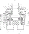
图1是本发明的主剖视图。Fig. 1 is a front sectional view of the present invention.
图2是本发明的图1中A-A截面图。Fig. 2 is a sectional view of A-A in Fig. 1 of the present invention.
图中:壳体1、电机2、电机腔体3、螺纹孔4、盖板5、主动齿轮6、输出轴7、平面凸轮8、凸轮槽9、总出油口10、油道轴11、第一密封圈12、弹性挡圈13、定位环14、定位隔板15、第二密封圈16、第三密封圈17、一号进油道18、二号进油道19、第二顶杆切换装置20、第二过油通道21、第二过油孔22、第二油道板23、第一油道板24、第一过油孔25、第一过油通道26、复位弹簧27、配合密封圈28、阀芯29、顶杆30、第四密封圈31、滚珠安装孔32、滚珠33。In the figure: housing 1,
具体实施方式Detailed ways
下面结合附图对本发明的实施方式做进一步的说明。Embodiments of the present invention will be further described below in conjunction with the accompanying drawings.
实施例1:Example 1:
如图1-2所示,汽车油箱转换阀,它包括壳体1,所述壳体1内部安装有驱动平面凸轮8的齿轮传动机构,所述平面凸轮8套装在油道轴11的外部,所述油道轴11安装在壳体1内部,所述平面凸轮8的端面加工有凸轮槽9,所述壳体1上安装有盖板5,所述油道轴11穿过盖板5,所述盖板5外部的油道轴11上设置有总出油口10;所述壳体1上设置有一号进油道18和二号进油道19,所述平面凸轮8与用于在两个进油道进行进油连通切换的顶杆切换装置相连。工作过程中,通过上述的结构能够在平面凸轮8的作用下,带动两个顶杆切换装置,进而通过两个顶杆切换装置的作用在两个进油道之间进行自动的切换。As shown in Figure 1-2, the automotive fuel tank switching valve includes a housing 1, a gear transmission mechanism for driving a plane cam 8 is installed inside the housing 1, and the plane cam 8 is sleeved on the outside of the
进一步的,所述齿轮传动机构包括电机2,所述电机2安装在壳体1内部的电机腔体3内部,所述电机2的输出轴7上安装有主动齿轮6,所述主动齿轮6与平面凸轮8外缘的从动齿轮构成齿轮啮合传动。工作过程中通过,电机2带动输出轴7,通过输出轴7带动主动齿轮6,通过主动齿轮6带动平面凸轮8,进而通过平面凸轮8带动顶杆切换装置,实现两个油道之间的自动切换。Further, the gear transmission mechanism includes a
进一步的,所述电机2采用减速伺服电机,所述减速伺服电机通过变频器与控制器相连,所述控制器通过信号线与伺服控制按钮相连控制电机2的自动转动以及其转动的相位角。工作过程中,通过控制器和变频器的作用控制减速伺服电机,进而通过减速伺服电机带动主动齿轮6转动一定的圈数,进而使平面凸轮8转动一定的相位角,并与两个顶杆切换装置配合工作。Further, the
进一步的,所述顶杆切换装置共有两套,包括第一顶杆切换装置和第二顶杆切换装置20;两套所述顶杆切换装置的结构相同;所述第一顶杆切换装置包括顶杆30,所述顶杆30的两端分别支撑在油道轴11和壳体1上的定位支撑孔,并构成滑动配合,在顶杆30上与平面凸轮8相配合的一端加工有滚珠安装孔32,所述滚珠安装孔32内部镶嵌安装有滚珠33,所述滚珠33与凸轮槽9构成滚动配合,所述顶杆30上通过轴肩定位安装有阀芯29,所述阀芯29和第一油道板24之间的顶杆30上套装有复位弹簧27,所述阀芯29上安装有配合密封圈28,所述配合密封圈28与第一过油通道26的末端倒角相配合并对第一过油通道26进行密封,进而对二号进油道19密封封堵,所述第一油道板24上均布加工有多个第一过油孔25。工作过程中,通过平面凸轮8与第一顶杆切换装置和第二顶杆切换装置20的顶杆30相配合,能够通过阀芯与第一过油通道26和第二过油通道21之间的配合,最终实现在两个油箱之间的自动切换。Further, there are two sets of the ejector pin switching devices, including a first ejector pin switching device and a second ejector
进一步的,所述第二顶杆切换装置20的结构和第一顶杆切换装置的结构相同,所述第二顶杆切换装置20与第二过油通道21、第二油道板23和第二过油孔22相配合对一号进油道18的通断进行切换。Further, the structure of the second jack
进一步的,所述盖板5和油道轴11之间设置有第一密封圈12;所述盖板5和壳体1相配合的端面之间设置有第二密封圈16;所述油道轴11和壳体1相配合的端面之间设置有第三密封圈17。工作过程中,通过上述的多个密封圈能够保证上述各个部件之间的密封。Further, a
进一步的,所述第一顶杆切换装置和第二顶杆切换装置20的顶杆与油道轴11相配合的位置设置有第四密封圈31。Further, a fourth sealing ring 31 is provided at the position where the ejector rods of the first ejector rod switching device and the second ejector
进一步的,所述平面凸轮8端面的凸轮槽9相位差为180度,保证平面凸轮8转动180度时,一号进油道18和二号进油道19分别处于关闭和开启状态。Further, the phase difference of the cam grooves 9 on the end surface of the plane cam 8 is 180 degrees, which ensures that when the plane cam 8 rotates 180 degrees, the No. 1
进一步的,所述平面凸轮8的下端面通过定位隔板15定位安装在油道轴11上,所述平面凸轮8的上端面通过定位环14定位,所述定位环14通过弹性挡圈13定位安装在油道轴11上,所述弹性挡圈13安装在油道轴11的轴环上。Further, the lower end surface of the plane cam 8 is positioned and installed on the
实施例2:Example 2:
采用任意一项所述汽车油箱转换阀的操作方法,它包括以下步骤:Adopt the operation method of any one described automobile fuel tank switching valve, it comprises the following steps:
第一步,分别将转换阀的一号进油道18和二号进油道19通过油管与第一油箱和第二油箱相连通,并将总出油口10与供油管道相连通;In the first step, respectively connect No. 1
第二步,初始时第二顶杆切换装置20的顶杆位于凸轮槽9的远休端,此时第二顶杆切换装置20的阀芯在复位弹簧作用下被顶起,使第二过油通道21开启,进而使一号进油道18和总出油口10相连通,并给供油管道供油;In the second step, initially, the ejector rod of the second ejector
第三步,当第一油箱的燃油用尽之后,按动伺服控制按钮,使电机2转动,进而带动平面凸轮8转动,进而使平面凸轮8的相位角转动180度,此时凸轮槽9的相位角也转换180度,使第二顶杆切换装置20将第二过油通道21关闭,第一顶杆切换装置将第一过油通道26开启,进而通过二号进油道19和总出油口10相连通,并给供油管道供油;In the third step, when the fuel in the first fuel tank is used up, press the servo control button to make the
第四步,当第二油箱的燃油用尽之后,按照同样的方法循环上述的操作过程,最终实现两个油箱的油循环供给。The fourth step, when the fuel in the second fuel tank is exhausted, repeat the above-mentioned operation process in the same way, and finally realize the oil circulation supply of the two fuel tanks.
通过上述的说明内容,本领域技术人员完全可以在不偏离本项发明技术思想的范围内,进行多样的变更以及修改都在本发明的保护范围之内。本发明的未尽事宜,属于本领域技术人员的公知常识。Through the above description, those skilled in the art can make various changes and modifications without departing from the technical idea of the present invention, all of which are within the protection scope of the present invention. Matters not covered in the present invention belong to the common knowledge of those skilled in the art.
Claims (7)
Priority Applications (2)
| Application Number | Priority Date | Filing Date | Title |
|---|---|---|---|
| CN202211481316.8A CN115750848A (en) | 2017-04-22 | 2017-04-22 | Method for operating a change-over valve of a motor vehicle tank |
| CN201710267825.3A CN107061791B (en) | 2017-04-22 | 2017-04-22 | Automobile oil tank switch valve and operation method |
Applications Claiming Priority (1)
| Application Number | Priority Date | Filing Date | Title |
|---|---|---|---|
| CN201710267825.3A CN107061791B (en) | 2017-04-22 | 2017-04-22 | Automobile oil tank switch valve and operation method |
Related Child Applications (1)
| Application Number | Title | Priority Date | Filing Date |
|---|---|---|---|
| CN202211481316.8A Division CN115750848A (en) | 2017-04-22 | 2017-04-22 | Method for operating a change-over valve of a motor vehicle tank |
Publications (2)
| Publication Number | Publication Date |
|---|---|
| CN107061791A CN107061791A (en) | 2017-08-18 |
| CN107061791B true CN107061791B (en) | 2023-01-31 |
Family
ID=59603311
Family Applications (2)
| Application Number | Title | Priority Date | Filing Date |
|---|---|---|---|
| CN201710267825.3A Active CN107061791B (en) | 2017-04-22 | 2017-04-22 | Automobile oil tank switch valve and operation method |
| CN202211481316.8A Pending CN115750848A (en) | 2017-04-22 | 2017-04-22 | Method for operating a change-over valve of a motor vehicle tank |
Family Applications After (1)
| Application Number | Title | Priority Date | Filing Date |
|---|---|---|---|
| CN202211481316.8A Pending CN115750848A (en) | 2017-04-22 | 2017-04-22 | Method for operating a change-over valve of a motor vehicle tank |
Country Status (1)
| Country | Link |
|---|---|
| CN (2) | CN107061791B (en) |
Families Citing this family (1)
| Publication number | Priority date | Publication date | Assignee | Title |
|---|---|---|---|---|
| CN110552826B (en) * | 2019-09-20 | 2023-09-01 | 宜昌市车的技术有限公司 | Automobile fuel tank changeover valve with automatic heating and manual function delayed oil return and its use method |
Family Cites Families (6)
| Publication number | Priority date | Publication date | Assignee | Title |
|---|---|---|---|---|
| WO1999051898A1 (en) * | 1998-04-02 | 1999-10-14 | R & K Developments Limited | Single lever mixing and flow rate control valve |
| FR2955168B1 (en) * | 2010-01-14 | 2012-02-10 | Mann & Hummel Gmbh | CONTROL VALVE FOR LIQUID CIRCULATION CIRCUIT |
| CN202001664U (en) * | 2011-01-18 | 2011-10-05 | 厦门市易洁卫浴有限公司 | Cam-switching valve |
| CN103615569A (en) * | 2013-09-24 | 2014-03-05 | 汤明江 | Segmented knob type constant-current water mixing valve |
| CN205781289U (en) * | 2016-07-11 | 2016-12-07 | 浙江荣鹏气动工具有限公司 | A kind of air tool valve mechanism |
| CN206669026U (en) * | 2017-04-22 | 2017-11-24 | 宜昌市车的技术有限公司 | Automotive oil tank switching valve |
-
2017
- 2017-04-22 CN CN201710267825.3A patent/CN107061791B/en active Active
- 2017-04-22 CN CN202211481316.8A patent/CN115750848A/en active Pending
Also Published As
| Publication number | Publication date |
|---|---|
| CN107061791A (en) | 2017-08-18 |
| CN115750848A (en) | 2023-03-07 |
Similar Documents
| Publication | Publication Date | Title |
|---|---|---|
| CN106917707B (en) | Automobile oil tank change-over valve with time-delay oil return function and operation method | |
| CN203641475U (en) | Rotary automatic transmission shift control valve | |
| CN110822131B (en) | Fuel switching valve of main and auxiliary fuel tanks for vehicle | |
| CN107061791B (en) | Automobile oil tank switch valve and operation method | |
| CN101324279B (en) | Rotary type fluid-distributing valve | |
| CN112066025B (en) | Hydraulic valve with lubricating function | |
| CN104976379B (en) | Rotary threeway scavenging air valve | |
| CN201613054U (en) | Positioning backwashing sewage filter | |
| CN107061796B (en) | Rotary gear shifting type multi-oil-way hydraulic control switch | |
| CN205618481U (en) | Inhale oil filter with check valve | |
| CN206669026U (en) | Automotive oil tank switching valve | |
| CN207421739U (en) | A kind of grease pumping installations | |
| CN107366742B (en) | Pneumatic gear shifting control device and gear shifting control method for mechanical automatic transmission | |
| CN205260913U (en) | Guide's valve that commutates | |
| WO2019080698A1 (en) | Grease pump | |
| CN110925393B (en) | Speed reduction device and loading and unloading machine | |
| CN104728416A (en) | Dual clutch transmission with improved oil pump arrangement structure | |
| CN212360962U (en) | Canned type electric actuator with manual emergency switch | |
| CN219366447U (en) | Intelligent electric control hydraulic reversing valve | |
| CN202387361U (en) | Micro-heat regenerative adsorption type dryer controlled by multi-channel switching valve | |
| CN210638956U (en) | Sewage sampling device for sewage treatment | |
| CN203584936U (en) | Hand guided rice transplanter pump valve | |
| CN103277539B (en) | Multifunctional pneumatic valve | |
| CN206647191U (en) | A kind of automotive oil tank switching valve of band delay oil return function | |
| CN104214158B (en) | Solenoid control valve assembly for hydraulic transmission gear box |
Legal Events
| Date | Code | Title | Description |
|---|---|---|---|
| PB01 | Publication | ||
| PB01 | Publication | ||
| SE01 | Entry into force of request for substantive examination | ||
| SE01 | Entry into force of request for substantive examination | ||
| GR01 | Patent grant | ||
| GR01 | Patent grant | ||
| PE01 | Entry into force of the registration of the contract for pledge of patent right |
Denomination of invention: Automobile fuel tank conversion valve and operation method Granted publication date: 20230131 Pledgee: Agricultural Bank of China Three Gorges Dongshan Branch Pledgor: YICHANG AUTOMOBILE TECHNOLOGY Co.,Ltd. Registration number: Y2025980003547 |