Motion control method and control device of quadruped robot based on sine diagonal gait and rapid table look-up method
Technical Field
The invention relates to a robot motion control method, in particular to a quadruped robot motion control method and a control device based on sine diagonal gait and a rapid table look-up method.
Background
With the rapid development of science and technology, the robot technology is developed rapidly. The robot can finish high-precision work quickly and accurately under the condition of being far away from human beings. Can be widely applied to the environments which are not suitable for human survival, such as rescue and relief work, planet detection, military mine clearance and the like. Compared with a wheeled or tracked robot, the foot type robot has certain advantages in movement in a non-structural environment. Among the multi-legged walking robots, the four-legged robot has a simple structure and stable movement, and has the most extensive research and application in the legged robot. However, the motion process of the quadruped robot is a multi-link, strong-coupling and time-varying nonlinear system, so that the motion control of the quadruped robot is very complicated. The existing method is mostly a quadruped robot gait control method based on torque control, and only can carry out motion control of fixed step length and fixed turning radius on the robot. The step length and the turning radius cannot be changed at will according to requirements.
Chinese patent document CN104267720A discloses a free gait generation method of a quadruped bionic robot, which is to plan the whole free gait of the quadruped robot according to the movement cycle, and each movement cycle is divided into a quadruped support phase and a stepping phase; in the four-foot supporting stage, four feet of the robot are all in a supporting phase, the gravity center of the robot moves along the advancing direction and the lateral direction of the advancing direction, the robot moves the maximum advancing distance allowed by the current state in the advancing direction, and the moving distance is determined by considering the stability and the energy consumption of the robot in the lateral direction; in the step stage, one foot of the robot is in a swing phase, and the other three feet are in a support phase; when the swing foot in a certain motion cycle contacts the ground, the robot performs the motion planning of the next motion cycle. However, this patent has the following drawbacks: the calculation cost is high, the foot end slides and is easy to cause disturbance, and the anti-interference capability is poor.
Disclosure of Invention
Aiming at the defects of the prior art, the invention provides a quadruped robot motion control method based on sine diagonal gait and a rapid table look-up method.
The invention also provides a four-footed robot motion control device based on the sine diagonal gait and the rapid table look-up method;
the invention obtains the leg movement mathematical model of the quadruped robot by analyzing the movement mechanism of the robot. On the basis, a novel sine diagonal gait is designed and adopted. Meanwhile, a special database for the motion control of the quadruped robot is designed, and the control rate of the quadruped robot can be obtained through a quick table look-up method. Finally, a foot end track control unit and a steering control unit are designed so as to be convenient for accessing other systems. In a word, the invention can better realize the motion control of the robot in the stepping period and has wide application value and research significance.
The technical scheme of the invention is as follows:
a quadruped robot motion control method based on sine diagonal gait and quick table look-up method, the quadruped robot comprises a trunk and four legs connected with the trunk, in a stepping period of the quadruped robot, two legs on the same diagonal swing in the same motion mode, two legs on the other diagonal supporting the trunk and pushing the trunk to advance are called as a supporting phase, and two legs on the other diagonal swinging according to a preset track are called as a swinging phase, the method comprises the following steps:
(1) through analysis four-footed robot shank structure, establish four-footed robot shank motion mathematical model, including four-footed robot foot end position model:
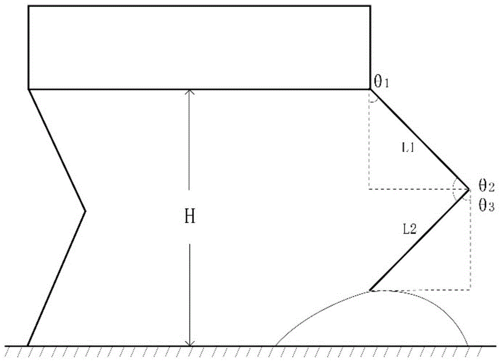
each leg comprises a thigh and a shank; a stepping cycle of the quadruped robot comprises a supporting phase and a swinging phase, in a trunk coordinate system, an x axis represents the displacement of a foot end in the horizontal direction, a y axis represents the height of the foot end, an origin o is a projection point of a hip joint of a leg on the ground, and a position model of the foot end in the trunk coordinate system is shown as formula (I):
in the formula (I), px(θ1,θ2) Is the horizontal displacement of the foot end and theta1、θ2Function of pz(θ1,θ2) Is the foot end height and theta1、θ2Function of L1Length of the thigh of the robot, L2Is the length of the lower leg of the robot, theta1The longitudinal opening and closing angle of the hip joint of the robot ranges from 0 degree to 180 degrees; theta2The opening and closing angle of the knee joint is 0-180 degrees; h is the distance from the bottom end of the robot trunk to the ground;
(2) adopting a novel sine opposite angle gait to obtain the motion trail of a supporting foot end under a trunk coordinate system and the motion trail of a swinging foot end under the trunk coordinate system, wherein the novel sine opposite angle gait is as follows: four legs of the four-legged robot are divided into two groups by opposite angles, a front left leg and a right back leg are one group, a front right leg and a back left leg are one group, and the two groups are alternately used as a supporting phase and a swinging phase; the supporting phase pushes the trunk to move forward, the swinging phase moves forward to stride across obstacles, and the processes can be explained through the foot end track. Especially the swing phase foot end trajectory, directly determines the way in which the swing phase takes a step. Therefore, the selection of the foot end track has great significance for the motion control of the robot.
The motion track of the supporting foot end under the coordinate system of the trunk is shown as the formula (II):
in formula (II), p1x(t) is a function of the horizontal displacement of the support foot end with respect to time t, p1z(T) supporting the function of the height of the foot end with respect to time T, wherein S is the step length of the current step cycle, S _1 is the actual step length of the previous step cycle, T is the time in the step cycle, and T is the step cycle;
the supporting phase supports the trunk and pushes the trunk to move forwards, so that in order to enable the robot to operate stably, the motion of the foot end of the supporting phase under the trunk coordinate system should be kept as uniform as possible, and the motion of the foot end of the supporting phase in the z-axis direction is kept unchanged. On the x0y plane, the support foot end performs uniform motion with a distance d equal to 0.5 (S + S _ 1).
The motion track of the swing phase foot end under the trunk coordinate system is shown as the formula (III):
in the formula (III), p2x(t) is a function of the horizontal displacement of the swing phase end with respect to time t, p2z(t) the height of the swing phase foot end as a function of time t, h being the step height and being the highest point reached during the swing phase rising process;
(3) solution of control rate
The range of the set step length is 0.38 m-0.42 m, the precision is 1mm, and the motion trail of the swing foot end under the trunk coordinate system has 41 × 41-1681 possibilities;
will have 1681 possibilitiesSubstituting the corresponding S _1 and S into the formula (III) to obtain the position p2 at different moments of the swing foot endx(t)、p2z(t);
The position p2 of the swing foot end at different time is obtainedx(t)、p2z(t) substitution into p in formula (I)x(θ1,θ2)、pz(θ1,θ2) Obtaining a nonlinear equation set, solving the nonlinear equation set through MATLAB, and screening according to joint constraint conditions to obtain a hip joint longitudinal opening and closing angle and a knee joint opening and closing angle which meet the joint constraint conditions, wherein the hip joint longitudinal opening and closing angle and the knee joint opening and closing angle are used as control rates for controlling the swing phase motion;
substituting S _1 and S corresponding to 1681 possibilities into formula (II) to obtain p1 at different time points of the supporting foot endx(t)、p1z(t);
The obtained positions p1 of the supporting foot ends at different momentsx(t)、p1z(t) substitution into p in formula (I)x(θ1,θ2)、pz(θ1,θ2) Obtaining a nonlinear equation set, solving the nonlinear equation set through MATLAB, and screening according to joint constraint conditions to obtain a hip joint longitudinal opening and closing angle and a knee joint opening and closing angle which meet the joint constraint conditions, wherein the hip joint longitudinal opening and closing angle and the knee joint opening and closing angle are used as control rates for controlling the movement of the support phases;
(4) establishing a database according to the calculated control rate of the motion of the swing phase and the control rate of the motion of the support phase
The database adopts a two-dimensional address pointer, the first dimension is S _1, the second dimension is S, each address stores 2 control matrixes of 2 x 200, and the control matrixes are respectively the support phase joint control rate and the swing phase joint control rate;
(5) the foot end track control of the quadruped robot is realized by a rapid table look-up method
A. Obtaining S and S _ 1;
B. performing quick table lookup according to the S _1 and the S, and obtaining a support phase control matrix storing the control rate of the support phase joint and a swing phase control matrix storing the control rate of the swing phase joint from a database;
C. transmitting the support phase control matrix to a support phase, transmitting the swing phase control matrix to a swing phase, and moving according to a corresponding control rate;
(6) steering control of a quadruped robot
And solving the control rate of the horizontal opening and closing angle of the hip joint of the support phase and the control rate of the horizontal opening and closing angle of the hip joint of the swing phase, and transmitting the control rates to the corresponding leg group to change the leg group according to the control rates so as to realize the steering control of the quadruped robot.
According to the present invention, the step (6) of controlling the steering of the quadruped robot includes the steps of:
a. acquiring the trunk orientation y _ theta _1 of the quadruped robot at the end moment of the previous stepping cycle and the trunk orientation theta at the end moment of the stepping cycle under an ideal condition;
b. the steering angle Δ θ of the trunk is obtained by the following formula (iv):
θ=y_θ_1+Δθ (Ⅳ)
c. during the movement of the robot, the steering of the trunk is realized by rotating the supporting phase in opposite directions by the same angle under a trunk coordinate system. Therefore, on the premise that the target steering angle is known, the control rate of the lateral opening/closing angle of the hip joint of the support phase is obtained, and the control rate θ of the lateral opening/closing angle of the hip joint of the support phase is obtained by the equation (V)4:
d. When the transverse opening and closing angle of the hip joint of the swing phase needs to be adjusted to be positive, in a preparation state, y _ theta _1 is equal to y _ theta _2, and the adjustment angle of the swing phase is obtained by carrying out iterative operation on the formula (VI) and is delta theta _1, wherein the value of the adjustment angle is the difference between the current trunk orientation y _ theta _1 and the trunk orientation y _ theta _2 at the initial moment of the previous period:
Δθ_1=y_θ_1-y_θ_2 (Ⅵ)
e. the control rate theta 1 of the transverse opening and closing angle of the swing phase hip joint is obtained through the formula (VII)4:
f. And transmitting the signals to corresponding leg groups through control rate distribution, and enabling the leg groups to change according to the control rate to realize steering control of the quadruped robot.
Compared with foot end track control, the steering control is simpler, the control rate can be directly obtained through an equation, and the steering control and the swing phase aligning control can be accurately realized only by distributing the control rate to the corresponding leg group.
According to a preferred embodiment of the present invention, the quadruped robot motion control method further includes:
when the robot moves on a complex ground, the swinging foot end and the ground can randomly slide relatively at the end of a step. This may affect the stability of the robot movement. In T/10 after the stepping period is finished, the foot end track control unit and the steering control unit work cooperatively to adjust the posture of the robot, and the randomly generated disturbance is assumed to be (delta p)x,Δpy),(Δpx,Δpy) Refers to the deviation from the target landing point, including:
the leg as the swing phase moves forwards along the ground, the energy consumption is reduced to the minimum while the posture is adjusted, the step length is delta r, and the energy consumption is obtained through the formula (VIII):
meanwhile, the support pushes the robot body forwards
While the transverse opening-closing angle of the hip joint is changed by delta theta
2The formula (IX) is used for solving:
through the adjustment, the orientation and the gravity center position of the robot trunk can be changed. But the hip joint connecting line of the left leg and the right leg can be kept in the middle of the drop point of the supporting foot end and the drop point of the swinging foot end, and the postures of the legs in the same leg group are the same. This provides a very high stability of the movement.
According to a preferred embodiment of the invention, the derivation of formula (i) is as follows:
the motion of the robot in a stepping cycle is determined by the orientation theta of the trunk of the robot, the step length S of the cycle and the actual step length S _1 of the previous cycle, and the mathematical model of the motion in the horizontal direction is shown as the formula (X):
the orientation and the step length of the trunk of the robot can be controlled by controlling each joint of four limbs, so that the leg structure and the motion mode of the quadruped robot need to be further analyzed.
Assuming that the foot end of the robot does not slide relative to the ground and the robot body does not deform, the motion of the robot body can be explained by the change of the foot end position and the body angle together, and the foot end position and the L of the robot are obtained by the formula (XI)1、L2、θ1、θ2Angle theta formed by the lower leg and the plumb line3The relationship of (1):
by analysing geometric relationships, theta3By theta1、θ2Expressed as shown in formula (XII):
θ3=π-θ1-θ2(Ⅻ)
the formula (XII) is introduced into the formula (XI) to obtain a mathematical model of the foot end position, namely (I).
According to a preferred embodiment of the invention, the derivation of the formula (iii) is as follows:
the supporting phase pushes the trunk to move forward, the swinging phase moves forward to stride across obstacles, and the processes can be explained through the foot end track. Especially the swing phase foot end trajectory, directly determines the way in which the swing phase takes a step. Therefore, the selection of the foot end track has great significance for the motion control of the robot.
The swing phase swings according to the planned foot end trajectory. In order to ensure that the swing phase motion process is smooth and energy-saving, the gait switching process is coherent and stable, and the walking mechanism has better trafficability, the motion trail of the swing phase foot end under the trunk coordinate system needs to meet the following specific constraint conditions:
① torso coordinate system, in the x-direction, at the beginning of the cycle, i.e. when t is 0, pxHalf the step length of the previous period, and the direction is negative; at the end of the cycle, i.e. when T equals T, pyHalf the cycle step, positive in direction, translates to a mathematical constraint, as shown in equation (XIII):
② in order to make the robot have better trafficability when facing complex terrain, the foot end of the swing phase rises and then falls in the swing process, the foot end should contact the ground at the beginning and the end, the height is 0, the height of the highest point reached in the rising process is h, which is called step height, and the mathematical constraint condition is converted as shown in formula (XIV):
③ because the swing phase will contact with the ground again when the swing is finished, if the force generated by the interaction between the foot end and the ground in the horizontal direction can be eliminated, the continuity and stability of the movement can be greatly improved, the invention proposes that the first derivative of the horizontal direction position is 0 at the moment of finishing the swing phase, i.e. the force generated by the interaction between the foot end and the ground in the horizontal direction is eliminated, at the same time, in order to meet the requirement of continuity and stability in the gait switching process, the second derivative of the horizontal direction position at the moment of finishing the swing phase needs to be less than 0, and the requirement is converted into the mathematical constraint condition shown in formula (XV):
and (3) combining the constraint conditions described in the formulas (XIII), (XIV) and (XV) to derive a swing phase end trajectory satisfying the requirements, as shown in the formula (III).
A quadruped robot motion control device based on sine diagonal gait and rapid table look-up method comprises a foot end track control unit and a steering control unit;
the foot end trajectory control unit is used for completing the following operations:
the foot end track control unit receives the motion distance U _ r _1 of the last cycle of the robot and the guide motion distance dr of the cycle, when the motion starts, the four-footed robot adjusts the posture to the preparation posture, the corresponding S _1 is 0.4m at the moment, and iterative operation is carried out on the formula (XVI) to obtain S and S _ 1:
in the formula (XVI), S _2 is the step length of the penultimate period;
performing quick table lookup according to the obtained S _1 and S, and obtaining a support phase control matrix with the support phase joint control rate and a swing phase control matrix with the swing phase joint control rate from a database;
transmitting the support phase control matrix to a support phase, transmitting the swing phase control matrix to a swing phase, and moving according to a corresponding control rate;
the steering control unit is used for calculating the control rate of the transverse opening and closing angle of the hip joint of the support phase and the control rate of the transverse opening and closing angle of the hip joint of the swing phase, transmitting the control rates to the corresponding leg groups, and enabling the leg groups to change according to the control rates to realize steering control of the quadruped robot.
The invention has the beneficial effects that:
1. in the aspect of trafficability, the robot has high trafficability when facing complex terrain due to the design and the adoption of a novel sinusoidal gait.
2. In terms of running stability, when the stepping period is cut off, the horizontal speed of the swing phase is zero, so that the stability is high.
3. The invention adopts a table look-up method to carry out rapid and accurate foot end track control, high speed, accuracy and stability and lower calculation cost.
4. After the normal gait cycle is finished, the invention can adjust the posture of the robot through the cooperative work of the foot end track control unit and the steering control unit so as to deal with the disturbance caused by the foot end sliding, thereby greatly enhancing the anti-interference capability of the gait control system of the quadruped robot.
Drawings
FIG. 1 is a schematic diagram of the torso and leg structure of a quadruped robot;
FIG. 2 is a schematic diagram of the swing phase end trajectory in an ideal case;
FIG. 3 is a foot end trajectory that may occur for the swing phase;
FIG. 4 is a control schematic of the foot end trajectory control unit;
FIG. 5 is a control effect diagram of the foot end trajectory control unit;
fig. 6 is a control schematic diagram of the steering control unit.
Detailed Description
The invention is further defined in the following, but not limited to, the figures and examples in the description.
Example 1
A quadruped robot motion control method based on sine diagonal gait and quick table look-up method, the quadruped robot comprises a trunk and four legs connected with the trunk, in a stepping period of the quadruped robot, two legs on the same diagonal swing in the same motion mode, two legs on the other diagonal supporting the trunk and pushing the trunk to advance are called as a supporting phase, and two legs on the other diagonal swinging according to a preset track are called as a swinging phase, the method comprises the following steps:
(1) through analysis four-footed robot shank structure, establish four-footed robot shank motion mathematical model, including four-footed robot foot end position model:
each leg comprises a thigh and a shank; a stepping cycle of the quadruped robot comprises a supporting phase and a swinging phase, in a trunk coordinate system, an x axis represents the displacement of a foot end in the horizontal direction, a y axis represents the height of the foot end, an origin o is a projection point of a hip joint of a leg on the ground, and a position model of the foot end in the trunk coordinate system is shown as formula (I):
in the formula (I), px(θ1,θ2) Is the horizontal displacement of the foot end and theta1、θ2Function of pz(θ1,θ2) Is the foot end height and theta1、θ2Function of L1Length of the thigh of the robot, L2Is the length of the lower leg of the robot, theta1The longitudinal opening and closing angle of the hip joint of the robot ranges from 0 degree to 180 degrees; theta2The opening and closing angle of the knee joint is 0-180 degrees; h is the distance from the bottom end of the robot trunk to the ground; FIG. 1 is a schematic diagram of the structure of the trunk and legs of a quadruped robot, which is mainly composed of a trunk and four legs that can swing flexibly, L1=L2300 mm; h is determined by the hip joint longitudinal opening and closing angle and the knee joint opening and closing angle in a static state, and H is 519.6 mm.
(2) Adopting a novel sine opposite angle gait to obtain the motion trail of a supporting foot end under a trunk coordinate system and the motion trail of a swinging foot end under the trunk coordinate system, wherein the novel sine opposite angle gait is as follows: four legs of the four-legged robot are divided into two groups by opposite angles, a front left leg and a right back leg are one group, a front right leg and a back left leg are one group, the same group moves in the same mode, and the two groups are alternately used as a supporting phase and a swinging phase; the supporting phase pushes the trunk to move forward, the swinging phase moves forward to stride across obstacles, and the processes can be explained through the foot end track. Especially the swing phase foot end trajectory, directly determines the way in which the swing phase takes a step. Therefore, the selection of the foot end track has great significance for the motion control of the robot.
The motion track of the supporting foot end under the coordinate system of the trunk is shown as the formula (II):
in formula (II), p1x(t) is a function of the horizontal displacement of the support foot end with respect to time t, p1z(T) supporting the function of the height of the foot end with respect to time T, wherein S is the step length of the current step cycle, S _1 is the actual step length of the previous step cycle, T is the time in the step cycle, and T is the step cycle;
the supporting phase supports the trunk and pushes the trunk to move forwards, so that in order to enable the robot to operate stably, the motion of the foot end of the supporting phase under the trunk coordinate system should be kept as uniform as possible, and the motion of the foot end of the supporting phase in the z-axis direction is kept unchanged. On the x0y plane, the support foot end performs uniform motion with a distance d equal to 0.5 (S + S _ 1).
The motion track of the swing phase foot end under the trunk coordinate system is shown as the formula (III):
in the formula (III), p2x(t) is a function of the horizontal displacement of the swing phase end with respect to time t, p2z(t) the height of the swing phase foot end as a function of time t, h being the step height and being the highest point reached during the swing phase rising process; s — 1 — 0.4m, with the foot end trajectory shown in fig. 2;
(3) solution of control rate
The range of the set step length is 0.38 m-0.42 m, the precision is 1mm, and the motion trail of the swing foot end under the trunk coordinate system has 41 × 41-1681 possibilities; as shown in fig. 3.
Substituting S _1 and S corresponding to 1681 possibilities into formula (III) to obtain positions p2 at different moments of the swing phase endx(t)、p2z(t);
The position p2 of the swing foot end at different time is obtainedx(t)、p2z(t) substitution into p in formula (I)x(θ1,θ2)、pz(θ1,θ2) Obtaining a nonlinear equation set, and solving the nonlinear equation set through MATLABScreening according to the joint constraint conditions to obtain longitudinal hip joint opening and closing angles and knee joint opening and closing angles which accord with the joint constraint conditions, wherein the longitudinal hip joint opening and closing angles and the knee joint opening and closing angles are used as control rates for controlling the swinging phase motion;
substituting S _1 and S corresponding to 1681 possibilities into formula (II) to obtain p1 at different time points of the supporting foot endx(t)、p1z(t);
The obtained positions p1 of the supporting foot ends at different momentsx(t)、p1z(t) substitution into p in formula (I)x(θ1,θ2)、pz(θ1,θ2) Obtaining a nonlinear equation set, solving the nonlinear equation set through MATLAB, and screening according to joint constraint conditions to obtain a hip joint longitudinal opening and closing angle and a knee joint opening and closing angle which meet the joint constraint conditions, wherein the hip joint longitudinal opening and closing angle and the knee joint opening and closing angle are used as control rates for controlling the movement of the support phases;
(4) establishing a database according to the calculated control rate of the motion of the swing phase and the control rate of the motion of the support phase
The database adopts a two-dimensional address pointer, the first dimension is S _1, the second dimension is S, each address stores 2 control matrixes of 2 x 200, and the control matrixes are respectively the support phase joint control rate and the swing phase joint control rate;
(5) the foot end track control of the quadruped robot is realized by a rapid table look-up method
A. Obtaining S and S _ 1;
B. performing quick table lookup according to the S _1 and the S, and obtaining a support phase control matrix storing the control rate of the support phase joint and a swing phase control matrix storing the control rate of the swing phase joint from a database;
C. transmitting the support phase control matrix to a support phase, transmitting the swing phase control matrix to a swing phase, and moving according to a corresponding control rate;
(6) steering control of a quadruped robot
And solving the control rate of the horizontal opening and closing angle of the hip joint of the support phase and the control rate of the horizontal opening and closing angle of the hip joint of the swing phase, and transmitting the control rates to the corresponding leg group to change the leg group according to the control rates so as to realize the steering control of the quadruped robot.
And (6) steering control is carried out on the quadruped robot, and the steering control method comprises the following steps:
a. acquiring the trunk orientation y _ theta _1 of the quadruped robot at the end moment of the previous stepping cycle and the trunk orientation theta at the end moment of the stepping cycle under an ideal condition;
b. the steering angle Δ θ of the trunk is obtained by the following formula (iv):
θ=y_θ_1+Δθ (Ⅳ)
c. during the movement of the robot, the steering of the trunk is realized by rotating the supporting phase in opposite directions by the same angle under a trunk coordinate system. Therefore, on the premise that the target steering angle is known, the control rate of the lateral opening/closing angle of the hip joint of the support phase is obtained, and the control rate θ of the lateral opening/closing angle of the hip joint of the support phase is obtained by the equation (V)4:
d. When the transverse opening and closing angle of the hip joint of the swing phase needs to be adjusted to be positive, in a preparation state, y _ theta _1 is equal to y _ theta _2, and the adjustment angle of the swing phase is obtained by carrying out iterative operation on the formula (VI) and is delta theta _1, wherein the value of the adjustment angle is the difference between the current trunk orientation y _ theta _1 and the trunk orientation y _ theta _2 at the initial moment of the previous period:
Δθ_1=y_θ_1-y_θ_2 (Ⅵ)
e. the control rate theta 1 of the transverse opening and closing angle of the swing phase hip joint is obtained through the formula (VII)4:
f. And transmitting the signals to corresponding leg groups through control rate distribution, and enabling the leg groups to change according to the control rate to realize steering control of the quadruped robot.
Compared with foot end track control, the steering control is simpler, the control rate can be directly obtained through an equation, and the steering control and the swing phase aligning control can be accurately realized only by distributing the control rate to the corresponding leg group.
The quadruped robot motion control method further comprises the following steps:
when the robot moves on a complex ground, the swinging foot end and the ground can randomly slide relatively at the end of a step. This may affect the stability of the robot movement. In T/10 after the stepping period is finished, the foot end track control unit and the steering control unit work cooperatively to adjust the posture of the robot, and the randomly generated disturbance is assumed to be (delta p)x,Δpy),(Δpx,Δpy) Refers to the deviation from the target landing point, including:
the leg as the swing phase moves forwards along the ground, the energy consumption is reduced to the minimum while the posture is adjusted, the step length is delta r, and the energy consumption is obtained through the formula (VIII):
meanwhile, the support pushes the robot body forwards
While the transverse opening-closing angle of the hip joint is changed by delta theta
2The formula (IX) is used for solving:
through the adjustment, the orientation and the gravity center position of the robot trunk can be changed. But the hip joint connecting line of the left leg and the right leg can be kept in the middle of the drop point of the supporting foot end and the drop point of the swinging foot end, and the postures of the legs in the same leg group are the same. This provides a very high stability of the movement.
The derivation of formula (I) is as follows:
the motion of the robot in a stepping cycle is determined by the orientation theta of the trunk of the robot, the step length S of the cycle and the actual step length S _1 of the previous cycle, and the mathematical model of the motion in the horizontal direction is shown as the formula (X):
the orientation and the step length of the trunk of the robot can be controlled by controlling each joint of four limbs, so that the leg structure and the motion mode of the quadruped robot need to be further analyzed.
Assuming that the foot end of the robot does not slide relative to the ground and the robot body does not deform, the motion of the robot body can be explained by the change of the foot end position and the body angle together, and the foot end position and the L of the robot are obtained by the formula (XI)1、L2、θ1、θ2Angle theta formed by the lower leg and the plumb line3The relationship of (1):
by analysing geometric relationships, theta3By theta1、θ2Expressed as shown in formula (XII):
θ3=π-θ1-θ2(Ⅻ)
the formula (XII) is introduced into the formula (XI) to obtain a mathematical model of the foot end position, namely (I).
The derivation of formula (III) is as follows:
the supporting phase pushes the trunk to move forward, the swinging phase moves forward to stride across obstacles, and the processes can be explained through the foot end track. Especially the swing phase foot end trajectory, directly determines the way in which the swing phase takes a step. Therefore, the selection of the foot end track has great significance for the motion control of the robot.
The swing phase swings according to the planned foot end trajectory. In order to ensure that the swing phase motion process is smooth and energy-saving, the gait switching process is coherent and stable, and the walking stick has better trafficability, the motion trail of the swing phase foot end under the trunk coordinate system needs to meet the following specific constraint conditions,
the specific constraints are as follows:
① torso coordinate system, in the x-direction, at the beginning of the cycle, i.e. when t is 0, pxIs one of the last cycle stepHalf, the direction is negative; at the end of the cycle, i.e. when T equals T, pyHalf the cycle step, positive in direction, translates to a mathematical constraint, as shown in equation (XIII):
② in order to make the robot have better trafficability when facing complex terrain, the foot end of the swing phase rises and then falls in the swing process, the foot end should contact the ground at the beginning and the end, the height is 0, the height of the highest point reached in the rising process is h, which is called step height, and the mathematical constraint condition is converted as shown in formula (XIV):
③ because the swing phase will contact with the ground again when the swing is finished, if the force generated by the interaction between the foot end and the ground in the horizontal direction can be eliminated, the continuity and stability of the movement can be greatly improved, the invention proposes that the first derivative of the horizontal direction position is 0 at the moment of finishing the swing phase, i.e. the force generated by the interaction between the foot end and the ground in the horizontal direction is eliminated, at the same time, in order to meet the requirement of continuity and stability in the gait switching process, the second derivative of the horizontal direction position at the moment of finishing the swing phase needs to be less than 0, and the requirement is converted into the mathematical constraint condition shown in formula (XV):
and (3) combining the constraint conditions described in the formulas (XIII), (XIV) and (XV) to derive a swing phase end trajectory satisfying the requirements, as shown in the formula (III).
In the traditional method, forward and inverse kinematics derivation is adopted, and the relationship between the opening and closing angle and the position of the foot end of each joint can be obtained only by complex formula derivation. The table look-up method obtains the joint angle corresponding to each foot end position through software calculation and establishes a database, and when the table look-up method is used, the operation complexity is low and the real-time performance is good.
Example 2
A quadruped robot motion control device based on sine diagonal gait and rapid table look-up method comprises a foot end track control unit and a steering control unit; FIG. 4 is a control schematic of the foot end trajectory control unit;
the foot end trajectory control unit is used for completing the following operations:
the foot end track control unit receives the motion distance U _ r _1 of the last cycle of the robot and the guide motion distance dr of the cycle, when the motion starts, the four-footed robot adjusts the posture to the preparation posture, the corresponding S _1 is 0.4m at the moment, and iterative operation is carried out on the formula (XVI) to obtain S and S _ 1:
in the formula (XVI), S _2 is the step length of the penultimate period;
performing quick table lookup according to the obtained S _1 and S, and obtaining a support phase control matrix with the support phase joint control rate and a swing phase control matrix with the swing phase joint control rate from a database;
transmitting the support phase control matrix to a support phase, transmitting the swing phase control matrix to a swing phase, and moving according to a corresponding control rate; FIG. 5 is a control effect diagram of the foot end trajectory control unit; as can be seen from fig. 5, the control effect is very ideal, and the foot end trajectory control unit can accurately realize the support phase control and the swing phase control.
The steering control unit is used for calculating the control rate of the transverse opening and closing angle of the hip joint of the support phase and the control rate of the transverse opening and closing angle of the hip joint of the swing phase, transmitting the control rates to the corresponding leg groups, and enabling the leg groups to change according to the control rates to realize steering control of the quadruped robot. Compared with foot end track control, the steering control is simpler, the control rate can be directly obtained through an equation, and the steering control and the swing phase aligning control can be accurately realized only by distributing the control rate to the corresponding leg group. Fig. 6 is a control schematic diagram of the steering control unit.