CN106980314B - Motion control method and electronic equipment - Google Patents
Motion control method and electronic equipment Download PDFInfo
- Publication number
- CN106980314B CN106980314B CN201710151346.5A CN201710151346A CN106980314B CN 106980314 B CN106980314 B CN 106980314B CN 201710151346 A CN201710151346 A CN 201710151346A CN 106980314 B CN106980314 B CN 106980314B
- Authority
- CN
- China
- Prior art keywords
- wheel
- distance
- electronic device
- rotate
- controlling
- Prior art date
- Legal status (The legal status is an assumption and is not a legal conclusion. Google has not performed a legal analysis and makes no representation as to the accuracy of the status listed.)
- Active
Links
- 238000000034 method Methods 0.000 title claims abstract description 28
- 238000012544 monitoring process Methods 0.000 claims abstract description 23
- 238000010586 diagram Methods 0.000 description 8
- 230000001133 acceleration Effects 0.000 description 7
- 230000003044 adaptive effect Effects 0.000 description 6
- 230000004888 barrier function Effects 0.000 description 6
- 230000008878 coupling Effects 0.000 description 3
- 238000010168 coupling process Methods 0.000 description 3
- 238000005859 coupling reaction Methods 0.000 description 3
- 238000004891 communication Methods 0.000 description 2
- 230000006870 function Effects 0.000 description 2
- 238000006467 substitution reaction Methods 0.000 description 2
- 206010063385 Intellectualisation Diseases 0.000 description 1
- 238000011161 development Methods 0.000 description 1
- 238000005516 engineering process Methods 0.000 description 1
- 238000012545 processing Methods 0.000 description 1
Images


Classifications
-
- G—PHYSICS
- G05—CONTROLLING; REGULATING
- G05D—SYSTEMS FOR CONTROLLING OR REGULATING NON-ELECTRIC VARIABLES
- G05D1/00—Control of position, course or altitude of land, water, air, or space vehicles, e.g. automatic pilot
- G05D1/0088—Control of position, course or altitude of land, water, air, or space vehicles, e.g. automatic pilot characterized by the autonomous decision making process, e.g. artificial intelligence, predefined behaviours
-
- G—PHYSICS
- G05—CONTROLLING; REGULATING
- G05D—SYSTEMS FOR CONTROLLING OR REGULATING NON-ELECTRIC VARIABLES
- G05D1/00—Control of position, course or altitude of land, water, air, or space vehicles, e.g. automatic pilot
- G05D1/0055—Control of position, course or altitude of land, water, air, or space vehicles, e.g. automatic pilot with safety arrangements
-
- G—PHYSICS
- G05—CONTROLLING; REGULATING
- G05D—SYSTEMS FOR CONTROLLING OR REGULATING NON-ELECTRIC VARIABLES
- G05D1/00—Control of position, course or altitude of land, water, air, or space vehicles, e.g. automatic pilot
- G05D1/02—Control of position or course in two dimensions
- G05D1/021—Control of position or course in two dimensions specially adapted to land vehicles
- G05D1/0212—Control of position or course in two dimensions specially adapted to land vehicles with means for defining a desired trajectory
- G05D1/0214—Control of position or course in two dimensions specially adapted to land vehicles with means for defining a desired trajectory in accordance with safety or protection criteria, e.g. avoiding hazardous areas
-
- G—PHYSICS
- G05—CONTROLLING; REGULATING
- G05D—SYSTEMS FOR CONTROLLING OR REGULATING NON-ELECTRIC VARIABLES
- G05D1/00—Control of position, course or altitude of land, water, air, or space vehicles, e.g. automatic pilot
- G05D1/02—Control of position or course in two dimensions
- G05D1/021—Control of position or course in two dimensions specially adapted to land vehicles
- G05D1/0212—Control of position or course in two dimensions specially adapted to land vehicles with means for defining a desired trajectory
- G05D1/0223—Control of position or course in two dimensions specially adapted to land vehicles with means for defining a desired trajectory involving speed control of the vehicle
-
- G—PHYSICS
- G05—CONTROLLING; REGULATING
- G05D—SYSTEMS FOR CONTROLLING OR REGULATING NON-ELECTRIC VARIABLES
- G05D1/00—Control of position, course or altitude of land, water, air, or space vehicles, e.g. automatic pilot
- G05D1/02—Control of position or course in two dimensions
- G05D1/021—Control of position or course in two dimensions specially adapted to land vehicles
- G05D1/0231—Control of position or course in two dimensions specially adapted to land vehicles using optical position detecting means
- G05D1/0238—Control of position or course in two dimensions specially adapted to land vehicles using optical position detecting means using obstacle or wall sensors
- G05D1/024—Control of position or course in two dimensions specially adapted to land vehicles using optical position detecting means using obstacle or wall sensors in combination with a laser
-
- G—PHYSICS
- G05—CONTROLLING; REGULATING
- G05D—SYSTEMS FOR CONTROLLING OR REGULATING NON-ELECTRIC VARIABLES
- G05D1/00—Control of position, course or altitude of land, water, air, or space vehicles, e.g. automatic pilot
- G05D1/02—Control of position or course in two dimensions
- G05D1/021—Control of position or course in two dimensions specially adapted to land vehicles
- G05D1/0255—Control of position or course in two dimensions specially adapted to land vehicles using acoustic signals, e.g. ultra-sonic singals
Abstract
The invention discloses a motion control method and electronic equipment, wherein the method comprises the following steps: monitoring a first distance from a first wheel to an obstacle along a first direction, and monitoring a second distance from a second wheel to the obstacle along the first direction, wherein the first wheel and the second wheel are arranged on two sides of an electronic device; comparing the magnitude of the first distance and the second distance; if the first distance is greater than the second distance, controlling a rotation parameter of the first wheel and/or the second wheel to enable the electronic device to rotate to the left; controlling a rotation parameter of the first wheel and/or the second wheel to cause the electronic device to rotate to the right if the first distance is less than the second distance.
Description
Technical Field
The present invention relates to an auto-cruise technology, and more particularly, to a motion control method and an electronic device for auto-cruise.
Background
With the development of robot intellectualization, more and more robots have an automatic cruise function. The automatic cruise is that: and planning the cruise path according to a preset strategy, and then controlling the robot to move according to the planned cruise path. However, the cruise condition is that the route is an open route, and complicated road conditions are not considered, for example, some complicated corners or some places have obstacles, and the robot cannot avoid the obstacles, which may cause a cruise failure or even damage the robot.
Disclosure of Invention
In order to solve the above technical problems, embodiments of the present invention provide a motion control method and an electronic device.
The motion control method provided by the embodiment of the invention comprises the following steps:
monitoring a first distance from a first wheel to an obstacle along a first direction, and monitoring a second distance from a second wheel to the obstacle along the first direction, wherein the first wheel and the second wheel are arranged on two sides of an electronic device;
comparing the magnitude of the first distance and the second distance;
if the first distance is greater than the second distance, controlling a rotation parameter of the first wheel and/or the second wheel to enable the electronic device to rotate to the left;
controlling a rotation parameter of the first wheel and/or the second wheel to cause the electronic device to rotate to the right if the first distance is less than the second distance.
In this embodiment of the present invention, before comparing the magnitudes of the first distance and the second distance, the method further includes:
acquiring the minimum value of the first distance and the second distance, and judging whether the minimum value is greater than or equal to a preset length;
and if the minimum value is larger than or equal to the preset length, comparing the first distance with the second distance.
In the embodiment of the present invention, the method further includes:
and if the minimum value is smaller than the preset length, controlling the first wheel and/or the second wheel to rotate along a second direction until the minimum value is larger than or equal to the preset length and stopping rotating.
In an embodiment of the present invention, the controlling the rotation parameter of the first wheel and/or the second wheel to rotate the electronic device to the left includes:
controlling the first wheel to stop rotating and controlling the second wheel to rotate along a third direction, so that the electronic equipment rotates to the left; alternatively, the first and second electrodes may be,
the first wheel is controlled to rotate along a second direction, and the second wheel is controlled to rotate along a third direction, so that the electronic equipment rotates leftwards.
In an embodiment of the present invention, the controlling the rotation parameter of the first wheel and/or the second wheel to rotate the electronic device to the right includes:
controlling the second wheel to stop rotating, and controlling the first wheel to rotate along a third direction, so that the electronic equipment rotates to the right; alternatively, the first and second electrodes may be,
and controlling the second wheel to rotate along a second direction, and controlling the first wheel to rotate along a third direction, so that the electronic equipment rotates to the right.
The electronic device provided by the embodiment of the invention comprises: the first wheel and the second wheel are arranged on two sides of the electronic equipment;
a sensor for monitoring a first distance of a first wheel from an obstacle along a first direction and monitoring a second distance of a second wheel from the obstacle along the first direction;
a processor for comparing the magnitudes of the first and second distances; if the first distance is greater than the second distance, controlling a rotation parameter of the first wheel and/or the second wheel to enable the electronic device to rotate to the left; controlling a rotation parameter of the first wheel and/or the second wheel to cause the electronic device to rotate to the right if the first distance is less than the second distance.
In the embodiment of the present invention, the processor is further configured to obtain a minimum value of the first distance and the second distance, and determine whether the minimum value is greater than or equal to a preset length; and if the minimum value is larger than or equal to the preset length, comparing the first distance with the second distance.
In an embodiment of the present invention, the processor is further configured to control the first wheel and/or the second wheel to rotate in the second direction if the minimum value is smaller than the preset length, until the minimum value is greater than or equal to the preset length, and stop rotating.
In an embodiment of the present invention, the processor is further configured to control the first wheel to stop rotating, and control the second wheel to rotate in a third direction, so that the electronic device rotates to the left; or the first wheel is controlled to rotate along a second direction, and the second wheel is controlled to rotate along a third direction, so that the electronic equipment rotates leftwards.
In an embodiment of the present invention, the processor is further configured to control the second wheel to stop rotating, and control the first wheel to rotate along a third direction, so that the electronic device rotates to the right; or the second wheel is controlled to rotate along a second direction, and the first wheel is controlled to rotate along a third direction, so that the electronic equipment rotates to the right.
In the technical scheme of the embodiment of the invention, a first distance from a first wheel to an obstacle body along a first direction is monitored, and a second distance from a second wheel to the obstacle body along the first direction is monitored, wherein the first wheel and the second wheel are arranged on two sides of an electronic device; comparing the magnitude of the first distance and the second distance; if the first distance is greater than the second distance, controlling a rotation parameter of the first wheel and/or the second wheel to enable the electronic device to rotate to the left; controlling a rotation parameter of the first wheel and/or the second wheel to cause the electronic device to rotate to the right if the first distance is less than the second distance. By adopting the technical scheme of the embodiment of the invention, the danger that the electronic equipment collides with an obstacle can be effectively avoided when the automatic cruise is realized, and the accuracy of the automatic cruise is increased.
Drawings
FIG. 1 is a first flowchart illustrating a motion control method according to an embodiment of the present invention;
FIG. 2 is a second flowchart illustrating a motion control method according to an embodiment of the present invention;
FIG. 3 is a third flowchart illustrating a motion control method according to an embodiment of the present invention;
FIG. 4 is a schematic path diagram according to an embodiment of the present invention;
FIG. 5 is a first schematic diagram illustrating a rotation principle of an embodiment of the present invention;
FIG. 6 is a second schematic view of the rotation principle of the embodiment of the present invention;
FIG. 7 is a first schematic structural diagram of an electronic device according to an embodiment of the present invention;
fig. 8 is a schematic structural diagram of an electronic device according to an embodiment of the present invention.
Detailed Description
So that the manner in which the features and aspects of the embodiments of the present invention can be understood in detail, a more particular description of the embodiments of the invention, briefly summarized above, may be had by reference to the embodiments, some of which are illustrated in the appended drawings.
Fig. 1 is a first schematic flow chart of a motion control method according to an embodiment of the present invention, as shown in fig. 1, the motion control method includes the following steps:
step 101: monitoring a first distance from a barrier body to a first wheel along a first direction, and monitoring a second distance from the barrier body to a second wheel along the first direction, wherein the first wheel and the second wheel are arranged on two sides of an electronic device.
In the embodiment of the invention, the electronic equipment can be mobile equipment such as a robot, a balance car and the like. The electronic device has two wheels, namely a first wheel and a second wheel, wherein the first wheel is a left wheel, the second wheel is a right wheel, and of course, the electronic device may further include a third wheel, and the third wheel is a universal wheel.
In the embodiment of the invention, the ultrasonic devices are respectively arranged on the two wheels in the electronic equipment, and the distance between the wheels and the front obstacle can be detected through the ultrasonic devices.
Here, the ultrasonic frequency of the ultrasonic device in the first wheel and the ultrasonic frequency of the ultrasonic device in the second wheel may be the same or different.
Of course, the device for detecting the distance is not limited to the ultrasonic device, and may be a laser radar or the like.
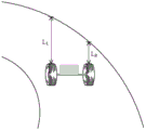
In the embodiment of the present invention, the first direction is a direction perpendicular to a line connecting the two wheels. As shown in fig. 4, the electronic device is located in the S-shaped path, and during the movement of the electronic device, the electronic device may touch the path edge obstacle at the front turn, and therefore, the electronic device needs to perform an adaptive turn according to the distance from the electronic device to the obstacle. Specifically, as shown in fig. 5, a first distance (L) of a first wheel from an obstacle in a first direction is monitoredL) And monitoring a second distance (L) of the second wheel from the obstacle in said first directionR)。
Step 102: comparing the magnitude of the first distance and the second distance.
The case where the first distance is greater than the second distance is shown in fig. 5, namely: l isL>LR. The case where the second distance is greater than the first distance is shown in figure 6,namely: l isR>LL。
Step 103: controlling a rotation parameter of the first wheel and/or the second wheel to cause the electronic device to rotate to the left if the first distance is greater than the second distance.
In the embodiment of the present invention, as shown in FIG. 5, if L isL>LRIf so, the electronic equipment needs to be controlled to turn left as a whole so as to avoid touching the obstacle. Specifically, the electronic device can be turned to the left as a whole by controlling the first wheel to be stationary and the second wheel to be advanced (corresponding to clockwise rotation). The electronic device can also be turned to the left as a whole by controlling the first wheel to move backwards (corresponding to counterclockwise rotation) and the second wheel to move forwards (corresponding to clockwise rotation).
In an embodiment of the invention, a rotation parameter of each of the two wheels is determined based on the first distance and the second distance, wherein the rotation parameter comprises at least one of: rotational speed, rotational acceleration.
Step 104: controlling a rotation parameter of the first wheel and/or the second wheel to cause the electronic device to rotate to the right if the first distance is less than the second distance.
In the embodiment of the present invention, as shown in FIG. 6, if L isR>LLIf so, the electronic equipment needs to be controlled to turn right integrally so as to avoid touching the obstacle. Specifically, the electronic device can be turned to the right as a whole by controlling the second wheel to be stationary and the first wheel to advance (corresponding to clockwise rotation). The electronic device can also be turned to the right as a whole by controlling the second wheel to go backwards (corresponding to counterclockwise rotation) and the first wheel to go forwards (corresponding to clockwise rotation).
In an embodiment of the invention, a rotation parameter of each of the two wheels is determined based on the first distance and the second distance, wherein the rotation parameter comprises at least one of: rotational speed, rotational acceleration.
In the embodiment of the invention, the first distance and the second distance are monitored in real time in the movement process of the electronic equipment, and the rotation parameters of two wheels in the electronic equipment are adjusted in time according to the first distance and the second distance to make adaptive turning so as to avoid touching obstacles.
Fig. 2 is a schematic flow chart diagram of a motion control method according to an embodiment of the present invention, as shown in fig. 2, the motion control method includes the following steps:
step 201: monitoring a first distance from a barrier body to a first wheel along a first direction, and monitoring a second distance from the barrier body to a second wheel along the first direction, wherein the first wheel and the second wheel are arranged on two sides of an electronic device.
In the embodiment of the invention, the electronic equipment can be mobile equipment such as a robot, a balance car and the like. The electronic device has two wheels, namely a first wheel and a second wheel, wherein the first wheel is a left wheel, the second wheel is a right wheel, and of course, the electronic device may further include a third wheel, and the third wheel is a universal wheel.
In the embodiment of the invention, the ultrasonic devices are respectively arranged on the two wheels in the electronic equipment, and the distance between the wheels and the front obstacle can be detected through the ultrasonic devices.
Here, the ultrasonic frequency of the ultrasonic device in the first wheel and the ultrasonic frequency of the ultrasonic device in the second wheel may be the same or different.
Of course, the device for detecting the distance is not limited to the ultrasonic device, and may be a laser radar or the like.
In the embodiment of the present invention, the first direction is a direction perpendicular to a line connecting the two wheels. As shown in fig. 4, the electronic device is located in the S-shaped path, and during the movement of the electronic device, the electronic device may touch the path edge obstacle at the front turn, and therefore, the electronic device needs to perform an adaptive turn according to the distance from the electronic device to the obstacle. Specifically, as shown in fig. 5, a first distance (L) of a first wheel from an obstacle in a first direction is monitoredL) And monitoring a second distance (L) of the second wheel from the obstacle in said first directionR)。
Step 202: acquiring the minimum value of the first distance and the second distance, judging whether the minimum value is greater than or equal to a preset length, and if so, executing step 203; if not, go to step 204.
Specifically, obtaining the minimum value of the first distance and the second distance may be according to the following formula: min (L)L,LR) And obtaining the result, wherein min represents the minimum value operation.
In an embodiment of the invention, the preset length is determined based on a radius of the first wheel and/or the second wheel. In one embodiment, the first wheel and the second wheel have the same radius, both R. The preset length may be set to 5 times R, i.e., 5R. Thus, min (L) needs to be judgedL,LR) Whether or not it is 5R or more. If min (L)L,LR) Not less than 5R, the electronic equipment is not very close to the obstacle, and the turning can be executed if min (L)L,LR) If the distance is less than 5R, the electronic equipment is very close to the obstacle, and the turning cannot be executed (the electronic equipment has the danger of touching).
Step 203: comparing the first distance with the second distance, and if the first distance is greater than the second distance, executing step 205; if the first distance is less than the second distance, step 206 is performed.
The case where the first distance is greater than the second distance is shown in fig. 5, namely: l isL>LR. The case where the second distance is greater than the first distance is shown in fig. 6, namely: l isR>LL。
In the embodiment of the invention, if LL=LRThen no turn need be performed but instead a forward motion is performed.
Step 204: and controlling the first wheel and/or the second wheel to rotate along a second direction until the minimum value is greater than or equal to the preset length, and executing step 203.
Here, the second direction is a wheel backward direction (corresponding to counterclockwise rotation). If min (L)L,LR) If < 5R, L needs to be controlledLIncrease and/or LRIncrease, i.e.: backing the first wheel or backing the second wheel or backing both wheels simultaneously until min (L)L,LR) And continuing to execute step 203 until the distance is larger than or equal to 5R, and comparing the first distance with the second distance.
Step 205: controlling a rotation parameter of the first wheel and/or the second wheel to cause the electronic device to rotate to the left.
In the embodiment of the present invention, as shown in FIG. 5, if L isL>LRIf so, the electronic equipment needs to be controlled to turn left as a whole so as to avoid touching the obstacle. Specifically, the electronic device can be turned to the left as a whole by controlling the first wheel to be stationary and the second wheel to be advanced (corresponding to clockwise rotation). The electronic device can also be turned to the left as a whole by controlling the first wheel to move backwards (corresponding to counterclockwise rotation) and the second wheel to move forwards (corresponding to clockwise rotation).
In an embodiment of the invention, a rotation parameter of each of the two wheels is determined based on the first distance and the second distance, wherein the rotation parameter comprises at least one of: rotational speed, rotational acceleration.
Step 206: controlling a rotation parameter of the first wheel and/or the second wheel to cause the electronic device to rotate to the right.
In the embodiment of the present invention, as shown in FIG. 6, if L isR>LLIf so, the electronic equipment needs to be controlled to turn right integrally so as to avoid touching the obstacle. Specifically, the electronic device can be turned to the right as a whole by controlling the second wheel to be stationary and the first wheel to advance (corresponding to clockwise rotation). The electronic device can also be turned to the right as a whole by controlling the second wheel to go backwards (corresponding to counterclockwise rotation) and the first wheel to go forwards (corresponding to clockwise rotation).
In an embodiment of the invention, a rotation parameter of each of the two wheels is determined based on the first distance and the second distance, wherein the rotation parameter comprises at least one of: rotational speed, rotational acceleration.
In the embodiment of the invention, the first distance and the second distance are monitored in real time in the movement process of the electronic equipment, and the rotation parameters of two wheels in the electronic equipment are adjusted in time according to the first distance and the second distance to make adaptive turning so as to avoid touching obstacles.
Fig. 3 is a schematic flow chart diagram of a motion control method according to an embodiment of the present invention, as shown in fig. 3, the motion control method includes the following steps:
step 301: monitoring a first distance from a barrier body to a first wheel along a first direction, and monitoring a second distance from the barrier body to a second wheel along the first direction, wherein the first wheel and the second wheel are arranged on two sides of an electronic device.
In the embodiment of the invention, the electronic equipment can be mobile equipment such as a robot, a balance car and the like. The electronic device has two wheels, namely a first wheel and a second wheel, wherein the first wheel is a left wheel, the second wheel is a right wheel, and of course, the electronic device may further include a third wheel, and the third wheel is a universal wheel.
In the embodiment of the invention, the ultrasonic devices are respectively arranged on the two wheels in the electronic equipment, and the distance between the wheels and the front obstacle can be detected through the ultrasonic devices.
Here, the ultrasonic frequency of the ultrasonic device in the first wheel and the ultrasonic frequency of the ultrasonic device in the second wheel may be the same or different.
Of course, the device for detecting the distance is not limited to the ultrasonic device, and may be a laser radar or the like.
In the embodiment of the present invention, the first direction is a direction perpendicular to a line connecting the two wheels. As shown in fig. 4, the electronic device is located in the S-shaped path, and during the movement of the electronic device, the electronic device may touch the path edge obstacle at the front turn, and therefore, the electronic device needs to perform an adaptive turn according to the distance from the electronic device to the obstacle. Specifically, as shown in fig. 5, a first distance (L) of a first wheel from an obstacle in a first direction is monitoredL) And monitoring a second distance (L) of the second wheel from the obstacle in said first directionR)。
Step 302: comparing the magnitude of the first distance and the second distance.
First distanceThe case of greater than the second distance is shown in fig. 5, namely: l isL>LR. The case where the second distance is greater than the first distance is shown in fig. 6, namely: l isR>LL。
Step 303: and if the first distance is greater than the second distance, controlling the first wheel to stop rotating, and controlling the second wheel to rotate along a third direction, so that the electronic equipment rotates to the left.
Here, the third direction is a wheel advancing direction (corresponding to clockwise rotation).
In the embodiment of the present invention, as shown in FIG. 5, if L isL>LRIf so, the electronic equipment needs to be controlled to turn left as a whole so as to avoid touching the obstacle. Specifically, the electronic device can be turned to the left as a whole by controlling the first wheel to be stationary and the second wheel to be advanced (corresponding to clockwise rotation).
In an embodiment of the invention, a rotation parameter of each of the two wheels is determined based on the first distance and the second distance, wherein the rotation parameter comprises at least one of: rotational speed, rotational acceleration.
For example: the first distance is 30R, the second distance is 10R, and at this time, min (30R, 10R) ═ 10R > 5R, where 5R is a preset length and represents that turning is required, and since 30R is greater than 10R, turning to the left is required, the left wheel is controlled to be stationary, and the right wheel is rotated forward (corresponding to clockwise rotation) to turn the whole electronic device to the left. The specific parameters of the rotation can be determined according to 30R and 10R, and generally, the larger the difference between the first distance and the second distance, the larger the rotation angle.
Of course, the first wheel may be controlled to rotate in the second direction, and the second wheel may be controlled to rotate in the third direction, so that the electronic device rotates to the left. Namely: the left wheel retreats and the right wheel advances to realize leftward rotation.
Step 304: and if the first distance is smaller than the second distance, controlling the second wheel to stop rotating, and controlling the first wheel to rotate along a third direction, so that the electronic equipment rotates to the right.
In the embodiment of the present invention, as shown in FIG. 6, if L isR>LLIf so, the electronic equipment needs to be controlled to turn right integrally so as to avoid touching the obstacle. Specifically, the electronic device can be turned to the right as a whole by controlling the second wheel to be stationary and the first wheel to advance (corresponding to clockwise rotation).
In an embodiment of the invention, a rotation parameter of each of the two wheels is determined based on the first distance and the second distance, wherein the rotation parameter comprises at least one of: rotational speed, rotational acceleration.
For example: the second distance is 30R, the first distance is 10R, and at this time, min (30R, 10R) ═ 10R > 5R, where 5R is a preset length and represents that turning is required, and since 30R is greater than 10R, turning to the right is required, the right wheel is controlled not to move, and the left wheel rotates forward (corresponding to clockwise rotation) to turn the whole electronic device to the right. The specific parameters of the rotation can be determined according to 30R and 10R, and generally, the larger the difference between the first distance and the second distance, the larger the rotation angle.
Of course, the second wheel may be controlled to rotate in the second direction, and the first wheel may be controlled to rotate in the third direction, so that the electronic device may rotate to the right. Namely: the left wheel moves forward, the right wheel moves backward, and the right wheel rotates rightwards.
In the embodiment of the invention, the first distance and the second distance are monitored in real time in the movement process of the electronic equipment, and the rotation parameters of two wheels in the electronic equipment are adjusted in time according to the first distance and the second distance to make adaptive turning so as to avoid touching obstacles.
Fig. 7 is a first schematic structural component diagram of an electronic device according to an embodiment of the present invention, and as shown in fig. 7, the electronic device includes: a first wheel 71 and a second wheel 72, wherein the first wheel 71 and the second wheel 72 are arranged on two sides of the electronic device;
a sensor 73 for monitoring a first distance of the first wheel 71 from the obstacle in a first direction and for monitoring a second distance of the second wheel 72 from the obstacle in said first direction;
a processor 74 for comparing the magnitudes of the first and second distances; controlling a rotation parameter of the first wheel 71 and/or the second wheel 72 to cause the electronic device to rotate to the left if the first distance is greater than the second distance; controlling a rotation parameter of the first wheel 71 and/or the second wheel 72 to cause the electronic device to rotate to the right if the first distance is less than the second distance.
In an embodiment, the processor 74 is further configured to obtain a minimum value of the first distance and the second distance, and determine whether the minimum value is greater than or equal to a preset length; and if the minimum value is larger than or equal to the preset length, comparing the first distance with the second distance.
In one embodiment, the processor 74 is further configured to control the first wheel 71 and/or the second wheel 72 to rotate in the second direction if the minimum value is less than the preset length, until the minimum value is greater than or equal to the preset length.
In one embodiment, the processor 74 is further configured to control the first wheel 71 to stop rotating, and control the second wheel 72 to rotate in a third direction, so that the electronic device rotates to the left; alternatively, the first wheel 71 is controlled to rotate in the second direction, and the second wheel 72 is controlled to rotate in the third direction, so that the electronic device rotates to the left.
In one embodiment, the processor 74 is further configured to control the second wheel 72 to stop rotating, and control the first wheel 71 to rotate in a third direction, so that the electronic device rotates to the right; alternatively, the second wheel 72 is controlled to rotate in the second direction, and the first wheel 71 is controlled to rotate in the third direction, so that the electronic device rotates to the right.
It will be appreciated by those skilled in the art that the functions implemented by the units in the electronic device shown in fig. 7 can be understood with reference to the foregoing description of the motion control method.
Fig. 8 is a schematic structural composition diagram of an electronic device according to an embodiment of the present invention, and as shown in fig. 8, the electronic device includes: a first wheel 81 and a second wheel 82, the first wheel 81 and the second wheel 82 being disposed on both sides of the electronic device;
a sensor 83 for monitoring a first distance of the first wheel 81 from the obstacle in a first direction and for monitoring a second distance of the second wheel 82 from the obstacle in said first direction;
a processor 84 for comparing the magnitudes of the first and second distances; if the first distance is greater than the second distance, controlling a rotation parameter of the first wheel 81 and/or the second wheel 82 to cause the electronic device to rotate to the left; if the first distance is smaller than the second distance, controlling a rotation parameter of the first wheel 81 and/or the second wheel 82 to cause the electronic device to rotate to the right.
In an embodiment, the processor 84 is further configured to obtain a minimum value of the first distance and the second distance, and determine whether the minimum value is greater than or equal to a preset length; and if the minimum value is larger than or equal to the preset length, comparing the first distance with the second distance.
In one embodiment, the processor 84 is further configured to control the first wheel 81 and/or the second wheel 82 to rotate in the second direction if the minimum value is smaller than the preset length, until the minimum value is greater than or equal to the preset length and stops rotating.
In one embodiment, the processor 84 is further configured to control the first wheel 81 to stop rotating, and control the second wheel 82 to rotate in a third direction, so that the electronic device rotates to the left; alternatively, the first wheel 81 is controlled to rotate in the second direction, and the second wheel 82 is controlled to rotate in the third direction, so that the electronic device rotates to the left.
In one embodiment, the processor 84 is further configured to control the second wheel 82 to stop rotating, and control the first wheel 81 to rotate in a third direction, so that the electronic device rotates to the right; alternatively, the second wheel 82 is controlled to rotate in the second direction, and the first wheel 81 is controlled to rotate in the third direction, so that the electronic device rotates to the right.
In one embodiment, the electronic device further comprises: and the memory 85 is used for storing historical rotation records of the first wheel and the second wheel, so that the electronic equipment can perform reverse movement according to the historical rotation records, and the electronic equipment can be conveniently withdrawn.
Here, the contents of the history rotation record may include: the corresponding rotational speed and acceleration at each moment.
The technical schemes described in the embodiments of the present invention can be combined arbitrarily without conflict.
In the embodiments provided in the present invention, it should be understood that the disclosed method and intelligent device may be implemented in other ways. The above-described device embodiments are merely illustrative, for example, the division of the unit is only a logical functional division, and there may be other division ways in actual implementation, such as: multiple units or components may be combined, or may be integrated into another system, or some features may be omitted, or not implemented. In addition, the coupling, direct coupling or communication connection between the components shown or discussed may be through some interfaces, and the indirect coupling or communication connection between the devices or units may be electrical, mechanical or other forms.
The units described as separate parts may or may not be physically separate, and parts displayed as units may or may not be physical units, that is, may be located in one place, or may be distributed on a plurality of network units; some or all of the units can be selected according to actual needs to achieve the purpose of the solution of the embodiment.
In addition, all the functional units in the embodiments of the present invention may be integrated into one second processing unit, or each unit may be separately regarded as one unit, or two or more units may be integrated into one unit; the integrated unit can be realized in a form of hardware, or in a form of hardware plus a software functional unit.
The above description is only for the specific embodiments of the present invention, but the scope of the present invention is not limited thereto, and any person skilled in the art can easily conceive of the changes or substitutions within the technical scope of the present invention, and all the changes or substitutions should be covered within the scope of the present invention.
Claims (8)
1. A method of motion control, the method comprising:
monitoring a first distance from a first wheel to an obstacle along a first direction, and monitoring a second distance from a second wheel to the obstacle along the first direction, wherein the first wheel and the second wheel are arranged on two sides of an electronic device; the first direction is a direction perpendicular to a connecting line of the first wheel and the second wheel;
acquiring the minimum value of the first distance and the second distance, and judging whether the minimum value is greater than or equal to a preset length;
if the minimum value is smaller than a preset length, controlling the first wheel and/or the second wheel to rotate along a second direction until the minimum value is larger than or equal to the preset length and stopping rotating; wherein the second direction comprises at least a wheel-back direction;
comparing the magnitude of the first distance and the second distance;
if the first distance is greater than the second distance, controlling a rotation parameter of the first wheel and/or the second wheel to enable the electronic device to rotate to the left;
controlling a rotation parameter of the first wheel and/or the second wheel to cause the electronic device to rotate to the right if the first distance is less than the second distance.
2. The motion control method of claim 1, further comprising:
and if the minimum value is larger than or equal to the preset length, comparing the first distance with the second distance.
3. The motion control method according to claim 1, wherein the controlling the rotation parameter of the first wheel and/or the second wheel to cause the electronic device to rotate to the left comprises:
controlling the first wheel to stop rotating and controlling the second wheel to rotate along a third direction, so that the electronic equipment rotates to the left; alternatively, the first and second electrodes may be,
the first wheel is controlled to rotate along a second direction, and the second wheel is controlled to rotate along a third direction, so that the electronic equipment rotates leftwards.
4. The motion control method according to claim 1, wherein the controlling the rotation parameter of the first wheel and/or the second wheel to cause the electronic device to rotate to the right comprises:
controlling the second wheel to stop rotating, and controlling the first wheel to rotate along a third direction, so that the electronic equipment rotates to the right; alternatively, the first and second electrodes may be,
and controlling the second wheel to rotate along a second direction, and controlling the first wheel to rotate along a third direction, so that the electronic equipment rotates to the right.
5. An electronic device, characterized in that the electronic device comprises: the first wheel and the second wheel are arranged on two sides of the electronic equipment;
a sensor for monitoring a first distance of a first wheel from an obstacle along a first direction and monitoring a second distance of a second wheel from the obstacle along the first direction; the first direction is a direction perpendicular to a connecting line of the first wheel and the second wheel;
the processor is used for acquiring the minimum value of the first distance and the second distance and judging whether the minimum value is greater than or equal to a preset length; if the minimum value is smaller than a preset length, controlling the first wheel and/or the second wheel to rotate along a second direction until the minimum value is larger than or equal to the preset length and stopping rotating; wherein the second direction comprises at least a wheel-back direction; comparing the magnitude of the first distance and the second distance; if the first distance is greater than the second distance, controlling a rotation parameter of the first wheel and/or the second wheel to enable the electronic device to rotate to the left; controlling a rotation parameter of the first wheel and/or the second wheel to cause the electronic device to rotate to the right if the first distance is less than the second distance.
6. The electronic device of claim 5, wherein the processor is further configured to compare the first distance and the second distance if the minimum value is greater than or equal to the preset length.
7. The electronic device of claim 5, wherein the processor is further configured to control the first wheel to stop rotating and the second wheel to rotate in a third direction, so that the electronic device rotates to the left; or the first wheel is controlled to rotate along a second direction, and the second wheel is controlled to rotate along a third direction, so that the electronic equipment rotates leftwards.
8. The electronic device of claim 5, wherein the processor is further configured to control the second wheel to stop rotating and the first wheel to rotate in a third direction, so that the electronic device rotates to the right; or the second wheel is controlled to rotate along a second direction, and the first wheel is controlled to rotate along a third direction, so that the electronic equipment rotates to the right.
Priority Applications (1)
| Application Number | Priority Date | Filing Date | Title |
|---|---|---|---|
| CN201710151346.5A CN106980314B (en) | 2017-03-14 | 2017-03-14 | Motion control method and electronic equipment |
Applications Claiming Priority (1)
| Application Number | Priority Date | Filing Date | Title |
|---|---|---|---|
| CN201710151346.5A CN106980314B (en) | 2017-03-14 | 2017-03-14 | Motion control method and electronic equipment |
Publications (2)
| Publication Number | Publication Date |
|---|---|
| CN106980314A CN106980314A (en) | 2017-07-25 |
| CN106980314B true CN106980314B (en) | 2020-11-20 |
Family
ID=59338935
Family Applications (1)
| Application Number | Title | Priority Date | Filing Date |
|---|---|---|---|
| CN201710151346.5A Active CN106980314B (en) | 2017-03-14 | 2017-03-14 | Motion control method and electronic equipment |
Country Status (1)
| Country | Link |
|---|---|
| CN (1) | CN106980314B (en) |
Citations (2)
| Publication number | Priority date | Publication date | Assignee | Title |
|---|---|---|---|---|
| WO2015166705A1 (en) * | 2014-04-28 | 2015-11-05 | 日立建機株式会社 | Road-shoulder-detecting system and transportation vehicle for mining |
| KR20160070467A (en) * | 2014-12-10 | 2016-06-20 | 재단법인대구경북과학기술원 | A multi robot system for avoding obstacle and a method using switching formation strategy for obstable avoidandce |
Family Cites Families (6)
| Publication number | Priority date | Publication date | Assignee | Title |
|---|---|---|---|---|
| CN204169779U (en) * | 2014-11-07 | 2015-02-25 | 王宁静 | Clean robot |
| KR101712399B1 (en) * | 2014-11-25 | 2017-03-06 | 현대모비스 주식회사 | Obstacle display method of vehicle |
| JP6553350B2 (en) * | 2014-11-26 | 2019-07-31 | アイシン精機株式会社 | Moving body |
| CN205530058U (en) * | 2016-01-25 | 2016-08-31 | 河南隆源电动车有限公司 | Garbage sweeper |
| CN105620474B (en) * | 2016-01-26 | 2019-02-19 | 吉林大学 | A kind of four-wheel wheel hub driving electric car active barrier-avoiding method with multi-mode |
| CN106272425B (en) * | 2016-09-07 | 2018-12-18 | 上海木木机器人技术有限公司 | Barrier-avoiding method and robot |
-
2017
- 2017-03-14 CN CN201710151346.5A patent/CN106980314B/en active Active
Patent Citations (2)
| Publication number | Priority date | Publication date | Assignee | Title |
|---|---|---|---|---|
| WO2015166705A1 (en) * | 2014-04-28 | 2015-11-05 | 日立建機株式会社 | Road-shoulder-detecting system and transportation vehicle for mining |
| KR20160070467A (en) * | 2014-12-10 | 2016-06-20 | 재단법인대구경북과학기술원 | A multi robot system for avoding obstacle and a method using switching formation strategy for obstable avoidandce |
Also Published As
| Publication number | Publication date |
|---|---|
| CN106980314A (en) | 2017-07-25 |
Similar Documents
| Publication | Publication Date | Title |
|---|---|---|
| US10850742B2 (en) | Safety stoppage device and autonomous road vehicle equipped therewith | |
| CN107792079B (en) | Autonomous vehicle with path prediction | |
| US20200290646A1 (en) | Systems and methods for vehicle steering control | |
| KR101503418B1 (en) | Semiautomatic parking machine | |
| US20190299978A1 (en) | Automatic Navigation Using Deep Reinforcement Learning | |
| US11084490B2 (en) | Apparatus and method for controlling drive of vehicle | |
| CN110015339B (en) | Rack bar limit condition detection and corresponding steering wheel torque feedback for steer-by-wire systems | |
| WO2015097511A1 (en) | Vehicle surrounding situation estimation device | |
| JP6997293B2 (en) | Autonomous traveling work equipment and control system | |
| JP6463571B1 (en) | Vehicle control device | |
| JP7230777B2 (en) | vehicle control system | |
| CN110341786B (en) | Disturbance feedforward compensation for position control in steering system | |
| JP2016224038A5 (en) | ||
| US20190193269A1 (en) | Robot control system and method of controlling a robot | |
| US20220001857A1 (en) | Parking assistance device, vehicle, parking assistance method, and non-transitory computer-readable medium | |
| WO2018198530A1 (en) | Parking assistance device | |
| CN115303262A (en) | Vehicle control method, device, terminal device and computer readable storage medium | |
| JP7243095B2 (en) | vehicle controller | |
| CN106980314B (en) | Motion control method and electronic equipment | |
| JP5439552B2 (en) | Robot system | |
| CN110083158B (en) | Method and equipment for determining local planning path | |
| KR102509852B1 (en) | Control device and method | |
| CN108121341B (en) | Automatic parking method and system for balance car fleet | |
| CN109073504B (en) | Cabin door detection method and system, mobile platform and plant protection machine | |
| CN112641390A (en) | Method for getting rid of difficulties of sweeping robot |
Legal Events
| Date | Code | Title | Description |
|---|---|---|---|
| PB01 | Publication | ||
| PB01 | Publication | ||
| SE01 | Entry into force of request for substantive examination | ||
| SE01 | Entry into force of request for substantive examination | ||
| GR01 | Patent grant | ||
| GR01 | Patent grant |