CN1069771C - Magnetic recording/reproducing apparatus and control method thereof - Google Patents

Magnetic recording/reproducing apparatus and control method thereof Download PDF

Info

Publication number
CN1069771C
CN1069771C CN95103514A CN95103514A CN1069771C CN 1069771 C CN1069771 C CN 1069771C CN 95103514 A CN95103514 A CN 95103514A CN 95103514 A CN95103514 A CN 95103514A CN 1069771 C CN1069771 C CN 1069771C
Authority
CN
China
Prior art keywords
magnetic head
magnetic
servo
transcriber
magnetic recording
Prior art date
Legal status (The legal status is an assumption and is not a legal conclusion. Google has not performed a legal analysis and makes no representation as to the accuracy of the status listed.)
Expired - Lifetime
Application number
CN95103514A
Other languages
Chinese (zh)
Other versions
CN1115069A (en
Inventor
盐谷秋夫
秦裕二
Current Assignee (The listed assignees may be inaccurate. Google has not performed a legal analysis and makes no representation or warranty as to the accuracy of the list.)
HGST Japan Ltd
Original Assignee
Hitachi Ltd
Priority date (The priority date is an assumption and is not a legal conclusion. Google has not performed a legal analysis and makes no representation as to the accuracy of the date listed.)
Filing date
Publication date
Application filed by Hitachi Ltd filed Critical Hitachi Ltd
Publication of CN1115069A publication Critical patent/CN1115069A/en
Application granted granted Critical
Publication of CN1069771C publication Critical patent/CN1069771C/en
Anticipated expiration legal-status Critical
Expired - Lifetime legal-status Critical Current

Links

Images

Classifications

    • GPHYSICS
    • G11INFORMATION STORAGE
    • G11BINFORMATION STORAGE BASED ON RELATIVE MOVEMENT BETWEEN RECORD CARRIER AND TRANSDUCER
    • G11B5/00Recording by magnetisation or demagnetisation of a record carrier; Reproducing by magnetic means; Record carriers therefor
    • G11B5/48Disposition or mounting of heads or head supports relative to record carriers ; arrangements of heads, e.g. for scanning the record carrier to increase the relative speed
    • G11B5/54Disposition or mounting of heads or head supports relative to record carriers ; arrangements of heads, e.g. for scanning the record carrier to increase the relative speed with provision for moving the head into or out of its operative position or across tracks
    • G11B5/55Track change, selection or acquisition by displacement of the head
    • G11B5/5521Track change, selection or acquisition by displacement of the head across disk tracks
    • G11B5/5526Control therefor; circuits, track configurations or relative disposition of servo-information transducers and servo-information tracks for control thereof
    • G11B5/553Details
    • GPHYSICS
    • G11INFORMATION STORAGE
    • G11BINFORMATION STORAGE BASED ON RELATIVE MOVEMENT BETWEEN RECORD CARRIER AND TRANSDUCER
    • G11B19/00Driving, starting, stopping record carriers not specifically of filamentary or web form, or of supports therefor; Control thereof; Control of operating function ; Driving both disc and head
    • G11B19/02Control of operating function, e.g. switching from recording to reproducing
    • G11B19/04Arrangements for preventing, inhibiting, or warning against double recording on the same blank or against other recording or reproducing malfunctions
    • GPHYSICS
    • G11INFORMATION STORAGE
    • G11BINFORMATION STORAGE BASED ON RELATIVE MOVEMENT BETWEEN RECORD CARRIER AND TRANSDUCER
    • G11B5/00Recording by magnetisation or demagnetisation of a record carrier; Reproducing by magnetic means; Record carriers therefor
    • G11B5/40Protective measures on heads, e.g. against excessive temperature 
    • GPHYSICS
    • G11INFORMATION STORAGE
    • G11BINFORMATION STORAGE BASED ON RELATIVE MOVEMENT BETWEEN RECORD CARRIER AND TRANSDUCER
    • G11B5/00Recording by magnetisation or demagnetisation of a record carrier; Reproducing by magnetic means; Record carriers therefor
    • G11B5/48Disposition or mounting of heads or head supports relative to record carriers ; arrangements of heads, e.g. for scanning the record carrier to increase the relative speed
    • G11B5/54Disposition or mounting of heads or head supports relative to record carriers ; arrangements of heads, e.g. for scanning the record carrier to increase the relative speed with provision for moving the head into or out of its operative position or across tracks
    • G11B5/55Track change, selection or acquisition by displacement of the head
    • G11B5/5504Track change, selection or acquisition by displacement of the head across tape tracks
    • G11B5/5508Control circuits therefor
    • GPHYSICS
    • G11INFORMATION STORAGE
    • G11BINFORMATION STORAGE BASED ON RELATIVE MOVEMENT BETWEEN RECORD CARRIER AND TRANSDUCER
    • G11B5/00Recording by magnetisation or demagnetisation of a record carrier; Reproducing by magnetic means; Record carriers therefor
    • G11B5/48Disposition or mounting of heads or head supports relative to record carriers ; arrangements of heads, e.g. for scanning the record carrier to increase the relative speed
    • G11B5/54Disposition or mounting of heads or head supports relative to record carriers ; arrangements of heads, e.g. for scanning the record carrier to increase the relative speed with provision for moving the head into or out of its operative position or across tracks
    • G11B5/55Track change, selection or acquisition by displacement of the head
    • G11B5/5521Track change, selection or acquisition by displacement of the head across disk tracks
    • G11B5/5526Control therefor; circuits, track configurations or relative disposition of servo-information transducers and servo-information tracks for control thereof
    • G11B5/553Details
    • G11B5/5547"Seek" control and circuits therefor
    • GPHYSICS
    • G11INFORMATION STORAGE
    • G11BINFORMATION STORAGE BASED ON RELATIVE MOVEMENT BETWEEN RECORD CARRIER AND TRANSDUCER
    • G11B5/00Recording by magnetisation or demagnetisation of a record carrier; Reproducing by magnetic means; Record carriers therefor
    • G11B5/48Disposition or mounting of heads or head supports relative to record carriers ; arrangements of heads, e.g. for scanning the record carrier to increase the relative speed
    • G11B5/58Disposition or mounting of heads or head supports relative to record carriers ; arrangements of heads, e.g. for scanning the record carrier to increase the relative speed with provision for moving the head for the purpose of maintaining alignment of the head relative to the record carrier during transducing operation, e.g. to compensate for surface irregularities of the latter or for track following
    • G11B5/584Disposition or mounting of heads or head supports relative to record carriers ; arrangements of heads, e.g. for scanning the record carrier to increase the relative speed with provision for moving the head for the purpose of maintaining alignment of the head relative to the record carrier during transducing operation, e.g. to compensate for surface irregularities of the latter or for track following for track following on tapes
    • GPHYSICS
    • G11INFORMATION STORAGE
    • G11BINFORMATION STORAGE BASED ON RELATIVE MOVEMENT BETWEEN RECORD CARRIER AND TRANSDUCER
    • G11B5/00Recording by magnetisation or demagnetisation of a record carrier; Reproducing by magnetic means; Record carriers therefor
    • G11B5/48Disposition or mounting of heads or head supports relative to record carriers ; arrangements of heads, e.g. for scanning the record carrier to increase the relative speed
    • G11B5/58Disposition or mounting of heads or head supports relative to record carriers ; arrangements of heads, e.g. for scanning the record carrier to increase the relative speed with provision for moving the head for the purpose of maintaining alignment of the head relative to the record carrier during transducing operation, e.g. to compensate for surface irregularities of the latter or for track following
    • G11B5/596Disposition or mounting of heads or head supports relative to record carriers ; arrangements of heads, e.g. for scanning the record carrier to increase the relative speed with provision for moving the head for the purpose of maintaining alignment of the head relative to the record carrier during transducing operation, e.g. to compensate for surface irregularities of the latter or for track following for track following on disks
    • G11B5/59683Disposition or mounting of heads or head supports relative to record carriers ; arrangements of heads, e.g. for scanning the record carrier to increase the relative speed with provision for moving the head for the purpose of maintaining alignment of the head relative to the record carrier during transducing operation, e.g. to compensate for surface irregularities of the latter or for track following for track following on disks for magnetoresistive heads
    • GPHYSICS
    • G11INFORMATION STORAGE
    • G11BINFORMATION STORAGE BASED ON RELATIVE MOVEMENT BETWEEN RECORD CARRIER AND TRANSDUCER
    • G11B5/00Recording by magnetisation or demagnetisation of a record carrier; Reproducing by magnetic means; Record carriers therefor
    • G11B2005/0002Special dispositions or recording techniques
    • G11B2005/0005Arrangements, methods or circuits
    • G11B2005/001Controlling recording characteristics of record carriers or transducing characteristics of transducers by means not being part of their structure
    • G11B2005/0013Controlling recording characteristics of record carriers or transducing characteristics of transducers by means not being part of their structure of transducers, e.g. linearisation, equalisation
    • G11B2005/0016Controlling recording characteristics of record carriers or transducing characteristics of transducers by means not being part of their structure of transducers, e.g. linearisation, equalisation of magnetoresistive transducers
    • G11B2005/0018Controlling recording characteristics of record carriers or transducing characteristics of transducers by means not being part of their structure of transducers, e.g. linearisation, equalisation of magnetoresistive transducers by current biasing control or regulation

Landscapes

  • Magnetic Heads (AREA)
  • Recording Or Reproducing By Magnetic Means (AREA)
  • Adjustment Of The Magnetic Head Position Track Following On Tapes (AREA)

Abstract

When a magnetic recording and reproducing apparatus is in a waiting state, feedback control for positioning the carriage is released, and a supply of a sense current to the magnetoresistive effect element of the MR magnetic head is adjusted so as to prolong the life of the MR magnetic head. When the interface and control circuit recognizes that there is no order from the host computer and that the magnetic recording and reproducing apparatus is in a wait state, the servo control circuit releases the feedback control for positioning the head. A mode, etc. selection control circuit controls the recording/reproduction amplifier so as not to supply a sense current to the magnetoresistive effect element of the MR magnetic head so as to prolong the life of the magnetic head.

Description

Magnetic recorder/reproducer and control method thereof
The present invention relates to a magnetic recording and a transcriber that the magnetic head group (MR magnetic head group) that comprises magneto-resistance effect element (MR element) has been installed, the location technology in magnetic recording and the transcriber particularly, it is used for making magnetic head to search a purpose magnetic track (following action for), begins to shift to a purpose magnetic track (searching action for) then.
As one for increasing the technology that track density improves the location accuracy of magnetic head group, have the data track servo-drive system (being also referred to as " data surface control system ") that is recorded in the locating information on the magnetic recording media data surface before using.When wanting that the MR head technology is applied to this data track servo-drive system technology, must improve the permanance of MR magnetic head group.
This point will be described in detail in detail.
If improve the recording density of magnetic recording and transcriber, to reduce the magnetic transition zone of unit area on the magnetic medium inevitably.This means the width (perpendicular to the distance of a magnetic head reach direction on the magnetic track) that will reduce every magnetic track.Therefore, the reproduction of magnetic head output has reduced.A kind of practical measure that prevents that this reproduction output from reducing is the sensitivity that improves magnetic head.Under this condition, the MR magnetic head that comprises a magneto-resistance effect element (MR element) comes into operation, and it is a reading head for reading the magnetic transition zone.
As the device that is used to improve magnetic head sensitivity,, there is following technical matters if attempt obtains big reproduction output by loading a big current sensor for the MR element.
Usually, the current sensor intensity of MR magnetic head is very high, and nearly 10 7A/m 2, so that MR component life shortens; For example, the electronics drift taking place in the material of MR element or lead, cause the rising of temperature to aggravate electron drift again, causes component wear at last.
In order to improve track density, must improve the bearing accuracy of magnetic head.Why Here it is uses the reason of data track servo-drive system.In data track servo-drive system technology, the locating information of service recorder on data surface.Being used in combination of data track servo-drive system technology and MR magnetic head produced following technical matters.
Usually, magnetic track of magnetic head search must be carried out one and follow action.In the data track servo-drive system technology, must reproduce the locating information that is recorded in the sector head position continuously with magnetic head, the sector obtains by magnetic track is divided into secter pat.After data were reproduced by magnetic head, same magnetic head continued one and follows action and reproduce locating information simultaneously up to next record or reproduce order and send.In the magnetic recording and transcriber of the low reproduction frequency of a use, some times of cost before be everlasting next record or reproduction order provide, the result causes the accumulation of MR magnetic head to prolong service time, comprising reproducing locating information.This is the directly threat that the MR head life is shortened.
An object of the present invention is, when magnetic recording and transcriber are in wait when principal computer receives a data visit order, the load time of the magneto-resistance effect element current sensor by shortening the MR magnetic head prolongs the life-span of MR magnetic head.
In the technology that is used for prolonging the MR head life, a kind of technology as being proposed at the open No.5-226850 (applying on September 13rd, 1993) of Jap.P. is arranged, it is used for control head positioning time so that use the accumulated time length of each MR magnetic head to fix, this accumulated time be positioning time, data reproduction time etc. and.Yet in the present invention that this patent is used, problem above-mentioned is solved by following public technology.
Principal feature of the present invention is when magnetic recording and transcriber are in waiting status, and the conduction time that is reduced to the MR magnetic head is sought the prolongation of start time to remedy the MR magnetic head.Attach, the explanation of for example using magnetic tape equipment of the present invention or disk set has the following:
1) if control magnetic track servo (or control surface is a servo) control system is provided, before seeking the action beginning, carries out initialization (RTZ action: flyback action) by the magnetic head that moves on to assigned address; And
2), when seeking the action recovery for one, read track positional information if the data surface servo-control system is provided.
Therefore, even the prolongation of start time has taken place to seek, there are not much problems when magnetic recording and transcriber are in waiting status yet.Should note in the data surface servo control technique, can adopting the RTZ action.
In particular, first feature of the present invention is in magnetic recording that has the MR magnetic head and transcriber, when principal computer did not send data access command, FEEDBACK CONTROL (closed-loop control) circuit that is used for head position was cut off so that not to the magneto-resistance effect element transmission current sensor of MR magnetic head.
Second feature of the present invention is in magnetic recording that has the MR magnetic head and transcriber, and when principal computer did not send a data access command, the servo-information sampling period prolonged thereby reduced the conduction time to the MR magnetic head.Degenerating of head position precision can be compensated by the technical requirement of magnetic recording and transcriber.
The 3rd feature of the present invention is when magnetic recording that has the MR magnetic head and a sky searching of transcriber execution action, simultaneously not from higher level equipment forward data visit order, then carrying out empty a searching moves, do not export and do not use, and do not have sensing signal to be loaded into the MR element from the signal of MR magnetic head.In addition, fixing voltage or power supply are loaded into the device that is used to locate the MR magnetic head with fixing interval, as a drive unit or voice coil motor.
Notice that alleged one is emptyly sought action and is meant when magnetic head continuous positioning during a specific track here, partly adhere to and grow at the sliding shoe of magnetic head that magnetic recording and transcriber are carried out a searching alone and moved in order to prevent dust.This is sought to move also can be performed and is used for other purpose.
Now the effect that is obtained by the top scheme that proposes will be described.
Give one example, in a disk set, when principal computer is visited, the time of command execution,, reproduce or a searching action as record, be longer than the stand-by period (holding state) far away, so do not continue because principal computer visits to follow to move therebetween.On the other hand, in magnetic tape equipment, when higher level equipment was visited, used tape rotation time (following action therebetween up to the assigned address that arrives record or reproduce) was long more a lot of than the command execution time (executive logging or reproduction therebetween or a searching action).
In this holding state, if being transferred to the MR element constantly, current sensor is used to follow the positioning signal of action with reproduction, and tape rotates, or empty the searching, and this will greatly influence the life-span of magneto-resistance effect element.Therefore, when disk set be in principal computer do not have the visit waiting status the time, if follow action, tape rotates or empty the searching carried out by device above-mentioned, then be zero or control to minimum, can prolong the life-span of MR element by the time decreased that the magneto-resistance effect element to the MR magnetic head is applied current sensor.
Fig. 1 illustrates the main configuration of the disk set of first kind of embodiment according to the present invention;
Fig. 2 illustrates the main configuration of the magnetic tape equipment of second kind of embodiment according to the present invention;
Fig. 3 is the process flow diagram of a kind of method of servo-controlling in the embodiment of the present invention;
Fig. 4 is the process flow diagram of second kind of method of servo-controlling in the embodiment of the present invention;
Fig. 5 is the process flow diagram of the third method of servo-controlling in the embodiment of the present invention.
A) first kind of embodiment:
Fig. 1 has provided the main configuration of the disk set of first kind of embodiment according to the present invention.Main configuration comprises one or more disks 1, MR magnetic head 2 (the MR magnetic head uses magneto-resistance effect element to constitute a read-only synthetic magnetic head) corresponding to the disk number, a carriage 3, a voice coil motor 4, recording 5 with transmission current sensor to MR magnetic head function, selection circuit 6 such as a kind of pattern are used for control model and select, record or reproduction are selected and magnetic head is selected a tracer signal generator circuit 7, one is reproduced selection circuit 8,10, one interfaces of 9, one servosignal reproducing circuits of a data-signal reproducing circuit and control circuit 11, a servo control circuit 12 and a power amplifier 13.
In Fig. 1, carriage 3 and voice coil motor 4 are shown as linear actuating device, but the present invention can be used for comprising in the equipment of rotating driving device equally, and this rotating driving device is widely used in the small disc apparatus.
Usually at record with reproduce in the operation, interface and control circuit 11, receive an order from principal computer 14 after, sends a recoding/reproduction control command 15 to selection control circuits 6 such as patterns.And interface and control circuit 11 send a servocontrol order to servo control circuit 12.Selection control circuits 6 such as pattern judge whether that an operation of recording or a reproducing movement are by 15 execution of a recoding/reproduction control command, and send a head select signal, the signal 17 of selecting circuit 8 is reproduced in 16, one controls of the signal of a controlling recording/reproduction amplifier 5.
When recorded information, tracer signal generator circuit 7 receives the data that will be recorded that principal computer sends by interface and control circuit 11, and data are converted to a tracer signal so that signal can be recorded in a purpose magnetic track of disk 1.
When information reproduction, recording 5 is by the destination data on MR magnetic head 2 reading disk 1, head select signal and be used for the signal 16 of controlling recording/reproduction amplifier 5.Reproduce and select circuit 8 to use the signal of control circuit 8 to become a servosignal and a data-modulation signal from recording 5 intercept signals.Data-signal reproducing circuit 9 is from by reproduce selecting data-signal of demodulation circuit 8 selected data-modulation signals, and this data-signal is sent to principal computer by interface and control circuit 11.Servosignal reproducing circuit 10 produces one and is used for servo-controlled position signalling from reproduce selection circuit 8 selected servosignals.Servo control circuit 12 produces a signal that is used for the purpose magnetic track is sought or followed action from the position signalling that servosignal reproducing circuit 10 is produced, therefore the MR magnetic head can pass through power amplifier 13, the signal that voice coil motor 4 and carriage 3 send accurately is positioned on the purpose magnetic track.
Operation when telling about principal computer below and not connecting (be not a record or reproduce operation).
Interface joins in the servocontrol order 19 that sends to servo control circuit 12 with the information that control circuit 11 not is connected principal computer.Therefore, the current location when servo control circuit 12 memory stops servocontrol, and send one and stop servo-controlled signal 18 and select in the control circuit 6 to pattern etc.Selection control circuits such as pattern 6 send a signal to recording 5 with instruct it to stop to load current sensor to magneto-resistance effect element (MR element) to stop the operation of MR magnetic head 2.The result is that servocontrol stops, and carriage 3 enters a kind of free state that is not subjected to positioning control.
Next, when interface and control circuit 11 when principal computer receives a bind command, circuit 11 joins the connected signal of indication principal computer in the servo-control signal that sends to servo control circuit 12.Servo control circuit 12 sends one and recovers servo-controlled signal 18 and select control circuit 6 to recover servocontrol to pattern etc.In order to recover the operation of MR magnetic head 2, selection circuit such as pattern 6 send a signal to recording 5 to instruct its loading current sensor to magneto-resistance effect element and read a servosignal.Servo control circuit 12 is reorientated carriage in the position of memory, and handles an order from principal computer.
The scheme that use proposes above, on the basis of doing to estimate by consideration whole magnetic disk apparatus function, the conduction time that shortens the current sensor that is loaded into magneto-resistance effect element has become possibility.
B) second kind of embodiment
Fig. 2 has provided the major part of magnetic tape equipment in second kind of embodiment.
A tape 1 ' is along the guide rail (not shown) running that is arranged in the head stack, and the opposite is a MR magnetic head 2 ', and a little space is arranged between tape and magnetic head.MR magnetic head 2 ' is installed on the carriage 3 ', and is connected to an electronic circuit system by a recording 5 '.
Carriage 3 ' can with the rectangular direction of tape working direction on move, this tape is driven by a drive motor 4 '.Drive motor 4 ' is converted into mechanical force to electric energy with driven bracket 3 ' by an electric signal being sent to a power amplifier 13 '.
In second kind of embodiment, go up record or information reproduction at tape 1 ', a certain particular range that just must make tape 1 ' is over against MR magnetic head 2 '.For example, improve recording density, a plurality of magnetic gaps can be provided on magnetic head, make to meet at right angles when mobile with respect to the traffic direction of tape when MR magnetic head 2 ' (seeking in operating) that MR magnetic head 2 ' can be visited a plurality of tracks on the tape.
This MR magnetic head 2 ' is searched (following) in execution on a plurality of tracks and is moved up to it in the face of the particular range on the tape.According to the track density of tape and the relation of the required technical requirement of tape unit, in other words, can tolerate if bearing accuracy is low, follow operation and just can omit.
Since this control method with a) in identical described in first kind of embodiment, just save detailed description here to it.
C) servocontrol method
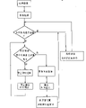
With reference to the process flow diagram of Fig. 3, will illustrate among the present invention and operate, stop, recovering servo-controlled method.
After electricity loaded to disk set or magnetic tape equipment, disk among the present invention or magnetic tape equipment in 0 cylinder or 0 magnetic track, made device itself be in the READY state MR head position.Whether if principal computer does not send processing command in a specified time interval, magnetic head is positioned 0 cylinder or 0 magnetic track with regard to unnecessary always, connect and carrying out an order so will judge principal computer.Perhaps, if principal computer does not connect and principal computer does not send bind command, then stop servocontrol and stop supplies current sensor to prevent 2 work of MR magnetic head.In the case, device waits for that principal computer sends bind command.
After device receives bind command from principal computer, just restart servocontrol, make its work, carry out RTZ action (making zero) to MR magnetic head group supply current sensor, MR magnetic head group is positioned 0 cylinder or 0 magnetic track, and carries out processing command from principal computer.In magnetic tape equipment, the RTZ action can be saved.In reference Fig. 3 illustration, illustrate as an example in the location of 0 cylinder or 0 magnetic track, but the RTZ action can be carried out in the optional position of disk 1 or tape 1 ' similarly.
Second kind of control method is as follows: the configuration as shown in Figure 1 disk set or in magnetic tape equipment shown in Figure 2, the positioning control of magnetic head is by carrying out with particular sample periodic sampling servosignal, and when disk set or magnetic tape equipment are in the no datat visit order from waiting status that principal computer sends, it is many until infinite that sampling period is extended to twice, makes to supply the time decreased of current sensor to below half to magneto-resistance effect element.
With reference to the process flow diagram of Fig. 4, with the method in explanation above-mentioned switch sampling cycle.
After electricity loaded to disk set or magnetic tape equipment, disk or the magnetic tape equipment of having used this control method were positioned MR magnetic head 2 for 0 cylinder or 0 magnetic track, make device self be in the READY state.In magnetic tape equipment, the RTZ action can be saved.
When principal computer does not send processing command in a specified time interval, magnetic head is with regard to unnecessary 0 cylinder or 0 magnetic track of being positioned accurately always, therefore, it is many until infinite that sampling period is extended to twice, thereby reducing to fewer than half until zero to the time of magneto-resistance effect element supply current sensor.In the case, disk set or magnetic tape equipment are waited for the bind command from principal computer.When the bind command that receives from principal computer, disk or magnetic tape equipment will return to particular value in the sampling period, and the time to magneto-resistance effect element supply current sensor is provided with back normal length, and with magnetic head with high-precision fixed 0 cylinder or 0 magnetic track of being positioned at.In the above description, provided the situation of a kind of head position, but magnetic head can be positioned the optional position of disk 1 or tape 1 ' in 0 cylinder or 0 magnetic track.
The third control method is as follows: in configuration disk set as shown in Figure 1, do not carry out servocontrol when empty the searching taken place, and the stop supplies current sensor is to prevent 2 work of MR magnetic head.
Usually, if principal computer does not send processing command and is longer than the set time, when disk set self is in the READY state, prevent that MR magnetic head long-time execution on specific cylinder from following action, magnetic head has just been carried out and has been sought action.In other words, disk set automatically performs a fixing searching action.At this moment, the feedback circuit of servo-control system is closed, and provides a little value that voice coil motor 4 is slowly rotated for power amplifier 13 by servo control circuit 12.
With reference to the process flow diagram of Fig. 5, the above-mentioned sky of explanation is searched the method that stops in the action and recover servo control operation.Disk set is positioned MR magnetic head 2 for 0 cylinder or arbitrary cylinder in the present embodiment, and follows action in execution and wait for processing command simultaneously.If a particular segment in the time principal computer do not send processing command, magnetic head has just been carried out and has been sought to improve wear problem.By discharging FEEDBACK CONTROL, stop to magneto-resistance effect element supply current sensor, and voice coil motor is applied fixed voltage with Fixed Time Interval, carry out the empty action of seeking.Also can be by detecting the electric current in the voice coil motor and estimating that the actual speed rate of voice coil motor motion controls speed.
If the voltage that adds of facility is Vc, and the back electromotive force constant of establishing coil is Kb, and then the maximum rate of Chan Shenging can be expressed as:
V=Vc/Kb
This empty search operation is by being undertaken by a kind of rate controlled of executing voltage Vc decision.This control method makes to search at sky carries out the while and can allow the MR magnetic head not work and stop to magneto-resistance effect element supply induction current.In the case, disk set is waited for the bind command from principal computer.When the bind command that receives from principal computer, disk set recovers servocontrol, to magneto-resistance effect element supply current sensor, carries out RTZ action, MR magnetic head group is positioned 0 cylinder, and carries out the processing command from principal computer.In the explanation that reference Fig. 5 is done, provided the situation of a kind of head position, but magnetic head can be searched action at the optional position of disk 1 execution sky in 0 cylinder.When using a kind of data surface servo-control system, by reading information such as track number, magnetic head can start immediately seeks action.
Use such scheme, on the basis of the affected estimation of function institute of considering the whole magnetic disk device, make that reducing conduction time from current sensor to magneto-resistance effect element that supply becomes possibility.
Effect of the present invention is as follows:
By the present invention, conduction time from current sensor to the magneto-resistance effect element of MR magnetic head that supply shortens greatly, therefore can prevent because the element characteristic that electronics drift etc. cause degenerates, and can prolong the life-span of MR magnetic head.According to the present invention, can produce the effect that to sacrifice reliability and increase the output of MR magnetic head group, thereby just may prolong the height output magnetic recording of use magneto-resistance effect element and the life-span of transcriber.
With reference to corresponding illustrate preferred forms of the present invention after, as can be known the present invention do not limit embodiment and as described in the accessory claim, a people who is skilled in technique can produce multiple change or modification, and does not deviate from spirit of the present invention and intention.

Claims (8)

1. method of controlling magnetic recording and transcriber, this magnetic recording and transcriber have a magnetic head that adopts magneto-resistive effect element, a carriage and the control circuit that is used to locate described carriage that described magnetic head is installed, and said method comprising the steps of:
When generation does not have visit order from waiting status that principal computer sends, stop to be used for the work of the feedback control system that magnetic head positioned according to the servo-information that reads from magnetic head; And
Irrespectively the mobile or location of magnetic head is controlled with the servo-information that magnetic head reads, made magnetic head not to be positioned on the particular lane constantly.
2. according to the control magnetic recording of claim 1 and the method for transcriber, it is characterized in that described controlled step carries out by fixed intervals.
3. according to the control magnetic recording of claim 1 and the method for transcriber, it is characterized in that after the work that has stopped feedback control system, irrespectively mobile the or location of magnetic head is controlled with the servo-information that magnetic head reads.
4. according to the control magnetic recording of claim 3 and the method for transcriber, it is characterized in that described magnetic recording and transcriber are disk sets, magnetic head moved or locate the control carried out produce, and wherein the speed of magnetic head is to utilize to impose the back electromotive force that is directly proportional with the voice coil motor translational speed that fixed voltage produces with fixed intervals to voice coil motor and controlled by voice coil motor.
5. according to the control magnetic recording of claim 3 and the method for transcriber, it is characterized in that described magnetic recording and transcriber are disk sets, magnetic head moved or locate the control carried out produce, and wherein the speed of magnetic head is by detecting the electric current in the voice coil motor and estimating that the actual translational speed of voice coil motor is controlled by voice coil motor.
6. magnetic recording and playback system comprise:
A magnetic head that adopts magnetoresistive element;
One in the face of described magnetic head and the magnetic medium that supported by the relation that relatively moves with described magnetic head;
A feedback control system comprises:
A recording is used for amplifying passing to electric signal described magnetic head and that spread out of from described magnetic head by electromagnetic conversion;
Reproduce to select circuit for one, be used to select to be positioned on the described magnetic medium corresponding to the position of described magnetic head and signal that send from described magnetic head;
A servosignal reproducing circuit is used for selecting circuit received signal and reproduction to be used for the signal of control head position from described reproduction;
A servo control circuit is used for controlling from described servosignal reproducing circuit received signal and to the position of magnetic head on magnetic medium; And
A power amplifier is used for from the servo control circuit received signal and amplifies;
An electric machine is used for from the power amplifier received signal and is mechanical force with this conversion of signals;
A carriage, it moves by described power amplifier control, is used to support described magnetic head; And
Interface and control circuit have the function to mailing to and controlling and stop the work of described feedback control system from the input and output of order, data and other signals of principal computer;
Wherein said servo control circuit has a kind of like this function: when generation does not have visit order from waiting status that principal computer sends, after feedback control system fails, provide signal to described power amplifier, make described magnetic head carry out seek action, and the servo-information that reads with magnetic head is irrelevant.
7. according to the magnetic recording and the playback system of claim 6, it is a kind of after feedback control system fails to it is characterized in that described servo control circuit has, and provides a kind of signal the feasible function that applies fixed voltage with fixed intervals to described motor to described power amplifier.
8. according to the magnetic recording and the playback system of claim 6, it is a kind of after feedback control system fails to it is characterized in that described servo control circuit has, detect described electric machine electric current, estimate the actual translational speed of described electric machine and provide signal so that control the function of the translational speed of described magnetic head to described power amplifier.
CN95103514A 1994-03-18 1995-03-17 Magnetic recording/reproducing apparatus and control method thereof Expired - Lifetime CN1069771C (en)

Applications Claiming Priority (3)

Application Number Priority Date Filing Date Title
JP048350/94 1994-03-18
JP06048350A JP3134657B2 (en) 1994-03-18 1994-03-18 Magnetic disk drive
JP048350/1994 1994-03-18

Publications (2)

Publication Number Publication Date
CN1115069A CN1115069A (en) 1996-01-17
CN1069771C true CN1069771C (en) 2001-08-15

Family

ID=12800933

Family Applications (1)

Application Number Title Priority Date Filing Date
CN95103514A Expired - Lifetime CN1069771C (en) 1994-03-18 1995-03-17 Magnetic recording/reproducing apparatus and control method thereof

Country Status (6)

Country Link
US (1) US5606470A (en)
EP (2) EP0978824B1 (en)
JP (1) JP3134657B2 (en)
CN (1) CN1069771C (en)
DE (2) DE69517224T2 (en)
PH (1) PH31527A (en)

Families Citing this family (13)

* Cited by examiner, † Cited by third party
Publication number Priority date Publication date Assignee Title
US5793550A (en) * 1996-04-23 1998-08-11 Read-Rite Corporation Magnetoresistive head using sense currents of opposite polarities
JP3117658B2 (en) * 1997-03-19 2000-12-18 富士通株式会社 Magnetic reproducing device equipped with MR head
US6385000B1 (en) * 1998-08-21 2002-05-07 International Business Machines Corporation System and method for extending the operating life of a magnetoresistive transducer provided in a disk drive system
US6455280B1 (en) 1998-12-22 2002-09-24 Genset S.A. Methods and compositions for inhibiting neoplastic cell growth
US6574061B1 (en) 1999-08-27 2003-06-03 Seagate Technology Llc Method and apparatus for run-time temperature compensation of giant magnetoresistive head bias current
JP2001067765A (en) 1999-08-31 2001-03-16 Hitachi Ltd Magnetic disk device, and its control method
JP4337317B2 (en) * 2002-09-06 2009-09-30 ソニー株式会社 Information processing apparatus and program
JP2005157622A (en) * 2003-11-25 2005-06-16 Hitachi Ltd Disk array device for idle seek
JP2005346816A (en) * 2004-06-02 2005-12-15 Hitachi Global Storage Technologies Netherlands Bv Data storage device and its control method
JP2008243293A (en) 2007-03-27 2008-10-09 Toshiba Corp Recording and reproducing device with probe memory
US7963023B2 (en) * 2007-11-16 2011-06-21 Oracle America, Inc. Process for accurately machining a magnetic tape head
US11386921B2 (en) 2020-09-30 2022-07-12 Seagate Technology Llc Read head stress reduction
US11341989B2 (en) * 2020-09-30 2022-05-24 Seagate Technology Llc Read head stress reduction

Citations (1)

* Cited by examiner, † Cited by third party
Publication number Priority date Publication date Assignee Title
EP0361786A2 (en) * 1988-09-26 1990-04-04 International Business Machines Corporation Disk file digita servo control

Family Cites Families (7)

* Cited by examiner, † Cited by third party
Publication number Priority date Publication date Assignee Title
US4589036A (en) * 1984-12-03 1986-05-13 International Business Machines Corporation Apparatus and method for instrumented radial translation of a read/write transducer at start-up of a rotating disk file
JPH02131348A (en) * 1988-11-08 1990-05-21 Fujitsu Ltd Voice coil motor for optical disc device
US5345347A (en) * 1992-02-18 1994-09-06 Western Digital Corporation Disk drive with reduced power modes
JPH05226850A (en) 1992-02-18 1993-09-03 Fujitsu Ltd Binding for portable apparatus
US5408369A (en) * 1992-04-23 1995-04-18 Teac Corporation Power saving system for rotating disk data storage apparatus
JP2671780B2 (en) * 1993-01-07 1997-10-29 日本電気株式会社 Servo device for recording / reproducing separated type magnetic disk device, and actuator force constant estimating method and compensating method in disk device
US5381279A (en) * 1993-10-13 1995-01-10 Maxtor Corporation Disk drive system with adjustable spindle and actuator power to improve seek and access performance

Patent Citations (1)

* Cited by examiner, † Cited by third party
Publication number Priority date Publication date Assignee Title
EP0361786A2 (en) * 1988-09-26 1990-04-04 International Business Machines Corporation Disk file digita servo control

Also Published As

Publication number Publication date
EP0673032B1 (en) 2000-05-31
JP3134657B2 (en) 2001-02-13
DE69517224T2 (en) 2001-02-22
EP0673032A3 (en) 1997-11-05
DE69517224D1 (en) 2000-07-06
PH31527A (en) 1998-11-03
DE69533207D1 (en) 2004-07-29
EP0673032A2 (en) 1995-09-20
CN1115069A (en) 1996-01-17
EP0978824B1 (en) 2004-06-23
JPH07262539A (en) 1995-10-13
EP0978824A2 (en) 2000-02-09
EP0978824A3 (en) 2000-03-29
US5606470A (en) 1997-02-25
DE69533207T2 (en) 2005-06-30

Similar Documents

Publication Publication Date Title
CN1069771C (en) Magnetic recording/reproducing apparatus and control method thereof
EP1775721A2 (en) Method of writing a reference servo signal of hard disk drive and apparatus suitable therefor
TWI480866B (en) Servo system and operating method thereof
KR100255207B1 (en) Unlatching control method for hdd
KR0182951B1 (en) Method and device for auto-writing of servo data for a hard disk drive
KR100532481B1 (en) Apparatus and method for unlatching of hard disk drive
CN1272767C (en) Method for compensating data recording beginning time and magnetic diskusing the same
CN1174377C (en) Information storage apparatus
CN1300797C (en) Apparatus and method for controlling head unload operation in disk drive
US6967807B2 (en) Selecting physical cylinders in a disc drive employing discs with pre-written servo patterns
US5461521A (en) Magnetic disk unit control method for removing dust from a disk
KR920018713A (en) Data recorder
CN85108798A (en) Head position control system in the disk set of transposable servo system
US4592035A (en) Information signal track search system in a rotary recording medium reproducing apparatus
CN1920993A (en) Data storage device and a method of controlling write of user data thereof
US6271636B1 (en) Servo control system and method for a data storage device with improved braking
US5854715A (en) Method for tracking a read head on a data area on a disk and disk apparatus using the method
CN1428766A (en) Method and equipment for mounting magnetic head to magnetic disk medium from magnetic disk drive slope piece
JP2953191B2 (en) Magnetic disk drive
KR100640607B1 (en) Method for controlling restoration from alarm state to normal state and disk drive using the same
US6304404B1 (en) Recording medium driving apparatus and tracking method
JPH09161250A (en) Information recording medium, information recording and reproducing method thereof
KR20110090167A (en) Method for controlling track seeking servo in hard disk drive and hard disk drive controlled by the same
JPH02282973A (en) Optical information recording and reproducing device
KR900006185B1 (en) Apparatus for track division of magnetic disc in fdd

Legal Events

Date Code Title Description
C10 Entry into substantive examination
SE01 Entry into force of request for substantive examination
C10 Entry into substantive examination
SE01 Entry into force of request for substantive examination
C06 Publication
PB01 Publication
C14 Grant of patent or utility model
GR01 Patent grant
ASS Succession or assignment of patent right

Owner name: HITACHI GLOBAL STORAGE TECHNOLOGIES JAPAN LTD.

Free format text: FORMER OWNER: HITACHI CO., LTD.

Effective date: 20031230

C41 Transfer of patent application or patent right or utility model
TR01 Transfer of patent right

Effective date of registration: 20031230

Address after: Kanagawa, Japan

Patentee after: Hitachi Global Scinece Technology Jappan Co., Ltd.

Address before: Tokyo, Japan

Patentee before: Hitachi Ltd.

C17 Cessation of patent right
CX01 Expiry of patent term

Expiration termination date: 20150317

Granted publication date: 20010815