CN106970886B - Controlling a physical link of a first protocol using an extended functionality architecture of a second protocol - Google Patents
Controlling a physical link of a first protocol using an extended functionality architecture of a second protocol Download PDFInfo
- Publication number
- CN106970886B CN106970886B CN201610875887.8A CN201610875887A CN106970886B CN 106970886 B CN106970886 B CN 106970886B CN 201610875887 A CN201610875887 A CN 201610875887A CN 106970886 B CN106970886 B CN 106970886B
- Authority
- CN
- China
- Prior art keywords
- link
- physical
- pcie
- layer
- protocol
- Prior art date
- Legal status (The legal status is an assumption and is not a legal conclusion. Google has not performed a legal analysis and makes no representation as to the accuracy of the status listed.)
- Active
Links
Images


Classifications
-
- G—PHYSICS
- G06—COMPUTING; CALCULATING OR COUNTING
- G06F—ELECTRIC DIGITAL DATA PROCESSING
- G06F13/00—Interconnection of, or transfer of information or other signals between, memories, input/output devices or central processing units
- G06F13/38—Information transfer, e.g. on bus
- G06F13/40—Bus structure
- G06F13/4004—Coupling between buses
- G06F13/4027—Coupling between buses using bus bridges
-
- G—PHYSICS
- G06—COMPUTING; CALCULATING OR COUNTING
- G06F—ELECTRIC DIGITAL DATA PROCESSING
- G06F13/00—Interconnection of, or transfer of information or other signals between, memories, input/output devices or central processing units
- G06F13/38—Information transfer, e.g. on bus
- G06F13/382—Information transfer, e.g. on bus using universal interface adapter
- G06F13/385—Information transfer, e.g. on bus using universal interface adapter for adaptation of a particular data processing system to different peripheral devices
-
- G—PHYSICS
- G06—COMPUTING; CALCULATING OR COUNTING
- G06F—ELECTRIC DIGITAL DATA PROCESSING
- G06F13/00—Interconnection of, or transfer of information or other signals between, memories, input/output devices or central processing units
- G06F13/38—Information transfer, e.g. on bus
- G06F13/42—Bus transfer protocol, e.g. handshake; Synchronisation
- G06F13/4265—Bus transfer protocol, e.g. handshake; Synchronisation on a point to point bus
-
- Y—GENERAL TAGGING OF NEW TECHNOLOGICAL DEVELOPMENTS; GENERAL TAGGING OF CROSS-SECTIONAL TECHNOLOGIES SPANNING OVER SEVERAL SECTIONS OF THE IPC; TECHNICAL SUBJECTS COVERED BY FORMER USPC CROSS-REFERENCE ART COLLECTIONS [XRACs] AND DIGESTS
- Y02—TECHNOLOGIES OR APPLICATIONS FOR MITIGATION OR ADAPTATION AGAINST CLIMATE CHANGE
- Y02D—CLIMATE CHANGE MITIGATION TECHNOLOGIES IN INFORMATION AND COMMUNICATION TECHNOLOGIES [ICT], I.E. INFORMATION AND COMMUNICATION TECHNOLOGIES AIMING AT THE REDUCTION OF THEIR OWN ENERGY USE
- Y02D10/00—Energy efficient computing, e.g. low power processors, power management or thermal management
Abstract
In one embodiment, a method comprises: accessing a first field of a first link function register of a first device having a protocol stack including a transaction layer and a link layer according to a first communication protocol, and a physical layer of the protocol stack having a physical unit of a second communication protocol; using the first field as a pointer value to a location in a second link function register of the first device, and using information from the location in the second link function register to perform a configuration operation for a physical link coupled to the device. Other embodiments are described and claimed.
Description
The application is a divisional application, the original application of which is a patent application filed to the chinese patent office on 27/11/2014 (19/6/2013 as international application date), the application number is 201380027892.8, and the invention is named as "using an extended function structure of a second protocol to control a physical link of a first protocol".
Technical Field
Embodiments relate to interconnect technology.
Background
To provide communication between different devices within a system, some type of interconnection mechanism is used. A wide variety of such interconnections are possible depending on the system implementation. Typically, to enable two devices to communicate with each other, they share a common communication protocol.
One typical communication protocol for communicating between devices in a computer system is based on the PCI express-based protocolTMSpecification base Specification version 3.0 (published on 11/18/2010) (hereinafter PCIe)TMCanonical) link for fast peripheral component interconnectTM(PCI express)TM(PCIeTM) ) a communication protocol. The communication protocol is one of a load/store input/output (IO) interconnect systemAn example. Communication between devices is typically performed serially at very high speeds according to the protocol. The development of various parameters for the protocol is intended to achieve maximum performance regardless of power efficiency, as is PCIeTMCommunication protocols were developed for desktop computers. As a result, many of its features have not been scaled down to lower power solutions that can be incorporated into mobile systems.
In addition to these power issues with conventional load/store communication protocols, existing link management schemes are typically very complex and involve many states, making long processes to perform transitions between states. This is due in part to existing link management mechanisms that were developed to include a variety of different form factor requirements, e.g., connectors, consolidation of different systems, etc. One such example is in accordance with PCIeTMLink management for communication protocols.
Drawings
Fig. 1 is a high-level block diagram of a protocol stack of a communication protocol according to an embodiment of the present invention.
FIG. 2 is a block diagram of a system on chip (SoC) according to an embodiment of the present invention.
Fig. 3 is a block diagram of a physical unit according to another embodiment of the present invention.
Fig. 4 is a block diagram illustrating further details of a protocol stack according to an embodiment of the invention.
Fig. 5 is a state diagram of a link training state machine that may be part of a link manager according to an embodiment of the present invention.
FIG. 6 is a flow diagram of various states of a sideband mechanism according to an embodiment of the invention.
FIG. 7 is a flow diagram of a method according to an embodiment of the invention.
FIG. 8 is a block diagram of components present in a computer system, according to an embodiment of the invention.
FIG. 9 is a block diagram of an example system that can be used with embodiments.
Fig. 10 is a timing diagram illustrating a reconfiguration request according to one embodiment of the invention.
Fig. 11 is a timing diagram illustration of a reconfiguration request according to another embodiment of the present invention.
FIG. 12 is a block diagram of a recovery sub-state machine according to one embodiment of the invention.
Fig. 13 is a block diagram of a functional structure according to an embodiment of the present invention.
Fig. 14 is a flow chart of a method according to another embodiment of the invention.
Detailed Description
Embodiments may provide a system having a low power, load/store architecture and particularly suitable for use in mobile devices (including cellular phones, e.g., smart phones, tablet computers, e-readers, ultrabooks, etc.)TMEtc.) are used in the same manner as described above.
In various embodiments, a protocol stack for a given communication protocol may be used with physical units of a different communication protocol or at least with Physical (PHY) units that are different from the physical units for the given communication protocol. The physical unit includes both a logic layer and a physical or electrical layer that provides actual, physical communication of information signals through an interconnect (e.g., a link that links two separate semiconductor dies), which may be two semiconductor dies within a single Integrated Circuit (IC) package or separate packages coupled, for example, via circuit board routing, traces, etc. In addition, the physical unit may perform framing/unframing of data packets, perform link training and initialization, and process transmitting or receiving data packets to or from the physical interconnect.
Although various implementations are possible, in one embodiment, the protocol stack may have a conventional Personal Computer (PC) -based communication protocol (e.g., according to PCI express)TMSpecification base Specification version 3.0 (published on 11/18/2010) (hereinafter PCIe)TMSpecification) fast peripheral component interconnectTM(PCI)(PCIeTM) Communication protocol), a further version of an application protocol extension or another such protocol, however, the physical unit is not in accordance with PCIeTMA communication protocol. This physical unit may be specially designed for the following purposes: enabling low power operation for enabling substantially invariant PCIeTMA merging of an upper layer protocol stack with the low power physical circuit. In this way, PCIe may be utilizedTMA widely existing foundation for communication protocols to be incorporated into portable and other non-PC based form factors that operate at low power. Although the scope of the present invention is not limited in this respect, in one embodiment, the physical element may be a physical element adapted from a mobile platform, such as a so-called M-PHY according to M-PHY specification version 1.00.00(2011, 2/8) (MIPI director approved by 2011, 4/28) (hereinafter MIPI specification) of the Mobile Industry Processor Interface (MIPI) alliance, which is a group that establishes standards for mobile computer devices. However, other low power physical units (e.g., according to other low power specifications (e.g., for coupling separate dies together within a multi-chip package)) or customized low power solutions may be used. As used herein, the term "low power" refers to a level of power consumption that is lower than conventional PC systems and which may be suitable for use in a variety of mobile and portable devices. By way of example, "low power" may be more conventional PCIe thanTMThe physical unit consumes less power.
Thus, by having a traditional PCIe with different types of physical unitsTMProtocol stack aggregation, available for PCIeTMSubstantial reuse of existing components developed for incorporation into mobile or other portable or low power platforms.
Embodiments may also utilize the following recognition: existing load/store IO technology, in particular PCIeTMIt is designed to achieve maximum performance where efficacy is not a major issue and thus is not scaled to low power applications. By combining portions of a conventional load/store protocol stack with physical units of low power design, embodiments may preserve PCIeTMWhile achieving the best level of power at the device and platform level.
Also, embodiments may be of greater sizeBasic Universal PCIeTMArchitecture compatible software. In addition, embodiments can also enable direct PHY reuse for mobile design PHYs (e.g., M-PHYs). As such, when the PH can operate at a clock rate that does not interfere with the associated radio, (since harmonics of the clock frequency of the PHY do not interfere with common radio frequencies at which typical radio solutions operate (e.g., 1.8, 1.9, 2.4 gigahertz (GHz), or other such radio frequencies)), both low active and idle power can be achieved with efficient power/bits transferred along with a method that is a friendly electromagnetic/radio frequency interface (EMI/RFI).
Embodiments may further provide architectural enhancements that enable optimized link training and management mechanisms (LTSSM); optimized flow control and retry buffering and management mechanisms; an architectural protocol for changing the mode of operation of the link; fast hardware-supported device state saving and recovery; and an integrated sideband mechanism for link management with optional in-band support.
In various embodiments, PCIeTMThe transaction and data link layers may be implemented as part of a protocol stack with limited modifications to account for different link speeds and asymmetric links. In addition, improved link training and management may be provided for support including multi-way communication, asymmetric link configuration, sideband consolidation, and dynamic bandwidth scalability. Embodiments may further provide for the use of existing PCIe-based PCIeTMOr not based on PCIeTMAnd (3) bridging between logic and circuitry (e.g., M-PHY logic and circuitry).
The layered approach enables existing software stacks (e.g., Operating System (OS), virtual machine manager, and drivers) to run seamlessly across different physical layers. The impact on the data link and transaction layers is minimized and may include updates to timers related to update acknowledgment frequency, replay timers, etc.
Thus, embodiments may limit PCIeTMSome flexibility is provided in the system, as the flexibility may be in PCIe in some casesTMCertain complexity arises in both systems and other systems. This is why these protocols simultaneously provide a lot of flexibility to implement plug and play functionality. Rather, embodiments may tailor solutions that minimize the amount of flexibility in design, as known and fixed configurations occur when incorporated into a given system (e.g., a system on a chip (SoC)), interconnected to another integrated circuit. Because of the implementation of the exact configuration presented, when both the SoC and connected devices are attached within the platform (e.g., soldered to a circuit board of the system), no plug-and-play functionality with respect to these devices is required, and thus, PCIe may not be requiredTMOr other PC-based communication protocols, which enables seamless incorporation of different devices into a system with plug-and-play functionality.
As one example, an SoC may serve as a root complex implemented in a first IC and coupled to a second IC, which may be a radio solution, which may include one or more devices of a plurality of wireless communication devices. Such devices may range from low power short range communication systems (e.g., according to bluetooth)TMSpecification), local wireless communications (e.g., so-called WiFi according to a given Institute of Electrical and Electronics Engineers (IEEE)802.11 standardTMSystem) to higher power wireless systems (e.g., given cellular communication protocols (e.g., 3G or 4G communication protocols)).
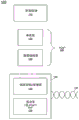
Referring now to fig. 1, fig. 1 depicts a high-level block diagram of a protocol stack of a communication protocol in accordance with an embodiment of the present invention. As shown in fig. 1, the stack 100 may be a combination of software, firmware, and hardware within a semiconductor component (e.g., an IC) for providing processing of data communications between a semiconductor device and another device coupled to the semiconductor device. In the embodiment of FIG. 1, which shows a high-level view starting with higher-level software 110, the software 110 may be various types of software executing on a given platform. The higher level software may include Operating System (OS) software, firmware, application software, and the like. Data transmitted via interconnect 140, which interconnect 140 may be a semiconductor device and another device, may pass through the layers of a protocol stack, shown generally in FIG. 1Given physical interconnections to which the components are coupled. As shown, the portion of the protocol stack may be conventional PCIeTMPortions of the stack 120 and may include a transaction layer 125 and a data link layer 128. In general, the transaction layer 125 functions to generate transaction layer data packets (TLPs), which may be request or response based packets separated by time, to allow the link to carry other traffic as the target device collects data for the response. The transaction layer further handles credit-based flow control. Thus, the transaction layer 125 provides an interface between the processing circuitry and the interconnect architecture (e.g., data link layer and physical layer) of the device. In this regard, the primary responsibility of the transaction layer is in the assembly and disassembly of packets (i.e., Transaction Layer Packets (TLPs)) and in the handling of credit-based flow control.
In turn, the data link layer 128 may order TLPs generated by the transaction layer and ensure reliable delivery (including processing error checking) and acknowledgment processing of TLPs between two endpoints. Thus, the link layer 128 serves as an intermediate stage between the transaction layer and the physical layer, and provides a reliable mechanism for exchanging TLPs between the two components over the link. One side of the link layer receives a TLP assembled by the transaction layer and the application identifier; calculating and applying an error detection code (e.g., a Cyclic Recovery Code (CRC)); and submitting the modified TLP to the physical layer for transmission across the physical link to the external device.
After processing in the data link layer 128, the packet may be transmitted to the PHY unit 130. In general, PHY unit 130 may include a low power PHY134, and low power PHY134 may include a logical layer and a physical (including electronic) sublayer. In one embodiment, the physical layer represented by the PHY unit 130 physically transmits the packet to an external device. The physical layer includes: a transmit section for preparing outgoing information for transmission and a receiver section for identifying and preparing received information before passing it to the link layer. The transmitter is assembled with symbols that are serialized and transmitted to an external device. The receiver is populated with serialized symbols from an external device and it converts the received signal into a bit stream. The bitstream is deserialized and provided to a logical sub-block.
In one embodiment, low power PHY134 may provide processing of packetized data for communication along interconnect 140, and low power PHY134 may be a given low power PHY specially developed or adapted from another PHY (e.g., an M-PHY). As further seen in fig. 1, a link training and management layer 132 (also referred to herein as a link manager) may also be present within the PHY unit 130. In various embodiments, the link manager 132 may include: may be in accordance with another communication protocol (e.g., PCIe)TMProtocol) and for processing data in a conventional protocol stack (e.g., PCIe above)TMProtocol stack) and physical PHY134 of a different protocol.
In the embodiment of fig. 1, interconnect 140 may be implemented as a differential pair of wires, which may be two pairs of unidirectional wires. In some embodiments, multiple sets of differential pairs may be used to increase bandwidth. Note that according to PCIeTMThe number of differential pairs in each direction must be the same for the communication protocol. However, according to various embodiments, a different number of pairs may be provided in each direction, which allows for more efficient and lower power operation. The integrally aggregated stack and link 140 may be referred to as mobile express PCIeTMAn interconnect or a link. While the embodiment of fig. 1 is shown at this high level, it is to be understood that the scope of the present invention is not so limited. That is, it is to be understood that the diagram shown in fig. 1 is merely with respect to a protocol stack and higher level software from the transaction layer through the physical layer, and that various other circuits of the SoC or other semiconductor devices including the stack are not shown.
Referring now to fig. 2, fig. 2 illustrates a block diagram of a SoC, in accordance with an embodiment of the present invention. As shown in fig. 2, SoC 200 may be any type of SoC for implementation into various types of platforms, ranging from relatively small, low-power portable devices (e.g., smart phones, personal digital assistants (PADs), tablets, netbooks, ultrabooks, etc.)TMEtc.) to more advanced socs that can be implemented in higher level systems.
As in fig. 2Illustratively, SoC 200 may include one or more cores 2100-210n. Thus, in various embodiments, a multi-core SoC is possible in which all cores may be homogeneous cores of a given architecture (e.g., an in-order or out-of-order processor). Alternatively, heterogeneous cores may be present, e.g., some relatively small low-power cores of an in-order architecture, with additional cores being present in architectures that may be larger and more complex (e.g., out-of-order architectures). The protocol stack enables communication of data between one or more of the cores and other components of the system. As seen, the stack may include software 215, which may be higher level software (e.g., OS), firmware, and application level software executing on one or more cores. In addition, the protocol stack includes a transaction layer 220 and a data link layer 230. In various embodiments, these transaction and data link layers may have a given communication protocol, e.g., PCIeTMAnd (4) protocol. Of course, layers of different protocol stacks (e.g., according to the Universal Serial Bus (USB) protocol stack) may be present in other embodiments. Also, in some embodiments, a low power PHY circuit as described herein may be multiplexed with an existing standby protocol stack.
Still referring to fig. 2, the protocol stack may in turn be coupled to a physical unit 240, which physical unit 240 may comprise a plurality of physical units that may provide communication via a plurality of interconnects. In one embodiment, first physical unit 250 may be a low power PHY unit, which may correspond to an M-PHY according to the MIPI specification in one embodiment, for providing communication via host interconnect 280. In addition, a Sideband (SB) PHY unit 244 may be present. In the illustrated embodiment, the sideband PHY units may provide communication via a sideband interconnect 270, which sideband interconnect 270 may be an integrated sideband for providing certain sideband information, e.g., at a lower data rate than a main interconnect 280 coupled to the first PHY 250. In some embodiments, various layers of a protocol stack may have a separate sideband coupled to the SB PHY 244 to enable communication along the sideband interconnect.
Additionally, PHY unit 240 may further include an SB link manager 242, which may be used to control SB PHY 244. Additionally, a link training and status manager 245 may be present and may be used to adapt a protocol stack having a first communication protocol to a first PHY250 having a second communication protocol and provide overall control of the first PHY250 and interconnect 280.
As can be further seen, various components may be present in the first PHY 250. More specifically, transmitter and receiver circuitry (i.e., TX 253 and RX 254) may be present. In general, the circuitry may be used to perform serialization operations, deserialization operations, along with the transmission and reception of data via the main interconnect 280. The save state manager 251 may be present and when the first PHY250 is in a low power state, the save state manager 251 may be used to save configuration and other state information about the first PHY 250. Likewise, encoder 252 may be present for performing line encoding, for example, according to the 8b/10b protocol.
As further seen in fig. 2, a mechanical interface 258 may be present. The mechanical interface 258 may be a given interconnect for providing communication from the root complex 200 and, more particularly, for providing communication from/to the first PHY250 via the primary interconnect 280. In various embodiments, the mechanical connections may be plated as pins (e.g., Ball Grid Array (BGA)) or other surface mount for the semiconductor device, or through-hole connections.
In addition to these primary communication mechanisms, the additional communication interface may also function as a Low Power Serial (LPS) PHY unit 255 coupled via a separate stack that includes: a software layer 216, a transaction layer 221, and a link layer 231 between the core 210 and one or more off-chip devices 260a-c, which may be various low data rate peripherals such as sensors, accelerometers, temperature sensors, Global Positioning System (GPS) circuitry, compass circuitry, touch screen circuitry, keyboard circuitry, mouse circuitry, and the like.
It is noted that in various embodiments, both sideband interconnect 270 and main interconnect 280 may be coupled between SoC 200 and another semiconductor component (e.g., another IC, such as a multi-sideband radio solution).
Also when the illustration of fig. 2 is at a relatively high level, variations are possible. For example, multiple low power PHYs may be provided for achieving higher data communication rates, e.g., via multiple channels, where each channel is associated with a separate PHY. Referring now to fig. 3, fig. 3 shows a block diagram of a physical unit in accordance with another embodiment of the present invention. As shown in fig. 3, the physical unit 300 includes a link training and status manager 310. The state manager may be as described above and may be a collection of logic to interface a protocol stack implementing a first communication protocol with a physical unit of a second communication protocol (e.g., a different communication protocol).
As further seen in FIG. 3, link training and status manager 310 may be associated with a plurality of M-PHYs 3200-320nAnd (4) communication. By providing more than one such PHY, higher data communication rates may occur. It is noted that while each of the M-PHYs shown in fig. 3 may include a certain amount of logic for causing separate, independent communications of the M-PHYs to occur, overall control of the communications of these different M-PHYs may be via the link training and status manager 310. It is also to be understood that while fig. 3 shows multiple M-PHYs, in other embodiments, multiple PHY units of another type may be present, and further multiple heterogeneous PHY units may be provided. It is noted that each M-PHY unit may be used as part of a unique logical link or in groups, where the groups are associated with a single logical link. Each device may typically use a single logical link, however in some embodiments a single physical device may use multiple logical links, e.g., dedicated link resources for providing different functions of a multi-function component.
Referring now to fig. 4, fig. 4 illustrates a block diagram showing further details of a protocol stack, according to an embodiment of the invention. As shown in fig. 4, stack 400 includes various layers including a transaction layer 410, a data link layer 420, and a physical layer 430. As described above, these different layers may use PCIeTMConventional transaction and data link portions of a protocol stack orOne of such modified versions of the stack is configured to accommodate interaction between these layers of the first communication protocol and a physical layer of another communication protocol (which, in the embodiment of fig. 4, may be an M-PHY according to the MIPI specification).
As shown in fig. 4 with respect to the transmission direction in which information is transmitted from the protocol stack 400, incoming information to the protocol stack (e.g., from other circuitry of the SoC (e.g., a core or other processing logic)) is received in a transport packet assembler 412 at the transaction layer, which transport packet assembler 412 typically incorporates control and data pathways for forming a TLP. After being assembled into a transport packet, which in various embodiments may be a data packet having, for example, 1 to 4096 bytes (or less maximum allowed size, e.g., 128 or 256), the assembled packet is provided to flow controller 414, which flow controller 414 determines whether sufficient flow control credits are available and controls the injection of the packet into data link layer 420 based on the number of next TLPs required for queuing for transmission. As can be seen more particularly, these injected packets are provided with an error checker and sequencer 422, which sequencer 422 may generate a TLP sequence number and LCRC in one embodiment. As further seen, data link layer 420 further includes a transport message mechanism 426, which transport message mechanism 426 in turn generates a DLLP for link management functions and which transport message mechanism 426 is coupled to a data link transmission controller 425, which data transmission controller 425 is a controller function for flow control and data link integrity (ACK/NAK) mechanisms; it is noted that it may be subdivided such that unique logic blocks may be used to implement these functions.
As further seen, the processed data packets are provided to a retry buffer 424, which retry buffer 424 holds a copy of each TLP until acknowledged by a component on the other side of the link, noting that in practice this may be achieved with buffering the stack higher up (in or above assembler 412), and storing them in the corresponding entities until they are selected for transmission to physical layer 430 via data/message selector 428. Usually, in order toThe transaction and data link layers described above may be in accordance with conventional PCIeTMThe protocol stack circuitry operates, with certain modifications described further below.
Rather, with respect to physical layer 430, many more modifications of certain logical components of that layer (e.g., in accordance with PCIe)TMModification of the protocol stack) may occur and be used to provide interfacing to the actual physical part of the physical unit of another communication protocol. As can be seen, incoming packets may be applied to a frame generator 432, which frame generator 432 adds physical layer frame symbols and generates frames of packets and provides them to a width/position mapper 434, which width/position mapper 434 shifts bytes in the data path for generating queues needed for external transmission, adjusts the data path width if needed, and is then coupled to a trainer and hop sequencer 436, which trainer and hop sequencer 436 may be used to perform link training and hop sequences. As can be seen, the frame generator 432, trainer/sequencer 436, and data/sequence selector 438 may all be coupled to a physical layer transmission controller 435, the physical layer transmission controller 435 being a transceiver portion of the LTSSM and associated logic. Block 436 is logic for generating physical layer transmissions (e.g., a Training Set (TS) and a hop ordered set). In this way, framed packets may be selected and provided to physical circuitry for performing encoding, sequencing, and driving onto the physical interconnect of the serialized signals corresponding to the processed packets. In one embodiment, the mapping of symbol differences between different communication protocols may be performed in the frame generator 432.
As can be seen, a plurality of individual channels or lines may be provided for the physical interconnect. In the illustrated embodiment, each physical channel or line may include its own independent PHY unit transmission circuitry 4450-445jIn one embodiment, the separate PHY unit transmission circuit 4450-445jEach of which may be part of an M-PHY unit according to the MIPI specification. As described herein, unlike PCIeTM(in PCIe)TMWhere the number of transmitters and receivers match),a different number of transmitters and receivers may be present. Thus, as can be seen, each transmission circuit 445 may include: an encoder that takes action to encode the symbols according to 8b/10b encoding; a sequencer for serializing the encoded symbols; and a driver for driving the signal onto the physical interconnect. As further seen, each line or channel may be associated with a logic unit 4400-440jIn association, the logic unit 4400-440jMay be logic circuitry for an M-PHY according to the MIPI specification, thereby serving to manage physical communications via the corresponding lines.
It is noted that the plurality of lines may be configured to operate at different rates, and embodiments may include different numbers of such lines. Furthermore, there may be different numbers of lines and line speeds in the transmission and reception directions. Thus, while a given logic unit 440 controls the operation of the corresponding lines of PHY445, it is understood that physical layer transmission controller 435 may act to control the overall transmission of information over the physical interconnect. It is noted that in some cases, some very basic function is performed by unique logic associated with each line; where a line may be allocated to more than a single link, multiple instances of LTSSM may be provided; for a trained link, there is a single LTSSM control transceiver and receiver side in each component. The overall control may include power control, link speed control, link width control, initialization, and the like.
Still referring to FIG. 4, incoming information received via the physical interconnect may similarly pass through the physical layer 430, the data link layer 420, and the transaction layer 410 via the receive mechanisms of the physical layer 430, the data link layer 420, and the transaction layer 410. In the embodiment shown in fig. 4, each PHY unit may further include a receive circuit, i.e., receive circuit 4550-455kIn the illustrated embodiment, the receive circuitry may be present for each line of the physical link. It is noted that in this embodiment, the number of receiver circuits 455 and transmitter circuits 445 is different. As can be seen, the physical circuitry may include an input buffer for receiving incoming information; a deserializer for deserializing the information; and a decoder that may take action to decode symbols transmitted in 8b/10b encoding. As further seen, each line or channel may be associated with a logic unit 4500-450kIn association, the logic unit 4500-450kMay be a logic circuit according to a given specification (e.g., the MIPI specification for M-PHY) to thereby manage physical communications via the corresponding line.
The decoded symbols may then be provided to the logical part of the physical layer 430, which, as can be seen, may include an elastic buffer 460 that accommodates clock differences between the component and other components on the link; it is noted that in various embodiments, the location of the elastic buffer may be moved, for example, to be located below the 8b/10b decoder, or combined with a line de-skew buffer and used to store incoming decoded symbols. Information may then be provided to a width/position mapper 462 and from the width/position mapper 462 to a de-skew buffer 464 that performs de-skewing across multiple lanes, and in the case of multiple lanes, the buffer 464 may handle differences in signal skew between lanes for rearranging bytes. The de-skewed information may then be provided to a frame processor 466, which frame processor 466 may remove frames present in the incoming information. As can be seen, the physical layer receive controller 465 can be coupled to and control the elastic buffer 460, the mapper 462, the de-skew buffer 464, and the frame processor 466.
Still referring to fig. 4, the retrieved packets may be provided to both a receive message mechanism 478 and an error detector, sequence checker, and link-level retry (LLR) requester 475. The circuitry may perform error correction checking on incoming packets, for example, via performing a CRC checksum operation, performing a sequence check, and requesting a link-level retry on an erroneously received packet. Both received message mechanism 478 and error detector/requester 475 may be under the control of data link receiving controller 480.
Still referring to fig. 4, the packets thus processed in element 475 may be provided to transaction layer 410 and more specifically to traffic controller 485, which traffic controller 485 performs flow control on these packets for providing the packets to packet interpreter 495. The packet interpreter 495 performs interpretation of the packet and forwards the packet on to a selected destination (e.g., a given core or other logic of the receiver). While the embodiment of fig. 4 is shown at such a high level, it is to be understood that the scope of the present invention is not so limited.
Note that PHY 440 may be implemented using PCIeTMThe same 8b/10b coding is supported for transmission. The 8b/10b encoding scheme provides a dedicated symbol that is distinct from the data symbols used to represent the characters. The dedicated symbol may be used for PCIeTMVarious link management mechanisms are described in the physical layer section of the specification. Additional dedicated symbols used by the M-PHY are described in the MIPI M-PHY specification. Embodiments may be provided in PCIeTMAnd MIPIM-PHY symbols.
Referring now to Table 1, Table 1 illustrates PCIe devices according to one embodiment of the inventionTMExemplary mapping of symbols to M-PHY symbols. Thus, the representation shows a mapping of dedicated symbols of a protocol stack for aggregation according to an embodiment of the invention.
TABLE 1


8b/10b decode rules and for PCIeTMThe same as defined by the specification. 8b/10b ruleThe only exception is when a specific sequence TAIL OF BURST violating the 8b/10b rule is detected. According to various embodiments, physical layer 430 may provide notification OF any errors encountered to data link layer 420 during the TAIL OF BURST.
In one embodiment, the symbol-to-line framing and application may be, for example, PCIeTMAs defined in the specification, while data scrambling may be compatible with PCIeTMThe same as defined in the specification. It is noted, however, that data symbols transmitted in the PREPARE phase of communication according to the MIPI specification are not scrambled.
With respect to link initialization and training, the link manager may provide for configuration and initialization of links including one or more channels of wires as described above; support for standard data transfer; support for state transitions when recovering from link errors; and the port rebooting from the low power state.
To affect such operations, the following physical and link related features may be known a priori, e.g., prior to initialization: PHY parameters (e.g., including initial link speed and supported speed; and initial link width and supported link width).
In one embodiment, the training may include various operations. Such operations may include: initializing the link, bit locking per line, symbol locking per line, multi-line polarity, and line-to-line deskewing for multi-line links at the configured link speed and width. In this way, the training can discover the line polarity and perform the corresponding adjustment. It is noted, however, that link training according to embodiments of the present invention may not include link data rate and width negotiation, link speed and width degradation. Unlike the link-based initialization described above, the initial link width and speed are known a priori by both entities, and thus the time and computational costs associated with negotiation can be avoided.
PCIeTMOrdered sets may be used with the following modifications: TS1 and TS2 ordered sets may facilitate IP reuse, but ignore permissions of training ordered setsA plurality of fields. Also, the fast training sequence is not used. An Electrical Idle Ordered Set (EIOS) may be reserved to facilitate IP reuse, just as the OS is jumped, but the frequency of jumping the OS may be according to PCIeTMDifferent ratios are specified. It is also noted that the data flow ordered set and the symbols may be in accordance with PCIeTMThe ordered set of canonical data streams is sign-identical.
The following events are communicated to facilitate link training and management: (1) a presentation technique that can be used to instruct the active PHY to be presented on the far end of the link; and (2) configuration ready, triggering configuration ready to indicate PHY parameter configuration is complete and PHY is ready to operate at the configured profile. In one embodiment, such information may be communicated via an integrated sideband signal in accordance with embodiments of the present invention.
For the purpose OF controlling the condition OF electrical idle, the PHY has a TAIL OF BURST sequence that is used to instruct the transmitter to enter into an electrical idle state. In one embodiment, the sideband channel may be used for signal exit electrical idle. Note that the indication may be in addition to the PHY squelch break mechanism. The OPENS sequence of symbols may be transmitted as an EIOS indicating entry into an electrical idle state.
In some embodiments, a Fast Training Sequence (FTS) is not defined. Instead, the PHY may use a specific physical layer sequence for exiting from the stop/sleep state to a burst state that may be used for addressing bit lock, symbol lock, and line-to-line deskew. A small number of FTSs may be defined as a robust symbol sequence. The start of the ordered set of data flows may be based on PCIeTMSpecification, just as for link error recovery.
With respect to the link data rate, in various embodiments, the initial data rate at which the link is initialized may be a predetermined data rate. A data rate change other than the initial link speed may occur by going through a recovery state. Embodiments may support asymmetric link data rates, where the data rates are allowed to differ in opposite directions.
In one embodiment, the supported link widths may beIs according to PCIeTMThe canonical link width. Further, as described above, when the link width is predetermined, embodiments may not support a protocol for negotiating the link width and thus may simplify link training. Of course, embodiments may provide support for asymmetric link widths in opposite directions. Meanwhile, the link width and initialized data rate configured for initialization of each direction of the link may be known a priori before training begins.
With respect to the physical ports of the PHY unit, the function of the xN ports to form xN links as well as x1 links (where N can be 32, 16, 12, 8, 4 and 1) is not required and the function of the xN ports to form xN ports of any link width between N and 1 is optional. Examples of this behavior include x16 ports, which x16 ports can only be configured into only one link, but the width of the link can be configured to be as required by x12, x8, x4, x2, and x16 and x 1. Also, a designer seeking to implement a device using a protocol stack according to an embodiment of the invention may connect ports between two different components in a manner that allows the two different components to meet the above requirements. If ports between components are connected in a way that does not conform to the intended use defined by the port description/data table of the component, the behavior is undefined.
In addition, the function for separating the port into two or more links is not prohibited. If such support is appropriate for a given design, the port may be configured to support a particular width during training. An example of this behavior may be an x16 port, the x16 port being capable of configuring two x8 links, four x4 links, or 16 x1 links.
When 8b/10b encoding is used, during the training sequence or SKP ordered set, as in PCIe, since the ordered set is transmitted on all lanes of the configured link at the same timeTMIn the specification, the explicit line-to-line deskew mechanism is the COM symbol of the received ordered set. The transmitted MK0 symbols may be used for line-to-line deskewing during the synchronization sequence of HS-BURST.
As briefly described above with respect to FIG. 4, the linksThe training and status manager may be configured to perform various operations, including having PCIe performTMThe upper layers of the protocol stack are adapted to the PHY units of the lower layers of the different protocols. Further, the link manager may configure and manage a single line or a plurality of lines and may include: for asymmetric link bandwidth, with PCIeTMCompatibility of state machines at the transaction and data link layers, link training, support for optional asymmetric link down states, and control of sideband signals for robust communications. Thus, embodiments provide for implementing PCIe with limited modificationsTMTransaction and data link layers to occupy different link speeds and asymmetric links. Furthermore, with the link manager according to embodiments of the present invention, support for multi-line, asymmetric link configuration, sideband consolidation and dynamic bandwidth scalability may be achieved, while further enabling bridging between layers of different communication protocols.
Referring now to fig. 5, fig. 5 illustrates a state diagram 500 of a link training state machine that may be part of a link manager, according to an embodiment of the invention. As shown in fig. 5, link training may begin in a detect state 510. The state occurs on a power-on reset and applies to both the upstream and downstream ports. After the reset is complete, all configured wires may transition to a given state (i.e., HIBERN8 state) based on which each end of the link may signal via a present signal, for example, using a sideband channel. It is noted that in this detection state, a high impedance signal (i.e., the DIF-Z signal) may be driven on all lines.
Thus, when a present event signal is issued and a present event is received, control passes from the detect state 510 to the configure state 520 and the high impedance is driven on all configured lines. In the configuration state 520, the PHY parameters may be configured, and upon completion of all configuration lines at each end of the link, a configuration ready signal (CFG-RDY) may be indicated, for example, using sideband interconnects, while high impedance remains on all lines.
Thus, based on the sending and receiving of the configuration ready indication via the sideband interconnect, control changes to the stopped state 530. That is, in this l0.STALL state, the PHY transitions to the STALL state and continues to drive high impedance on all configured lines. As can be seen, depending on whether data is available for transmission or reception, control may pass to an active state L1 (state 530), a low power state (L1 state 540), a deeper low power state (L1.off state 545), or back to the configuration state 520.
Thus, in the STALL state, the negative drive signal DIF-N may be transmitted on all configured lines. Then, the BURST sequence may begin when instructed by the initiator. Thus, after transmitting the MARKER 0(MK0) symbol, control passes to the active state 530.
In one embodiment, the receiver may detect exit from the STALL state on all configured lines and perform bit-locking and symbol-locking according to, for example, the MIPI specification. In embodiments with multi-wire links, the MK0 symbols may be used to establish wire-to-wire deskew.
Conversely, when a low power state is indicated (i.e., L1 state 540), all configured lines can transition to SLEEP state. All configured lines may then transition to the HIBERN8 state when pointing to a deeper low power state (i.e., l1.off state 545). Finally, when pointing back to the configured state, all configured lines similarly transition to the HIBERN8 state.
Still referring to FIG. 5, for active data transfers, control thus passes to the active state 550. Specifically, the state is a state in which the link and transaction layers start exchanging information using Data Link Layer Packets (DLLPs) and TLPs. Likewise, load transfers may occur and at the end of such transfers, a TAIL of BURST symbol may be communicated.
As can be seen, control can change from the active state back to the STALL state 530, to the recovery state 560 (e.g., in response to a receiver error or otherwise when indicated), or to a deeper low power (e.g., L2) state 570.
To return to the stop state, the transmitter may send an EIOS sequence followed by a TAIL of BURST indication on all configured lines.
Control may also pass to a recovery state 560 if an error occurs or as indicated. At this time, the transition toward restoration brings all configured lines in both directions into a STALL state. TO achieve this, the GO TO STALL signal may be sent on a sideband interconnect and the transmitter of the signal may wait for a response. When the stop signal has been sent and received, control changes back TO the STALL state 530, as indicated by the GO TO STALL indication received on the sideband interconnect. Note that the recovery state thus uses the sideband to establish the protocol, coordinating the synchronization items to the STALL state.
With respect to low power states L1 and L1.off, operation is according to states 540 and 545. Specifically, control passes from the STALL state to the L1 lower power state 540 so that the PHY can be placed in the SLEEP state. In this state, a negative drive signal (i.e., the DIF-N signal) can be driven on all configured lines. When an exit from this state is indicated, control changes back to the STALL state 530, for example, via signaling the PRESENSE signal over the sideband interconnect.
Also, as can be seen, a deeper low state l1.off can be entered when all l1.off conditions have been met. In one embodiment, these conditions may include completely power gating or powering down the PHY unit. In the deeper low power state, the PHY may be placed in the HIBERN8 state and a high impedance signal driven on all configured lines. To exit this state, control may change back to the STALL state via driving DIF-N on all configured lanes.
As further seen in fig. 5, an additional state may be present, namely a further deeper low power state (L2)570, which may be entered from the active state into the further deeper low power state (L2)570 when the power supply is ready to be turned off. In one embodiment, the status may be PCIeTMThe states of the specifications are the same.
Referring now to Table 2, Table 2 shows data according to PCIeTMMapping between canonical LTSSM states and corresponding M-PHY states according to embodiments of the invention。
TABLE 2


As described above with respect to fig. 2, embodiments provide an integrated sideband mechanism that can be used for link management and optionally in-band support. In this way, link management and control may occur independently of the higher speed (and greater power consumption) circuitry of the physical layer of the main interconnect, using the sideband circuitry and interconnect. Further in this way, the sideband channel can be used when part of the PHY unit associated with the main interconnect is powered down, thereby enabling reduced power consumption. Also, the integrated sideband mechanism may be used prior to training the primary interconnect, and may also be used when a failure occurs on the primary interconnect.
Still further, via the integrated sideband mechanism, a single interconnect (e.g., a differential pair of wires in each direction) may be present, thereby reducing both the pin count and enabling the addition of new functionality. Embodiments may also enable faster and more robust clock/power gating and may eliminate conventional protocols (e.g., PCIe using the link)TMSideband mechanisms).
Although the scope of the present invention is not limited in this respect, in different embodiments, a sideband interconnect (e.g., sideband interconnect 270 of fig. 2) may be implemented as a single-wire bidirectional sideband signal, a two-wire bidirectional unidirectional signal set, a low-speed in-band signal mechanism (e.g., available using M-PHY in a low-power Pulse Width Modulation (PWM) mode), or just as an in-band high-speed signaling mechanism (e.g., physical layer ordered set or DLLP).
By way of example and not for purposes of limitation, various physical layer methods may be supported. The first method may be a single-wire bidirectional sideband signal providing a minimum pin count when a sideband interconnect is used. In some embodiments, the signals may be multiplexed on existing sidebands, such as PERST #, WAKE #, or CLKREQ signals. The second approach may be a two-wire bi-directional unidirectional signal set, which may be simpler and more efficient than the single-wire approach, but at the cost of additional pins. Such an implementation may be multiplexed on existing sidebands, e.g., PERST # for the host device and CLKREQ # for the device host (in this example, the directionality of existing signals is preserved, simplifying the dual-mode implementation). A third approach may be a low speed in-band signal mechanism, such as an M-PHY LS PWM mode, which reduces the pin count associated with the sideband mechanism and may still support similar low power levels. Because the mode of operation is mutually exclusive with high-speed operation, it can be combined with high-speed in-band mechanisms (e.g., physical layer ordered sets or DLLPs). However, this approach is not low power, it takes advantage of existing high-speed IO to maximize versatility. When combined with low speed in-band signals, this approach may provide a good low power solution.
To implement one or more of these configurations in a given system, a semantic layer may be provided that may be used to determine the meaning of information exchanged over the physical layer as well as the policy layer, which may be used to understand the role/counter-role at the device/platform level. In one embodiment, these layers may be present in the SB PHY unit.
By providing a layered approach, embodiments allow different physical layer implementations that may include both sideband functionality (which may be preferred in some implementations due to simplicity and/or low power operation) and inband (which may be preferred in other implementations (e.g., avoiding the need for additional pin counts).
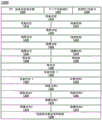
In one embodiment, a number of sideband signals may be configured into a single packet, e.g., via a semantic layer, for communication via an integrated sideband mechanism (or in-band mechanism). In one embodiment, table 3 below shows various signals that may be present in one embodiment. In the illustrated table, the logical direction of the signals is illustrated by arrows, where an up arrow is defined as the direction towards the host (e.g., root complex) and a down arrow is defined as the direction towards the device (e.g., peripheral device (e.g., radio solution)).
TABLE 3
Device presentation ↓
Normal power supply ↓
Power off ↓
Reference clock normal ↓
Basic reset ↓
Configuration ready ↓ -
Preparation training ↓
Begin training ↓
L1pg request ↓
L1pg rejects ↓
L1pg authorization ↓
OBFF CPU activity ↓
OBFF DMA↓
OBFF idle ↓
Awakening ↓ @
Acknowledgment reception ↓ of handshake
Referring now to fig. 6, fig. 6 illustrates a flow diagram of various states of a sideband mechanism in accordance with an embodiment of the present invention. As shown in fig. 6, these various states may be with respect to a root complex (e.g., a host control operation). State diagram 600 may provide control of various states via a host. As can be seen, operation begins in a pre-boot state 610 where a presence signal may be communicated. It is noted that the presence signal may be as described above with respect to the link management operation. Control then passes to an enable state 620 where various signals, i.e., a power normal signal, a reset signal, a reference clock status signal, and a ready training signal, may be passed. It is noted that all of these signals may be communicated via a single packet, where each of these signals may correspond to an indicator or field of the packet (e.g., a one-bit indicator of the packet).
Still referring to fig. 6, control next passes to an active state 630, where in the active state 630, the system may be in an active state (e.g., S0), the corresponding device (e.g., downstream device) may be in an active device state (e.g., D0), and the link may be in an active, stopped, or low power state (e.g., L0, L0S, or L1). As can be seen, in this state, various signals can be communicated, including: an OBFF signal, a clock request signal, a reference clock signal, a request L0 signal, and a ready-to-train signal.
Next, control may pass to low power state 640, for example, after the above signals are performed. As can be seen, in the low power state 640, the system may be in an active state while the device may be in a relatively low latency low power state (e.g., D3 hot). Additionally, the link may be in a given low power state (e.g., L2 or L3). As seen in these states, the signals passed via the integrated sideband packets may include: a wake-up signal, a reset signal, and a power-on-normal signal.
As the system enters a deeper low power state, a second low power state 650 may be entered (e.g., when the system is in the S0 state and the device is in the D3 cold state, while the link is similarly in the L2 or L3 states). As can be seen, the same wake up, reset and power ok signals can be passed. Also visible in FIG. 6, the same signals may occur in the deeper low power state 660 (e.g., system low power state, S3) and the device low power state (e.g., D3 cold) and the same link low power states L2 and L3. Although a particular set of sideband information communicated is shown, it is to be understood that the scope of the present invention is not so limited.
Thus, embodiments provide a scalable hierarchy that can balance simplicity with low latency and flexibility. In this way, existing sideband signals and additional sideband signals can be replaced with fewer signals and future extensions of the sideband mechanism can be implemented without adding more pins.
Referring now to fig. 7, fig. 7 shows a flow diagram of a method according to an embodiment of the invention. As shown in fig. 7, method 700 may be used to communicate data via an aggregated protocol stack that includes upper and lower layers of one communication protocol (e.g., of different communication protocols)Physical layer). In the illustrated example, it is assumed that the aggregated protocol stack is as described above, i.e., with PCIeTMThe transaction and data link layers above the protocol and the physical layers of different specifications (e.g., the MIPI specification). Of course, additional logic may also be present to enable the two communication protocols to be aggregated into a single protocol stack, such as the logic and circuitry discussed above with respect to fig. 4.
As seen in fig. 7, method 700 may begin by receiving a first transaction in a protocol stack of a first communication protocol (block 710). For example, various logic of the root complex (e.g., core, other execution engine, etc.) attempts to send information to another device. Thus, this information may go to the transaction layer. As seen, control passes to block 720 where the transaction may be processed and provided to the logical portion of the PHY of the second communication protocol. The processing may include various operations discussed above with respect to the flow of fig. 4, where different operations for receiving data, performing flow control, link operations, packet operations, etc. may occur. In addition, various operations may occur for providing data link layer packets to the PHY. Control then passes to block 730 where the first transaction may be converted to a second format transaction in the logical portion of the PHY. For example, any translation of the symbols may be performed (as needed). Additionally, various conversion operations may occur that are completed for thereby converting the transaction into a format for transmission over the link. Accordingly, control may pass to block 740 where the second formatted transaction may be communicated from the PHY to the device via the link. By way of example, the second format transaction may be serialized data after line encoding, serialization, and the like. While the embodiment of fig. 7 is shown at such a high level, it is to be understood that the scope of the present invention is not so limited.
Referring now to FIG. 8, FIG. 8 illustrates a block diagram of components present in a computer system, according to an embodiment of the invention. As shown in fig. 8, system 800 may include many different components. These components may be implemented as ICs, portions thereof, discrete electronics or other modules adapted to a circuit board (e.g., a motherboard or insertable card of a computer system), or as components incorporated into a chassis of a computer system. It is also noted that the block diagram of FIG. 8 is a high-level view intended to illustrate many of the components of a computer system. However, it is to be understood that additional components may be present in certain implementations, and further, that different arrangements of the illustrated components may occur in other implementations.
As seen in fig. 8, processor 810, which may be a low power multicore processor socket (e.g., an ultra low voltage processor), may serve as a main processing unit and central hub for communicating with various components of the system. Such a processor may be implemented as a SoC. In one embodiment, processor 810 may be based on Architectural coreTMSuch as i3, i5, i7 or another such processor available from Intel Corporation, Santa Clara, CA. However, it is to be understood that other low power processors (e.g., available from Advanced Micro Devices, Inc. (AMD) of Sunnyvale, CA, an ARM-based design from ARM Holdings, Ltd, or a MIPS-based design from MIPS technologies, Inc. of Sunnyvale, CA), or their authorizers or adopters may be substituted for the present in other embodiments, e.g., the apple a5 processor.
The processor 810 may be in communication with a system memory 815, which in embodiments may be implemented via a plurality of storage devices to provide a given amount of system memory. By way of example, the memory may be based on a Joint Electronic Device Engineering Council (JEDEC) Low Power Double Data Rate (LPDDR) -based design, e.g., the current LPDDR2 standard, published in 2009 on 4 months, according to JEDEC JESD 209-2E, or a new generation LPDDR standard known as LPDDR3, which LPDDR3 would provide an extension to LPDDR2 for increased bandwidth. By way of example, 2/4/8 Gigabytes (GB) of system memory may be presented and coupled to processor 810 via one or more memory interconnects. In various implementations, the individual storage devices may have different packet types, for example, Single Die Package (SDP), Dual Die Package (DDP), or Quad Die Package (QDP). In some embodiments, these devices may be soldered directly to the motherboard for providing a lower profile solution, while in other embodiments the devices may be configured as one or more memory modules that may be coupled to the motherboard sequentially through a given connector.
To provide persistent storage of information (e.g., data, applications, one or more operating systems, etc.), a mass storage device 820 may also be coupled to the processor 810. In various embodiments, to enable thinner and lighter system designs and to improve the responsiveness of the system, the mass storage device may be implemented via an SSD. However, in other embodiments, the mass storage device may be primarily implemented using a Hard Disk Drive (HDD) with a smaller number of SSD storage devices as SSD cache, to enable non-volatile storage of context state and other such information during power down events, so that fast power-up may occur upon re-initialization of system activity. As shown in fig. 8, flash device 822 may be coupled to processor 810, for example, via a Serial Peripheral Interface (SPI). The flash memory device may provide non-volatile storage of system software, including: basic input/output software (BIOS) of the system, and other firmware.
Various input/output (IO) devices may be present within the system 800. Specifically shown in the embodiment of fig. 8 is a display 824, which display 824 may be a high definition LCD or LED panel disposed within a cover portion of the chassis. The display panel may also provide a touch screen 825, e.g., adaptively external to the display panel, such that user input may be provided to the system to enable desired operations, e.g., display of information, access of information, etc., via user interaction with the touch screen. In one embodiment, display 824 may be coupled to processor 810 via a display interconnect, which may be implemented as a high performance graphics interconnect. Touch screen 825 may be coupled to processor 810 via another interconnect, which in embodiments may be I2And C is interconnected. As further shown in FIG. 8, in addition to touch screen 825, user input in the form of touch may also be providedTo occur via a touch pad 830, which touch pad 830 may be configured within the chassis and may also be coupled to the same I as the touch screen 8252And C is interconnected.
Various sensors may be present within the system and may be coupled to the processor 810 in different ways for perceptual computing and other purposes. Certain inertial and environmental sensors may pass through sensor hub 840 (e.g., via I)2C interconnect) is coupled to processor 810. In the embodiment shown in fig. 8, these sensors may include accelerometer 841, Ambient Light Sensor (ALS)842, compass 843, and gyroscope 844. In one embodiment, other environmental sensors may include one or more thermal sensors 846, which one or more thermal sensors 846 may be coupled to the processor 810 via a system management bus (SMBus) bus. It is also understood that one or more sensors may be coupled to the processor 810 via an LPS link in accordance with embodiments of the present invention.
As also seen in fig. 8, various peripheral devices may be coupled to processor 810 via a Low Pin Count (LPC) interconnect. In the illustrated embodiment, the various components may be coupled by an embedded controller 835. Such components may include a keyboard 836 (e.g., coupled via a PS2 interface), a fan 837, and a thermal sensor 839. In some embodiments, touchpad 830 may also be coupled to EC 835 via a PS2 interface. Additionally, a secure processor (e.g., a Trusted Platform Module (TPM)838), e.g., according to Trusted Computing Group (TCG) TPM specification version 1.2 (10/2/2003), may also be coupled to the processor 810 via the LPC interconnect.
The system 800 may communicate with external devices in various ways, including wirelessly. In the embodiment shown in fig. 8, various wireless modules are presented, each of which may correspond to a radio configured for a particular wireless communication protocol. One way of wireless communication over short distances (e.g., near field) may be via a Near Field Communication (NFC) unit 845, which in one embodiment may communicate with the processor 810 via an SMBus. It is to be noted that devices that are close to each other via the NFC unit 845 can communicate. For example, a user may enable the system 800 to communicate with another, e.g., portable device (e.g., a user's smartphone) via adjusting the two devices into a close relationship and enabling the transfer of information (e.g., identification information, payment information), data (e.g., image data), and so forth. Wireless power transfer may also be performed using an NFC system.
As further seen in fig. 8, additional wireless units may include other short-range wireless engines including a WLAN unit 850 and a bluetooth unit 852. Wi-Fi in accordance with a given Institute of Electrical and Electronics Engineers (IEEE)802.1 standard may be implemented using WLAN unit 850TMCommunication, while short-range communication via the bluetooth protocol may occur via bluetooth unit 852. These units may communicate with processor 810 via, for example, a USB link or a Universal Asynchronous Receiver Transmitter (UART) link. Alternatively, the units may be coupled to processor 810 via an interconnect via a low power interconnect (e.g., an aggregated PCIe/MIPI interconnect as described herein), or another such protocol (e.g., serial data input/output (SDIO) standard). Of course, the actual physical connection between these peripherals (which may be configured on one or more plug-in cards) may serve as a motherboard-compliant NGFF connector.
Additionally, wireless wide area communication (e.g., according to a cellular or other wireless wide area protocol) may occur via a WWAN unit 856, which may in turn be coupled to a Subscriber Identification Module (SIM) 857. In addition, to enable receipt and use of location information, a GPS module 855 may also be present. It is noted that in the embodiment shown in fig. 8, the WWAN unit 856 and the integrated capture device (e.g., camera module 854) may be via a given USB protocol (e.g., USB 2.0 or 3.0 link or UART or I)2Protocol C) to communicate. Likewise, the actual physical connection of these units may be via an adaptation of the NGFF add-in card to the NGFF connector configured on the motherboard.
To provide audio input and output, the audio processor may be implemented via a Digital Signal Processor (DSP)860, which DSP 860 may be coupled to the processor 810 via a high-definition audio (HAD) link. Likewise, the DSP 860 may communicate with an integrated coder/decoder (CODEC) and microphone 862, which in turn may be coupled to an output speaker 863, which may be implemented within the chassis. Also, a microphone and CODEC 862 can be coupled to receive audio inputs from the microphone 865, which in embodiments can be implemented via a dual array microphone for providing high quality audio inputs to enable voice controlled control of various operations within the system. Note also that audio output may also be provided from the microphone CODEC 862 to the headphone jack 864.
Thus, embodiments may be used in many different environments. Referring now to fig. 9, fig. 9 illustrates a block diagram of an example system 900 that can be used with embodiments. As can be seen, the system 900 may be a smart phone or other wireless communicator. As shown in the block diagram of fig. 9, the system 900 may include a baseband processor 910, which baseband processor 910 may be a multi-core processor that may manage both baseband processing tasks and application processing. As such, the baseband processor 910 may perform various signal processing with respect to communications, as well as perform computing operations for the device. In turn, baseband processor 910 may be coupled to a user interface/display 920, which user interface/display 920 may be implemented in some embodiments by a touch screen display. In addition, baseband processor 910 may be coupled to a memory system that includes non-volatile memory (i.e., flash memory 930) and system memory (i.e., Dynamic Random Access Memory (DRAM)935) in the embodiment of fig. 9. As further seen, baseband processor 910 may be further coupled to a capture device 940 (e.g., an image capture device that may record video and/or still images).
To enable transmission and reception of communications, various circuits may be coupled between the baseband processor 910 and the antenna 980. Specifically, a Radio Frequency (RF) transceiver 970 and a Wireless Local Area Network (WLAN) transceiver 975 may be present. In general, RF transceiver 970 may be configured to communicate in accordance with a given wireless communication protocol (e.g., 3G or 4G wireless communication protocol (e.g., in accordance with Code Division Multiple Access (CDMA), Global MobileCommunication system (GSM), Long Term Evolution (LTE), or other protocol)) to receive and transmit wireless data and calls. Other wireless communications may also be provided, such as reception or transmission of radio signals (e.g., AM/FM or Global Positioning Satellite (GPS) signals). Additionally, local wireless signals (e.g., according to Bluetooth)TMA standard or IEEE 802.11 standard (e.g., 802.11a/b/g/n)) may also be implemented via WLAN transceiver 975. It is noted that the link between baseband processor 910 and one or both of transceivers 970 and 975 may be via a low power aggregate interconnect that interconnects PCIeTMThe functionality of the interconnect and the low power interconnect (e.g., MIPI interconnect) are combined and mapped. While the embodiment of fig. 9 is shown at such a high level, it is to be understood that the scope of the present invention is not so limited.
With commonly used interconnects (e.g. PCIe)TMOver PCIeTMIn contrast to link operating modes (e.g., width and speed) that are negotiated during link training), embodiments do not perform such negotiations. Because of PCIeTMThe protocol is based on negotiation so the link determines the most common mode of operation supported and then operates the link in that mode. This becomes more complicated when the link supports asymmetric lines and speeds.
In contrast, embodiments provide an architectural protocol for dynamically changing the link operating mode, which can be done during runtime and does not cause the link to enter a link down state. According to the architectural protocol, during initialization, a link mode of operation supported by an agent is discovered on the other end of the link; software or hardware may then determine the most common mode of operation; when the link mode of operation is to be changed, the proxies at both ends of the link exchange messages for requesting and responding to the mode change of operation. It is noted that link retraining is simplified because accurate parameters are passed so that both ends of the link are accurately aware of the new parameters used to operate the link.
As discussed above, in some embodiments, the physical layer on one of the two sides of the link may be an M-PHY. In such embodiments, the link may include a serial line carrying a differential Pulse Width Modulation (PWM) signal. The differential PWM signals communicated over the link may be within one or more data rate ranges of the M-PHY specification (referred to as "GEAR"). For example, the link may operate at GEAR 1(3 megabits per second (Mbps) to 9Mbps), GEAR 2(6Mbps to 18Mbps), GEAR 3(12Mbps to 36Mbps), GEAR 4(24Mbps to 72Mbps), GEAR 5(48Mbps to 144Mbps), GEAR 6(96Mbps to 288Mbps), GEAR7(192Mbps to 576Mbps), or the like. Using embodiments of the present invention, dynamic link reconfiguration may occur to operate at a selected one of these ranges (or other ranges).
Embodiments support dynamic link bandwidth changes such that both ends of the link agree to change link parameters to support the new bandwidth. There are two link configuration scenarios: after power-on reset or according to link initial configuration of a link disconnection state; and run-time reconfiguration of the link without experiencing link disconnection. The link initial configuration utilizes the LS mode of operation, in which only a single line (e.g., line 0) is used. In some embodiments, the link reconfiguration is optional and may be initiated during normal operation of the link.
For reconfiguration, both ends of the link may be set for reconfiguration triggers (RCTs) and they apply only to those registers that are RCT capable. A higher layer protocol handshake mechanism may be used to read and write offline registers and set the RCT. In an embodiment, RCT is triggered when all active lines enter SAVE state. Note that the PHY offline registers may be written directly by software or implicitly by hardware (protocol level handshake completion). When a configuration change occurs (e.g., a width or speed change occurs), the agent initiating the change requests the configuration change.
The example of fig. 10 shows port a initiating a reconfiguration request and the acknowledgement of the initiated request by port B, followed by entry into a recovery and to a STALL state on all lines. The RCT is triggered and the new configuration settings take effect. In some embodiments, there may be two distinct methods for obtaining reconfiguration: using Data Link Layer Packets (DLLPs) and using training sequences.
As seen in fig. 10, port a of a PHY unit, which may have a first device (e.g., an upstream device), communicates with port B of a second device (which may be a downstream device) via a physical link. As can be seen, in the active link state (e.g., L0), port a may pass multiple DLLPs (i.e., bandwidth change request DLLPs) to port B.
In response to such packets, port B may pass multiple acknowledgement DLLPs (i.e., multiple bandwidth change acknowledgement DLLPs) back to port a via its PHY unit. In turn, port A may cause a stall condition of the link by initiating a transmission stall condition via EIOS, followed by a DIF-N signal. In turn, port B may pass a similar signal (i.e., EIOS) with the DIF-N signal following it. In response to such communication, both devices may communicate a high impedance signal to bring the link into the HIBERN8 state. Also, RCT may occur for link reconfiguration and thereafter, the link may exit via delivery of the DIF-N signal with the new settings. While the embodiment of fig. 10 is shown at such a high level, it is to be understood that the scope of the present invention is not so limited.
For DLLP-based reconfiguration, during the initialization process, software will read the function registers at both ends of the link and update the registers of each port with the functions of the link partner. For a requester that initiates reconfiguration of link parameters, the requester continuously transmits BwChange _ Request DLLP messages. It is noted that the requester may not make any new configuration request until the first link configuration request is completed. The requester then waits for a BwChange Acknowledge DLLP message. Upon receiving the confirmation message, the requestor transmits the EIOS and sets the RCT event. The event causes a register to be written using the appropriate M-PHY parameters, and the RCT causes the parameters to be applied to the link. If the RCT bit is set, the requester transitions all lines to the enter HIBERN8 state and waits for all receiver lines to enter HIBERN 8. Once both transmitter and receiver lines are in the HIBERN8 state, the requester makes the appropriate configuration change and obtains the RCT.
For remote requested reconfiguration of link parameters, the receiver continuously transmits BwChange acknowledmedllp messages until either EIOS is received or the received line begins to transition to HIBERN 8. The RCT bit is then set. When the RCT bit is set, the receiver transmits the EIOS and then transitions all lines into the HIBERN8 state. The receiver is allowed to immediately enter HIBERN 8; the receive chain may begin reconfiguring its offline registers. Once both the transmitter and receiver are in the HIBERN8 state, the receive chain then performs RCT. Exit from HIBERN8 state then occurs with the updated parameters.
Embodiments support functionality for changing link bandwidth without experiencing a link disconnection. Dynamic link reconfiguration supports changing link bandwidth by changing the ratio sequence or high speed gear on the modules on both sides of the link identically and changing the number of configured wires per sub-link. Allowing the link width to change to be asymmetric. I.e. allowing the module to be configured with a different number of TX-lines and RX-lines. By following PCIeTMThe link bandwidth notification mechanism of (1) notifies software of any rate sequence or link speed, and link width changes.
In an embodiment, the link bandwidth parameters that may be reconfigured during runtime include: a ratio sequence (A or B); a high-speed gear; and a sublink width. Link ratio sequencing and link speed management may be at LTSSM and in accordance with PCIeTMIs coordinated between the software link observation and control mechanisms.
In an embodiment, the target link speed field in the link control 2 register sets an upper bound for the link speed. The upstream component attempts to maintain the link at the target link speed or at the fastest speed supported by both components on the link (as reported by the values in the training set), whichever is lower, except as described below.
If dynamic ratio sequence reconfiguration is implemented, the component may autonomously adjust the link ratio sequence and use a dynamic link reconfiguration function for requesting a ratio sequence change.
If the hardware autonomous speed disable bit in the link control 2 register is cleared, the component may use implementation-specific criteria to autonomously adjust the link ratio sequence and link high speed gear. The component may reduce or increase the link speed by removing or adding the corresponding link high speed gear from the list of supported high speed gears advertised in the training set transmitted by the component. The criteria for removing or adding a high gear is implementation specific and does not depend on the setting of the hardware autonomous speed disable bit.
By setting the value in the target link speed field in the upstream component, the software can limit the maximum speed of link operation and set the preferred link speed. After modifying the value in the target link speed field, the software triggers link retraining by writing a predetermined value to the retraining link bit.
Link width management may be in LTSSM and in accordance with PCIeTMIs coordinated between the software link observation and control mechanisms. The upstream component attempts to configure each sublink as the maximum number of lines supported by the mport on the opposite side of the link.
If the hardware autonomous width disable bit in the link control registers of both components is cleared, the components are allowed to autonomously request a sublink width change using implementation specific criteria. The component is allowed to reduce or increase the sublink width by removing or adding the corresponding TX line width and RX line width settings from the list of supported sublink width settings advertised in the training set transmitted by the component. The criteria for removing or adding link width settings may be implementation specific and not dependent on the setting of hardware autonomous width disable bits.
Referring now to fig. 11, fig. 11 shows a timing diagram illustrating a link configuration initiated by a downstream port, according to an embodiment of the invention. As shown in fig. 11, link reconfiguration may begin with a downstream port requesting a change by passing a training ordered set (TS1) with a bandwidth change. The message may be sent a predetermined number of times. In response, the upstream component may receive these and pass the same message a predetermined number of times. After being parsed by the downstream port, it may send a training ordered set TS2 with parsed values, while the upstream port may pass a training ordered set TS2 message with bandwidth changes and identification of supported values. After entering the stopped state (e.g., via communication of EIOS and DIF-N signals), the link may exit the stopped state with the new configuration settings.
To train sequence-based reconfiguration, the component initiates dynamic link reconfiguration by sending a training ordered set TS1 with a bandwidth change bit setting. The component that initiates the bandwidth change request sets the fields in the training ordered set for the requested ratio sequence, high gear, TX line width, and RX line width. Once the dynamic link reconfiguration process begins, the component may not change the requested bandwidth setting in the training ordered set.
For link bandwidth changes initiated by upstream components, downstream components respond with a training ordered set TS1 with a bandwidth change request bit set based on successfully receiving TS 1. The downstream component sets the TS1 field based on support for the ratio sequence, high gear, and sublink width.
The upstream component is responsible for determining the new ratio sequence, high speed gear and sublink width according to the per link reconfiguration rules as described above. These new settings are communicated by the upstream component by transmitting TS2 with the bandwidth change bit setting and including the new bandwidth setting. The downstream components acknowledge receipt of the new bandwidth setting by transmitting a training set TS2 with a link bandwidth acknowledge bit setting.
When a component's attempt to negotiate with a particular link bandwidth is rejected, the component is not allowed to attempt a dynamic link reconfiguration within a predetermined time interval, from the last attempt back after L0 or until other components on the link initiate a link bandwidth request.
As part of the dynamic link reconfiguration, the upstream components make decisions regarding new target high speed gears, ratio sequences and widths based on the following rules. The upstream component uses the TS2 ordered set for passing the value selected for the operation. The upstream component makes the decision to select a new link bandwidth value by comparing the value in TS1 with the link bandwidth change bit setting received from the downstream component with the value supported by the upstream component (independent of the value that the upstream component may have used in TS1 to request a link bandwidth change).
If the requested new high gear is different from the current high gear and the components on both sides of the link have at least one commonly supported high gear, the new high gear will be the most commonly supported high gear.
If the requested new high gear is different from the current high gear and the components on both sides of the link do not have at least one commonly supported high gear, the new high gear will remain the current high gear.
If the requested new sublink width is different from the current sublink width and the components on both sides of the link have at least one commonly supported sublink width, then the new sublink width will be the most commonly supported sublink width.
If the requested new sublink width is different from the current sublink width and the components on both sides of the link do not have at least one commonly supported sublink width, the new sublink width will remain the current sublink width.
If the requested new ratio sequence is different from the current ratio sequence and the components on both sides of the link support the new ratio sequence, the new ratio sequence will be the requested ratio sequence.
Note that when a request is made to change the ratio sequence, the requesting component sets the corresponding ratio sequence support bit for the new ratio sequence within the training sequence and clears the ratio sequence support bit for the current ratio sequence. The responding component then sets the corresponding ratio sequence support bit for its supported ratio sequence, which may be more than one ratio sequence.
If the requested new ratio sequence is different from the current ratio sequence and the components on both sides of the link do not support the new ratio sequence, the new ratio sequence will remain the current ratio sequence.
In some embodiments, high speed gears, ratio sequences, and sublink width changes may be requested simultaneously.
Referring now to table 4, table 4 shows TS1 ordered sets according to one embodiment of the invention.
TABLE 4


Referring now to table 5, table 5 shows TS2 ordered sets according to one embodiment of the invention.
TABLE 5


Referring now to FIG. 12, FIG. 12 shows a block diagram illustrating a recovery sub-state machine according to an embodiment of the invention. As shown in FIG. 12, the resume sub-state machine may enter the resume from the L0 or L1 states enter state 1210. From the resume. enter state 1210, depending on the received value, control may transition to the resume. reconfigure substate 1220, and then enter the configure. update substate.
Alternatively, control may transition from the sub-state 1210 to the resume.done sub-state 1230, and thereafter, to the resume.idle state 1240 (the resume.reconfigure sub-state may enter the resume.idle state 1240). The recovery substate machine may then exit from the recovery substate 1240 and control may transition to the L0 active state.
In the recovery-enter state machine, the transmitter transmits TS1 ordered sets on all configured TX lines. The component initiating the bandwidth change transmits a TS1 ordered set with link bandwidth change bit settings and updated link bandwidth parameters on all configured TX lines. The component that did not initiate the bandwidth change transmits a TS1 ordered set with link bandwidth change bit settings based on receiving two or more TS1 or TS2 ordered sets with link bandwidth change bit settings in this state. The link bandwidth parameters reflect the supported configuration.
The next state is resume.reconfiguration, which may occur if a predetermined number (e.g., 8) of consecutive TS1 or TS2 ordered sets are received on all configured RX lanes, the TS1 or TS2 ordered sets having link bandwidth change bit settings that match the link bandwidth change bits on the transmit side.
The next state is resume complete, which may occur if a predetermined number (e.g., 8) of consecutive TS1 or TS2 ordered sets are received on all configured RX lanes, the TS1 or TS2 ordered sets having link bandwidth change bit clears that match the link bandwidth change bit on the transmit side.
Otherwise, after a predetermined timeout period, which may be 24 milliseconds (ms) in an embodiment, the next state is detection. At this point, all configured TX lines send at least one EIOS, terminate HS-BURST, and enter STALL. Once all configured TX and RX lines have entered STALL, RCT is triggered for moving the configured TX and RX lines to HIBERN 8.
In the recovery-reconfiguration state machine, for downstream ports, if a link bandwidth change is required, the transmitter transmits a TS2 ordered set with a link bandwidth change bit setting and a link bandwidth change acknowledge bit setting on all configured TX lanes based on the TS1 ordered set negotiation in the recovery-entry state and the rules as described for dynamic link reconfiguration, otherwise, the link bandwidth change bit is cleared.
If a link bandwidth change is to occur, the link bandwidth parameters in the TS2 ordered set reflect a new target link bandwidth that is determined based on the rules described in the dynamic link reconfiguration. If 2 or more ordered sets of TS2 are received with a link bandwidth change bit setting and a link bandwidth change acknowledgment bit setting, the uplink port receives a new target link bandwidth. If no link bandwidth change has occurred, the next state is immediately resume idle after all configured RX lanes have received 8 consecutive TS2 ordered sets with link bandwidth change bit set and link bandwidth change acknowledge bit clear, and after receiving one TS2 ordered set, and after sending 16 TS2 ordered sets with link bandwidth change bit set and link bandwidth change bit clear.
For the uplink port, the transmitter transmits the TS2 ordered set with the link bandwidth change bit setting and the link bandwidth change acknowledgement bit clear on all configured TX lines until the transmitter receives 2 or more TS2 ordered sets with the link bandwidth change bit setting and the link bandwidth change acknowledgement bit setting on all configured RX lines, upon which the transmitter starts transmitting the TS2 ordered set with the link bandwidth change bit setting and the link bandwidth change acknowledgement bit setting on all configured TX lines. The link bandwidth parameter in the TS2 ordered set continues to reflect the supported configuration whether the link bandwidth change acknowledgment bit is set or cleared. The next state is resume-idle immediately after all configured RX lanes have received 8 consecutive TS2 ordered sets with link bandwidth change bit setting and link bandwidth change acknowledge bit clear, and after having received one TS2 ordered set, and after having sent 16 TS2 ordered sets with link bandwidth change bit setting and link bandwidth change acknowledge bit clear.
For both downstream and upstream ports, if a link bandwidth change is selected, eight consecutive TS2 ordered sets with link bandwidth change bit setting, link bandwidth change acknowledge bit setting are received on all configured RX lines, after receiving one TS2 ordered set, 16 TS2 ordered sets with link bandwidth change bit setting and link bandwidth change acknowledge bit setting are sent and the next state is configuration immediately after all configured TX and RX lines have entered HIBERN8 state. At this point, all configured TX lines enter a STALL state and RCT is triggered to change the mode of operation to a new high speed gear and ratio sequence and once all configured TX and RX lines enter the STALL state, the TX and RX lines are switched to HIBERN 8.
Otherwise, after a predetermined timeout period (which may be 2ms), the next state is detect (as described above).
In the resume complete state machine, the transmitter transmits TS2 ordered sets on all configured TX lines. Note that before leaving this state, line-to-line deskewing is complete. The next state is the resume idle state immediately after all configured RX lanes receive 8 consecutive TS2 ordered sets and after 16 TS2 ordered sets are sent after receiving one TS2 ordered set. Otherwise, the next state is detection after a predetermined timeout, as described above.
In a recovery idle state machine, if indicated, the next state is a disable state. Note that "if there is an indication" applies to the downstream port managed by the higher layer for enabling the disable link bits (TS1 and TS2) on the link. If so, the next state is a hot reset. Note that "if there is an indication" applies to downstream ports managed by higher layers for validating the warm reset bits (TS1 and TS2) on the link. After any configured RX lane receives a TS1 ordered set with a disable link bit (which is valid in two consecutively received TS1 ordered sets), the next state is immediately the disable state. Note that this behavior applies only to the upstream ports. After any configured RX line receives a TS1 ordered set with a warm reset bit (which is valid in two consecutive TS1 ordered sets), the next state is immediately the warm reset. Idle data is transmitted on all configured TX lines. If indicated as the other states listed above, no idle data need be sent before transitioning to the other states. If eight consecutive symbols of idle data are received on all configured lines and 16 idle data symbols are sent after receiving one idle data symbol, the next state is the L0 state. Otherwise, the next state is detection after a predetermined timeout, as described above.
As described herein, embodiments enable conventional PCIeTMThe protocol stack can be mapped on non-PCIeTMCommunication takes place over the physical layer and the link. Embodiments described herein are directed to a PHY unit (M-PHY) according to the MIPI specification. Of course, the embodiments are not limited thereto.
In order to respond to the existing PCIeTMSoftware stack provides software compatibility, and embodiments may provide physical layer over different protocols with PCIeTMMapping of various control and status information of the protocol. More specifically, embodiments herein may provide mechanisms for enabling a bus driver accessing a configuration space to use information in the configuration space to manage and control a given link for performing various operations along the link, including: initialization, configuration/reconfiguration, communication, etc.
Referring now to fig. 13, fig. 13 shows a block diagram of a functional structure according to an embodiment of the present invention. As shown in fig. 13, functional structure 1300 may be a data structure stored, for example, in a configuration space of a device, which may include a plurality of registers for storing function, configuration, status, and control information used by various agents, including one or more bus drivers. Of course, in other embodiments, the functional structure may be stored in other locations of the device.
As seen in fig. 13, structure 1300 may include: PCIe devicesTMFunction register 1305, next function pointer register 1307, and PCIeTMThe function identifier registers 1309, as shown, may be present in a first set of bytes. Next for device information, device function registers 1310 may be presented, along with device status registers 1314 and device control registers 1312. For link information, link function registers 1315 may be provided, along with link status registers 1325 and link control registers 1320. For slot information, slot function registers 1313 may be provided, along with slot status registers 1304 and slot control registers 1332. For root information, such as a root complex device, root function registers 1338 and root control registers 1336 may be provided, along with root status registers 1340.
To provide additional information, the functional fabric 1300 may include additional information for devices, links, and slots. As can be seen, in particular, additional device information may be provided as device function 2 register 1350, device status 2 register 1354, and device control 2 register 1352. For additional link information, a link function 2 register 1360 may be provided, along with a link status 2 register 1364 and a link control 2 register 1362. Slot function 2 registers 1370, slot status 2 registers 1374, and slot control 2 registers 1372 may also be provided for the purpose of additional slot information. Finally, functional architecture 1300 may be a control of link width and speed as described herein, which functional architecture 1300 may further enableInvolving rapid movementTM(fast moving)TM) Function and control registers 1380. While shown with this particular illustration in the embodiment of fig. 13, understand the scope of the present invention is not limited in this regard. For example, in some embodiments, registers 1380 may be part of a separate functional structure.
To enable information in the extended functional architecture of FIG. 13 to be used for NAND PCIeTMPhysical layer connection and still connect to existing PCIeTMSoftware stacks are compatible, and values for certain register interfaces may be provided to map at least some of these extended function registers to non-PCIe registers that provide different link speeds, gears, and link widthsTMAnd a physical layer.
Referring now to Table 6, Table 6 shows a list of certain functional registers and recommended settings for certain fields of the registers for enabling an existing software stack to be used with non-PCIeTMThe physical layer makes the connection. Although the register settings shown in table 6 are for interfacing with an M-PHY according to the MIPI specification, it is to be understood that the scope of the present invention is not so limited.
TABLE 6


It is noted that the information in these fields of the registers of the functional structure may be used for the purposes of the operations performed by the device drivers and state machines described herein. Further, it is noted that the recommended settings for some of these fields identify or refer to the supported link speed vector of the link function 2 register. This can be achieved in different ways. For example, the value from the vector may be copied to the field of the indicated register, or the values of the fields of the different registers (e.g., the maximum link speed field of the link function register) may have values that are thus used as pointers to the supported link speed vector field of the link function 2 register.
Referring now to FIG. 14, shown is a flow diagram of a method in accordance with another embodiment of the present invention. In particular, the method 1400 of fig. 14 may be used, for example, by a device driver or other logic to determine certain settings (e.g., maximum link speed, link width, etc.) using information in multiple ones of these configuration registers of the functional structure. For purposes of illustration, it is assumed that the required configuration information obtained and used in fig. 14 is for maximum link speed, however, it is to be understood that the scope of the present invention is not so limited.
The method 1400 may begin at block 1410 by accessing a first field of a first link function register with a device driver. For example, referring back to table 6, the first link function register may be a link function register and the particular field to be accessed may be a maximum link speed field. Next, at block 1420, this field may be used as a pointer value to a location in a second link function register. More specifically, the value of this first field may indicate a particular location within another configuration register (e.g., the link function 2 register of table 6), thereby indicating a particular bit within the supported link speed vector.
Control thus passes to block 1440 where, in block 1440, the second link function register may be accessed with a device driver for obtaining information at the identified location. Assume in this example that the first field of the first link function register has a value of 01b, indicating that it points to bit 1 of the supported link speed vector. Thus, at block 1440, the device driver may access the register and obtain the value of this bit (assuming set), which indicates that the link can support high speed, notch 3 speed (HS-G3).
Still referring to fig. 14, next using this information obtained at the indicated location, a link operation may be performed. For example, based on the determined maximum link speed setting, the device driver may initiate a link reconfiguration or other mechanism for operating at the indicated maximum link speed. While the embodiment of fig. 14 is shown at such a high level, it is to be understood that the scope of the present invention is not so limited.
Embodiments may be used in many different types of systems. For example, in one embodiment, a communication device may be arranged to perform the various methods and techniques described herein. Of course, the scope of the invention is not limited to communication devices, but rather other embodiments may be directed to other types of apparatuses or one or more machine-readable media (including in response to instructions executing on a computing device) for processing instructions to cause a device to perform one or more of the methods and techniques described herein.
Embodiments may be implemented in code and may be stored in a non-transitory storage medium having stored thereon instructions which can be used to program a system for executing the instructions. The storage medium may include, but is not limited to: any type of disk including floppy disks, optical disks, Solid State Drives (SSDs), compact disk read-only memories (CD-ROMs), compact disk rewritables (CD-RWs), and magneto-optical disks, semiconductor devices such as read-only memories (ROMs), Random Access Memories (RAMs) such as Dynamic Random Access Memories (DRAMs), Static Random Access Memories (SRAMs), erasable programmable read-only memories (EPROMs), flash memories, electrically erasable programmable read-only memories (EEPROMs), magnetic or optical cards, or any other type of media suitable for storing electronic instructions.
While the present invention has been described with respect to a limited number of embodiments, those skilled in the art will appreciate numerous modifications and variations therefrom. It is intended that the appended claims cover all such modifications and variations as fall within the true spirit and scope of this present invention.
Claims (24)
1. An apparatus for interfacing a communication protocol, comprising:
a protocol stack for a peripheral component interconnect express, PCIe, communication protocol, the protocol stack comprising a transaction layer and a link layer;
a physical unit coupled to the protocol stack to provide communication between the apparatus and a device coupled to the apparatus via a physical link, the physical unit comprising a physical unit circuit M-PHY according to Mobile industry processor interface, MIPI, specification and a logical layer for interfacing the protocol stack with the physical unit circuit,
the logical layer includes a Link Training and Status State Machine (LTSSM) configured to manage the physical link and perform link training of the physical link and support multi-way configuration, asymmetric link width configuration, and dynamic bandwidth scalability of the physical link; and
a functional fabric including a plurality of registers, each register of the plurality of registers for storing at least one of functional information, state information, and control information, and an extension including a mobile PCIe functional register for storing link speed information.
2. The apparatus of claim 1, wherein the first field of the mobile PCIe function register is to store a first value indicating that a first speed gear is supported.
3. The apparatus of claim 2, wherein the second field of the mobile PCIe function register is to store a second value indicating that a second high speed gear is supported.
4. The apparatus of claim 3, wherein the third field of the mobile PCIe function register is to store a maximum transmit line width function.
5. The apparatus of claim 4, wherein the fourth field of the mobile PCIe function register is to store a maximum receive line width function.
6. The apparatus of claim 5, wherein the LTSSM is to access the mobile PCIe function registers and configure the physical link using at least some of the first, second, third, and fourth fields of the mobile PCIe function registers.
7. The apparatus of claim 1, wherein the physical link has a width from the apparatus to the device that is asymmetric to the apparatus from the apparatus, and the physical link is configurable to operate at a frequency from the apparatus to the device that is asymmetric to the apparatus from the apparatus to the apparatus.
8. An apparatus for interfacing a communication protocol, comprising:
a root complex having:
a transaction layer according to a peripheral component interconnect express, PCIe, communication protocol;
a link layer coupled to the transaction layer, the link layer in accordance with the PCIe communication protocol; a physical unit coupled to the link layer to enable communication via a physical link, the physical unit comprising:
link training and management logic to configure and initialize the physical link to a link width determined prior to training the physical link and to support multi-way communications, asymmetric link width configuration, and dynamic bandwidth scalability, and a physical unit circuit M-PHY in accordance with mobile industry processor interface MIPI specifications; a functional fabric including a plurality of registers, each register of the plurality of registers for storing at least one of functional information, state information, and control information, and an extension including a mobile PCIe functional register for storing link speed information.
9. The apparatus of claim 8, wherein the physical link has a width from the root complex to a device that is asymmetric to a width from the device to the root complex.
10. The apparatus of claim 8, wherein the physical link is configurable to operate at a frequency from the root complex to a device that is asymmetric to that from the device to the root complex.
11. The apparatus of claim 8, wherein the physical link is configured to an initial link width and frequency of resets from the root complex.
12. The apparatus of claim 8, wherein the root complex comprises a system-on-a-chip (SoC).
13. The apparatus of claim 12, wherein the SoC comprises a plurality of cores, the protocol stack coupled to the plurality of cores.
14. A system for interfacing communication protocols, comprising:
a system-on-chip SoC, comprising:
a plurality of cores;
a transaction layer and a link layer of a peripheral component interconnect express (PCIe) communication protocol;
a physical unit coupled to the link layer to enable communication via a physical link, the physical unit comprising an electronic layer that is not the PCIe communication protocol and a logical layer that connects the link layer to the electronic layer, the logical layer comprising link training and management logic to perform link training of the physical link; and
a functional fabric comprising a plurality of registers and an extension comprising a mobile PCIe function register, each register of the plurality of registers for storing at least one of function information, state information, and control information, and the mobile PCIe function register for storing link speed information;
the physical link coupled between the SoC and a first transceiver;
a first transceiver coupled to the SoC via the physical link, the first transceiver comprising:
a second transaction layer and a second link layer of the PCIe communication protocol; and
a second physical unit coupled to the second link layer to enable communication via a physical link, the second physical unit comprising a second electronic layer that is not the PCIe communication protocol and a second logical layer that connects the second link layer to the second electronic layer; an image capture device coupled to the SoC to capture image information; and
a touchscreen display coupled to the SoC.
15. The system of claim 14, wherein the electronics layer comprises a plurality of physical unit circuits, each of the plurality of physical unit circuits to communicate via a single channel of the physical link.
16. The system of claim 14, wherein the link training and management logic is configured to support dynamic bandwidth scaling.
17. The system of claim 14, wherein the SoC further comprises at least one in-order core and at least one out-of-order core.
18. The system of claim 14, further comprising a second transceiver coupled to the SoC via a second physical link.
19. The system of claim 14, wherein the system comprises a tablet computer.
20. A method for interfacing a communication protocol, comprising:
accessing a mobile fast peripheral component interconnect (MOF) storing link speed information in a first device, mobile PCIe, a first field of a function register, the MOF PCIe function register of an extended function fabric of the first device comprising a plurality of registers, each register of the plurality of registers to store at least one of function information, state information, and control information, the first device having a protocol stack that includes a transaction layer and a link layer according to a PCIe communication protocol and a physical layer of the protocol stack having a physical unit (PHY) according to the MIPI Specification of Mobile Industry Processor Interface (MIPI), the first device coupled to a second device via a physical link; and
performing a configuration operation of the physical link using information from the first field of the mobile PCIe function register.
21. The method of claim 20, further comprising managing the physical links to communicate according to asymmetric link widths in a first direction and a second direction.
22. The method of claim 21, further comprising managing the physical link to communicate according to asymmetric speeds in the first direction and the second direction.
23. The method of claim 20, further comprising accessing a maximum link speed setting of the mobile PCIe function register to determine a maximum link speed of the physical link.
24. The method of claim 21, further comprising storing a maximum link speed setting in the mobile PCIe function register, the maximum link speed setting being used to map a notch speed of the MIPI specification to a corresponding speed of the PCIe communication protocol.
Applications Claiming Priority (3)
| Application Number | Priority Date | Filing Date | Title |
|---|---|---|---|
| US13/534,541 | 2012-06-27 | ||
| US13/534,541 US8972640B2 (en) | 2012-06-27 | 2012-06-27 | Controlling a physical link of a first protocol using an extended capability structure of a second protocol |
| CN201380027892.8A CN104322033B (en) | 2012-06-27 | 2013-06-19 | The physical link of the first agreement is controlled using the expanded function structure of second protocol |
Related Parent Applications (1)
| Application Number | Title | Priority Date | Filing Date |
|---|---|---|---|
| CN201380027892.8A Division CN104322033B (en) | 2012-06-27 | 2013-06-19 | The physical link of the first agreement is controlled using the expanded function structure of second protocol |
Publications (2)
| Publication Number | Publication Date |
|---|---|
| CN106970886A CN106970886A (en) | 2017-07-21 |
| CN106970886B true CN106970886B (en) | 2020-04-21 |
Family
ID=49779417
Family Applications (2)
| Application Number | Title | Priority Date | Filing Date |
|---|---|---|---|
| CN201610875887.8A Active CN106970886B (en) | 2012-06-27 | 2013-06-19 | Controlling a physical link of a first protocol using an extended functionality architecture of a second protocol |
| CN201380027892.8A Active CN104322033B (en) | 2012-06-27 | 2013-06-19 | The physical link of the first agreement is controlled using the expanded function structure of second protocol |
Family Applications After (1)
| Application Number | Title | Priority Date | Filing Date |
|---|---|---|---|
| CN201380027892.8A Active CN104322033B (en) | 2012-06-27 | 2013-06-19 | The physical link of the first agreement is controlled using the expanded function structure of second protocol |
Country Status (4)
| Country | Link |
|---|---|
| US (2) | US8972640B2 (en) |
| CN (2) | CN106970886B (en) |
| DE (2) | DE112013003248B4 (en) |
| WO (1) | WO2014004213A1 (en) |
Families Citing this family (55)
| Publication number | Priority date | Publication date | Assignee | Title |
|---|---|---|---|---|
| US9448847B2 (en) | 2011-07-15 | 2016-09-20 | Throughputer, Inc. | Concurrent program execution optimization |
| US8446903B1 (en) * | 2012-05-22 | 2013-05-21 | Intel Corporation | Providing a load/store communication protocol with a low power physical unit |
| US8972640B2 (en) * | 2012-06-27 | 2015-03-03 | Intel Corporation | Controlling a physical link of a first protocol using an extended capability structure of a second protocol |
| MY169964A (en) | 2012-06-29 | 2019-06-19 | Intel Corp | An architected protocol for changing link operating mode |
| WO2014070763A1 (en) * | 2012-10-30 | 2014-05-08 | Anayas360.Com, Llc | Compact and low-power millimeter-wave integrated vco-up/down- converter with gain-boosting |
| US9086966B2 (en) * | 2013-03-15 | 2015-07-21 | Intel Corporation | Systems, apparatuses, and methods for handling timeouts |
| US9261934B2 (en) | 2013-03-15 | 2016-02-16 | Intel Corporation | Dynamic response improvement of hybrid power boost technology |
| US20150049101A1 (en) * | 2013-08-16 | 2015-02-19 | Nobuyuki Suzuki | Display adaptation system for mipi display serial interface applications |
| US9626319B2 (en) * | 2013-08-23 | 2017-04-18 | Lenovo Enterprise Solutions (Singapore) Pte. Ltd. | Allocating lanes in a peripheral component interconnect express (‘PCIe’) bus |
| MY187344A (en) * | 2014-03-20 | 2021-09-22 | Intel Corp | Method, apparatus and system for configuring a protocol stack of an integrated circuit chip |
| US9552316B2 (en) * | 2014-03-29 | 2017-01-24 | Intel Corporation | Techniques for adaptive interface support |
| US9612643B2 (en) | 2014-03-29 | 2017-04-04 | Intel Corporation | Controlling the CPU slew rates based on the battery state of charge |
| US20170068630A1 (en) * | 2014-06-30 | 2017-03-09 | Hewlett Packard Enterprise Development Lp | Runtime drive detection and configuration |
| US9876709B1 (en) * | 2014-08-28 | 2018-01-23 | Xilinx, Inc. | Alignment detection in a multi-lane network interface |
| MY175303A (en) * | 2014-09-11 | 2020-06-18 | Intel Corp | Apparatus for sideband signaling, method for sideband signaling and system for sideband signaling |
| US9710406B2 (en) | 2014-12-15 | 2017-07-18 | Intel Corporation | Data transmission using PCIe protocol via USB port |
| US9921768B2 (en) * | 2014-12-18 | 2018-03-20 | Intel Corporation | Low power entry in a shared memory link |
| US9324397B1 (en) | 2015-01-16 | 2016-04-26 | Qualcomm Incorporated | Common die for supporting different external memory types with minimal packaging complexity |
| US9842081B2 (en) | 2015-01-27 | 2017-12-12 | International Business Machines Corporation | Implementing modal selection of bimodal coherent accelerator |
| CN104915312B (en) * | 2015-04-17 | 2017-12-29 | 苏州中晟宏芯信息科技有限公司 | A kind of channel resource recovery expanding method of high speed serialization link |
| CN104820649A (en) * | 2015-04-17 | 2015-08-05 | 苏州中晟宏芯信息科技有限公司 | Dynamic management method of high-speed serial heterogeneous link |
| US10599510B2 (en) * | 2015-07-08 | 2020-03-24 | Hitachi, Ltd. | Computer system and error isolation method |
| US10049074B2 (en) * | 2015-08-25 | 2018-08-14 | Lenovo Enterprise Solutions (Singapore) Pte. Ltd. | PCI-E real-time flow control optimization |
| US10162789B2 (en) * | 2015-09-03 | 2018-12-25 | Altera Corporation | Distributed multi-die protocol application interface |
| US11047976B2 (en) | 2015-09-30 | 2021-06-29 | Sony Corporation | Information processing apparatus, information processing method and program |
| US20170168966A1 (en) * | 2015-12-10 | 2017-06-15 | Qualcomm Incorporated | Optimal latency packetizer finite state machine for messaging and input/output transfer interfaces |
| US20170270062A1 (en) * | 2016-03-21 | 2017-09-21 | Intel Corporation | In-band retimer register access |
| US10145691B2 (en) * | 2016-05-18 | 2018-12-04 | Here Global B.V. | Ambiguity map match rating |
| US10198394B2 (en) | 2016-05-24 | 2019-02-05 | Intel Corporation | Reduced pin count interface |
| US10331592B2 (en) * | 2016-05-28 | 2019-06-25 | Silicon Laboratories Inc. | Communication apparatus with direct control and associated methods |
| US10034407B2 (en) * | 2016-07-22 | 2018-07-24 | Intel Corporation | Storage sled for a data center |
| US10872055B2 (en) * | 2016-08-02 | 2020-12-22 | Qualcomm Incorporated | Triple-data-rate technique for a synchronous link |
| US10152446B2 (en) * | 2016-10-01 | 2018-12-11 | Intel Corporation | Link-physical layer interface adapter |
| KR20180049340A (en) | 2016-10-31 | 2018-05-11 | 삼성전자주식회사 | Storage device and link state control method thereof |
| US10482050B2 (en) * | 2016-11-09 | 2019-11-19 | Qualcomm Incorporated | Link role determination in a dual-mode Peripheral Component Interconnect express (PCIe) device |
| US10365706B2 (en) | 2017-03-03 | 2019-07-30 | Qualcomm Incorporated | Asymmetric power states on a communication link |
| US20180329855A1 (en) * | 2017-05-12 | 2018-11-15 | Intel Corporation | Alternate protocol negotiation in a high performance interconnect |
| US11630480B2 (en) * | 2017-10-05 | 2023-04-18 | Intel Corporation | System, method, and apparatus for SRIS mode selection for PCIe |
| US10769079B2 (en) * | 2018-03-27 | 2020-09-08 | Qualcomm Incorporated | Effective gear-shifting by queue based implementation |
| WO2020051254A1 (en) * | 2018-09-05 | 2020-03-12 | Fungible, Inc. | Dynamically changing configuration of data processing unit when connected to storage device or computing device |
| US11824761B1 (en) * | 2018-11-26 | 2023-11-21 | Xilinx, Inc. | Identifying alignment markers using partial correlators |
| US10521391B1 (en) | 2018-11-29 | 2019-12-31 | Apple Inc. | Chip to chip interface with scalable bandwidth |
| US10698856B1 (en) * | 2018-12-18 | 2020-06-30 | Ati Technologies Ulc | Alternative protocol selection |
| US10771294B1 (en) * | 2019-05-03 | 2020-09-08 | Qualcomm Incorporated | Power efficient metadata transport signaling mechanism for codec control and configuration |
| US11301411B2 (en) * | 2019-06-07 | 2022-04-12 | Intel Corporation | Data structures for refined link training |
| CN112422229B (en) * | 2019-08-21 | 2023-01-10 | 苏州华兴源创科技股份有限公司 | Physical layer reconstruction system |
| US11444829B2 (en) * | 2019-09-09 | 2022-09-13 | Intel Corporation | Link layer communication by multiple link layer encodings for computer buses |
| US11863357B2 (en) * | 2019-11-29 | 2024-01-02 | Intel Corporation | Communication link re-training |
| CN111142653B (en) * | 2019-12-26 | 2022-03-22 | 江苏芯盛智能科技有限公司 | PCIe device low-power-consumption control method and device and electronic device |
| CN112115097B (en) | 2020-09-28 | 2023-08-29 | 合肥沛睿微电子股份有限公司 | Access method and storage device for operation log information |
| TWI811573B (en) * | 2020-10-16 | 2023-08-11 | 大陸商合肥沛睿微電子股份有限公司 | Storage device and accessing method for operation log thereof |
| CN113411467B (en) * | 2021-05-14 | 2023-05-05 | 苏州华兴源创科技股份有限公司 | Multichannel link management method and device and video image processing equipment |
| US20220334995A1 (en) * | 2021-12-30 | 2022-10-20 | Debendra Das Sharma | Parameter exchange for a die-to-die interconnect |
| WO2023240532A1 (en) * | 2022-06-16 | 2023-12-21 | Qualcomm Incorporated | Low-power island for display interface |
| US20240111700A1 (en) * | 2022-10-04 | 2024-04-04 | Qualcomm Incorporated | Latency reduction for link speed switching in multiple lane data links |
Citations (4)
| Publication number | Priority date | Publication date | Assignee | Title |
|---|---|---|---|---|
| CN1787490A (en) * | 2004-12-10 | 2006-06-14 | 英特尔公司 | Block process of packet switching network |
| CN101640643A (en) * | 2008-07-25 | 2010-02-03 | 美国博通公司 | Method for energy efficient Ethernet and physical layer equipment for enery efficient ethernet |
| US7746883B2 (en) * | 2005-03-01 | 2010-06-29 | Hewlett-Packard Development Company, L.P. | Multi-drop ethernet |
| US8117350B2 (en) * | 2009-11-03 | 2012-02-14 | Oracle America, Inc. | Configuration space compaction |
Family Cites Families (39)
| Publication number | Priority date | Publication date | Assignee | Title |
|---|---|---|---|---|
| US6009488A (en) | 1997-11-07 | 1999-12-28 | Microlinc, Llc | Computer having packet-based interconnect channel |
| US7657692B2 (en) | 1999-08-04 | 2010-02-02 | Super Talent Electronics, Inc. | High-level bridge from PCIE to extended USB |
| US7099318B2 (en) | 2001-12-28 | 2006-08-29 | Intel Corporation | Communicating message request transaction types between agents in a computer system using multiple message groups |
| US7136953B1 (en) | 2003-05-07 | 2006-11-14 | Nvidia Corporation | Apparatus, system, and method for bus link width optimization |
| US7631118B2 (en) | 2003-12-31 | 2009-12-08 | Intel Corporation | Lane to lane deskewing via non-data symbol processing for a serial point to point link |
| US7480808B2 (en) | 2004-07-16 | 2009-01-20 | Ati Technologies Ulc | Method and apparatus for managing power consumption relating to a differential serial communication link |
| JP4594761B2 (en) | 2005-02-10 | 2010-12-08 | 株式会社東芝 | Information processing apparatus and control method thereof |
| KR100619720B1 (en) | 2005-05-16 | 2006-09-06 | 엘지전자 주식회사 | Communication apparatus for multi processor and method thereof |
| KR100814904B1 (en) | 2005-12-06 | 2008-03-19 | 한국전자통신연구원 | On-Chip Communication architecture |
| US7536490B2 (en) | 2006-07-20 | 2009-05-19 | Via Technologies, Inc. | Method for link bandwidth management |
| WO2008032150A2 (en) | 2006-09-15 | 2008-03-20 | Nokia Corporation | Simultaneous bidirectional cable interface |
| US7949794B2 (en) | 2006-11-02 | 2011-05-24 | Intel Corporation | PCI express enhancements and extensions |
| US8051217B2 (en) * | 2007-01-12 | 2011-11-01 | Dell Products L.P. | System and method for providing PCIe over displayport |
| US8185072B2 (en) | 2007-03-23 | 2012-05-22 | Intel Corporation | Method and apparatus for power reduction for interconnect links |
| US7908501B2 (en) | 2007-03-23 | 2011-03-15 | Silicon Image, Inc. | Progressive power control of a multi-port memory device |
| US8050290B2 (en) * | 2007-05-16 | 2011-11-01 | Wilocity, Ltd. | Wireless peripheral interconnect bus |
| US7934032B1 (en) | 2007-09-28 | 2011-04-26 | Emc Corporation | Interface for establishing operability between a processor module and input/output (I/O) modules |
| US7793030B2 (en) | 2007-10-22 | 2010-09-07 | International Business Machines Corporation | Association of multiple PCI express links with a single PCI express port |
| US7903642B2 (en) | 2007-12-04 | 2011-03-08 | Nokia Corporation | Multi-processor architecture for a device |
| US8416803B1 (en) * | 2008-02-14 | 2013-04-09 | Wilocity, Ltd. | Low latency interconnect bus protocol |
| US8218580B2 (en) | 2008-07-15 | 2012-07-10 | Intel Corporation | Managing timing of a protocol stack |
| WO2010026446A1 (en) * | 2008-09-04 | 2010-03-11 | Freescale Semiconductor, Inc. | Method and apparatus for transmitting data |
| US8352764B2 (en) | 2008-09-29 | 2013-01-08 | Intel Corporation | Dynamic squelch detection power control |
| US8170062B2 (en) | 2009-04-29 | 2012-05-01 | Intel Corporation | Packetized interface for coupling agents |
| US8667311B2 (en) | 2009-06-23 | 2014-03-04 | Broadcom Corporation | Method and system for optimized power management for a network device supporting PCI-E and energy efficient ethernet |
| US8812878B2 (en) | 2009-06-30 | 2014-08-19 | Intel Corporation | Limiting false wakeups of computing device components coupled via links |
| US8275560B2 (en) | 2009-09-10 | 2012-09-25 | Intel Corporation | Power measurement techniques of a system-on-chip (SOC) |
| US8645738B2 (en) | 2009-10-27 | 2014-02-04 | Nokia Corporation | Nonvolatile device |
| WO2011053330A1 (en) | 2009-11-02 | 2011-05-05 | Hewlett-Packard Development Company, L.P. | Multiprocessing computing with distributed embedded switching |
| US8621128B2 (en) | 2009-12-04 | 2013-12-31 | St-Ericsson Sa | Methods and systems for reliable link startup |
| US8719475B2 (en) | 2010-07-13 | 2014-05-06 | Broadcom Corporation | Method and system for utilizing low power superspeed inter-chip (LP-SSIC) communications |
| US9223380B2 (en) | 2010-10-19 | 2015-12-29 | Telefonaktiebolaget L M Ericsson (Publ) | System and method for power saving modes in high speed serial interface communication systems utilizing selective byte synchronization |
| US8380860B2 (en) | 2010-11-09 | 2013-02-19 | International Business Machines Corporation | Reducing carbon footprint and providing power savings in session initiated protocol conferencing |
| WO2013165416A1 (en) * | 2012-05-02 | 2013-11-07 | Intel Corporation | Configuring a remote m-phy |
| US8437343B1 (en) * | 2012-05-22 | 2013-05-07 | Intel Corporation | Optimized link training and management mechanism |
| US8446903B1 (en) * | 2012-05-22 | 2013-05-21 | Intel Corporation | Providing a load/store communication protocol with a low power physical unit |
| US8549205B1 (en) * | 2012-05-22 | 2013-10-01 | Intel Corporation | Providing a consolidated sideband communication channel between devices |
| US8972640B2 (en) * | 2012-06-27 | 2015-03-03 | Intel Corporation | Controlling a physical link of a first protocol using an extended capability structure of a second protocol |
| MY169964A (en) * | 2012-06-29 | 2019-06-19 | Intel Corp | An architected protocol for changing link operating mode |
-
2012
- 2012-06-27 US US13/534,541 patent/US8972640B2/en active Active
-
2013
- 2013-06-19 DE DE112013003248.1T patent/DE112013003248B4/en active Active
- 2013-06-19 CN CN201610875887.8A patent/CN106970886B/en active Active
- 2013-06-19 CN CN201380027892.8A patent/CN104322033B/en active Active
- 2013-06-19 DE DE112013007743.4T patent/DE112013007743B4/en active Active
- 2013-06-19 WO PCT/US2013/046574 patent/WO2014004213A1/en active Application Filing
- 2013-12-18 US US14/132,610 patent/US9390046B2/en active Active
Patent Citations (4)
| Publication number | Priority date | Publication date | Assignee | Title |
|---|---|---|---|---|
| CN1787490A (en) * | 2004-12-10 | 2006-06-14 | 英特尔公司 | Block process of packet switching network |
| US7746883B2 (en) * | 2005-03-01 | 2010-06-29 | Hewlett-Packard Development Company, L.P. | Multi-drop ethernet |
| CN101640643A (en) * | 2008-07-25 | 2010-02-03 | 美国博通公司 | Method for energy efficient Ethernet and physical layer equipment for enery efficient ethernet |
| US8117350B2 (en) * | 2009-11-03 | 2012-02-14 | Oracle America, Inc. | Configuration space compaction |
Non-Patent Citations (1)
| Title |
|---|
| "M-PHY benefits and challenges";Ashraf Takla等;《EETimes》;20110411;第1页 * |
Also Published As
| Publication number | Publication date |
|---|---|
| DE112013003248B4 (en) | 2023-03-02 |
| US9390046B2 (en) | 2016-07-12 |
| DE112013003248T5 (en) | 2015-04-02 |
| US8972640B2 (en) | 2015-03-03 |
| CN104322033B (en) | 2017-06-06 |
| CN104322033A (en) | 2015-01-28 |
| US20140108697A1 (en) | 2014-04-17 |
| DE112013007743B4 (en) | 2023-11-30 |
| WO2014004213A1 (en) | 2014-01-03 |
| US20140006670A1 (en) | 2014-01-02 |
| CN106970886A (en) | 2017-07-21 |
Similar Documents
| Publication | Publication Date | Title |
|---|---|---|
| CN106970886B (en) | Controlling a physical link of a first protocol using an extended functionality architecture of a second protocol | |
| US9830292B2 (en) | Architected protocol for changing link operating mode | |
| JP6243469B2 (en) | Provision of low power physical unit to load / store communication protocol | |
| US9223735B2 (en) | Providing a consolidated sideband communication channel between devices | |
| US9141577B2 (en) | Optimized link training and management mechanism | |
| US10180927B2 (en) | Device, system and method for communication with heterogeneous physical layers | |
| CN107092335B (en) | Optimized link training and management mechanism |
Legal Events
| Date | Code | Title | Description |
|---|---|---|---|
| PB01 | Publication | ||
| SE01 | Entry into force of request for substantive examination | ||
| SE01 | Entry into force of request for substantive examination | ||
| GR01 | Patent grant | ||
| GR01 | Patent grant |