CN106969410B - Ceiling-embedded indoor unit - Google Patents
Ceiling-embedded indoor unit Download PDFInfo
- Publication number
- CN106969410B CN106969410B CN201610685262.5A CN201610685262A CN106969410B CN 106969410 B CN106969410 B CN 106969410B CN 201610685262 A CN201610685262 A CN 201610685262A CN 106969410 B CN106969410 B CN 106969410B
- Authority
- CN
- China
- Prior art keywords
- air
- fan
- ceiling
- indoor unit
- heat exchanger
- Prior art date
- Legal status (The legal status is an assumption and is not a legal conclusion. Google has not performed a legal analysis and makes no representation as to the accuracy of the status listed.)
- Active
Links
Images


Classifications
-
- F—MECHANICAL ENGINEERING; LIGHTING; HEATING; WEAPONS; BLASTING
- F24—HEATING; RANGES; VENTILATING
- F24F—AIR-CONDITIONING; AIR-HUMIDIFICATION; VENTILATION; USE OF AIR CURRENTS FOR SCREENING
- F24F1/00—Room units for air-conditioning, e.g. separate or self-contained units or units receiving primary air from a central station
- F24F1/0007—Indoor units, e.g. fan coil units
-
- B—PERFORMING OPERATIONS; TRANSPORTING
- B05—SPRAYING OR ATOMISING IN GENERAL; APPLYING FLUENT MATERIALS TO SURFACES, IN GENERAL
- B05B—SPRAYING APPARATUS; ATOMISING APPARATUS; NOZZLES
- B05B5/00—Electrostatic spraying apparatus; Spraying apparatus with means for charging the spray electrically; Apparatus for spraying liquids or other fluent materials by other electric means
-
- F—MECHANICAL ENGINEERING; LIGHTING; HEATING; WEAPONS; BLASTING
- F24—HEATING; RANGES; VENTILATING
- F24F—AIR-CONDITIONING; AIR-HUMIDIFICATION; VENTILATION; USE OF AIR CURRENTS FOR SCREENING
- F24F13/00—Details common to, or for air-conditioning, air-humidification, ventilation or use of air currents for screening
- F24F13/22—Means for preventing condensation or evacuating condensate
- F24F13/222—Means for preventing condensation or evacuating condensate for evacuating condensate
-
- F—MECHANICAL ENGINEERING; LIGHTING; HEATING; WEAPONS; BLASTING
- F24—HEATING; RANGES; VENTILATING
- F24F—AIR-CONDITIONING; AIR-HUMIDIFICATION; VENTILATION; USE OF AIR CURRENTS FOR SCREENING
- F24F13/00—Details common to, or for air-conditioning, air-humidification, ventilation or use of air currents for screening
- F24F13/30—Arrangement or mounting of heat-exchangers
Abstract
The ceiling-embedded indoor unit of the present invention includes: an electrostatic atomization device (60) for generating mist with sterilization function containing charged corpuscle water; and a control device (70) for controlling the fan (18), the oscillating piece (35) and the electrostatic atomization device (60). The electrostatic atomization device (60) is provided such that an air inlet (64) opens into a fan chamber (43) that houses the fan (18) and is in a space surrounded by the indoor heat exchanger (17), an air outlet (63a) opens into the air blowing path (44), and the control device (70) performs control during an internal cleaning operation to drive the fan (18) and the electrostatic atomization device (60) to perform a cleaning operation. Thus, a ceiling embedded indoor unit capable of preventing generation of mold, virus, and the like is provided.
Description
Technical Field
The present invention relates to a ceiling-buried indoor unit.
Background
Conventionally, for example, japanese patent application laid-open No. 2008-232549 (hereinafter, referred to as patent document 1) discloses a ceiling-embedded indoor unit including an electrolysis unit that generates a sterilization function and an element that performs sterilization by contacting with air. The electrolysis unit is arranged on the outer side surface of the shell. The element is provided in the flow path downstream of the indoor heat exchanger.
The ceiling embedded type indoor unit including the device for generating the sterilization function described in patent document 1 can effectively sterilize bacteria during the air conditioning operation.
However, when the air conditioning operation is stopped, for example, viruses, molds, substances causing allergy, bacteria, and the like may be generated in the ceiling-embedded indoor unit due to moisture and the like. When the air conditioning operation is resumed, mold, viruses, and the like in the room may be blown out and diffused into the room to be conditioned.
Therefore, a technique for suppressing generation of mold, virus, or the like inside the indoor unit is desired.
Disclosure of Invention
The invention provides a ceiling embedded type indoor unit which prevents generation of mold, virus and the like in the ceiling embedded type indoor unit.
The invention provides a ceiling embedded indoor unit, comprising a shell; and a fan disposed inside the casing, an indoor heat exchanger surrounding the fan, and a flap disposed at the outlet. In the ceiling-embedded indoor unit, air sucked through the suction passage at the center of the drain pan is heat-exchanged by the indoor heat exchanger, and is blown out from the blow-out port through the blow-out passage downstream of the indoor heat exchanger. The ceiling-embedded indoor unit of the present invention further generates an electrostatic atomization device of mist having a sterilization function; and a control device for controlling the fan, the swinging piece and the electrostatic atomization device. The electrostatic atomizing device is provided such that an air inlet is opened in a fan chamber provided in a space surrounded by the indoor heat exchanger and accommodating the fan, and an air outlet is opened in the air blowing path. The control device controls the fan and the electrostatic atomization device to perform the cleaning operation during the internal cleaning operation.
According to this configuration, the control device drives the fan and the discharge atomization device to perform the cleaning operation during the interior cleaning operation of the ceiling-embedded indoor unit. This enables efficient sterilization of the interior of the housing of the ceiling-embedded indoor unit. As a result, the generation of mold, virus, or the like inside the ceiling-embedded indoor unit can be reliably prevented.
Drawings
Fig. 1 is a sectional view showing an internal structure of a ceiling-embedded indoor unit of an air conditioning apparatus according to an embodiment of the present invention.
Fig. 2 is a perspective view of the ceiling-buried indoor unit of the embodiment.
Fig. 3 is a perspective view of the decorative panel of the embodiment.
Fig. 4 is a perspective view of the flap of this embodiment.
Fig. 5 is a plan view of the ceiling-embedded indoor unit as viewed from below with the decorative panel of the embodiment removed.
Fig. 6 is a cross-sectional view taken along line 6-6 of fig. 5.
Fig. 7 is a cross-sectional view taken along line 7-7 of fig. 5.
Fig. 8 is a sectional view showing a state where the flap of fig. 7 is closed.
Fig. 9 is a block diagram showing a control structure of the ceiling-embedded indoor unit according to the embodiment.
Fig. 10 is a timing chart illustrating a control operation of the interior cleaning operation of the ceiling embedded indoor unit according to the embodiment.
Fig. 11 is a diagram showing an operation of an interior cleaning operation of the ceiling-embedded indoor unit according to the embodiment.
Fig. 12 is a flowchart showing a control operation of the interior cleaning operation of the ceiling-embedded indoor unit according to this embodiment.
Detailed Description
Hereinafter, a ceiling-embedded indoor unit according to an embodiment of the present invention will be described with reference to the drawings.
(embodiment mode)
Fig. 1 is a sectional view showing an example of an internal structure of a ceiling-embedded indoor unit 10 of an air conditioning apparatus according to an embodiment of the present invention. Fig. 2 is a perspective view of the ceiling-embedded indoor unit 10 of this embodiment. Fig. 3 is a perspective view of the decorative panel of the ceiling-embedded indoor unit 10 of this embodiment.
Hereinafter, the vertical direction, the inside, and the outside are described with reference to the ceiling-embedded indoor unit 10 installed on the ceiling. A space (for example, a room) through which air-conditioned air is blown will be described as a conditioned room.
As shown in fig. 1, the ceiling-embedded indoor unit 10 of the present embodiment is provided in a ceiling space 13 between a ceiling 11 of a building and a ceiling panel 12 provided below the ceiling 11.
The ceiling-buried indoor unit 10 includes an indoor unit body 14 and a decorative panel 30 covering a lower side opening of the indoor unit body 14.
The indoor unit main body 14 includes a casing 15 having an opening on substantially the entire surface (including the entire surface) of the lower surface, for example, a substantially box-shaped (including box-shaped). The casing 15 of the indoor unit main body 14 is provided with at least: a heat insulating member 16 made of foamed styrene, an indoor heat exchanger 17, a fan 18, a drain pan 19, and a bell mouth 20. The drain pan 19 receives the drain water of the indoor heat exchanger 17 and prevents the drain water from falling into the conditioned room. The bell mouth 20 rectifies the air drawn by the fan 18.
The case 15 is provided with suspending metal fittings 21 at corners of 4 locations, for example, on the outer surface. The hanger bracket 21 is connected to a hanger bolt 22 suspended from the ceiling 11. Thus, the indoor unit main body 14 is installed in a suspended state from the ceiling 11.
As shown in fig. 3, the decorative plate 30 is formed in a substantially rectangular (including rectangular) plate shape and is disposed so as to cover the opening of the lower surface of the indoor unit main body 14.
The trim panel 30 includes a panel body 36. The plate body 36 has a plate-side suction port 31 (see fig. 1) formed in a central portion thereof and communicating with the bell mouth 20. Further, the suction grill 32 covering the plate-side suction port 31 is detachably attached to the plate body 36. A filter 33 for removing dust and the like in the air is provided on the indoor unit main body 14 side of the suction grill 32.
The panel main body 36 forms a panel-side air outlet 34 that delivers air-conditioned air to the room to be conditioned. The plate-side blow-out port 34 is disposed outside the plate-side suction port 31 and along each side of the outer peripheral portion of the plate body 36. That is, the plate-side air outlet 34 is provided along each side of the substantially rectangular (including rectangular) decorative plate 30 in plan view. Thereby, the air-conditioned air is blown out from the plate-side blow-out port 34 to the room to be conditioned in, for example, 4 directions.
As shown in fig. 2 and 3, a flap 35 capable of adjusting the blowing direction of the air is provided in each of the plate-side blowing outlets 34.
According to the above configuration, the air in the room to be conditioned is first sucked by the fan 18 from the board-side suction port 31 of the decorative board 30. The sucked air passes through the filter 33, then passes through the indoor heat exchanger 17, and is air-conditioned by heat exchange. The air-conditioned air is delivered from the plate-side blow-out port 34 to the conditioned room.
Next, a specific structure of the pendulum piece 35 will be described with reference to fig. 4.
Fig. 4 is a perspective view of the swing piece 35 of this embodiment.
As shown in fig. 4, the swinging piece 35 includes a 1 st guide plate 37, a 2 nd guide plate 38, and a coupling member 39, which are flat plate-shaped.
The 2 nd guide plate 38 is disposed at one end side in the short side direction of the 1 st guide plate 37 in the longitudinal direction of the 1 st guide plate 37 with a predetermined gap by a coupling member 39. That is, the coupling member 39 couples the 1 st guide plate 37 and the 2 nd guide plate 38. The coupling member 39 forms a predetermined gap between the 1 st guide plate 37 and the 2 nd guide plate 38.
The 1 st guide plate 37 is integrally formed with a rotation shaft 40 at both end portions thereof. Specifically, the 1 st guide plate 37 is formed to be bent at an angle of approximately 30 ° (including 30 °) around the position of the rotation shaft 40.
One end side of the rotating shaft 40 of the 1 st guide plate 37 is rotatably supported by a bearing member (not shown) provided on the back side of the angle plate 45. The other end of the rotary shaft 40 is coupled to a drive shaft (not shown) of a flap driving motor 79 (see fig. 9) provided on the back side of the angle plate 45. Thereby, the flap 35 rotates about the rotation shaft 40, and performs opening and closing operations of the plate-side air outlet 34.
The flap 35 is configured to swing about the rotation shaft 40 by driving the flap driving motor 79. Specifically, the flap 35 constitutes a position that can be stopped at a plurality of opening degrees (e.g., fully closed, F1 to F5 (fully open), etc.) from a fully closed state to a fully open state.
As described above, the link 35 is configured to form a gap between the 1 st guide plate 37 and the 2 nd guide plate 38 by the coupling member 39. Therefore, even in the fully closed state of the flap 35, air can be blown through the gap between the 2 nd guide plate 38 and the 1 st guide plate 37.
Hereinafter, a specific configuration of the ceiling-embedded indoor unit 10 according to the present embodiment will be described with reference to fig. 1 to 4, and with reference to fig. 5 and 6.
Fig. 5 is a plan view of the ceiling-embedded indoor unit as viewed from below with the decorative panel of the embodiment removed. Fig. 6 is a cross-sectional view taken along line 6-6 of fig. 5.
As shown in fig. 6, the heat insulating member 16 is provided on the inner surfaces of the side plate 15a and the top plate 15b of the case 15. The heat insulating member 16 prevents dew condensation from occurring in the case 15.
The fan 18 is constituted by a fan motor 23, a centrifugal fan 24, and the like.
The fan motor 23 has a rotating shaft 23a extending downward. The centrifugal fan 24 is fixed to the rotary shaft 23 a. The fan motor 23 is disposed at a substantially center (including the center) of the ceiling-embedded indoor unit 10 in plan view, and is fixed to the top plate 15b of the casing 15.
The centrifugal fan 24 includes a disc-shaped main plate 24a, an annular shroud (shroud)24b, a plurality of blades 24c, and the like. The main plate 24a is fixed to a rotary shaft 23a of the fan motor 23. The cover 24b is disposed below the main plate 24a and is substantially coaxial (including coaxial) with the main plate 24 a. The blade 24c connects the cover 24b and the main plate 24 a. In this case, the plurality of blades 24c are arranged at intervals in the circumferential direction of the main plate 24 a.
The indoor heat exchanger 17 is formed by, for example, bending a plate-shaped heat exchanger into a substantially rectangular shape (including a rectangular shape) in a plan view. The indoor heat exchanger 17 is disposed so as to surround substantially the entire (including the entire) fan 18 from the side of the outer periphery.
The indoor heat exchanger 17 functions as an evaporator of the refrigerant during the cooling operation and functions as a condenser of the refrigerant during the heating operation. The indoor heat exchanger 17 performs heat exchange between the refrigerant and the air sucked into the room (conditioned room) inside the indoor unit main body 14. The indoor heat exchanger 17 cools the indoor air during the cooling operation. On the other hand, the indoor heat exchanger 17 heats indoor air during the heating operation.
The drain pan 19 is disposed below the indoor heat exchanger 17. The drain pan 19 receives drain water generated in the indoor heat exchanger 17 and prevents the drain water from falling into the room to be conditioned. The drain pan 19 is made of, for example, foamed styrene.
The drain pan 19 is formed in a substantially rectangular (including rectangular) plate shape, for example, to close substantially the entirety (including the entirety) of the opening of the lower surface of the case 15. The drain pan 19 is provided with a drain pan side suction port 25 constituting a suction passage through which air sucked by the fan 18 passes in a central portion in plan view.
The drain pan 19 has a drain pan side blowout port 26 formed in a rectangular shape extending along the side plate 15a of the casing 15 and through which air blown into the room to be conditioned passes. The drain pan side blowout port 26 is disposed outside the drain pan side suction port 25 and at a position overlapping each of the plate side blowout ports 34.
The drain pan 19 has a heat exchanger housing portion 27, for example, a concave shape, which houses a lower end portion of the indoor heat exchanger 17. The heat exchanger housing 27 is formed between the drain pan side blow-out port 26 and the drain pan side suction port 25. That is, the heat exchanger housing 27 is formed in a water channel shape along the outer circumference of the drain pan 19.
As shown in fig. 6, the heat exchanger housing portion 27 includes a receiving surface portion 27a and a drain passage 27 b. The receiving surface portion 27a is disposed so as to abut against the lower surface of the inner peripheral portion of the indoor heat exchanger 17. The drain passage 27b is formed outside the receiving surface portion 27a so as to be lower than the receiving surface portion 27a by one step (regulated chamber side). The drain passage 27b is disposed below the lower surface of the outer periphery of the indoor heat exchanger 17.
As shown in fig. 5, the ceiling embedded indoor unit 10 includes a drain pump 28 in the drain passage 27b for draining the drain water.
The drain passage 27b is formed in a rectangular shape in plan view so as to extend along the lower surface of the indoor heat exchanger 17. The drain passage 27b formed in a square shape has a highest point 29H where the position of the drain passage 27b is highest in 1 of 4 corners. The drain passage 27b has a lowest point 29L at which the drain passage 27b is lowest in one corner adjacent to the corner having the highest point 29H. The suction port of the drain pump 28 is disposed at the lowest point 29L.
The drain passage 27b has a 1 st passage 41 and a 2 nd passage 42. The 1 st passage 41 is a passage that decreases from the highest point 29H to the adjacent corner, i.e., the lowest point 29L. The 2 nd passage 42 is a passage extending from the highest point 29H to the lowest point 29L through the corners of the other two locations.
The 2 nd path 42 is a path which has a gentle inclination than the 1 st path 41 and is longer than the 1 st path 41 and extends from the highest point 29H to the lowest point 29L. Thus, the drain water falling down to the drain pan 19 flows from a higher position to the drain pump 28 at the lowermost point 29L through the 1 st passage 41 and the 2 nd passage 42 as indicated by the broken line arrows in fig. 5. Then, the drain water is sucked by the drain pump 28 and discharged to the outside.
The bell mouth 20 is formed in a cylindrical shape through which air passes. The bell mouth 20 includes a horizontal portion 20a and a cylindrical central suction port 20 b. The horizontal portion 20a is formed in a frame shape along the upper surface of the drain pan side suction port 25 of the drain pan 19. The horizontal portion 20a is formed to extend substantially horizontally (including horizontally) along the upper surface of the drain pan side suction port 25 of the drain pan 19. The central suction port 20b is formed to rise upward from the inner peripheral portion of the horizontal portion 20a in a curved shape. In addition, the bell mouth 20 is formed of resin having higher strength than the drain pan 19.
The horizontal portion 20a of the bell mouth 20 is fitted into the drain pan side suction port 25 at the center of the drain pan 19 and supported by the drain pan 19.
Further, a support plate 69 made of resin or the like is attached to the lower surface of the drain pan 19 around the drain-pan-side suction port 25.
As shown in fig. 6, the fan chamber 43 is formed inside the casing 15 so as to be surrounded by the indoor heat exchanger 17, the drain pan 19, and the bell mouth 20. The fan chamber 43 houses the fan 18.
The air blowing passage 44 is formed between the outer surface of the indoor heat exchanger 17 and the heat insulating member 16 of the side plate 15a of the casing 15. The air after heat exchange in the indoor heat exchanger 17 passes through the air blowing passage 44.
Also, when the ceiling-embedded indoor unit 10 is operated, first, the fan motor 23 and the centrifugal fan 24 of the blower 18 are rotated. Thus, the air in the room to be conditioned is sucked from the board-side suction port 31 (see fig. 1) of the decorative board 30, through the suction grill 32 and the filter 33, and through the bell mouth 20 into the fan room 43.
The air sucked into the fan chamber 43 is blown by the fan 18 to the indoor heat exchanger 17 disposed outside the fan chamber 43. The air is heat-exchanged when passing through the indoor heat exchanger 17, and flows into the air supply passage 44. Then, the heat-exchanged air is blown out from the plate-side blow-out port 34 (see fig. 1) to the room to be conditioned. Thereby, the air in the room to be conditioned is conditioned and circulated by the ceiling embedded indoor unit 10. The drain pan side blow-out port 26 constitutes a part of the air blowing passage 44.
The ceiling-embedded indoor unit 10 includes an electrical box 46 formed in a rectangular shape in plan view, for example. The electrical enclosure 46 houses the electronic circuit substrate of the ceiling-buried indoor unit 10.
The electrical enclosure 46 is mounted to the support plate 69. At this time, the electrical equipment box 46 is disposed substantially parallel (including parallel) to the drain pan side outlet port 26 so that the longitudinal direction thereof extends along the rectangular drain pan side outlet port 26.
In addition, the electrical box 46 is disposed inside the indoor unit main body 14 from the 1 st passage 41 along the 1 st passage 41 in a plan view.
Further, the one end 46a in the longitudinal direction of the electrical box 46 is disposed below the highest point 29H of the drain passage 27b so as to overlap the highest point 29H in plan view. Therefore, the lower surface of the drain pan 19 in the portion where the electrical box 46 is disposed is formed to be recessed upward in order to secure the storage space of the electrical box 46. This ensures the storage space for the electrical component box 46. Therefore, it is difficult to secure the plate thickness of the drain pan 19 in the recessed portion. Therefore, in the present embodiment, the highest point 29H of the drain passage 27b is disposed above the storage space of the electrical component box 46. This can sufficiently ensure the thickness of the drain pan 19.
As described above, the ceiling-embedded indoor unit 10 according to the present embodiment is configured and operates.
The structure around the drain pan 19 of the ceiling-embedded indoor unit 10 according to the present embodiment will be described in more detail below with reference to fig. 5 and 6, and with reference to fig. 7 and 8.
Fig. 7 is a cross-sectional view taken along line 7-7 of fig. 5. Fig. 8 is a sectional view showing a state where the flap 35 of fig. 7 is closed.
As shown in fig. 5 and 7, the drain pan 19 includes a frame-shaped drain pan main body portion 48, a thin plate-shaped bell mouth support portion 49, and the like. The drain pan main body 48 is provided with the heat exchanger accommodating portion 27 and the drain pan side blow-out port 26. The bell mouth support portion 49 is formed to extend from the upper portion of the inner peripheral portion of the drain pan main body portion 48 to the bell mouth 20 side at the center.
At this time, the plate thickness of the bell-mouth support portion 49 is formed smaller (thinner) than the plate thickness of the drain pan main body portion 48. The drain pan side suction port 25 forms an opening formed in the inner peripheral portion of the bell mouth support portion 49.
Further, the upper surface 48b of the drain pan main body portion 48 and the upper surface 49a of the bell mouth support portion 49 are formed substantially flush (including flush). In this case, the bell mouth support portion 49 is formed in a thin plate shape. Therefore, a space K is formed inside the drain pan main body portion 48 and below the bell-mouth support portion 49.
The horizontal portion 20a of the bell mouth 20 has a flush portion 50 and a mounting portion 51. The flush portion 50 and the upper surface 49a of the bell-mouth support portion 49 of the drain pan 19 are arranged substantially flush (including flush). The attachment portion 51 is located outside the flush portion 50 (on the side plate 15a side of the housing 15), covers the lower surface of the bell mouth support portion 49 from above, and is attached to the lower surface of the bell mouth support portion 49.
The flush portion 50 includes a cylindrical portion 50a protruding downward. The inner peripheral portion of the cylindrical portion 50a constitutes an opening 52 communicating the fan chamber 43 and the space K.
As shown in fig. 5 to 7, the indoor unit main body 14 includes an electrostatic atomizing device 60 for generating mist having a sterilizing effect containing charged corpuscle water below the drain pan 19. The electrostatic atomization device 60 suppresses viruses, mold, and substances and bacteria causing allergy in the air, and deodorizes the air. The charged microparticulate water contains components such as radicals that exert a bactericidal action, a deodorizing action, and the like.
The electrostatic atomizing device 60 includes at least a discharge part 61, a power supply circuit (not shown), a box-shaped case 62 (main body part), a blowout part 63, and the like. The discharge section 61 discharges the supplied moisture to generate mist containing charged fine particulate water and containing a sterilization effect and the like. The power supply circuit generates a high voltage to be applied to the discharge portion 61. The case 62 houses the discharge section 61, the power supply circuit, and the like. The blowout part 63 discharges the air sucked into the case 62 to the drain pan side blowout port 26.
The housing 62 has an air inlet 64 on the upper surface thereof for introducing air into the housing 62. The suction port 64 is formed in a pipe shape extending upward, and is connected to the opening 52 of the cylindrical portion 50a of the flush portion 50 of the bell mouth 20.
The electrostatic atomization device 60 is disposed below the drain pan 19 and above the decorative plate 30. That is, the electrostatic atomization device 60 is disposed in the space K between the drain pan 19 and the decorative plate 30. Specifically, the housing 62 of the electrostatic atomizing device 60 is disposed in the space K at a position below the bell-mouth support portion 49 and inside the drain pan main body portion 48.
The blowout part 63 of the electrostatic atomizing device 60 is formed in a tubular shape extending outward from the outer side surface of the housing 62. The outlet portion 63 has an outlet port 63a formed at an outer end thereof and opening to the air duct 44.
The drain pan main body 48 is provided with a groove portion 48a on the lower surface thereof, which intersects the 2 nd passage 42 of the drain passage 27b at a substantially right angle (including a right angle). The blowout part 63 of the electrostatic atomizer 60 passes through the groove 48a and is drawn out to the air supply passage 44. At this time, the blowout part 63 of the electrostatic atomization device 60 is disposed below the 2 nd passage 42, which is inclined more gently than the 1 st passage 41. Therefore, the blowout part 63 of the electrostatic atomization device 60 does not interfere with the arrangement of the drain passage 27 b. This allows the groove 48a having a sufficient depth for passing through the blowout part 63 to be provided in the drain pan main body 48.
The blow-out port 63a of the electrostatic atomizer 60 opens below the drain pan side blow-out port 26. Therefore, in the side view of fig. 7, the blowout part 63 is disposed so as to go from the outlet on the housing 62 side to the drain pan side blowout port 26.
As described above, the periphery of the drain pan 19 of the ceiling-embedded indoor unit 10 of the present embodiment is configured.
The air flow of the ceiling-embedded indoor unit 10 according to the present embodiment will be described below with reference to fig. 7.
The air supplied by the fan 18 flows in the direction indicated by the arrow in fig. 7.
Specifically, most of the air sucked into the fan chamber 43 by the fan 18 passes through the indoor heat exchanger 17, and is heat-exchanged in the indoor heat exchanger 17. The air after the heat exchange is blown out to the room to be conditioned through the air blowing passage 44 and the plate-side blow-out port 34.
In this case, in the present embodiment, the flush portion 50 of the horizontal portion 20a of the bell mouth 20 is formed substantially flush (including flush) with the bell mouth support portion 49 of the drain pan 19. Therefore, the air flowing into the indoor heat exchanger 17 along the center suction port 20b of the bell mouth 20 can smoothly flow. This enables the indoor heat exchanger 17 to efficiently exchange heat with air. In addition, the air flowing along the central suction port 20b of the bell mouth 20 can be made to efficiently flow to the opening 52 of the leveling portion 50.
On the other hand, a part of the air of the fan compartment 43 flows to the opening 52 of the bell mouth 20. The air flowing into the opening 52 flows into the housing 62 of the electrostatic atomizing device 60 through the suction port 64, and is mixed with the mist having the sterilization function containing the charged corpuscle water in the housing 62. The air mixed with the mist flows to the blowout part 63 by the air blowing force of the fan 18, and flows into the air passage 44 from the blowout port 63 a. The air mixed with the mist merges with the air flowing through the air blowing path 44, and is blown out into the room to be conditioned.
This allows air mixed with mist by the blowing force of the fan 18 to be mixed with the air flowing through the blowing passage 44. Therefore, the air containing the mist can be efficiently distributed to the room to be conditioned, and the sterilization function and the deodorization function can be performed.
Further, the housing 62 of the electrostatic atomization device 60 is disposed in the space K below the drain pan 19. Therefore, the space can be effectively used, and the electrostatic atomizing device 60 can be disposed compactly.
The electrostatic atomizing device 60 is disposed in the space K outside the central suction port 20b of the bell mouth 20. Therefore, the flow of air sucked into the fan compartment 43 through the central suction port 20b is hardly obstructed. This allows the electrostatic atomizer 60 to be compactly arranged and allows air to be efficiently sucked into the fan chamber 43.
In addition, the electrostatic atomization device 60 is covered with the decorative plate 30. Therefore, the electrostatic atomization device 60 can be hidden from the conditioned chamber side with a simple configuration.
As described above, the ceiling-embedded indoor unit 10 according to the present embodiment can circulate air containing mist having a sterilizing action and a deodorizing action into the room to be conditioned.
Hereinafter, a control structure of the ceiling-embedded indoor unit 10 according to the present embodiment will be described with reference to fig. 9.
Fig. 9 is a block diagram showing a control structure of the ceiling-embedded indoor unit 10 according to this embodiment.
As shown in fig. 9, the ceiling-embedded indoor unit 10 of the present embodiment includes a control device 70, and the control device 70 includes a control unit 71, a memory 72, a timer 73, other peripheral circuits, and the like. The control unit 71 is constituted by a CPU or the like, and functions as an arithmetic execution unit. The memory 72 is configured by a ROM, a RAM, or the like that is stored in a nonvolatile manner, and stores a basic control program executable by the control unit 71, predetermined data, and the like.
The control device 70 is configured to input detection signals of the indoor temperature sensor 74 and the indoor humidity sensor 75.
The control device 70 is configured to input a signal from a remote controller 76 used by a user. The remote controller 76 includes at least an operation unit 77, a display unit 78, and the like. The operation unit 77 performs various operations such as temperature setting, operation switching such as cooling, heating, and dehumidification, opening degree setting of the flap, and timer setting. The display unit 78 displays the set temperature, the current indoor temperature, the operating state of the ceiling-embedded indoor unit 10, and the like.
The control device 70 controls at least the operations of the fan motor 23, the flap driving motor 79, the electrostatic atomization device 60, and the like based on input information from various sensors or the remote controller 76.
The control device 70 centrally controls each part of the ceiling-embedded indoor unit 10.
Specifically, the control unit 71 of the control device 70 controls the fan motor 23, the flap driving motor 79, and the electrostatic atomization device 60 based on a setting signal from the remote controller 76 or a detection signal from the indoor temperature sensor 74 or humidity sensor 75 during the normal air conditioning operation.
The ceiling-embedded indoor unit 10 of the present embodiment includes the control structure described above.
The control unit 71 of the ceiling-embedded indoor unit 10 according to the present embodiment has the following configuration: after the air conditioning operation is stopped, the interior cleaning operation of the ceiling embedded indoor unit 10 is controlled.
The inside cleaning operation is configured by, for example, a drying operation and a cleaning operation as described below.
The operation of the internal cleaning operation will be described below with reference to fig. 8.
First, in the drying operation, as shown in fig. 8, the control unit 71 controls the air volume supplied to the chamber to be conditioned while keeping the flap 35 in the fully closed state or in a slightly open state (corresponding to the state of F1). Specifically, the control unit 71 controls the fan motor 23 to be driven at a low rotation speed so that the air volume becomes a low air volume.
At this time, as shown by an arrow a in fig. 8, the air flowing by the driving of the fan 18 is blown out from the gap between the 1 st guide plate 37 and the 2 nd guide plate 38 of the flap 35 at the plate-side outlet 34. The blown air is sucked again from the plate-side suction port 31. This allows air to circulate between the inside and outside of the ceiling-embedded indoor unit 10 as a whole without being blown out into the room to be conditioned. As described above, the drying of the inside of the casing 15 of the ceiling-embedded indoor unit 10 is performed by the circulation of air.
On the other hand, during the purge operation, as shown in fig. 8, the control unit 71 operates the electrostatic atomizing device 60 while keeping the flap 35 in the fully closed state, and controls the air volume supplied to the chamber to be conditioned. Specifically, the control unit 71 controls the fan motor 23 to rotate at an ultra-low rotation, thereby setting the air volume to an ultra-low air volume.
At this time, the air flowing by the driving of the fan 18 is blown out from the gap between the 1 st guide plate 37 and the 2 nd guide plate 38 of the flap 35 at the plate-side blowout port 34 in a state where the mist having a sterilizing action and the like discharged from the electrostatic atomizing device 60 is mixed. The blown air mixed with mist is sucked again from the plate-side suction port 31. Thus, as in the case of the drying operation, air is circulated between the inside and the outside of the ceiling-embedded indoor unit without being blown out into the room to be conditioned. At this time, by circulating the air mixed with the mist, it is possible to perform sterilization, deodorization, and the like of the inside of the casing 15 of the ceiling-embedded indoor unit 10.
The selection of the drying operation and the cleaning operation is performed by setting in advance by the user operating the operation unit 77 of the remote controller 76, for example.
Next, the control operation of the internal cleaning operation will be described with reference to fig. 10.
Fig. 10 is a timing chart for explaining a control operation in the interior cleaning operation of the ceiling embedded indoor unit 10 according to this embodiment.
The timing chart of fig. 10 shows an example of the case where the internal cleaning operation is set to ON and the electrostatic atomization operation is set to ON.
As shown in fig. 10, when the air conditioning operation is performed with the interior cleaning operation and the electrostatic atomization operation set to ON, the air conditioning operation of the ceiling-embedded indoor unit 10 is first set to ON.
At this time, as described above, the control unit 71 performs drive control of the fan motor 23, the flap driving motor 79, the electrostatic atomizing device 60, and the like. Specifically, the control unit 71 controls the electrostatic atomization device 60 to be driven at regular intervals during the air conditioning operation.
Next, when the air conditioning operation is stopped, the control unit 71 starts the interior cleaning operation.
Then, in the inside cleaning operation, first, the drying operation is started.
During the drying operation, for example, as shown in fig. 8, the flap 35 is held in a slightly opened state (corresponding to an F1 state). Then, the control unit 71 controls the fan motor 23 to rotate at a low rotation while holding the flap.
Hereinafter, a specific operation in the drying operation of the internal cleaning operation will be described with reference to fig. 11.
Fig. 11 is a diagram showing an operation of the interior cleaning operation of the ceiling embedded indoor unit 10 according to the embodiment. The operation of fig. 11 is an example, and can be arbitrarily changed as necessary.
First, the drying operation after the cooling operation or the dehumidifying operation is stopped will be described.
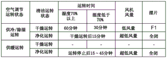
During the drying operation, as shown in fig. 11, the control unit 71 keeps the opening degree of the flap 35 at F1, and causes the fan 18 to operate at a low speed so that the air volume becomes a low air volume.
When the humidity of the room to be conditioned detected by the indoor humidity sensor 75 is 70% or more, the control unit 71 performs the low-speed operation of the fan 18 for 60 minutes. On the other hand, when the humidity of the conditioned room is lower than 70%, the control unit 71 performs the low-speed operation of the fan 18 for 30 minutes. The time of the drying operation is measured by the timer 73 of the control device 70.
As described above, the cooling operation or the drying operation after the dehumidification operation is stopped is performed.
After the drying operation is completed, the control unit 71 performs a purge operation.
During the purge operation, the controller 71 keeps the flap 35 fully closed, and operates the fan 18 at an ultra-low speed, for example, for about 15 minutes, so that the air volume becomes an ultra-low air volume. The time of the purge operation is also measured by the timer 73 of the control device 70.
As described above, the purge operation after the drying operation is performed.
Next, the drying operation and the purging operation after the heating operation is stopped will be described.
In addition, in winter when the heating operation is performed, air is often dried. Therefore, as shown in fig. 11, the drying operation is not performed after the heating operation is stopped, and the purging operation is performed immediately after the heating operation is stopped. However, it is needless to say that the drying operation may be performed as needed.
In the purge operation after the heating operation is stopped, the control unit 71 first completely closes the flap 35. Then, the control unit 71 operates the fan 18 at an ultra-low speed, for example, for about 15 minutes to 45 minutes, so that the air volume becomes an ultra-low air volume.
As described above, the purge operation after the stop of the heating operation is executed.
Next, an operation of the air conditioning operation of the ceiling-embedded indoor unit of the present embodiment will be described.
First, in a case where a normal air conditioning operation is performed, a setting signal from the remote controller 76 or a signal detected by the indoor temperature sensor 74 or humidity sensor 75 is input to the control device 70. The control device 70 controls the drive of the fan motor 23, the flap driving motor 79, the electrostatic atomization device 60, and the like by the control unit 71 based on the input setting signal or the input detection signal.
Thereby, the air in the room to be conditioned is sucked by the fan 18 from the plate-side suction port 31. The sucked air passes through the filter 33 and then is heat-exchanged by the indoor heat exchanger 17 to be air-conditioned. The air-conditioned air is delivered from the plate-side blow-out port 34 to the conditioned room. Then, the above-described operations are continuously executed. Thereby, the air in the conditioned room circulates to perform the air conditioning operation.
Next, a specific control operation of the interior cleaning operation of the ceiling-embedded indoor unit 10 according to the present embodiment will be described with reference to fig. 12.
Fig. 12 is a flowchart showing a control operation of the interior cleaning operation of the ceiling embedded indoor unit 10 according to this embodiment.
As shown in fig. 12, first, the interior cleaning operation is performed from the air conditioning operation (step ST 1).
Next, it is determined whether the air conditioning operation is the cooling operation or the dehumidifying operation (step ST 2).
When the air conditioning operation is the cooling or dehumidifying operation (YES in step ST2), it is determined whether the humidity of the conditioned room is 70% or more or less than 70% (step ST 3).
When the humidity of the chamber to be conditioned is 70% or more (YES in step ST3), the controller 71 controls the damper 35 to be maintained in a slightly opened state (F1 state). Then, the control unit 71 controls the fan motor 23 to rotate at a low rotation speed while maintaining the opening degree of the flap 35, and performs the drying operation for 60 minutes, for example (step ST 4).
On the other hand, when the humidity of the chamber to be conditioned is lower than 70% (NO in step ST3), the controller 71 controls the flap 35 and the fan motor 23 to rotate at a low rotation speed, and performs the drying operation for, for example, 30 minutes (step ST 5).
Next, it is determined whether or not the drying operation for the predetermined time period is finished (step ST 6). At this time, if the drying operation is not completed (NO in step ST6), the control unit 71 continues the drying operation until the predetermined time elapses.
On the other hand, when the drying operation is finished (YES in step ST6), the control unit 71 puts the flap 35 into the fully closed state. The control unit 71 controls the fan 18 to operate at an ultra-low speed so that the air volume becomes an ultra-low air volume. At the same time, the control unit 71 drives the electrostatic atomization device 60 to start the purge operation (step ST 7). As shown in fig. 11, the control unit 71 ends the purge operation when, for example, 15 minutes has elapsed after the start of the purge operation.
On the other hand, in step ST2, when the air conditioning operation is the heating operation (NO in step ST2), the drying operation is not performed, and the controller 71 starts the purge operation (step ST 7). As shown in fig. 11, the control unit 71 ends the purge operation when 45 minutes have elapsed from 15 minutes, for example, after the purge operation is started.
Through the above operations, the control operation of the interior cleaning operation of the ceiling-embedded indoor unit 10 is executed.
As described above, in the ceiling-embedded indoor unit 10 according to the present embodiment, the air inlet 64 of the electrostatic atomizing device 60 that generates mist having a sterilization effect containing charged corpuscle water is provided so as to open in the fan chamber 43 that accommodates the fan 18 in the space surrounded by the indoor heat exchanger 17. The air outlet 63a of the electrostatic atomizing device 60 is provided so as to open in the air blowing path 44. In addition, the ceiling buried indoor unit 10 includes a control device 70 that drive-controls the fan 18, the flap 35, and the electrostatic atomization device 60. The control device 70 controls the fan 18 and the electrostatic atomization device 60 to perform the cleaning operation during the internal cleaning operation.
With this configuration, the controller 70 drives the fan 18 and the electrostatic atomization device 60 to perform the cleaning operation during the interior cleaning operation of the ceiling-embedded indoor unit 10. Thereby, the inside of the casing 15 of the ceiling-embedded indoor unit 10 can be effectively sterilized and deodorized. As a result, the generation of mold, virus, or the like inside the ceiling-embedded indoor unit 10 can be reliably prevented.
In addition, the controller 70 of the ceiling-embedded indoor unit 10 according to the present embodiment drives the fan 18 to perform the drying operation before the cleaning operation is performed during the interior cleaning operation.
Thus, the interior of the casing 15 of the ceiling-embedded indoor unit 10 is dried in advance, and an environment in which mold, virus, or the like is less likely to occur is realized. As a result, the interior of the ceiling-embedded indoor unit 10 can be sterilized more efficiently.
Further, the control device 70 of the ceiling-embedded indoor unit 10 according to the present embodiment controls the swing piece 35 to be closed or the swing piece 35 to be slightly opened during the interior cleaning operation.
Thus, the ceiling-embedded indoor unit 10 can efficiently suck the mist with the sterilization function discharged from the electrostatic atomization device 60 into the room to be conditioned, from the plate-side suction port 31. As a result, the interior of the ceiling-embedded indoor unit 10 can be sterilized and deodorized more efficiently.
The flap 35 of the ceiling-embedded indoor unit 10 according to the present embodiment includes the 1 st guide plate 37 and the 2 nd guide plate 38, and the 1 st guide plate 37 and the 2 nd guide plate 38 are coupled by a coupling member to form a gap through which air passes.
According to this configuration, the air sent to the plate-side outlet 34 (outlet) can be discharged from the gap between the 1 st guide plate 37 and the 2 nd guide plate 38. Thus, even in the state where the flap 35 is closed, the air discharged from the discharge port can be sucked from the plate-side suction port 31.
The present invention is described based on the above embodiments, but the present invention is not limited to the embodiments. The above embodiment exemplifies one embodiment of the present invention, and therefore, any modification and application can be made without departing from the spirit of the present invention.
Claims (3)
1. A ceiling flush indoor unit, comprising:
a casing having a panel-side suction port for sucking air in the room to be conditioned and a panel-side blow-out port for blowing out air into the room to be conditioned;
a swing piece provided at the board-side air outlet;
a fan disposed within the housing;
an electrostatic atomization device for generating a sterilization mist containing charged corpuscle water and releasing the sterilization mist into the housing;
a control device for drive-controlling the fan, the flap, and the electrostatic atomization device, wherein
The air sucked from the suction passage at the center of the drain pan is heat-exchanged by the indoor heat exchanger and blown out from the plate-side blow-out port through the blow-out passage downstream of the indoor heat exchanger,
the control means controls the flap to be in a closed or slightly open state during the internal cleaning operation, and controls to perform a cleaning operation of driving the fan and the electrostatic atomization device,
the blade includes a 1 st guide plate and a 2 nd guide plate, the 1 st guide plate and the 2 nd guide plate are coupled by a coupling member, and a gap through which air passes is formed between the 1 st guide plate and the 2 nd guide plate.
2. The ceiling flush indoor unit of claim 1, wherein:
further comprising an indoor heat exchanger surrounding the fan,
the air inlet of the electrostatic atomizer is a space surrounded by the indoor heat exchanger and is open to a fan chamber for housing the fan, and the air outlet of the electrostatic atomizer is provided to open to an air passage formed downstream of the indoor heat exchanger.
3. The ceiling flush indoor unit of claim 1 or 2, wherein:
the control device performs a drying operation for driving the fan before performing the cleaning operation during an internal cleaning operation.
Applications Claiming Priority (2)
| Application Number | Priority Date | Filing Date | Title |
|---|---|---|---|
| JP2016005324A JP6611006B2 (en) | 2016-01-14 | 2016-01-14 | Recessed ceiling indoor unit |
| JP2016-005324 | 2016-01-14 |
Publications (2)
| Publication Number | Publication Date |
|---|---|
| CN106969410A CN106969410A (en) | 2017-07-21 |
| CN106969410B true CN106969410B (en) | 2021-03-09 |
Family
ID=59335235
Family Applications (1)
| Application Number | Title | Priority Date | Filing Date |
|---|---|---|---|
| CN201610685262.5A Active CN106969410B (en) | 2016-01-14 | 2016-08-18 | Ceiling-embedded indoor unit |
Country Status (2)
| Country | Link |
|---|---|
| JP (1) | JP6611006B2 (en) |
| CN (1) | CN106969410B (en) |
Families Citing this family (9)
| Publication number | Priority date | Publication date | Assignee | Title |
|---|---|---|---|---|
| JP7185392B2 (en) * | 2017-08-10 | 2022-12-07 | ダイキン工業株式会社 | Indoor unit of air conditioner |
| JP6755409B2 (en) * | 2017-10-18 | 2020-09-16 | 三菱電機株式会社 | Indoor unit of air conditioner |
| KR102043661B1 (en) * | 2018-03-13 | 2019-11-12 | 엘지전자 주식회사 | Ceiling type air conditioner |
| CN111442409A (en) * | 2019-01-17 | 2020-07-24 | 青岛海尔空调器有限总公司 | Air conditioner |
| JP7300621B2 (en) * | 2019-02-20 | 2023-06-30 | パナソニックIpマネジメント株式会社 | air conditioner |
| CN112128928A (en) * | 2019-06-25 | 2020-12-25 | 青岛海尔空调器有限总公司 | Air conditioner and cleaning and sterilizing method thereof |
| CN112432318B (en) * | 2019-08-26 | 2022-04-12 | 广东美的制冷设备有限公司 | Air purification assembly, control method and device thereof, air conditioner and storage medium |
| JP7193750B2 (en) * | 2021-03-12 | 2022-12-21 | ダイキン工業株式会社 | air conditioner |
| JP2023049970A (en) * | 2021-09-29 | 2023-04-10 | パナソニックIpマネジメント株式会社 | indoor unit |
Citations (11)
| Publication number | Priority date | Publication date | Assignee | Title |
|---|---|---|---|---|
| CN2442145Y (en) * | 1999-10-29 | 2001-08-08 | 大金工业株式会社 | Indoor machine of air conditioner |
| JP2001324194A (en) * | 2000-05-18 | 2001-11-22 | Matsushita Refrig Co Ltd | Air conditioner |
| CN1403748A (en) * | 2001-08-28 | 2003-03-19 | 东芝开利株式会社 | Air conditioner |
| CN2627393Y (en) * | 2003-06-06 | 2004-07-21 | 珠海格力电器股份有限公司 | Air-conditioner with ultraviolet light degerming device |
| CN101158491A (en) * | 2006-08-25 | 2008-04-09 | 三洋电机株式会社 | Indoor unit of air conditioning apparatus, air conditioning apparatus and control method thereof |
| JP2010159910A (en) * | 2009-01-08 | 2010-07-22 | Sanyo Electric Co Ltd | Ceiling-embedded air conditioner |
| CN101828077A (en) * | 2007-10-16 | 2010-09-08 | 松下电器产业株式会社 | Air conditioning apparatus |
| CN101903706A (en) * | 2007-12-21 | 2010-12-01 | 松下电器产业株式会社 | Air conditioner |
| CN103557561A (en) * | 2008-12-15 | 2014-02-05 | 大金工业株式会社 | Air conditioning indoor unit embedded in ceiling |
| CN104676759A (en) * | 2015-02-13 | 2015-06-03 | 广东美的制冷设备有限公司 | Air conditioner indoor unit and control method thereof |
| CN204555015U (en) * | 2015-02-13 | 2015-08-12 | 广东美的制冷设备有限公司 | Air conditioner room unit and deep bead |
-
2016
- 2016-01-14 JP JP2016005324A patent/JP6611006B2/en active Active
- 2016-08-18 CN CN201610685262.5A patent/CN106969410B/en active Active
Patent Citations (11)
| Publication number | Priority date | Publication date | Assignee | Title |
|---|---|---|---|---|
| CN2442145Y (en) * | 1999-10-29 | 2001-08-08 | 大金工业株式会社 | Indoor machine of air conditioner |
| JP2001324194A (en) * | 2000-05-18 | 2001-11-22 | Matsushita Refrig Co Ltd | Air conditioner |
| CN1403748A (en) * | 2001-08-28 | 2003-03-19 | 东芝开利株式会社 | Air conditioner |
| CN2627393Y (en) * | 2003-06-06 | 2004-07-21 | 珠海格力电器股份有限公司 | Air-conditioner with ultraviolet light degerming device |
| CN101158491A (en) * | 2006-08-25 | 2008-04-09 | 三洋电机株式会社 | Indoor unit of air conditioning apparatus, air conditioning apparatus and control method thereof |
| CN101828077A (en) * | 2007-10-16 | 2010-09-08 | 松下电器产业株式会社 | Air conditioning apparatus |
| CN101903706A (en) * | 2007-12-21 | 2010-12-01 | 松下电器产业株式会社 | Air conditioner |
| CN103557561A (en) * | 2008-12-15 | 2014-02-05 | 大金工业株式会社 | Air conditioning indoor unit embedded in ceiling |
| JP2010159910A (en) * | 2009-01-08 | 2010-07-22 | Sanyo Electric Co Ltd | Ceiling-embedded air conditioner |
| CN104676759A (en) * | 2015-02-13 | 2015-06-03 | 广东美的制冷设备有限公司 | Air conditioner indoor unit and control method thereof |
| CN204555015U (en) * | 2015-02-13 | 2015-08-12 | 广东美的制冷设备有限公司 | Air conditioner room unit and deep bead |
Also Published As
| Publication number | Publication date |
|---|---|
| JP2017125652A (en) | 2017-07-20 |
| CN106969410A (en) | 2017-07-21 |
| JP6611006B2 (en) | 2019-11-27 |
Similar Documents
| Publication | Publication Date | Title |
|---|---|---|
| CN106969410B (en) | Ceiling-embedded indoor unit | |
| JP2019501358A (en) | Air cleaner | |
| WO2011030602A1 (en) | Air conditioner | |
| KR101837621B1 (en) | Air conditioner | |
| JP2018004122A (en) | Humidifier | |
| JP6579517B2 (en) | Recessed ceiling indoor unit | |
| JP2017072320A (en) | Blower module | |
| CN106949536B (en) | Ceiling-embedded indoor unit | |
| JP2004293893A (en) | Air conditioner | |
| JP2011058725A (en) | Air conditioner | |
| JP2014217810A (en) | Mist generating device | |
| JP6475602B2 (en) | Humidifier | |
| KR101555199B1 (en) | air conditioner | |
| KR20160036467A (en) | Electric Heater Bathroom Ceiling Combination Ventilating Fan | |
| JP4617739B2 (en) | Air cleaner | |
| JP6442862B2 (en) | Blower | |
| JP2014035089A (en) | Air conditioner | |
| JP7150493B2 (en) | air conditioner | |
| JP3789807B2 (en) | Bathroom heater | |
| JP2011147687A (en) | Laundry drying system and blower | |
| JP2015183982A (en) | Ventilation device | |
| JP2005164213A (en) | Ceiling suspension type air conditioner | |
| JP2002089878A (en) | Air conditioner | |
| JP2012097999A (en) | Air conditioner | |
| WO2021075399A1 (en) | Air purifier |
Legal Events
| Date | Code | Title | Description |
|---|---|---|---|
| PB01 | Publication | ||
| SE01 | Entry into force of request for substantive examination | ||
| SE01 | Entry into force of request for substantive examination | ||
| GR01 | Patent grant | ||
| GR01 | Patent grant |