CN106948671B - Intelligent case fingerprint electronic lock - Google Patents
Intelligent case fingerprint electronic lock Download PDFInfo
- Publication number
- CN106948671B CN106948671B CN201710161628.3A CN201710161628A CN106948671B CN 106948671 B CN106948671 B CN 106948671B CN 201710161628 A CN201710161628 A CN 201710161628A CN 106948671 B CN106948671 B CN 106948671B
- Authority
- CN
- China
- Prior art keywords
- lock
- motor
- fingerprint
- push rod
- base
- Prior art date
- Legal status (The legal status is an assumption and is not a legal conclusion. Google has not performed a legal analysis and makes no representation as to the accuracy of the status listed.)
- Active
Links
Images


Classifications
-
- E—FIXED CONSTRUCTIONS
- E05—LOCKS; KEYS; WINDOW OR DOOR FITTINGS; SAFES
- E05B—LOCKS; ACCESSORIES THEREFOR; HANDCUFFS
- E05B49/00—Electric permutation locks; Circuits therefor ; Mechanical aspects of electronic locks; Mechanical keys therefor
-
- E—FIXED CONSTRUCTIONS
- E05—LOCKS; KEYS; WINDOW OR DOOR FITTINGS; SAFES
- E05B—LOCKS; ACCESSORIES THEREFOR; HANDCUFFS
- E05B47/00—Operating or controlling locks or other fastening devices by electric or magnetic means
- E05B47/0001—Operating or controlling locks or other fastening devices by electric or magnetic means with electric actuators; Constructional features thereof
- E05B47/0012—Operating or controlling locks or other fastening devices by electric or magnetic means with electric actuators; Constructional features thereof with rotary electromotors
-
- E—FIXED CONSTRUCTIONS
- E05—LOCKS; KEYS; WINDOW OR DOOR FITTINGS; SAFES
- E05B—LOCKS; ACCESSORIES THEREFOR; HANDCUFFS
- E05B65/00—Locks or fastenings for special use
- E05B65/52—Other locks for chests, boxes, trunks, baskets, travelling bags, or the like
-
- E—FIXED CONSTRUCTIONS
- E05—LOCKS; KEYS; WINDOW OR DOOR FITTINGS; SAFES
- E05B—LOCKS; ACCESSORIES THEREFOR; HANDCUFFS
- E05B47/00—Operating or controlling locks or other fastening devices by electric or magnetic means
- E05B47/0001—Operating or controlling locks or other fastening devices by electric or magnetic means with electric actuators; Constructional features thereof
- E05B2047/0014—Constructional features of actuators or power transmissions therefor
- E05B2047/0018—Details of actuator transmissions
- E05B2047/0024—Cams
Landscapes
- Lock And Its Accessories (AREA)
Abstract
An intelligent luggage fingerprint electronic lock comprises a lock base (1) and a lock catch seat (19) which are respectively fixed on a box body and a box cover, wherein a lock catch (17) provided with an unlocking return spring (18) is hinged on the lock catch seat, two protruding buckle columns are arranged on the lock catch, a lock hole is formed in each buckle column, a buckle hole is formed in the position, corresponding to the corresponding buckle column, of the lock base, a lock clamp (5) capable of stretching into the lock hole to clamp the lock hole to lock and quit unlocking is arranged corresponding to the lock hole, and a reset locking spring (12) is arranged on each lock clamp; the lock base in be equipped with motor (9) actuating mechanism and connect the lock card, the hasp seat on be equipped with the public head of POGOPIN, be equipped with the female head of POGOPIN on the lock base, the female head electricity of POGOPIN is connected the motor, the public first electricity of POGOPIN connect the electron fingerprint lock of establishing the battery on the case lid. The invention adopts the fingerprint lock, the unlocking is convenient and quick, and the worry of forgetting the password is avoided; the mode that the motor rotates to drive the axial cam to loosen the lock clamp and unlock the lock through the manual key is adopted, and the power consumption of the battery is greatly saved.
Description
Technical Field
The invention relates to a case lock, in particular to an intelligent case fingerprint electronic lock.
Background
The case lock of the existing draw-bar case is mostly a coded lock, one side of the case body of the draw-bar case is hinged with the case cover, and the other side of the case body is buckled with the case lock. A commonly used combination lock structure includes: fix lock base 1 and hasp seat 19 on box and case lid respectively, it has hasp 17 to articulate on the hasp seat, has two outstanding posts of buckleing on the hasp, and it has the lockhole to open on the post to buckle, opens corresponding to buckleing the post position on the lock base and has the button hole, is equipped with the lock card 5 that can stretch into to withdraw from corresponding to the lockhole, and its structure is: the lock is horizontally placed, two ends of the lock are bent in the same direction and are in a channel steel shape, protruding button hole clamping blocks are arranged on the rear sides of the two right-angled bent ends, and a reset locking spring 12 is arranged on the front side of one right-angled bent end and is pressed against the lock base 1; the button hole clamping block of the lock clamp 5 extends into the lock hole to lock and withdraw to unlock, and the lock clamp 5 is in a locked state when flat; three other coded gear mechanisms lock the lock card 5. When the three password gear mechanisms are rotated to lock the password, the unlocking card 5 can be sent to unlock.
The coded lock has the following defects: firstly, the unlocking is not convenient, the time is long, and particularly, because the code wheel of the code lock is small, the number on the code lock is smaller, and the old people cannot easily see the code lock clearly; the most important is that the case is generally used when going on a business trip, traveling or going home, so the password is easy to forget, and only the case body can be broken.
Also have case and bag electronic lock on the market, but its design is not good, and electronic unblanking and shutting are big, and the power consumption can appear the awkward condition sometimes: when the luggage needs to be opened during traveling, the battery is not charged and can not be opened, and particularly if the situation occurs when the luggage passes customs and is subjected to side inspection, the battery is converged to bring bad experience to users.
Disclosure of Invention
The invention aims to solve the technical problem of providing an intelligent luggage fingerprint electronic lock which is convenient and quick to unlock, has no worry of forgetting a password and is very power-saving.
To solve the technical problems, the invention adopts the following technical scheme:
an intelligent case fingerprint electronic lock comprises a lock base 1 and a lock catch base 19 which are respectively fixed on a case body and a case cover, wherein a lock catch 17 provided with an unlocking reset spring 18 is hinged on the lock catch base 19, two protruded buckling columns are arranged on the lock catch 17, lock holes are formed in the buckling columns, buckling holes are formed in the lock base 1 corresponding to the buckling columns, a lock clamp 5 which can stretch into the locking lock holes to lock and withdraw from unlocking is arranged corresponding to the lock holes, and a reset locking spring 12 is arranged on the lock clamp 5; the method is characterized in that: lock base 1 in be equipped with motor 9 actuating mechanism and connect lock card 5, hasp seat 19 on be equipped with the public head of POGOPIN, be equipped with the female head of POGOPIN on the lock base 1, the female head electricity of POGOPIN is connected motor 9, the public first electricity of POGOPIN connect the electron fingerprint lock of establishing the battery on the case lid.
The structure that motor drive mechanism connects latch 5 include: the output shaft of the motor 9 is fixedly provided with a motor cam 8, the cam 8 is in contact connection with a motor push rod 7, the motor push rod 7 is in contact connection with a limiting rotor 6, the limiting rotor 6 is provided with a return rotor spring 11 for limiting the back and forth movement of a push rod 4, and the push rod 4 is connected with an unlocking button 3 and is simultaneously connected with the lock clamp 5.
The working principle and the process are as follows: the lock catch seat 19 and the lock base 1 are locked together through a lock catch 17, and the motor is connected with the electronic fingerprint lock through a lead 16 of the lock base 1, namely a lead 14, a POGOPIN female head, a POGOPIN male head and the lock catch seat 19. When the fingerprint identification is successful, the motor rotates to drive the motor cam to rotate to the highest point, the motor push rod is pushed, the limiting rotor is pushed to rotate, the releasing position is given to the push rod (which is propped up before), then the unlocking button is manually pressed, the push rod is pushed, the lock catch is pushed to withdraw, the lock catch is released, and the lock catch springs to be opened, so that the unlocking is completed.
When the lock catch seat and the lock base are separated, and the lock catch seat and the lock base are closed through the button hole guide groove, the POGOPIN female head is communicated with the POGOPIN male head, the motor rotates to drive the motor cam to rotate to the lowest point, the motor push rod retracts through the rotor spring, the limiting rotor rotates through the rotor spring, the push rod is blocked, and the unlocking button cannot be pressed manually to complete locking.
Preferably, the motor cam 8 is a cam with different axial thicknesses, the limiting rotor 6 provided with the return rotor spring 11 is a rotary column with a rotary axis perpendicular to the motion direction of the push rod 7, two baffle plates which form a right angle with each other radially extend out of the rotary column, the front of one baffle plate corresponds to the motor push rod 7, the back of the baffle plate is provided with the return rotor spring 11 and abuts against the lock base 1, the other baffle plate corresponds to the moving direction of the push rod 4 and abuts against the front end of the push rod 4, the rear end of the push rod 4 abuts against the front end of the unlocking button 3, the top surface of the rear part of the push rod 4 is provided with a bulge, and the bulge abuts against the rear end of the lock clamp 5.
The electronic fingerprint lock includes:
a long rectangular box with panel 23, embedded main part support 28, inside battery 26, fingerprint module 25 and the mainboard 29 of being equipped with of main part support 28, fingerprint module 25 electricity connection mainboard 29, battery 26 and motor 6 in proper order.
The long rectangular box body is also internally provided with a fingerprint input elimination key 30 which is connected with the main board, and the fingerprint input elimination key 30 is exposed on the end surface of the box body.
The panel 23 is provided with three openings, one opening is hinged with the cover plate 21, the other opening exposes the fingerprint module 25, the other opening exposes an interface board 24 fixed on the main body bracket, and the interface board 24 is provided with an external power supply charging port connected with the main board and the battery; a door lock switch 22 is provided on the bottom surface of the cover plate 21 and the corresponding panel.
On the basis of the above, the invention can be further improved:
add a customs TSA lock, which includes: and a lock cylinder baffle extending out in the radial direction is also arranged on the rotary column of the limiting rotor 6 and corresponds to a shifting block of the customs lock cylinder 10.
The customs TSA lock 10 is rotated through the customs TSA key, the limiting rotor is rotated, the push rod is loosened for limiting, the unlocking key is pressed, the push rod is pushed, the lock catch is loosened, and the lock catch is bounced through the lock catch spring to unlock the lock.
Compared with the prior art, the invention has the following beneficial effects:
the invention adopts the fingerprint lock, the unlocking is convenient and quick, and the worry of forgetting the password is avoided; the mode that the motor rotates to drive the axial cam to loosen the lock clamp and the manual key is used for unlocking is adopted, and the power consumption of the battery is greatly saved.
Drawings
FIG. 1 is one of the schematic illustrations of the embodiment of the present invention mounted on a draw-bar case (unlocked);
FIG. 2 is a second schematic illustration of the embodiment of the invention mounted on a trolley case (latch);
FIG. 3 is one of the schematic illustrations of the shackle seat and the lock base separated (assembled front face) of an embodiment of the present invention;
FIG. 4 is a second schematic illustration of the separation of the shackle seat and the lock base (reverse side disassembled) of the embodiment of the present invention;
FIG. 5 is one of the schematic views (the reverse side disassembled) of the shackle seat and lock base combination lock of the present invention;
FIG. 6 is one of the schematic views (assembled front side) of the shackle seat and lock base combination lock of the present invention;
FIG. 7 is an exploded view of the shackle seat and the lock base of an embodiment of the present invention separated;
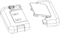
FIG. 8 is an exploded view (front) of the electronic fingerprint lock with a battery mounted on the lid;
FIG. 9 is a second (reverse) schematic diagram of an electronic fingerprint lock with a battery mounted on the case lid;
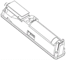
FIG. 10 is one of the assembled (non-covered reverse side) schematic views of the electronic fingerprint lock with a battery mounted on the cover;
FIG. 11 is a second schematic view of the assembled (uncovered front) electronic fingerprint lock with a battery on the cover;
FIG. 12 is an assembled schematic view of an electronic fingerprint lock with a battery mounted on the case lid;
fig. 13 is a schematic view of the installation position of the fingerprint input elimination key of the electronic fingerprint lock.
In the figure: 1-lock base, 2-lock base cover plate, 3-unlock key, 4-push rod, 5-lock clip, 6-limit rotor, 7-motor push rod, 8-motor cam, 9-motor, 10-customs lock core, 11-rotor spring, 12-lock clip spring, 13-POGOPIN female head, 14-lock base lead, 15-POGOPIN male head, 16-lock base lead, 17-lock catch, 18-lock catch spring, 19-lock catch base, 20-lock base cover plate; 21-fingerprint lock cover plate, 22-door lock switch, 23-fingerprint lock panel, 24-interface board, 25-fingerprint module, 26-battery, 27-battery shrapnel, 28-main body bracket, 29-main board, 30-fingerprint input elimination key, 31-bluetooth board, 32-bottom cover, 33-panel key, 34-indicator lamp lens and 35-cover plate spring.
Detailed Description
The invention will now be further illustrated by the following examples in conjunction with the accompanying drawings.
Referring to fig. 1 to 12, the embodiment of the fingerprint electronic lock for the intelligent case comprises a lock base 1 and a lock catch base 19 which are respectively fixed on a case body and a case cover, wherein a lock catch 17 provided with an unlocking return spring 18 is hinged on the lock catch base 19, two protruding lock posts are arranged on the lock catch 17, and a lock hole is formed in each lock post. The lock base 1 is provided with a button hole (or a guide groove) corresponding to the button column, and a lock clamp 5 which can extend into the lock hole to clamp the lock hole and lock and withdraw from unlocking is arranged corresponding to the lock hole.
Referring to fig. 7, the latch 5 has the following structure: the lock is horizontally placed, two ends of the lock are bent in the same direction and are in a channel steel shape, protruding button hole clamping blocks are arranged on the rear sides of the two right-angled bent ends, and a reset locking spring 12 is arranged on the front side of the right-angled bent end behind the position and is pressed against the lock base 1; the button hole clamping block of the locking clamp 5 moves backwards and extends into the lock hole to lock, and moves forwards and exits from the lock hole to unlock. Due to the spring 12, the lock catch 5 is normally in a locked state. See fig. 1-7.
Be equipped with motor 9 actuating mechanism in the lock base 1 and connect lock card 5, be equipped with the public head 15 of POGOPIN on the hasp seat 19, be equipped with the female head 13 of POGOPIN on the lock base 1, the female head 13 of POGOPIN passes through 14 electricity connection direct current miniature gear motor 9 of wire, and the public head of POGOPIN passes through 16 electricity connections and establishes the mainboard that is equipped with the electron fingerprint lock of battery on the case lid.
The structure that specific motor 9 actuating mechanism connects latch 5 includes: the output shaft of the motor 9 is fixed with a motor cam 8, the cam 8 is in contact connection with a motor push rod 7, the motor push rod 7 is in contact connection with a limiting rotor 6, the limiting rotor 6 is provided with a return rotor spring 11 and limits the forward movement of a push rod 4, and the push rod 4 is connected with an unlocking button 3 and is simultaneously connected with a lock clamp 5.
The motor cam 8 is the cam that the axial thickness is different, the spacing rotor 6 that is equipped with return rotor spring 11 is the rotary column of gyration axis perpendicular to push rod 7 and 4 direction of motion of push rod, radially stretch out two fenders of mutually orthogonal on the rotary column, the preceding motor push rod 7 that corresponds of a baffle, it pushes up on locking base 1 to be equipped with return rotor spring 11 at the back, another baffle is just corresponding push rod 4 antedisplacement direction and is pushing up push rod 4 front end, the rear end top of push rod 4 is at the 3 front ends of key of unblanking, the top surface at the rear portion of push rod 4 is equipped with the arch, the arch top is at 5 rear ends of locking card.
Of course, the cam 8 can be directly pressed against the baffle of the limit rotor 6, and the push rod 4, the unlocking button 3 and the lock clip 5 can be designed into a whole.
Referring to fig. 7, a customs TSA lock is added to the lock base, which includes: and a lock cylinder baffle extending out in the radial direction is also arranged on the rotary column of the limiting rotor 6 and corresponds to a shifting block of the customs lock cylinder 10. The customs TSA lock 10 is rotated through the customs TSA key, the limiting rotor is rotated, the push rod is loosened for limiting, the unlocking key is pressed, the push rod is pushed, the lock catch is loosened, and the lock catch is bounced through the lock catch spring to unlock the lock.
Referring to fig. 8 to 12, the electronic fingerprint lock includes: a long rectangular box with panel 23, embedded main part support 28, inside battery 26, fingerprint module 25 and the mainboard 29 of being equipped with of main part support 28, fingerprint module 25 electricity connection mainboard 29, battery 26 and motor 6 in proper order.
The main board 29 receives the fingerprint transmitted by the fingerprint module 25 and verifies the fingerprint, and if the fingerprint is correct, the main board controls the battery to be conducted to supply power to the motor 6.
The fingerprint lock panel 23 is provided with three openings, one opening is hinged with a fingerprint lock cover plate 21 provided with a cover plate spring 35, the other opening exposes the fingerprint module 25, the other opening exposes an interface plate 24 fixed on the main body bracket, and the interface plate 24 is provided with an external power supply charging port connected with a mainboard and a battery; a door lock switch 22 is provided on the bottom surface of the cover plate 21 and the corresponding panel.
Referring to fig. 13, a fingerprint inputting and eliminating button 30 is further arranged in the long rectangular box body and connected with the main board, and the fingerprint inputting and eliminating button 30 is exposed on the end face of the box body and used for inputting or eliminating fingerprints capable of being unlocked.
Two openings are arranged on the panel 23, one opening is hinged with a cover plate 21, the other opening is exposed out of the fingerprint module 25, and a door lock switch 22 is arranged on the bottom surface of the cover plate 21 and the corresponding panel.
The embodiment is also provided with a Bluetooth switch 33 connected with the Bluetooth plate 31 for anti-theft.
Claims (3)
1. An intelligent case fingerprint electronic lock comprises a lock base (1) and a lock catch seat (19) which are respectively fixed on a case body and a case cover, wherein a lock catch (17) provided with an unlocking reset spring (18) is hinged on the lock catch seat, two protruding lock posts are arranged on the lock catch, a lock hole is formed in each lock post, a lock hole is formed in the lock base corresponding to the position of each lock post, a lock clip (5) capable of stretching into and blocking the lock hole to lock and quit unlocking is arranged corresponding to the lock hole, and a reset locking spring (12) is arranged in each lock clip; a motor (9) driving mechanism is arranged in the lock base and connected with the lock clamp, a POGOPIN male head is arranged on the lock base, a POGOPIN female head is arranged on the lock base and electrically connected with the motor, and the POGOPIN male head is electrically connected with an electronic fingerprint lock provided with a battery on a box cover;
the structure that motor drive mechanism connects latch (5) include: a motor cam (8) is fixed on an output shaft of the motor (9), the cam is in contact connection with a motor push rod (7), the motor push rod is in contact connection with a limiting rotor (6), the limiting rotor is provided with a return rotor spring (11) to limit the back and forth movement of a push rod (4), and the push rod is connected with an unlocking button (3) and is simultaneously connected with the lock clip;
the motor cam (8) is a cam with different axial thicknesses, the limiting rotor (6) provided with a return rotor spring (11) is a rotating column with a rotating axis perpendicular to the moving direction of the motor push rod (7), two baffle plates which form a right angle with each other radially extend out of the rotating column, the front of one baffle plate corresponds to the motor push rod, the back of the other baffle plate corresponds to the moving direction of the push rod (4) and pushes the front end of the push rod (4), the rear end of the push rod (4) pushes the front end of the unlocking key (3), the top surface of the rear part of the push rod (4) is provided with a bulge, and the bulge pushes the rear end of the locking clamp (5);
the electronic fingerprint lock includes: the fingerprint identification device comprises a long rectangular box body with a panel (23), a main body support (28) is embedded in the long rectangular box body, a battery (26), a fingerprint module (25) and a main board (29) are arranged in the main body support (28), and the fingerprint module (25) is electrically connected with the main board (29), the battery (26) and a motor (6) in sequence;
and a lock cylinder baffle extending out in the radial direction is also arranged on the rotary column of the limiting rotor (6) and corresponds to a shifting block of the customs lock cylinder (10).
2. The intelligent case fingerprint electronic lock of claim 1, wherein: the long rectangular box body is also internally provided with a fingerprint input elimination key (30) connected with the main board, and the fingerprint input elimination key (30) is exposed on the end surface of the box body.
3. The intelligent case fingerprint electronic lock of claim 2, wherein: the panel (23) is provided with three openings, one opening is hinged with a cover plate (21), the other opening exposes the fingerprint module (25), the other opening exposes an interface board (24) fixed on the main body bracket, and the interface board (24) is provided with an external power supply charging port connected with the main board and the battery; a door lock switch (22) is arranged on the bottom surface of the cover plate (21) and the corresponding panel.
Priority Applications (1)
| Application Number | Priority Date | Filing Date | Title |
|---|---|---|---|
| CN201710161628.3A CN106948671B (en) | 2017-03-17 | 2017-03-17 | Intelligent case fingerprint electronic lock |
Applications Claiming Priority (1)
| Application Number | Priority Date | Filing Date | Title |
|---|---|---|---|
| CN201710161628.3A CN106948671B (en) | 2017-03-17 | 2017-03-17 | Intelligent case fingerprint electronic lock |
Publications (2)
| Publication Number | Publication Date |
|---|---|
| CN106948671A CN106948671A (en) | 2017-07-14 |
| CN106948671B true CN106948671B (en) | 2022-08-05 |
Family
ID=59472767
Family Applications (1)
| Application Number | Title | Priority Date | Filing Date |
|---|---|---|---|
| CN201710161628.3A Active CN106948671B (en) | 2017-03-17 | 2017-03-17 | Intelligent case fingerprint electronic lock |
Country Status (1)
| Country | Link |
|---|---|
| CN (1) | CN106948671B (en) |
Families Citing this family (5)
| Publication number | Priority date | Publication date | Assignee | Title |
|---|---|---|---|---|
| CN107489313B (en) * | 2017-08-09 | 2022-07-05 | 罗菊芳 | Intelligent electronic lock for luggage |
| CN107481365A (en) * | 2017-08-09 | 2017-12-15 | 罗菊芳 | A kind of electronic fingerprint device of intelligent case electronic lock |
| CN107893585B (en) * | 2017-11-30 | 2023-09-26 | 东莞市怡丰锁业有限公司 | Intelligent lock for luggage |
| CN112092772A (en) * | 2020-10-16 | 2020-12-18 | 温州市钦点锁业科技有限公司 | Fingerprint-unlocked vehicle-mounted luggage box and control method thereof |
| CN115613906B (en) * | 2022-11-30 | 2023-04-14 | 广东金朋科技有限公司 | Intelligent lock |
Citations (6)
| Publication number | Priority date | Publication date | Assignee | Title |
|---|---|---|---|---|
| CN101033670A (en) * | 2007-04-03 | 2007-09-12 | 金华银 | Fingerprint zipper lock of trunk |
| CN201661142U (en) * | 2010-04-09 | 2010-12-01 | 初昊阳 | Fingerprint lock for cases and bags |
| CN201687288U (en) * | 2010-04-27 | 2010-12-29 | 嘉兴市福布森生物识别技术有限公司 | Fingerprint lock for briefcase |
| CN205224873U (en) * | 2015-11-17 | 2016-05-11 | 竞泰股份有限公司 | Lock set |
| CN205476971U (en) * | 2016-02-05 | 2016-08-17 | 李宗锦 | Case and bag fingerprint lock |
| CN208056868U (en) * | 2017-03-17 | 2018-11-06 | 罗菊芳 | A kind of intelligence luggage fingerprint electronic lock |
-
2017
- 2017-03-17 CN CN201710161628.3A patent/CN106948671B/en active Active
Patent Citations (6)
| Publication number | Priority date | Publication date | Assignee | Title |
|---|---|---|---|---|
| CN101033670A (en) * | 2007-04-03 | 2007-09-12 | 金华银 | Fingerprint zipper lock of trunk |
| CN201661142U (en) * | 2010-04-09 | 2010-12-01 | 初昊阳 | Fingerprint lock for cases and bags |
| CN201687288U (en) * | 2010-04-27 | 2010-12-29 | 嘉兴市福布森生物识别技术有限公司 | Fingerprint lock for briefcase |
| CN205224873U (en) * | 2015-11-17 | 2016-05-11 | 竞泰股份有限公司 | Lock set |
| CN205476971U (en) * | 2016-02-05 | 2016-08-17 | 李宗锦 | Case and bag fingerprint lock |
| CN208056868U (en) * | 2017-03-17 | 2018-11-06 | 罗菊芳 | A kind of intelligence luggage fingerprint electronic lock |
Also Published As
| Publication number | Publication date |
|---|---|
| CN106948671A (en) | 2017-07-14 |
Similar Documents
| Publication | Publication Date | Title |
|---|---|---|
| CN106948671B (en) | Intelligent case fingerprint electronic lock | |
| CN104034203B (en) | Gun intelligent safety lock | |
| CN108590377B (en) | Bluetooth intelligent padlock | |
| EP2255052A1 (en) | Micro motor locking system | |
| CN109610955B (en) | Fingerprint padlock | |
| CN206053588U (en) | A kind of safety magnetic card lock | |
| CN108851419A (en) | Luggage case with built-in electronic lock | |
| CN202152570U (en) | Highly-safe coded lock with high safety | |
| CN208056868U (en) | A kind of intelligence luggage fingerprint electronic lock | |
| WO2020093941A1 (en) | Mechanical lock unlocking apparatus and mounting method therefor | |
| CN108974189B (en) | Locking mechanism and locking pile | |
| CN110029884B (en) | Intelligent case lock | |
| CN108166844A (en) | Thumb wheel component and linkage lock core | |
| CN201486279U (en) | Saddle lock | |
| CN212890523U (en) | Supermarket handcart hasp subassembly | |
| CN209691668U (en) | A kind of motorcycle or electronic automobile-used mechanical, electronics dual-purpose multifunctional combine ignition switch | |
| CN208371136U (en) | Has the luggage case of built-in lock construction | |
| CN210622517U (en) | Self-powered intelligent lock | |
| CN104034202A (en) | Smart safety lock for guns | |
| CN201071638Y (en) | Electronic door lock body | |
| CN211081360U (en) | Passive idling electronic lock | |
| CN207609264U (en) | Thumb wheel component and linkage lock core | |
| CN208198649U (en) | A kind of scooter, beam bending bicycle or the automobile-used multifunctional combination ignition switch of storage battery | |
| CN202125129U (en) | Lock core device of idle mortise type electric lock | |
| CN107489313B (en) | Intelligent electronic lock for luggage |
Legal Events
| Date | Code | Title | Description |
|---|---|---|---|
| PB01 | Publication | ||
| PB01 | Publication | ||
| SE01 | Entry into force of request for substantive examination | ||
| SE01 | Entry into force of request for substantive examination | ||
| GR01 | Patent grant | ||
| GR01 | Patent grant |