CN106936007B - Card edge connector - Google Patents
Card edge connector Download PDFInfo
- Publication number
- CN106936007B CN106936007B CN201710196913.9A CN201710196913A CN106936007B CN 106936007 B CN106936007 B CN 106936007B CN 201710196913 A CN201710196913 A CN 201710196913A CN 106936007 B CN106936007 B CN 106936007B
- Authority
- CN
- China
- Prior art keywords
- card edge
- edge connector
- long
- wall
- walls
- Prior art date
- Legal status (The legal status is an assumption and is not a legal conclusion. Google has not performed a legal analysis and makes no representation as to the accuracy of the status listed.)
- Active
Links
Images


Classifications
-
- H—ELECTRICITY
- H01—ELECTRIC ELEMENTS
- H01R—ELECTRICALLY-CONDUCTIVE CONNECTIONS; STRUCTURAL ASSOCIATIONS OF A PLURALITY OF MUTUALLY-INSULATED ELECTRICAL CONNECTING ELEMENTS; COUPLING DEVICES; CURRENT COLLECTORS
- H01R13/00—Details of coupling devices of the kinds covered by groups H01R12/70 or H01R24/00 - H01R33/00
- H01R13/46—Bases; Cases
-
- H—ELECTRICITY
- H01—ELECTRIC ELEMENTS
- H01R—ELECTRICALLY-CONDUCTIVE CONNECTIONS; STRUCTURAL ASSOCIATIONS OF A PLURALITY OF MUTUALLY-INSULATED ELECTRICAL CONNECTING ELEMENTS; COUPLING DEVICES; CURRENT COLLECTORS
- H01R13/00—Details of coupling devices of the kinds covered by groups H01R12/70 or H01R24/00 - H01R33/00
- H01R13/648—Protective earth or shield arrangements on coupling devices, e.g. anti-static shielding
Abstract
The invention discloses a card edge connector, which comprises a lengthwise insulating body, a plurality of conductive terminals fixedly held in the insulating body and a metal shell covering the insulating body, wherein the insulating body comprises two lengthwise side walls, a card insertion groove is formed between the two side walls, the plurality of conductive terminals are arranged along the inner wall surfaces of the side walls, the metal shell comprises two long walls attached to the outer wall surfaces of the side walls, at least one long wall of the metal shell is provided with an outwards protruding positioning part, and the positioning part is used for fixing a light guide plate arranged beside the card edge connector in the lengthwise direction. The positioning part enables the light guide plate to be stably fixed between two adjacent card edge connectors.
Description
[ technical field ] A method for producing a semiconductor device
The present invention relates to a card edge connector, and more particularly, to a shielding structure of a card edge connector.
[ background of the invention ]
Chinese utility model publication No. CN2884569Y discloses a card edge connector, which includes a lengthwise insulating body with a central slot, a plurality of conductive terminals, and a shielding metal casing covering the insulating body. The metal shell is in a sheet shape after being punched and formed, and comprises a main body and a fixing part which is bent downwards and extends from two sides of the main body. The insulating body is provided with an upward bulge, and correspondingly, the holding part is provided with a holding groove matched with the holding part, so that the metal shell can be fixed on the insulating body. The metal shell and the insulating body are matched with the bulge only through the fixing groove, so that the metal shell and the insulating body are not stable enough and are easy to separate from each other. When the card edge connector needs to be matched with the light guide plate, the metal shell cannot be stably fixed with the light guide plate.
[ summary of the invention ]
The technical problem to be solved by the invention is as follows: provides a card edge connector with stable structure and capable of holding a light guide plate.
In order to solve the technical problems, the invention adopts the following technical scheme:
the utility model provides a card edge connector, its includes lengthwise insulator, a plurality of conductive terminal of fixing in insulator, and the metal casing of cladding in insulator, insulator includes two lengthwise side walls, form the card slot of pegging graft between two side walls, a plurality of conductive terminal are followed side wall internal face is arranged, metal casing covers including pasting two longwalls of side wall outer wall face, metal casing is provided with outside convex location portion in its at least longwall department, location portion is used for the fixed light guide plate that sets up at card edge connector side in lengthwise direction.
Compared with the prior art, the long wall of the metal shell of the card edge connector is provided with the positioning part, and the positioning part can stably fix the light guide plate between the adjacent card edge connectors.
[ description of the drawings ]
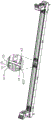
Fig. 1 is a perspective view of the card edge connector of the present invention.
Fig. 2 is an enlarged view of a circled portion of the card edge connector shown in fig. 1.
Fig. 3 is a perspective view of the card edge connector shown in fig. 1 from another perspective.
Fig. 4 is an enlarged view of a circled portion of the card edge connector shown in fig. 3.
Fig. 5 is a perspective view of the metal shell shown in fig. 3.
Fig. 6 is a perspective view of the card edge connector shown in fig. 3 from another perspective.
Fig. 7 is a perspective view of the card edge connector shown in fig. 6 from another perspective.
Fig. 8 is a sectional view of the card edge connector shown in fig. 1 along a-a direction.
[ detailed description ] embodiments
The following detailed description will further illustrate the invention in conjunction with the above-described figures.
Referring to fig. 1 to 4, the present invention discloses a card edge connector 100, which includes an elongated insulative housing 10, a plurality of conductive terminals 20 retained in the insulative housing 10, a latch 30 pivotally connected to the insulative housing 10, and a metal shell 40 covering the insulative housing 10. The insulating body 10 includes two longitudinal side walls, a card insertion slot is formed between the two side walls, and the plurality of conductive terminals 20 are arranged along the inner wall surfaces of the side walls. The insulating body 10 is provided with a main body 11 extending in a longitudinal direction and a tower 12 projecting upward from the main body 11. The metal housing 40 is engaged with the light guide plate for fixing the light guide plate between two adjacent card edge connectors 100.
Referring to fig. 5 to 8, the metal shell 40 includes two long walls 41 and 42 attached to the outer wall surface of the side wall. The long walls 41 and 42 are provided with positioning portions 412 and 422 protruding outward, and the positioning portions 412 and 422 are used for fixing the light guide plate disposed beside the card edge connector 100 in the longitudinal direction. The positioning portions 412 and 422 have a rectangular structure directly punched and formed by the long walls 41 and 42. The long walls 41, 42 are further provided with pressing portions 414, 416, 424, 426 extending outward and downward, and the pressing portions 414, 416, 424, 426 are used for pressing the upper edge of the light guide plate downward. The locating portions 412, 422 are located on the long walls 41, 42 adjacent their bottom edges. The press sections 414, 416, 424, 426 are located adjacent the top edges of the longwalls 41, 42. The long walls 41, 42 include first and second long walls 41, 42 disposed opposite to each other and first and second end walls 44, 45 connecting the first and second long walls 41, 42. The first long wall 41 is provided with four first positioning portions 412 arranged in the longitudinal direction. The second long wall 42 is provided with four second positioning portions 422 arranged in the longitudinal direction. The first long wall 41 includes a first body 411 and first and second protruding portions 413 and 415 extending upward from two ends of the first body 411. The first protruding portion 413 is provided with a first pressing portion 414. The second protruding portion 415 is provided with a second pressing portion 416. The second sidewall 42 includes a second main body 421, and third and fourth protrusions 423 and 425 extending upward from two ends of the second main body 421. The third extending portion 423 is provided with a third pressing portion 424. The fourth protruding part 425 is provided with a fourth pressing part 426. The third extension 423 is provided to correspond to the first extension 413. The fourth extension 425 is disposed corresponding to the second extension 415. The first pressing portion 414 and the third pressing portion 424 are disposed in a staggered manner along a transverse direction perpendicular to the longitudinal direction. The second pressing portion 416 and the fourth pressing portion 426 are also disposed in a staggered manner along the transverse direction. The first and second positioning portions 412 and 422 are engaged with the concave holes of the light guide plate, so as to fix the light guide plate between the metal shells 40 of two adjacent card edge connectors 100. The first, second, third and fourth pressing parts 414, 416, 424 and 426 press the upper edge of the light guide plate downward, thereby preventing the light guide plate from flying outward. The first end wall 44 includes a first portion 441 and a second portion 442, and the first portion 441 and the second portion 442 are in a dovetail-type snap-fit. The second end wall 45 includes a third portion 451 and a fourth portion 452, and the third portion 451 and the fourth portion 452 are also in a dovetail-type engagement. The dovetail groove type buckling structure prevents the end wall from tilting.
Referring to fig. 5, the top edges of the first long wall 41 and the second long wall 42 are respectively provided with a first folding part 417 and a second folding part 427 which are folded inwards. The first groove 13 and the second groove 14 extending along the longitudinal direction are respectively disposed on two lateral sides of the top surface of the insulating body 10. The first folding part 417 and the second folding part 427 are respectively clamped in the first groove 13 and the second groove 14. The first folded part 417 and the second folded part 427 are C-shaped. Referring to fig. 6, the bottom edges of the first long wall 41 and the second long wall 42 are respectively provided with a first hook 418 and a second hook 428 bent inward. The first hook 418 and the second hook 428 are respectively fixed to two sides of the bottom of the insulating body 10 by riveting. The metal shell 40 is fixed to the insulating body 10 through the first and second folded portions 417 and 427 and the first and second hooks 418 and 428. Referring to fig. 7, the metal shell 40 further includes a connecting portion 43 connecting the first and second long walls 41 and 42, a receiving slot 15 extending along the transverse direction is formed on the top surface of the insulating housing 10, and the connecting portion 43 is received in the receiving slot 15. The insulating body 10 is further provided with a protrusion 16 protruding into the receiving groove 15, and the protrusion 16 clamps the connecting portion 43, so as to prevent the metal shell 40 from shaking.
In summary, the above is only a preferred embodiment of the present invention, and should not be limited to the scope of the present invention, and all the simple equivalent changes and modifications made according to the claims and the content of the specification should be covered by the scope of the present invention.
Claims (8)
1. The utility model provides a card edge connector, its includes lengthwise insulator, fixes a plurality of conductive terminal in insulator and cladding in insulator's metal casing, insulator includes two lengthwise side walls, form the card slot of pegging graft between two side walls, a plurality of conductive terminal are followed the side wall internal face is arranged, metal casing is including pasting two longwalls that are in the side wall outer wall face, its characterized in that: the metal shell is provided with an outward protruding positioning part at the lower end of each long wall and an outward and downward extending pressing part at the upper end of each long wall, the positioning part is used for fixing a light guide plate arranged beside the card edge connector in the lengthwise direction, the pressing part is used for pressing the upper edge of the light guide plate downward, and the positioning part is of a rectangular structure formed by directly stamping the long walls.
2. The card edge connector according to claim 1, wherein: the positioning part is positioned at the position, adjacent to the bottom edge of the long wall, and the pressing part is positioned at the position, adjacent to the top edge of the long wall, of the long wall.
3. The card edge connector as claimed in claim 2, wherein: the insulating body comprises a main body part and tower-shaped parts arranged at two ends of the main body part, the long wall comprises a body part corresponding to the main body part and a protruding part corresponding to the tower-shaped parts, and the pressing part is arranged on the protruding part and extends downwards to be flush with the top surface of the body part.
4. The card edge connector according to claim 1, wherein: the pressing parts of the two long walls are arranged in a staggered mode in the transverse direction perpendicular to the longitudinal direction.
5. The card edge connector according to claim 1, wherein: the top edge of the long wall is provided with a turnover part which is turned inwards, and the turnover part is fixed in a groove arranged on the top surface of the insulating body.
6. The card edge connector according to claim 1, wherein: the two ends of the two long walls are respectively and vertically bent to form end walls which are mutually buckled, and the end walls are in dovetail groove type buckling.
7. The card edge connector according to claim 1, wherein: the bottom edge of the long wall is provided with a clamping hook which is bent inwards, and the clamping hook is clamped at the bottom of the insulating body.
8. The card edge connector according to claim 1, wherein: the long wall is provided with four positioning parts and two pressing parts.
Priority Applications (2)
| Application Number | Priority Date | Filing Date | Title |
|---|---|---|---|
| CN201710196913.9A CN106936007B (en) | 2017-03-29 | 2017-03-29 | Card edge connector |
| TW107109533A TWI791496B (en) | 2017-03-29 | 2018-03-21 | Card edge connector |
Applications Claiming Priority (1)
| Application Number | Priority Date | Filing Date | Title |
|---|---|---|---|
| CN201710196913.9A CN106936007B (en) | 2017-03-29 | 2017-03-29 | Card edge connector |
Publications (2)
| Publication Number | Publication Date |
|---|---|
| CN106936007A CN106936007A (en) | 2017-07-07 |
| CN106936007B true CN106936007B (en) | 2021-10-26 |
Family
ID=59425917
Family Applications (1)
| Application Number | Title | Priority Date | Filing Date |
|---|---|---|---|
| CN201710196913.9A Active CN106936007B (en) | 2017-03-29 | 2017-03-29 | Card edge connector |
Country Status (2)
| Country | Link |
|---|---|
| CN (1) | CN106936007B (en) |
| TW (1) | TWI791496B (en) |
Families Citing this family (1)
| Publication number | Priority date | Publication date | Assignee | Title |
|---|---|---|---|---|
| CN110829071A (en) * | 2018-08-07 | 2020-02-21 | 鸿富锦精密工业(武汉)有限公司 | Expansion card connecting device and circuit board |
Citations (7)
| Publication number | Priority date | Publication date | Assignee | Title |
|---|---|---|---|---|
| TWM253930U (en) * | 2003-11-27 | 2004-12-21 | Hon Hai Prec Ind Co Ltd | Electrical connector |
| CN2674697Y (en) * | 2003-10-31 | 2005-01-26 | 富士康(昆山)电脑接插件有限公司 | Electric connector |
| CN2884569Y (en) * | 2006-02-06 | 2007-03-28 | 番禺得意精密电子工业有限公司 | Card edge connector |
| CN201204309Y (en) * | 2008-03-25 | 2009-03-04 | 富士康(昆山)电脑接插件有限公司 | Electric connector |
| CN203288791U (en) * | 2013-04-16 | 2013-11-13 | 富士康(昆山)电脑接插件有限公司 | Card edge connector and combination thereof |
| CN204834944U (en) * | 2015-06-11 | 2015-12-02 | 富士康(昆山)电脑接插件有限公司 | Edge blocking type connector |
| CN107546508A (en) * | 2016-06-28 | 2018-01-05 | 富士康(昆山)电脑接插件有限公司 | Bayonet connector |
Family Cites Families (1)
| Publication number | Priority date | Publication date | Assignee | Title |
|---|---|---|---|---|
| TWM515720U (en) * | 2015-08-10 | 2016-01-11 | 鴻騰精密科技股份有限公司 | Electrical connector |
-
2017
- 2017-03-29 CN CN201710196913.9A patent/CN106936007B/en active Active
-
2018
- 2018-03-21 TW TW107109533A patent/TWI791496B/en active
Patent Citations (7)
| Publication number | Priority date | Publication date | Assignee | Title |
|---|---|---|---|---|
| CN2674697Y (en) * | 2003-10-31 | 2005-01-26 | 富士康(昆山)电脑接插件有限公司 | Electric connector |
| TWM253930U (en) * | 2003-11-27 | 2004-12-21 | Hon Hai Prec Ind Co Ltd | Electrical connector |
| CN2884569Y (en) * | 2006-02-06 | 2007-03-28 | 番禺得意精密电子工业有限公司 | Card edge connector |
| CN201204309Y (en) * | 2008-03-25 | 2009-03-04 | 富士康(昆山)电脑接插件有限公司 | Electric connector |
| CN203288791U (en) * | 2013-04-16 | 2013-11-13 | 富士康(昆山)电脑接插件有限公司 | Card edge connector and combination thereof |
| CN204834944U (en) * | 2015-06-11 | 2015-12-02 | 富士康(昆山)电脑接插件有限公司 | Edge blocking type connector |
| CN107546508A (en) * | 2016-06-28 | 2018-01-05 | 富士康(昆山)电脑接插件有限公司 | Bayonet connector |
Also Published As
| Publication number | Publication date |
|---|---|
| TWI791496B (en) | 2023-02-11 |
| TW201841430A (en) | 2018-11-16 |
| CN106936007A (en) | 2017-07-07 |
Similar Documents
| Publication | Publication Date | Title |
|---|---|---|
| EP3203583B1 (en) | Wire connection terminal structure | |
| CN107871941B (en) | Card edge connector | |
| CN106785543B (en) | Bayonet connector | |
| US20070238357A1 (en) | Electrical connector | |
| US20140011378A1 (en) | Universal serial bus connector perpendicularly mounted on a printed circuit board | |
| CN108418022A (en) | Plate is to template radio frequency socket | |
| US7717730B2 (en) | Camera module connector with disassembling structure | |
| CN101834362A (en) | Electrical connector system | |
| CN106936007B (en) | Card edge connector | |
| CN201018082Y (en) | Electronic card connector | |
| CN208401102U (en) | Plate is to template radio-frequency maser | |
| CN202034569U (en) | Electric connector assembly | |
| CN106997993B (en) | Card edge connector | |
| CN201038461Y (en) | Electric connector | |
| KR100517651B1 (en) | Contact Pin in SIM Slide Connector | |
| US8861223B2 (en) | Electronic device with connecting assemblies | |
| CN112382893A (en) | Board-to-board connector | |
| CN106711644B (en) | Double-contact connector suitable for mating and PCB connecting structure | |
| CN200987001Y (en) | Electrical connector | |
| JP3208852U (en) | Connection terminal and terminal assembly | |
| CN204834946U (en) | Edge blocking type connector | |
| CN217036089U (en) | Card edge connector | |
| CN210296676U (en) | Electrical connector | |
| CN211700800U (en) | Card edge connector | |
| CN217009636U (en) | Male and female plug terminal |
Legal Events
| Date | Code | Title | Description |
|---|---|---|---|
| PB01 | Publication | ||
| PB01 | Publication | ||
| SE01 | Entry into force of request for substantive examination | ||
| SE01 | Entry into force of request for substantive examination | ||
| GR01 | Patent grant | ||
| GR01 | Patent grant |