CN106894844B - Cooling circuit for multiwall vane - Google Patents
Cooling circuit for multiwall vane Download PDFInfo
- Publication number
- CN106894844B CN106894844B CN201611190537.4A CN201611190537A CN106894844B CN 106894844 B CN106894844 B CN 106894844B CN 201611190537 A CN201611190537 A CN 201611190537A CN 106894844 B CN106894844 B CN 106894844B
- Authority
- CN
- China
- Prior art keywords
- leg
- cooling
- blade
- cooling circuit
- serpentine
- Prior art date
- Legal status (The legal status is an assumption and is not a legal conclusion. Google has not performed a legal analysis and makes no representation as to the accuracy of the status listed.)
- Active
Links
- 238000001816 cooling Methods 0.000 title claims abstract description 254
- 230000008878 coupling Effects 0.000 claims abstract description 10
- 238000010168 coupling process Methods 0.000 claims abstract description 10
- 238000005859 coupling reaction Methods 0.000 claims abstract description 10
- 108091006146 Channels Proteins 0.000 description 46
- 239000007789 gas Substances 0.000 description 15
- 238000005266 casting Methods 0.000 description 7
- 108090000862 Ion Channels Proteins 0.000 description 5
- 102000004310 Ion Channels Human genes 0.000 description 5
- 238000000034 method Methods 0.000 description 5
- 239000000567 combustion gas Substances 0.000 description 4
- 238000005219 brazing Methods 0.000 description 3
- 239000012528 membrane Substances 0.000 description 3
- 229910000831 Steel Inorganic materials 0.000 description 2
- 239000000446 fuel Substances 0.000 description 2
- 229910052751 metal Inorganic materials 0.000 description 2
- 239000002184 metal Substances 0.000 description 2
- 238000005058 metal casting Methods 0.000 description 2
- 239000010959 steel Substances 0.000 description 2
- 238000003466 welding Methods 0.000 description 2
- 239000000956 alloy Substances 0.000 description 1
- 229910045601 alloy Inorganic materials 0.000 description 1
- 239000000919 ceramic Substances 0.000 description 1
- 239000000463 material Substances 0.000 description 1
- 230000007246 mechanism Effects 0.000 description 1
- 150000002739 metals Chemical class 0.000 description 1
- 239000000203 mixture Substances 0.000 description 1
- 238000010248 power generation Methods 0.000 description 1
- 230000001737 promoting effect Effects 0.000 description 1
Images


Classifications
-
- F—MECHANICAL ENGINEERING; LIGHTING; HEATING; WEAPONS; BLASTING
- F01—MACHINES OR ENGINES IN GENERAL; ENGINE PLANTS IN GENERAL; STEAM ENGINES
- F01D—NON-POSITIVE DISPLACEMENT MACHINES OR ENGINES, e.g. STEAM TURBINES
- F01D5/00—Blades; Blade-carrying members; Heating, heat-insulating, cooling or antivibration means on the blades or the members
- F01D5/12—Blades
- F01D5/14—Form or construction
- F01D5/18—Hollow blades, i.e. blades with cooling or heating channels or cavities; Heating, heat-insulating or cooling means on blades
- F01D5/187—Convection cooling
-
- F—MECHANICAL ENGINEERING; LIGHTING; HEATING; WEAPONS; BLASTING
- F01—MACHINES OR ENGINES IN GENERAL; ENGINE PLANTS IN GENERAL; STEAM ENGINES
- F01D—NON-POSITIVE DISPLACEMENT MACHINES OR ENGINES, e.g. STEAM TURBINES
- F01D5/00—Blades; Blade-carrying members; Heating, heat-insulating, cooling or antivibration means on the blades or the members
- F01D5/12—Blades
- F01D5/14—Form or construction
- F01D5/18—Hollow blades, i.e. blades with cooling or heating channels or cavities; Heating, heat-insulating or cooling means on blades
- F01D5/186—Film cooling
-
- F—MECHANICAL ENGINEERING; LIGHTING; HEATING; WEAPONS; BLASTING
- F02—COMBUSTION ENGINES; HOT-GAS OR COMBUSTION-PRODUCT ENGINE PLANTS
- F02C—GAS-TURBINE PLANTS; AIR INTAKES FOR JET-PROPULSION PLANTS; CONTROLLING FUEL SUPPLY IN AIR-BREATHING JET-PROPULSION PLANTS
- F02C3/00—Gas-turbine plants characterised by the use of combustion products as the working fluid
- F02C3/04—Gas-turbine plants characterised by the use of combustion products as the working fluid having a turbine driving a compressor
-
- F—MECHANICAL ENGINEERING; LIGHTING; HEATING; WEAPONS; BLASTING
- F05—INDEXING SCHEMES RELATING TO ENGINES OR PUMPS IN VARIOUS SUBCLASSES OF CLASSES F01-F04
- F05D—INDEXING SCHEME FOR ASPECTS RELATING TO NON-POSITIVE-DISPLACEMENT MACHINES OR ENGINES, GAS-TURBINES OR JET-PROPULSION PLANTS
- F05D2220/00—Application
- F05D2220/30—Application in turbines
- F05D2220/32—Application in turbines in gas turbines
-
- F—MECHANICAL ENGINEERING; LIGHTING; HEATING; WEAPONS; BLASTING
- F05—INDEXING SCHEMES RELATING TO ENGINES OR PUMPS IN VARIOUS SUBCLASSES OF CLASSES F01-F04
- F05D—INDEXING SCHEME FOR ASPECTS RELATING TO NON-POSITIVE-DISPLACEMENT MACHINES OR ENGINES, GAS-TURBINES OR JET-PROPULSION PLANTS
- F05D2240/00—Components
- F05D2240/20—Rotors
- F05D2240/30—Characteristics of rotor blades, i.e. of any element transforming dynamic fluid energy to or from rotational energy and being attached to a rotor
- F05D2240/305—Characteristics of rotor blades, i.e. of any element transforming dynamic fluid energy to or from rotational energy and being attached to a rotor related to the pressure side of a rotor blade
-
- F—MECHANICAL ENGINEERING; LIGHTING; HEATING; WEAPONS; BLASTING
- F05—INDEXING SCHEMES RELATING TO ENGINES OR PUMPS IN VARIOUS SUBCLASSES OF CLASSES F01-F04
- F05D—INDEXING SCHEME FOR ASPECTS RELATING TO NON-POSITIVE-DISPLACEMENT MACHINES OR ENGINES, GAS-TURBINES OR JET-PROPULSION PLANTS
- F05D2240/00—Components
- F05D2240/20—Rotors
- F05D2240/30—Characteristics of rotor blades, i.e. of any element transforming dynamic fluid energy to or from rotational energy and being attached to a rotor
- F05D2240/307—Characteristics of rotor blades, i.e. of any element transforming dynamic fluid energy to or from rotational energy and being attached to a rotor related to the tip of a rotor blade
-
- F—MECHANICAL ENGINEERING; LIGHTING; HEATING; WEAPONS; BLASTING
- F05—INDEXING SCHEMES RELATING TO ENGINES OR PUMPS IN VARIOUS SUBCLASSES OF CLASSES F01-F04
- F05D—INDEXING SCHEME FOR ASPECTS RELATING TO NON-POSITIVE-DISPLACEMENT MACHINES OR ENGINES, GAS-TURBINES OR JET-PROPULSION PLANTS
- F05D2250/00—Geometry
- F05D2250/10—Two-dimensional
- F05D2250/18—Two-dimensional patterned
- F05D2250/185—Two-dimensional patterned serpentine-like
-
- F—MECHANICAL ENGINEERING; LIGHTING; HEATING; WEAPONS; BLASTING
- F05—INDEXING SCHEMES RELATING TO ENGINES OR PUMPS IN VARIOUS SUBCLASSES OF CLASSES F01-F04
- F05D—INDEXING SCHEME FOR ASPECTS RELATING TO NON-POSITIVE-DISPLACEMENT MACHINES OR ENGINES, GAS-TURBINES OR JET-PROPULSION PLANTS
- F05D2260/00—Function
- F05D2260/20—Heat transfer, e.g. cooling
- F05D2260/205—Cooling fluid recirculation, i.e. after cooling one or more components is the cooling fluid recovered and used elsewhere for other purposes
Abstract
The invention relates to a cooling circuit for a multiwall vane. Specifically, a cooling system according to an embodiment includes: a serpentine cooling circuit comprising a first leg extending in a first direction, a second leg extending in a second direction, and a turn fluidly coupling the first leg and the second leg; and an air supply cavity for supplying cooling air to the serpentine cooling circuit; wherein a first leg of the serpentine cooling circuit extends radially outward from and at least partially covers at least one central plenum of the multi-walled blade, and wherein a second leg of the serpentine cooling circuit extends radially outward from and at least partially covers a first set of near-wall cooling channels of the multi-walled blade.
Description
Cross Reference to Related Applications
This application is related to co-pending U.S. applications having application numbers 14/977078, 14/977102, 14/977124, 14/977152, 14/977175, 14/977200, 14/977228, and 14/977270, having GE docket numbers 282168-1, 282169-1, 282171-1, 282174-1, 283464-1, 283467-1, 283463-1, and 284160-1, all filed on 21/12/2015.
Technical Field
The present disclosure relates generally to turbine systems, and more particularly to a cooling circuit for a tip region of a multiwall blade.
Background
Gas turbine systems are one example of turbomachines that are widely used in fields such as power generation. Conventional gas turbine systems include a compressor section, a combustor section, and a turbine section. During operation of the gas turbine system, various components in the system (such as turbine blades) are subjected to high temperature flows, which may cause component failure. Since higher temperature flows generally result in increased performance, efficiency, and power output of the gas turbine system, it is advantageous to cool components that are subjected to high temperature flows to allow the gas turbine system to operate at elevated temperatures.
Turbine blades often contain a complex labyrinth of internal cooling passages. Cooling air, such as that provided by a compressor of a gas turbine system, may pass through the internal cooling passages to cool the turbine blades.
The multi-walled turbine blade cooling system may include an internal near-wall cooling circuit. For example, such a near-wall cooling circuit may include near-wall cooling channels near the outer sidewall of a multi-walled blade. The near-wall cooling channels are typically smaller, requiring less cooling flow while still maintaining sufficient velocity for effective cooling to occur. Other, typically larger, less efficient cooling internal passages of the multi-walled blade may be used as a source of cooling air and may be used in one or more reuse circuits to collect and re-route the "used" cooling flow for redistribution to the lower heat load regions of the multi-walled blade. At the tip of the multiwall blade, the nearwall cooling channels and the low cooling efficiency internal channels are subjected to very high thermal loads.
Disclosure of Invention
A first aspect of the present disclosure provides a cooling system comprising: a serpentine cooling circuit (serpentine cooling circuit) including a first leg extending in a first direction, a second leg extending in a second direction, and a turn fluidly coupling the first leg and the second leg; and an air supply cavity for supplying cooling air to the serpentine cooling circuit; wherein a first leg of the serpentine cooling circuit extends radially outward from and at least partially covers at least one central plenum of the multi-walled blade, and wherein a second leg of the serpentine cooling circuit extends radially outward from and at least partially covers a first set of near-wall cooling channels of the multi-walled blade.
A second aspect of the present disclosure provides a multi-walled turbine blade comprising: a cooling system disposed within a multi-walled turbine blade, the cooling system comprising: a serpentine cooling circuit comprising a first leg extending in a first direction, a second leg extending in a second direction, and a turn fluidly coupling the first leg and the second leg; and an air supply cavity for supplying cooling air to the serpentine cooling circuit; wherein a first leg of the serpentine cooling circuit extends radially outward from and at least partially covers at least one central plenum of the multi-walled turbine blade, and wherein a second leg of the serpentine cooling circuit extends radially outward from and at least partially covers a first set of near-wall cooling channels of the multi-walled turbine blade.
A third aspect of the present disclosure provides a turbine comprising: a gas turbine system comprising a compressor component, a combustor component, and a turbine component, the turbine component comprising a plurality of turbine buckets, and wherein at least one of the turbine buckets comprises a multiwall blade; and a cooling system disposed within the multiwall blade, the cooling system comprising: a serpentine cooling circuit comprising a first leg extending in a first direction, a second leg extending in a second direction; and an air supply cavity for supplying cooling air to the serpentine cooling circuit; wherein a first leg of the serpentine cooling circuit extends radially outward from and at least partially covers at least one central plenum of the multi-walled blade, and wherein a second leg of the serpentine cooling circuit extends radially outward from and at least partially covers a first set of near-wall cooling channels of the multi-walled blade.
Technical solution 1. a cooling system includes:
a serpentine cooling circuit comprising a first leg extending in a first direction, a second leg extending in a second direction, and a turn fluidly coupling the first leg and the second leg; and
an air supply cavity for supplying cooling air to the serpentine cooling circuit;
wherein a first leg of the serpentine cooling circuit extends radially outward from and at least partially covers at least one central plenum of a multi-walled blade, and wherein a second leg of the serpentine cooling circuit extends radially outward from and at least partially covers a first set of near-wall cooling channels of the multi-walled blade.
Solution 3. the cooling system of solution 1, wherein a first leg of the serpentine cooling circuit extends from the air supply cavity toward a leading edge of the multi-walled blade, and wherein a second leg of the serpentine cooling circuit extends from the turn toward a trailing edge of the multi-walled blade.
Solution 5. the cooling system of solution 1, wherein the first leg of the serpentine cooling circuit extends across and at least partially covers the second set of near-wall cooling channels in the multi-walled blade.
The cooling system of claim 1, wherein at least one of the first or second legs of the serpentine cooling circuit comprises at least one tip film channel for directing the cooling air to the tip of the multi-wall blade to provide a tip film.
Solution 9. the cooling system of solution 1 wherein the cooling air is supplied to the air supply chamber from a central plenum or a near-wall cooling channel of the multiwall sheet.
a cooling system disposed within the multi-walled turbine blade, the cooling system comprising:
a serpentine cooling circuit comprising a first leg extending in a first direction, a second leg extending in a second direction, and a turn fluidly coupling the first leg and the second leg; and
an air supply cavity for supplying cooling air to the serpentine cooling circuit;
wherein a first leg of the serpentine cooling circuit extends radially outward from and at least partially covers at least one central plenum of the multi-walled turbine blade, and wherein a second leg of the serpentine cooling circuit extends radially outward from and at least partially covers a first set of near-wall cooling channels of the multi-walled turbine blade.
Solution 11. the multi-walled turbine blade of claim 10, wherein a first leg of the serpentine cooling circuit extends from the air supply cavity toward a trailing edge of the multi-walled blade, and wherein a second leg of the serpentine cooling circuit extends from the turn toward a leading edge of the multi-walled blade.
The multi-walled turbine blade of claim 10, wherein the first set of near-wall cooling channels are located near a pressure side of the multi-walled blade.
The multi-walled turbine blade of claim 14, wherein the second set of near-wall cooling channels are located near a suction side of the multi-walled blade.
The multi-walled turbine blade of claim 10, wherein at least one of the first or second legs of the serpentine cooling circuit includes at least one tip film channel for directing the cooling air to a tip of the multi-walled blade to provide a tip film.
The multi-walled turbine blade of claim 17, wherein the second leg of the serpentine cooling circuit comprises at least one pressure side membrane channel for directing the cooling air to the pressure side of the multi-walled blade to provide a pressure side membrane.
The multi-walled turbine blade of claim 18, wherein the cooling air is supplied to the air supply cavity from a central plenum or a near-wall cooling channel of the multi-walled blade.
Solution 19. the multi-walled turbine blade of solution 10, wherein the multi-walled turbine blade forms a portion of a turbine bucket, and wherein the turbine bucket includes a shank coupled to the multi-walled turbine blade.
The invention according to claim 20 provides a turbine comprising:
a gas turbine system comprising a compressor component, a combustor component, and a turbine component, the turbine component comprising a plurality of turbine buckets, and wherein at least one of the turbine buckets comprises a multi-walled blade; and
a cooling system disposed within the multi-walled blade, the cooling system comprising:
a serpentine cooling circuit comprising a first leg extending in a first direction, a second leg extending in a second direction, and a turn fluidly coupling the first leg and the second leg; and
an air supply cavity for supplying cooling air to the serpentine cooling circuit;
wherein a first leg of the serpentine cooling circuit extends radially outward from and at least partially covers at least one central plenum of the multi-wall blade, and wherein a second leg of the serpentine cooling circuit extends radially outward from and at least partially covers a first set of near-wall cooling channels of the multi-wall blade.
Illustrative aspects of the present disclosure address the issues described herein and/or other issues not discussed.
Drawings
These and other features of the present disclosure will be more readily understood from the following detailed description of the various aspects of the present disclosure taken in conjunction with the accompanying drawings that depict various embodiments of the disclosure.
FIG. 1 illustrates a perspective view of a turbine bucket including a multi-wall blade, according to an embodiment.
Figure 2 is a cross-sectional view of the multi-wall blade of figure 1 taken along line a-a in figure 1, in accordance with various embodiments.
Figure 3 is a cross-sectional view of a tip region of the multi-wall blade of figure 1 taken along line B-B in figure 1, in accordance with various embodiments.
Figure 4 is a cross-sectional view of a tip region of the multi-wall blade of figure 1 taken along line B-B in figure 1, in accordance with various embodiments.
Figure 5 is a cross-sectional view of a tip region of the multi-wall blade of figure 1 taken along line B-B in figure 1, in accordance with various embodiments.
Fig. 6-8 depict illustrative methods for forming a portion of a two-pass (two-pass) serpentine cooling circuit, in accordance with various embodiments.
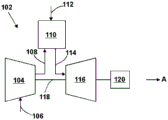
FIG. 9 is a schematic illustration of a gas turbine system, according to various embodiments.
It is noted that the drawings of the present disclosure are not necessarily to scale. The drawings are intended to depict only typical aspects of the disclosure, and therefore should not be considered as limiting the scope of the disclosure. In the drawings, like numbering represents like elements between the drawings.
Parts list
2 turbine bucket
4 handle part
6 multiwall leaf
8 pressure side
10 suction side
12 distal region
14 leading edge
16 trailing edge
18 near-wall cooling channel
20 center air chamber
22 tip
24 tip membrane
30 cooling channel
40 two-way serpentine cooling circuit
42 first leg
44 front air supply chamber
45 turning part
46 second leg
48 tip membrane channel
50 pressure side membrane channel
52 film
54 distal membrane channel
60 parts of a two-way cooling circuit
62 core
64 grooved core section
66 tip core segment
68 body core region
70 support rod
80 metal casting
82 opening
84 bolt
86 cavity rib
88 bottom
90 groove cavity
92 opening
102 gas turbine
104 compressor
106 air
108 compressed air
110 burner
112 fuel
114 combustion gas
116 turbine
118 shaft
120 load
140 two-way serpentine cooling circuit
142 first leg
144 air supply chamber
145 turning point
146 second leg
240 two-way serpentine cooling circuit
242 first leg portion
244 air supply chamber
245 at the turning point
246 second leg.
Detailed Description
In the drawings, for example in fig. 9, the "a" axis represents the axial orientation. As used herein, the terms "axial" and/or "axially" refer to the relative position/direction of an object along an axis a that is substantially parallel to the axis of rotation of the turbine (particularly the rotor section). Also as used herein, the terms "radial" and/or "radially" refer to the relative position/direction of an object along axis (r) that is substantially perpendicular to axis a and intersects axis a at only one location. Additionally, the terms "circumferential" and/or "circumferentially" refer to the relative position/direction of an object along a circumference (c) that surrounds, but does not intersect, axis a at any location.
As indicated above, the present disclosure relates generally to turbine systems, and more particularly to cooling circuits for cooling the tip region of multi-walled blades.
According to an embodiment, the cooling circuit is configured to cool a tip region of a multiwall blade of a gas turbine engine while providing protection for internal passages of low cooling efficiency and providing a cooling film. Protection may also be provided for near wall cooling channels of high cooling efficiency. The cooling circuit may include a two-pass serpentine cooling circuit that may be supplied with cooling air from the less efficient cooling internal passage or the near wall cooling passage. Air passing through the cooling circuit provides conventional cooling and is discharged as a cooling film to cool the tip region of the multi-walled blade.
Turning to FIG. 1, a perspective view of a turbine bucket 2 is shown. The turbine bucket 2 includes a shank 4 and a multiwall blade 6 coupled to the shank 4 and extending radially outward from the shank 4. The multiwall blade 6 includes a pressure side 8, an opposite suction side 10, and a tip region 12. The multiwall blade 16 also includes a leading edge 14 between the pressure side 8 and the suction side 10, and a trailing edge 16 between the pressure side 8 and the suction side 10 on a side opposite the leading edge 14.
The handle 4 and the multiwall blade 6 can each be formed from one or more metals (e.g., steel, alloys of steel, etc.) and can be formed according to conventional routes (e.g., cast, forged, or otherwise processed). The handle 4 and multiwall blade 6 can be integrally formed (e.g., cast, forged, three-dimensionally printed, etc.) or can be formed as separate components that are subsequently joined (e.g., via welding, brazing, bonding, or other coupling mechanisms).
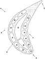
Figure 2 is a cross-sectional view of the multiwall blade 6 taken along line a-a of figure 1. As shown, the multiwall blade 6 can include an arrangement 30 of, for example, cooling channels, including a plurality of high efficiency, nearwall cooling channels 18 and one or more low cooling efficiency, internal channels 20 (hereinafter "central plenums"). Various cooling circuits may be provided using different combinations of the near-wall cooling channels 18 and the central plenum 20.
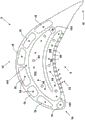
An embodiment comprising a two-way serpentine cooling circuit 40 is depicted in FIG. 3, which is a cross-sectional view of a multi-walled blade 6 taken along line B-B of FIG. 1. The two-way serpentine cooling circuit 40 is positioned radially outward (e.g., proximate the tip region 12 of the multi-walled blade 6) along the multi-walled blade 6 relative to the configuration of cooling channels 30 shown in FIG. 2. In this regard, in comparison to fig. 2 and 3, the two-pass serpentine cooling circuit 40 effectively "shields" the central plenum 20 and at least some of the nearwall cooling channels 18 from very high thermal loads that typically occur at the tip region 12 of the multiwall blade 6 during rotation of the multiwall blade 6 (e.g., in a gas turbine).
The two-pass serpentine cooling circuit 40 includes a first leg 42 that extends across and at least partially covers the central plenum 20. The first leg 42 extends rearwardly from the front air supply chamber 44 towards the trailing edge 16 of the multiwall blade 6. Although shown in FIG. 3 as extending across all of the central plenums 20, the first leg 42 of the two-pass serpentine cooling circuit 40 may extend substantially across one or more of the central plenums 20.
The two-pass serpentine cooling circuit 40 also includes a second leg 46 that extends across and at least partially covers a set (e.g., one or more) of the nearwall cooling channels 18 disposed near the pressure side 8 of the multiwall blade 6. A turn 45 disposed near the trailing edge 16 of the multiwall blade 6 fluidly couples the first leg 42 and the second leg 46 of the two-pass serpentine cooling circuit 40. The second leg 46 extends from the turn 45 towards the leading edge 14 of the multiwall blade 6. Comparing fig. 2 and 3, it can be seen that in this embodiment, the second leg 46 extends across all of the nearwall cooling channels 18 disposed near the pressure side 8 of the multiwall blade 6. In general, however, the second leg 46 of the two-pass serpentine cooling circuit 40 may extend across one or more near-wall cooling channels 18 disposed near the pressure side 8 of the multiwall vane 6.
Cooling air is supplied to the first leg 42 of the two-pass serpentine cooling circuit 40 via an air supply cavity 44. The air supply cavity 44 may be fluidly coupled to at least one of the central plenums 20 and receive cooling air therefrom. In other embodiments, the air supply cavity 44 may be fluidly coupled to and receive cooling air from at least one of the nearwall cooling channels 18. In either case, in this embodiment, the air supply chamber 44 is disposed near the leading edge 14 of the multiwall blade 6.
In fig. 3, and as seen in connection with fig. 1 and 2, cooling air flows from an air supply chamber 44 (e.g., out of the page in fig. 3) into the first leg 42, through a turn 45, and into the second leg 46. In the first and second legs 42, 46 and the turn 45 of the two-pass serpentine cooling circuit 40, the cooling air absorbs heat (e.g., via convention) from the adjacent portions of the tip region 12 of the multi-walled blade 6, shielding the underlying near-wall cooling channel 18 and the central plenum 20 from excessive heat. The cooling air flows out of the first and second legs 42, 46 (e.g., out of the page in fig. 3) via at least one tip film passage 48. The cooling air is directed by the tip film passage 48 to the tip 22 of the multi-walled blade 6. Cooling air is discharged from the tip 22 of the multi-walled blade 6 to the tip film 24 to provide tip film cooling. In addition, cooling air is discharged from second leg 46 to pressure side 8 of multi-walled blade 6 through at least one pressure side film passage 50 to provide film 52 for pressure side film cooling.
Cooling air may also be discharged from at least one of the near-wall cooling channels 18 to the tip 22 to provide tip film cooling. For example, as shown in FIG. 3, at least one of the nearwall cooling channels 18 near the suction side 10 of the multiwall blade 6 may be fluidly coupled to the tip 22 of the multiwall blade 6 by at least one tip film channel 54. The cooling air is discharged from the tip film passage 54 (out of the page in FIG. 3) to provide the tip film 24 for tip film cooling.
In another embodiment, an aft air supply cavity 144 disposed near the trailing edge 16 of the multiwall blade 6 can be used to supply cooling air to the two-pass serpentine cooling circuit 140. This configuration is depicted in fig. 4, seen in conjunction with fig. 1 and 2.
The two-pass serpentine cooling circuit 140 shown in fig. 4 includes a first leg 142 that extends across and at least partially covers at least the central plenum 20. The first leg 142 extends forward from the rear air supply chamber 144 toward the leading edge 14 of the multiwall blade 6. The second leg 146 of the two-pass serpentine cooling circuit 140 extends across and at least partially covers a set (e.g., one or more) of the nearwall cooling channels 18 disposed near the pressure side 8 of the multiwall vane 6. A turn 45 disposed near the leading edge 14 of the multiwall blade 6 fluidly couples the first leg 142 and the second leg 146 of the two-pass serpentine cooling circuit 140. The second leg 146 extends from the turn 145 towards the trailing edge 16 of the multiwall blade 6.
The air supply cavity 144 may be fluidly coupled to and receive cooling air from at least one of the center plenums 20 or at least one of the near-wall cooling channels 18. As with the embodiment shown in FIG. 3, the two-pass serpentine cooling circuit 140 depicted in FIG. 4 is configured to shield the central plenum 20 and at least some of the pressure side nearwall cooling channels 18 from the very high thermal loads that typically occur at the tip region 12 of the multiwall blade 6. Further, the two-pass serpentine cooling circuit 140 depicted in FIG. 4 is configured to provide the tip film 24 and the pressure side film 52 for tip film cooling and pressure side film cooling, respectively.
In yet another embodiment, as depicted in FIG. 5, as seen in conjunction with FIGS. 1 and 2, the first leg 242 of the two-pass serpentine cooling circuit 240 may expand to extend beyond the central plenum 20 and cover not only the central plenum 20 (e.g., as in FIG. 3) but also a set (e.g., one or more) of the nearwall cooling channels 18 disposed near the suction side 10 of the multi-walled blade 6. The first leg 242 extends from the air supply chamber 244 towards the trailing edge 16 of the multiwall blade 6. As in the embodiment depicted in FIG. 3, the second leg 246 of the two-pass serpentine cooling circuit 240 extends across and at least partially covers a set (e.g., one or more) of the nearwall cooling channels 18 disposed near the pressure side 8 of the multiwall blade 6. A turn 245 disposed near the trailing edge 16 of the multiwall blade 6 fluidly couples the first leg 242 and the second leg 246 of the two-pass serpentine cooling circuit 240. The second leg 246 extends from the turn 245 towards the leading edge 14 of the multiwall blade 6.
The air supply cavity 244 may be fluidly coupled to and receive cooling air from at least one of the near-wall cooling channels 18 or at least one of the central plenums 20. The two-pass serpentine cooling circuit 240 depicted in FIG. 5 is configured to shield the central plenum 20, at least some of the suction side nearwall cooling channels 18, and at least some of the pressure side nearwall cooling channels 18 from the very high thermal loads that typically occur at the tip region 12 of the multi-wall blade 6. Further, similar to the embodiment shown in FIG. 3, the two-pass serpentine cooling circuit 240 depicted in FIG. 5 is configured to provide the tip film 24 and the pressure side film 52 for tip film cooling and pressure side film cooling, respectively.
In fig. 5, the air supply cavity 244 is arranged near the leading edge 14 of the multiwall blade 6, with the first leg 242 of the two-pass serpentine cooling circuit 240 extending towards the trailing edge 16 of the multiwall blade 6. However, similar to the embodiment shown in FIG. 4, the air supply cavity 244 may be arranged near the trailing edge 16 of the multi-walled blade 6, with the first leg 242 of the two-way serpentine cooling circuit 240 extending towards the trailing edge 16 of the multi-walled blade 6.
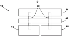
Fig. 6-8 depict an illustrative method for forming a portion 60 of a two-pass serpentine cooling circuit 40, according to an embodiment. A cross-sectional view of a core 62 (e.g., a ceramic core) for use in casting the portion 60 of the two-pass serpentine cooling circuit 40 is shown in fig. 6.
The core 62 includes a groove core section 64, a tip core section 66, and at least one body core section 68. Support posts 70 secure and separate the individual core sections 64, 66, 68. The fluted core section 64, after casting, will form a cavity at the tip 22 of the multiwall blade 6, which is open radially outward. The tip core section 66 will form one of the legs 42, 46 of the two-pass serpentine cooling circuit 40 after casting. The body core segment 68 will form at least one of the near-wall cooling channel 18 or the central plenum 20 after casting.
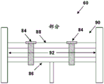
An example of a metal casting 80 produced using the core 62 (e.g., using known casting techniques) is depicted in fig. 7. The casting 80 includes a plurality of openings 82 corresponding to the location of the support rods 70 in the core 62. According to an embodiment, as shown in fig. 8, each opening 82 may be sealed using a metal (e.g., brazing material) plug 84. For example, the plug 84 may be inserted into the opening 82, press fit or otherwise inserted into the cavity rib 86 of the casting 80, and secured (e.g., via brazing) to the bottom 88 of the groove cavity 90 and the cavity rib 86. In this regard, the plug pin 84 extends completely through the opening 92 between the inner cavity rib 86 and the bottom 88 of the groove cavity 90, preventing cooling air from leaking out of the opening 92 through the opening 82.
The opening 92 between the inner cavity rib 86 and the bottom 88 of the groove cavity 90 may be used, for example, to provide one of the legs 42, 46 of the two-pass serpentine cooling circuit 40 with the plug 84 oriented substantially perpendicular to the flow of cooling air through the opening 92 (e.g., into or out of the page in fig. 8). In this position, the plug 84 not only seals the opening 82 on the opposite side of the opening 92, but also acts as a cooling pin, increasing the cooling efficiency of the two-pass serpentine cooling circuit 40 by promoting convective heat flow and turbulent air flow. A possible location of the latch 84 in the first and second legs 42, 46 of the two-way serpentine cooling circuit 40 is shown in fig. 3-5. The depicted position of the latch 84 in fig. 3-5 is for illustration only and not intended to be limiting.
FIG. 9 shows a schematic view of a gas turbine 102 as may be used herein. The gas turbine 102 may include a compressor 104. The compressor 104 compresses a flow of incoming air 106. The compressor 104 delivers a flow of compressed air 108 to a combustor 110. The combustor 110 mixes the flow of compressed air 108 with a flow of pressurized fuel 112 and ignites the mixture to create a flow of combustion gases 114. Although only a single combustor 110 is shown, the gas turbine 102 may include any number of combustors 110. The flow of combustion gases 114 is, in turn, delivered to a turbine 116, which generally includes a plurality of turbine buckets 2 (FIG. 1). The flow of combustion gases 114 drives a turbine 116 to produce mechanical work. The mechanical work produced in the turbine 116 drives the compressor 104 via a shaft 118, and may be used to drive an external load 120 (such as an electrical generator and/or the like).
In various embodiments, components described as "coupled" to each other may be joined along one or more interfaces. In some embodiments, these interfaces may include connections between different components, and in other cases, these interfaces may include firmly and/or integrally formed interconnections. That is, in some cases, components that are "coupled" to each other may be formed simultaneously to define a single continuous component. However, in other embodiments, these coupled components may be formed as separate parts and subsequently joined by known processes (e.g., fastening, ultrasonic welding, bonding).
When an element or layer is referred to as being "on," "engaged to," "connected to" or "coupled to" another element, it can be directly on, engaged, connected or coupled to the other element or intervening elements may be present. In contrast, when an element is referred to as being "directly on," "directly engaged to," "directly connected to" or "directly coupled to" another element, there may be no intervening elements or layers present. Other words used to describe the relationship between elements should be interpreted in a similar manner (e.g., "between" versus "directly between," "adjacent" versus "directly adjacent," etc.). As used herein, the term "and/or" includes any and all combinations of one or more of the associated listed items.
The terminology used herein is for the purpose of describing particular embodiments only and is not intended to be limiting of the disclosure. As used herein, the singular forms "a", "an" and "the" are intended to include the plural forms as well, unless the context clearly indicates otherwise. It will be further understood that the terms "comprises" and/or "comprising," when used in this specification, specify the presence of stated features, integers, steps, operations, elements, and/or components, but do not preclude the presence or addition of one or more other features, integers, steps, operations, elements, components, and/or groups thereof.
This written description uses examples to disclose the invention, including the best mode, and also to enable any person skilled in the art to practice the invention, including making and using any devices or systems and performing any incorporated methods. The patentable scope of the invention is defined by the claims, and may include other examples that occur to those skilled in the art. Such other examples are intended to be within the scope of the claims if they have structural elements that do not differ from the literal language of the claims, or if they include equivalent structural elements with insubstantial differences from the literal languages of the claims.
Claims (10)
1. A cooling system, comprising:
a serpentine cooling circuit (40,140,240) including a first leg (42,142,242) extending in a first direction, a second leg (46,146,246) extending in a second direction, and a knuckle (45,145,245) fluidly coupling the first leg (42,142,242) and the second leg (46,146,246); and
an air supply cavity (44,144,244) for supplying cooling air to the serpentine cooling circuit (40,140, 240);
wherein a first leg (42,142,242) of the serpentine cooling circuit (40,140,240) extends radially outward from and at least partially covers at least one central plenum (20) of a multi-walled blade (6), and wherein a second leg (46,146,246) of the serpentine cooling circuit (40,140,240) extends radially outward from and at least partially covers a first set of near-wall cooling channels (18) of the multi-walled blade.
2. The cooling system of claim 1, wherein a first leg (42,242) of the serpentine cooling circuit (40,240) extends from the air supply cavity (44,244) toward a trailing edge (16) of the multi-walled blade, and wherein a second leg (46,246) of the serpentine cooling circuit (40,240) extends from the turn (45,245) toward a leading edge (14) of the multi-walled blade.
3. The cooling system of claim 1, wherein a first leg (142) of the serpentine cooling circuit (140) extends from the air supply cavity (144) toward a leading edge (14) of the multi-walled blade, and wherein a second leg (146) of the serpentine cooling circuit (140) extends from the turn (145) toward a trailing edge (16) of the multi-walled blade.
4. The cooling system according to claim 1, wherein the first set of nearwall cooling channels (18) is located near a pressure side (8) of the multiwall vane.
5. The cooling system of claim 1, wherein a first leg (42,142,242) of the serpentine cooling circuit (40,140,240) extends over and at least partially covers a second set of near-wall cooling channels (18) in the multi-wall blade, wherein the second set of near-wall cooling channels (18) is located near a suction side (10) of the multi-wall blade.
6. The cooling system of claim 1, wherein at least one of a first leg (42,142,242) or a second leg (46,146,246) of the serpentine cooling circuit (40,140,240) includes at least one tip film channel (48) for directing the cooling air to a tip (22) of the multiwall blade to provide a tip film (24).
7. The cooling system of claim 1, wherein a second leg (46,146,246) of the serpentine cooling circuit (40,140,240) comprises at least one pressure side film channel (50) for directing the cooling air to a pressure side (8) of the multiwall sheet to provide a pressure side film (52).
8. The cooling system of claim 1, wherein the cooling air is supplied to the air supply cavity (44,144,244) from a central plenum (20) or a near-wall cooling channel (18) of the multiwall blade.
9. A multi-walled turbine blade (6) comprising a cooling system arranged within the multi-walled turbine blade, characterized in that the cooling system comprises:
a serpentine cooling circuit (40,140,240) including a first leg (42,142,242) extending in a first direction, a second leg (46,146,246) extending in a second direction, and a knuckle (45,145,245) fluidly coupling the first leg (42,142,242) and the second leg (46,146,246); and
an air supply cavity (44,144,244) for supplying cooling air to the serpentine cooling circuit (40,140, 240);
wherein a first leg (42,142,242) of the serpentine cooling circuit (40,140,240) extends radially outward from and at least partially covers at least one central plenum (20) of the multi-wall turbine blade, and wherein a second leg (46,146,246) of the serpentine cooling circuit (40,140,240) extends radially outward from and at least partially covers a first set of near-wall cooling channels (18) of the multi-wall turbine blade.
10. A turbomachine (102), comprising:
a gas turbine system (102) comprising a compressor component (104), a combustor component (110), and a turbine component (116), the turbine component (116) comprising a plurality of turbine buckets (2), and wherein at least one of the turbine buckets comprises a multi-walled blade (6); and
a cooling system disposed within the multi-walled blade,
characterized in that the cooling system comprises:
a serpentine cooling circuit (40,140,240), the serpentine cooling circuit (40,140,240) including a first leg (42,142,242) extending in a first direction, a second leg (46,146,246) extending in a second direction, and a turn (45,145,245) fluidly coupling the first leg (42,142,242) and the second leg (46,146,246); and
an air supply cavity (44,144,244) for supplying cooling air to the serpentine cooling circuit (40,140, 240);
wherein a first leg (42,142,242) of the serpentine cooling circuit (40,140,240) extends radially outward from and at least partially covers at least one central plenum (20) of the multi-wall blade, and wherein a second leg (46,146,246) of the serpentine cooling circuit (40,140,240) extends radially outward from and at least partially covers a first set of near-wall cooling channels (18) of the multi-wall blade.
Applications Claiming Priority (2)
| Application Number | Priority Date | Filing Date | Title |
|---|---|---|---|
| US14/977247 | 2015-12-21 | ||
| US14/977,247 US9926788B2 (en) | 2015-12-21 | 2015-12-21 | Cooling circuit for a multi-wall blade |
Publications (2)
| Publication Number | Publication Date |
|---|---|
| CN106894844A CN106894844A (en) | 2017-06-27 |
| CN106894844B true CN106894844B (en) | 2021-01-15 |
Family
ID=58994105
Family Applications (1)
| Application Number | Title | Priority Date | Filing Date |
|---|---|---|---|
| CN201611190537.4A Active CN106894844B (en) | 2015-12-21 | 2016-12-21 | Cooling circuit for multiwall vane |
Country Status (5)
| Country | Link |
|---|---|
| US (1) | US9926788B2 (en) |
| JP (1) | JP7073039B2 (en) |
| CN (1) | CN106894844B (en) |
| CH (1) | CH711981A2 (en) |
| DE (1) | DE102016124019A1 (en) |
Families Citing this family (15)
| Publication number | Priority date | Publication date | Assignee | Title |
|---|---|---|---|---|
| US10060269B2 (en) | 2015-12-21 | 2018-08-28 | General Electric Company | Cooling circuits for a multi-wall blade |
| US9976425B2 (en) | 2015-12-21 | 2018-05-22 | General Electric Company | Cooling circuit for a multi-wall blade |
| US10119405B2 (en) | 2015-12-21 | 2018-11-06 | General Electric Company | Cooling circuit for a multi-wall blade |
| US9932838B2 (en) | 2015-12-21 | 2018-04-03 | General Electric Company | Cooling circuit for a multi-wall blade |
| US10053989B2 (en) | 2015-12-21 | 2018-08-21 | General Electric Company | Cooling circuit for a multi-wall blade |
| US10221696B2 (en) | 2016-08-18 | 2019-03-05 | General Electric Company | Cooling circuit for a multi-wall blade |
| US10227877B2 (en) | 2016-08-18 | 2019-03-12 | General Electric Company | Cooling circuit for a multi-wall blade |
| US10267162B2 (en) * | 2016-08-18 | 2019-04-23 | General Electric Company | Platform core feed for a multi-wall blade |
| US10208607B2 (en) | 2016-08-18 | 2019-02-19 | General Electric Company | Cooling circuit for a multi-wall blade |
| US10208608B2 (en) | 2016-08-18 | 2019-02-19 | General Electric Company | Cooling circuit for a multi-wall blade |
| EP3421724A1 (en) * | 2017-06-26 | 2019-01-02 | Siemens Aktiengesellschaft | Compressor aerofoil |
| US10570750B2 (en) | 2017-12-06 | 2020-02-25 | General Electric Company | Turbine component with tip rail cooling passage |
| US10408065B2 (en) | 2017-12-06 | 2019-09-10 | General Electric Company | Turbine component with rail coolant directing chamber |
| JP7234006B2 (en) | 2019-03-29 | 2023-03-07 | 三菱重工業株式会社 | High temperature parts and method for manufacturing high temperature parts |
| CN109882247B (en) * | 2019-04-26 | 2021-08-20 | 哈尔滨工程大学 | Multi-channel internal cooling gas turbine blade with air vent inner wall |
Citations (5)
| Publication number | Priority date | Publication date | Assignee | Title |
|---|---|---|---|---|
| US4753575A (en) * | 1987-08-06 | 1988-06-28 | United Technologies Corporation | Airfoil with nested cooling channels |
| US5403159A (en) * | 1992-11-30 | 1995-04-04 | United Technoligies Corporation | Coolable airfoil structure |
| US6220817B1 (en) * | 1997-11-17 | 2001-04-24 | General Electric Company | AFT flowing multi-tier airfoil cooling circuit |
| US6491496B2 (en) * | 2001-02-23 | 2002-12-10 | General Electric Company | Turbine airfoil with metering plates for refresher holes |
| US7780415B2 (en) * | 2007-02-15 | 2010-08-24 | Siemens Energy, Inc. | Turbine blade having a convergent cavity cooling system for a trailing edge |
Family Cites Families (57)
| Publication number | Priority date | Publication date | Assignee | Title |
|---|---|---|---|---|
| DE2121711A1 (en) | 1970-07-31 | 1972-02-03 | Thaelmann Schwermaschbau Veb | Wire press automatic cut out |
| JPS5114519A (en) * | 1974-07-25 | 1976-02-05 | Mitsui Shipbuilding Eng | REIKYAKUTAABINDOYOKU |
| DE2821691A1 (en) | 1977-05-23 | 1978-12-21 | Pavel Dipl Ing Chem Buncak | Lock indicator for steered wheels - has electronic or mechanical sensor on steering column and indicator on dashboard |
| US4147513A (en) | 1977-09-26 | 1979-04-03 | Bendix Autolite Corporation | Method and apparatus for measuring the O2 content of a gas |
| DE2821681A1 (en) | 1978-05-18 | 1979-11-22 | Moto Meter Ag | Light barrier system for electrically operated car windows - with each light barrier operating at its own frequency which is different from others |
| DE2834631A1 (en) | 1978-08-08 | 1980-02-28 | Donald R Dotson | SKATEBOARD SKI |
| DE2834641A1 (en) | 1978-08-08 | 1980-02-28 | Bosch Gmbh Robert | MULTI-STAGE TRANSISTOR AMPLIFIER |
| SE438907B (en) | 1978-09-22 | 1985-05-13 | Kawaguchiya Firearms | LOCK ARRANGEMENT FOR PATTERN AND PATTERN DRIVER IN AUTOMATIC WEAPON |
| US4474532A (en) | 1981-12-28 | 1984-10-02 | United Technologies Corporation | Coolable airfoil for a rotary machine |
| GB2121483B (en) | 1982-06-08 | 1985-02-13 | Rolls Royce | Cooled turbine blade for a gas turbine engine |
| JPH06102963B2 (en) * | 1983-12-22 | 1994-12-14 | 株式会社東芝 | Gas turbine air cooling blade |
| JPS61279702A (en) * | 1985-06-06 | 1986-12-10 | Toshiba Corp | Air cooled guide vane for gas turbine |
| US5813835A (en) | 1991-08-19 | 1998-09-29 | The United States Of America As Represented By The Secretary Of The Air Force | Air-cooled turbine blade |
| US5296308A (en) | 1992-08-10 | 1994-03-22 | Howmet Corporation | Investment casting using core with integral wall thickness control means |
| US5853044A (en) | 1996-04-24 | 1998-12-29 | Pcc Airfoils, Inc. | Method of casting an article |
| GB9901218D0 (en) | 1999-01-21 | 1999-03-10 | Rolls Royce Plc | Cooled aerofoil for a gas turbine engine |
| US6196792B1 (en) | 1999-01-29 | 2001-03-06 | General Electric Company | Preferentially cooled turbine shroud |
| US6416284B1 (en) | 2000-11-03 | 2002-07-09 | General Electric Company | Turbine blade for gas turbine engine and method of cooling same |
| US6478535B1 (en) | 2001-05-04 | 2002-11-12 | Honeywell International, Inc. | Thin wall cooling system |
| FR2829175B1 (en) | 2001-08-28 | 2003-11-07 | Snecma Moteurs | COOLING CIRCUITS FOR GAS TURBINE BLADES |
| FR2829174B1 (en) | 2001-08-28 | 2006-01-20 | Snecma Moteurs | IMPROVEMENTS IN COOLING CIRCUITS FOR GAS TURBINE BLADE |
| US6974308B2 (en) | 2001-11-14 | 2005-12-13 | Honeywell International, Inc. | High effectiveness cooled turbine vane or blade |
| US7217097B2 (en) | 2005-01-07 | 2007-05-15 | Siemens Power Generation, Inc. | Cooling system with internal flow guide within a turbine blade of a turbine engine |
| US7303376B2 (en) | 2005-12-02 | 2007-12-04 | Siemens Power Generation, Inc. | Turbine airfoil with outer wall cooling system and inner mid-chord hot gas receiving cavity |
| US7686581B2 (en) | 2006-06-07 | 2010-03-30 | General Electric Company | Serpentine cooling circuit and method for cooling tip shroud |
| US7780413B2 (en) | 2006-08-01 | 2010-08-24 | Siemens Energy, Inc. | Turbine airfoil with near wall inflow chambers |
| US7527475B1 (en) | 2006-08-11 | 2009-05-05 | Florida Turbine Technologies, Inc. | Turbine blade with a near-wall cooling circuit |
| US7625178B2 (en) | 2006-08-30 | 2009-12-01 | Honeywell International Inc. | High effectiveness cooled turbine blade |
| US7722324B2 (en) | 2006-09-05 | 2010-05-25 | United Technologies Corporation | Multi-peripheral serpentine microcircuits for high aspect ratio blades |
| US7607891B2 (en) | 2006-10-23 | 2009-10-27 | United Technologies Corporation | Turbine component with tip flagged pedestal cooling |
| US8591189B2 (en) | 2006-11-20 | 2013-11-26 | General Electric Company | Bifeed serpentine cooled blade |
| US8047790B1 (en) | 2007-01-17 | 2011-11-01 | Florida Turbine Technologies, Inc. | Near wall compartment cooled turbine blade |
| US7819629B2 (en) | 2007-02-15 | 2010-10-26 | Siemens Energy, Inc. | Blade for a gas turbine |
| US7862299B1 (en) | 2007-03-21 | 2011-01-04 | Florida Turbine Technologies, Inc. | Two piece hollow turbine blade with serpentine cooling circuits |
| US7785072B1 (en) | 2007-09-07 | 2010-08-31 | Florida Turbine Technologies, Inc. | Large chord turbine vane with serpentine flow cooling circuit |
| US8087891B1 (en) | 2008-01-23 | 2012-01-03 | Florida Turbine Technologies, Inc. | Turbine blade with tip region cooling |
| CN101586477B (en) * | 2008-05-23 | 2011-04-13 | 中国科学院工程热物理研究所 | Turbulent baffle heat transfer enhancing device with jet impact function |
| US8192146B2 (en) | 2009-03-04 | 2012-06-05 | Siemens Energy, Inc. | Turbine blade dual channel cooling system |
| US8157505B2 (en) | 2009-05-12 | 2012-04-17 | Siemens Energy, Inc. | Turbine blade with single tip rail with a mid-positioned deflector portion |
| US8292582B1 (en) | 2009-07-09 | 2012-10-23 | Florida Turbine Technologies, Inc. | Turbine blade with serpentine flow cooling |
| US8616845B1 (en) | 2010-06-23 | 2013-12-31 | Florida Turbine Technologies, Inc. | Turbine blade with tip cooling circuit |
| US8794921B2 (en) | 2010-09-30 | 2014-08-05 | General Electric Company | Apparatus and methods for cooling platform regions of turbine rotor blades |
| CN102182518B (en) | 2011-06-08 | 2013-09-04 | 河南科技大学 | Turbine cooling blade |
| US8734108B1 (en) | 2011-11-22 | 2014-05-27 | Florida Turbine Technologies, Inc. | Turbine blade with impingement cooling cavities and platform cooling channels connected in series |
| US9109454B2 (en) * | 2012-03-01 | 2015-08-18 | General Electric Company | Turbine bucket with pressure side cooling |
| US8678766B1 (en) | 2012-07-02 | 2014-03-25 | Florida Turbine Technologies, Inc. | Turbine blade with near wall cooling channels |
| US20140096538A1 (en) | 2012-10-05 | 2014-04-10 | General Electric Company | Platform cooling of a turbine blade assembly |
| US8920123B2 (en) * | 2012-12-14 | 2014-12-30 | Siemens Aktiengesellschaft | Turbine blade with integrated serpentine and axial tip cooling circuits |
| CN104420887B (en) * | 2013-08-30 | 2016-06-15 | 哈尔滨汽轮机厂有限责任公司 | A kind of turbine of gas turbine |
| US9366194B2 (en) | 2013-09-05 | 2016-06-14 | General Electric Company | Method and system for controlling gas turbine performance with a variable backflow margin |
| US20150152738A1 (en) * | 2013-12-02 | 2015-06-04 | George Liang | Turbine airfoil cooling passage with diamond turbulator |
| US9879547B2 (en) | 2013-12-30 | 2018-01-30 | General Electric Company | Interior cooling circuits in turbine blades |
| US20150184538A1 (en) * | 2013-12-30 | 2015-07-02 | General Electric Company | Interior cooling circuits in turbine blades |
| US9995149B2 (en) | 2013-12-30 | 2018-06-12 | General Electric Company | Structural configurations and cooling circuits in turbine blades |
| US10294799B2 (en) * | 2014-11-12 | 2019-05-21 | United Technologies Corporation | Partial tip flag |
| US9845694B2 (en) | 2015-04-22 | 2017-12-19 | United Technologies Corporation | Flow directing cover for engine component |
| US9863538B2 (en) | 2015-04-27 | 2018-01-09 | United Technologies Corporation | Gas turbine engine brush seal with supported tip |
-
2015
- 2015-12-21 US US14/977,247 patent/US9926788B2/en active Active
-
2016
- 2016-12-12 DE DE102016124019.2A patent/DE102016124019A1/en active Pending
- 2016-12-15 CH CH01657/16A patent/CH711981A2/en not_active Application Discontinuation
- 2016-12-15 JP JP2016242825A patent/JP7073039B2/en active Active
- 2016-12-21 CN CN201611190537.4A patent/CN106894844B/en active Active
Patent Citations (5)
| Publication number | Priority date | Publication date | Assignee | Title |
|---|---|---|---|---|
| US4753575A (en) * | 1987-08-06 | 1988-06-28 | United Technologies Corporation | Airfoil with nested cooling channels |
| US5403159A (en) * | 1992-11-30 | 1995-04-04 | United Technoligies Corporation | Coolable airfoil structure |
| US6220817B1 (en) * | 1997-11-17 | 2001-04-24 | General Electric Company | AFT flowing multi-tier airfoil cooling circuit |
| US6491496B2 (en) * | 2001-02-23 | 2002-12-10 | General Electric Company | Turbine airfoil with metering plates for refresher holes |
| US7780415B2 (en) * | 2007-02-15 | 2010-08-24 | Siemens Energy, Inc. | Turbine blade having a convergent cavity cooling system for a trailing edge |
Also Published As
| Publication number | Publication date |
|---|---|
| JP2017122445A (en) | 2017-07-13 |
| DE102016124019A1 (en) | 2017-06-22 |
| JP7073039B2 (en) | 2022-05-23 |
| CN106894844A (en) | 2017-06-27 |
| CH711981A2 (en) | 2017-06-30 |
| US20170175547A1 (en) | 2017-06-22 |
| US9926788B2 (en) | 2018-03-27 |
Similar Documents
| Publication | Publication Date | Title |
|---|---|---|
| CN106894844B (en) | Cooling circuit for multiwall vane | |
| CN106894845B (en) | Cooling circuit for multiwall vane | |
| CN106894846B (en) | Cooling circuit for multiwall vane | |
| CN107035417B (en) | Cooling circuit for multiwall vane | |
| US10781698B2 (en) | Cooling circuits for a multi-wall blade | |
| CN107989657B (en) | Turbine blade with trailing edge cooling circuit | |
| JP2017122445A5 (en) | ||
| US20170175544A1 (en) | Cooling circuits for a multi-wall blade | |
| EP3336310B1 (en) | Partially wrapped trailing edge cooling circuit with pressure side serpentine cavities | |
| EP3284908B1 (en) | Multi-wall blade with cooling circuit | |
| JP6924021B2 (en) | Platform core supply for multi-wall blades | |
| CN107989655B (en) | Cooling circuit for multiwall vane |
Legal Events
| Date | Code | Title | Description |
|---|---|---|---|
| PB01 | Publication | ||
| PB01 | Publication | ||
| SE01 | Entry into force of request for substantive examination | ||
| SE01 | Entry into force of request for substantive examination | ||
| GR01 | Patent grant | ||
| GR01 | Patent grant | ||
| TR01 | Transfer of patent right |
Effective date of registration: 20240103 Address after: Swiss Baden Patentee after: GENERAL ELECTRIC CO. LTD. Address before: New York State, USA Patentee before: General Electric Co. |
|
| TR01 | Transfer of patent right |