CN106888043B - Self-adaptive parameter adjustment method of hybrid pre-coding millimeter wave transmission system - Google Patents

Self-adaptive parameter adjustment method of hybrid pre-coding millimeter wave transmission system Download PDF

Info

Publication number
CN106888043B
CN106888043B CN201611269597.5A CN201611269597A CN106888043B CN 106888043 B CN106888043 B CN 106888043B CN 201611269597 A CN201611269597 A CN 201611269597A CN 106888043 B CN106888043 B CN 106888043B
Authority
CN
China
Prior art keywords
radio frequency
frequency links
links
received signal
power consumption
Prior art date
Legal status (The legal status is an assumption and is not a legal conclusion. Google has not performed a legal analysis and makes no representation as to the accuracy of the status listed.)
Active
Application number
CN201611269597.5A
Other languages
Chinese (zh)
Other versions
CN106888043A (en
Inventor
杨秀梅
张武雄
张梦莹
杨旸
王海峰
Current Assignee (The listed assignees may be inaccurate. Google has not performed a legal analysis and makes no representation or warranty as to the accuracy of the list.)
Hunan Huazigan Iot Technology Co ltd
Shanghai Micro Nano Electronics R&d Center
Original Assignee
Shanghai Research Center for Wireless Communications
Priority date (The priority date is an assumption and is not a legal conclusion. Google has not performed a legal analysis and makes no representation as to the accuracy of the date listed.)
Filing date
Publication date
Application filed by Shanghai Research Center for Wireless Communications filed Critical Shanghai Research Center for Wireless Communications
Priority to CN201611269597.5A priority Critical patent/CN106888043B/en
Publication of CN106888043A publication Critical patent/CN106888043A/en
Priority to EP17185161.1A priority patent/EP3343795B1/en
Priority to US15/671,985 priority patent/US10333748B2/en
Application granted granted Critical
Publication of CN106888043B publication Critical patent/CN106888043B/en
Active legal-status Critical Current
Anticipated expiration legal-status Critical

Links

Images

Classifications

    • HELECTRICITY
    • H04ELECTRIC COMMUNICATION TECHNIQUE
    • H04LTRANSMISSION OF DIGITAL INFORMATION, e.g. TELEGRAPHIC COMMUNICATION
    • H04L25/00Baseband systems
    • H04L25/02Details ; arrangements for supplying electrical power along data transmission lines
    • H04L25/03Shaping networks in transmitter or receiver, e.g. adaptive shaping networks
    • H04L25/03891Spatial equalizers
    • H04L25/03961Spatial equalizers design criteria
    • HELECTRICITY
    • H04ELECTRIC COMMUNICATION TECHNIQUE
    • H04BTRANSMISSION
    • H04B7/00Radio transmission systems, i.e. using radiation field
    • H04B7/02Diversity systems; Multi-antenna system, i.e. transmission or reception using multiple antennas
    • H04B7/04Diversity systems; Multi-antenna system, i.e. transmission or reception using multiple antennas using two or more spaced independent antennas
    • H04B7/0413MIMO systems
    • H04B7/0456Selection of precoding matrices or codebooks, e.g. using matrices antenna weighting
    • HELECTRICITY
    • H04ELECTRIC COMMUNICATION TECHNIQUE
    • H04BTRANSMISSION
    • H04B17/00Monitoring; Testing
    • H04B17/30Monitoring; Testing of propagation channels
    • H04B17/309Measuring or estimating channel quality parameters
    • HELECTRICITY
    • H04ELECTRIC COMMUNICATION TECHNIQUE
    • H04BTRANSMISSION
    • H04B7/00Radio transmission systems, i.e. using radiation field
    • H04B7/02Diversity systems; Multi-antenna system, i.e. transmission or reception using multiple antennas
    • H04B7/04Diversity systems; Multi-antenna system, i.e. transmission or reception using multiple antennas using two or more spaced independent antennas
    • H04B7/06Diversity systems; Multi-antenna system, i.e. transmission or reception using multiple antennas using two or more spaced independent antennas at the transmitting station
    • H04B7/0686Hybrid systems, i.e. switching and simultaneous transmission
    • H04B7/0691Hybrid systems, i.e. switching and simultaneous transmission using subgroups of transmit antennas
    • H04B7/0693Hybrid systems, i.e. switching and simultaneous transmission using subgroups of transmit antennas switching off a diversity branch, e.g. to save power
    • HELECTRICITY
    • H04ELECTRIC COMMUNICATION TECHNIQUE
    • H04BTRANSMISSION
    • H04B7/00Radio transmission systems, i.e. using radiation field
    • H04B7/02Diversity systems; Multi-antenna system, i.e. transmission or reception using multiple antennas
    • H04B7/04Diversity systems; Multi-antenna system, i.e. transmission or reception using multiple antennas using two or more spaced independent antennas
    • H04B7/08Diversity systems; Multi-antenna system, i.e. transmission or reception using multiple antennas using two or more spaced independent antennas at the receiving station
    • H04B7/0868Hybrid systems, i.e. switching and combining
    • H04B7/0874Hybrid systems, i.e. switching and combining using subgroups of receive antennas
    • H04B7/0877Hybrid systems, i.e. switching and combining using subgroups of receive antennas switching off a diversity branch, e.g. to save power
    • HELECTRICITY
    • H04ELECTRIC COMMUNICATION TECHNIQUE
    • H04WWIRELESS COMMUNICATION NETWORKS
    • H04W52/00Power management, e.g. TPC [Transmission Power Control], power saving or power classes
    • H04W52/02Power saving arrangements
    • H04W52/0209Power saving arrangements in terminal devices
    • H04W52/0225Power saving arrangements in terminal devices using monitoring of external events, e.g. the presence of a signal
    • H04W52/0229Power saving arrangements in terminal devices using monitoring of external events, e.g. the presence of a signal where the received signal is a wanted signal
    • HELECTRICITY
    • H04ELECTRIC COMMUNICATION TECHNIQUE
    • H04WWIRELESS COMMUNICATION NETWORKS
    • H04W52/00Power management, e.g. TPC [Transmission Power Control], power saving or power classes
    • H04W52/02Power saving arrangements
    • H04W52/0209Power saving arrangements in terminal devices
    • H04W52/0225Power saving arrangements in terminal devices using monitoring of external events, e.g. the presence of a signal
    • H04W52/0245Power saving arrangements in terminal devices using monitoring of external events, e.g. the presence of a signal according to signal strength
    • HELECTRICITY
    • H04ELECTRIC COMMUNICATION TECHNIQUE
    • H04WWIRELESS COMMUNICATION NETWORKS
    • H04W52/00Power management, e.g. TPC [Transmission Power Control], power saving or power classes
    • H04W52/02Power saving arrangements
    • H04W52/0209Power saving arrangements in terminal devices
    • H04W52/0261Power saving arrangements in terminal devices managing power supply demand, e.g. depending on battery level
    • H04W52/0274Power saving arrangements in terminal devices managing power supply demand, e.g. depending on battery level by switching on or off the equipment or parts thereof
    • H04W52/028Power saving arrangements in terminal devices managing power supply demand, e.g. depending on battery level by switching on or off the equipment or parts thereof switching on or off only a part of the equipment circuit blocks
    • HELECTRICITY
    • H04ELECTRIC COMMUNICATION TECHNIQUE
    • H04BTRANSMISSION
    • H04B7/00Radio transmission systems, i.e. using radiation field
    • H04B7/02Diversity systems; Multi-antenna system, i.e. transmission or reception using multiple antennas
    • H04B7/04Diversity systems; Multi-antenna system, i.e. transmission or reception using multiple antennas using two or more spaced independent antennas
    • H04B7/06Diversity systems; Multi-antenna system, i.e. transmission or reception using multiple antennas using two or more spaced independent antennas at the transmitting station
    • H04B7/0613Diversity systems; Multi-antenna system, i.e. transmission or reception using multiple antennas using two or more spaced independent antennas at the transmitting station using simultaneous transmission
    • H04B7/0615Diversity systems; Multi-antenna system, i.e. transmission or reception using multiple antennas using two or more spaced independent antennas at the transmitting station using simultaneous transmission of weighted versions of same signal
    • H04B7/0617Diversity systems; Multi-antenna system, i.e. transmission or reception using multiple antennas using two or more spaced independent antennas at the transmitting station using simultaneous transmission of weighted versions of same signal for beam forming
    • HELECTRICITY
    • H04ELECTRIC COMMUNICATION TECHNIQUE
    • H04BTRANSMISSION
    • H04B7/00Radio transmission systems, i.e. using radiation field
    • H04B7/02Diversity systems; Multi-antenna system, i.e. transmission or reception using multiple antennas
    • H04B7/04Diversity systems; Multi-antenna system, i.e. transmission or reception using multiple antennas using two or more spaced independent antennas
    • H04B7/06Diversity systems; Multi-antenna system, i.e. transmission or reception using multiple antennas using two or more spaced independent antennas at the transmitting station
    • H04B7/0613Diversity systems; Multi-antenna system, i.e. transmission or reception using multiple antennas using two or more spaced independent antennas at the transmitting station using simultaneous transmission
    • H04B7/0615Diversity systems; Multi-antenna system, i.e. transmission or reception using multiple antennas using two or more spaced independent antennas at the transmitting station using simultaneous transmission of weighted versions of same signal
    • H04B7/0619Diversity systems; Multi-antenna system, i.e. transmission or reception using multiple antennas using two or more spaced independent antennas at the transmitting station using simultaneous transmission of weighted versions of same signal using feedback from receiving side
    • H04B7/0621Feedback content
    • H04B7/0623Auxiliary parameters, e.g. power control [PCB] or not acknowledged commands [NACK], used as feedback information
    • HELECTRICITY
    • H04ELECTRIC COMMUNICATION TECHNIQUE
    • H04BTRANSMISSION
    • H04B7/00Radio transmission systems, i.e. using radiation field
    • H04B7/02Diversity systems; Multi-antenna system, i.e. transmission or reception using multiple antennas
    • H04B7/04Diversity systems; Multi-antenna system, i.e. transmission or reception using multiple antennas using two or more spaced independent antennas
    • H04B7/08Diversity systems; Multi-antenna system, i.e. transmission or reception using multiple antennas using two or more spaced independent antennas at the receiving station
    • H04B7/0837Diversity systems; Multi-antenna system, i.e. transmission or reception using multiple antennas using two or more spaced independent antennas at the receiving station using pre-detection combining
    • H04B7/0842Weighted combining
    • H04B7/0848Joint weighting
    • HELECTRICITY
    • H04ELECTRIC COMMUNICATION TECHNIQUE
    • H04WWIRELESS COMMUNICATION NETWORKS
    • H04W52/00Power management, e.g. TPC [Transmission Power Control], power saving or power classes
    • H04W52/02Power saving arrangements
    • H04W52/0209Power saving arrangements in terminal devices
    • H04W52/0261Power saving arrangements in terminal devices managing power supply demand, e.g. depending on battery level
    • H04W52/0274Power saving arrangements in terminal devices managing power supply demand, e.g. depending on battery level by switching on or off the equipment or parts thereof
    • H04W52/028Power saving arrangements in terminal devices managing power supply demand, e.g. depending on battery level by switching on or off the equipment or parts thereof switching on or off only a part of the equipment circuit blocks
    • H04W52/0283Power saving arrangements in terminal devices managing power supply demand, e.g. depending on battery level by switching on or off the equipment or parts thereof switching on or off only a part of the equipment circuit blocks with sequential power up or power down of successive circuit blocks, e.g. switching on the local oscillator before RF or mixer stages
    • YGENERAL TAGGING OF NEW TECHNOLOGICAL DEVELOPMENTS; GENERAL TAGGING OF CROSS-SECTIONAL TECHNOLOGIES SPANNING OVER SEVERAL SECTIONS OF THE IPC; TECHNICAL SUBJECTS COVERED BY FORMER USPC CROSS-REFERENCE ART COLLECTIONS [XRACs] AND DIGESTS
    • Y02TECHNOLOGIES OR APPLICATIONS FOR MITIGATION OR ADAPTATION AGAINST CLIMATE CHANGE
    • Y02DCLIMATE CHANGE MITIGATION TECHNOLOGIES IN INFORMATION AND COMMUNICATION TECHNOLOGIES [ICT], I.E. INFORMATION AND COMMUNICATION TECHNOLOGIES AIMING AT THE REDUCTION OF THEIR OWN ENERGY USE
    • Y02D30/00Reducing energy consumption in communication networks
    • Y02D30/70Reducing energy consumption in communication networks in wireless communication networks

Landscapes

  • Engineering & Computer Science (AREA)
  • Computer Networks & Wireless Communication (AREA)
  • Signal Processing (AREA)
  • Power Engineering (AREA)
  • Quality & Reliability (AREA)
  • Physics & Mathematics (AREA)
  • Electromagnetism (AREA)
  • Radio Transmission System (AREA)
  • Mobile Radio Communication Systems (AREA)
  • Transmitters (AREA)

Abstract

The invention discloses a self-adaptive parameter adjusting method of a hybrid precoding millimeter wave transmission system. The method comprises the following steps: and interacting the number of the radio frequency links to be opened between the sending end and the receiving end. And the receiving end calculates the number of the radio frequency links to be started according to the received signal power when the radio frequency links with different numbers are started and the total power consumption when the radio frequency links with different numbers are started. The invention adaptively selects the number of the radio frequency links to be opened under the condition of balancing the power consumption and the speed, thereby achieving the optimization of the power consumption and the speed.

Description

Self-adaptive parameter adjustment method of hybrid pre-coding millimeter wave transmission system
Technical Field
The invention relates to a self-adaptive parameter adjustment method of a hybrid pre-coding millimeter wave transmission system, belonging to the technical field of wireless communication.
Background
As is known, the millimeter wave band provides a wider wireless spectrum, and can greatly increase the network capacity, and is one of the key technologies of the fifth generation mobile communication (5G). Because the power consumption of the millimeter wave radio frequency link is large, two performance indexes of speed and power consumption need to be considered simultaneously when evaluating the millimeter wave transmission performance. Millimeter wave systems are generally configured with a limited number of radio frequency links, and how to select an appropriate number of radio frequency links according to channel propagation characteristics is an important issue for millimeter wave system transmission.
Due to radio frequency power consumption, a plurality of antennas in a millimeter wave system generally share one radio frequency link, and the number of configured radio frequency links is smaller than that of antennas. Therefore, hybrid precoding combining analog precoding and digital precoding becomes an important preprocessing mode for millimeter wave wireless transmission. In an analog domain, a transmitting or receiving antenna array controls the beam direction by adjusting the phase shift of the antenna array, and in a digital domain, signals of a plurality of radio frequency links are combined through matrix operation. Increasing the number of rf links can effectively increase the signal reception strength and increase the transmission rate, but also increases the power consumption overhead. How to reasonably select the number of the opened radio frequency links is a key problem to be solved in practical application.
However, at present, research in hybrid precoding mainly focuses on the problems of designing a hybrid precoding codebook and fast beam search for a fixed number of radio frequency links. No study has shown how a suitable number of radio frequency links should be adaptively selected to open according to the channel propagation environment in which the user is located.
Disclosure of Invention
The invention aims to provide a self-adaptive parameter adjusting method of a hybrid precoding millimeter wave transmission system.
Another technical problem to be solved by the present invention is to provide a receiving end for millimeter wave transmission using hybrid precoding.
In order to achieve the purpose, the invention adopts the following technical scheme:
a self-adaptive parameter adjustment method of a hybrid precoding millimeter wave transmission system comprises the following steps:
and interacting the number of the radio frequency links to be opened between the sending end and the receiving end.
Preferably, the receiving end calculates the number of the radio frequency links to be opened according to the received signal power when the radio frequency links with different numbers are opened and the total power consumption when the radio frequency links with different numbers are opened, and sends the number of the radio frequency links to the sending end in an interactive mode.
Preferably, the total power consumption when the radio frequency links with different numbers are started at least comprises the total power consumption of the radio frequency links.
Preferably, the number of radio frequency links to be opened is determined by a selection metric value,
the selection metric value is a function of the received signal rate at which a particular number of radio frequency links are turned on and the total power consumption at which the particular number of radio frequency links are turned on.
Preferably, the method comprises the following steps:
the received signal power of the activated radio frequency link is calculated,
the total power consumption at startup of the radio frequency link is calculated,
a selection metric value is calculated for the activated radio frequency link,
the change in the value of the selection metric is compared,
and selecting the number of the radio frequency links to be opened for the interaction according to the change of the selection metric value.
A receiving end for millimeter wave transmission adopting hybrid pre-coding comprises a parameter estimation module,
and the number of radio frequency links to be opened is calculated by the parameter estimation and is used for interacting to the sending end.
Preferably, the receiving end calculates the number of the radio frequency links to be opened according to the received signal power when the radio frequency links of different numbers are opened and the total power consumption when the radio frequency links of different numbers are opened.
The invention adaptively selects the number of the radio frequency links to be opened under the condition of balancing the power consumption and the speed, thereby achieving the optimization of the power consumption and the speed.
Drawings
Fig. 1 is a schematic diagram of a hybrid precoded millimeter wave transmission system.
Detailed Description
The technical contents of the invention are described in detail below with reference to the accompanying drawings and specific embodiments.
The parameters in the figure are explained as follows. The sending end is configured: number of transmitting antennas NtNumber of radio frequency links
Figure BDA0001201228490000031
Number of independent data streams NsSimulating a precoding matrix FRFDigital precoding matrix FBB. And (3) receiving end configuration: number of receiving antennas NrNumber of radio frequency links
Figure BDA0001201228490000032
Analog domain merging matrix WRFMerging matrix of digital domainWBB. Different from the prior art, in addition to the above parameters, the proposed scheme adds a new parameter NfIs used to indicate the number of RF links that are turned on during actual transmission, wherein
Figure BDA0001201228490000033
Take single-user single-stream transmission as an example (N)s1), the dimensions of the matrixes are respectively as follows: fRF:Nt×Nf;FBB:Nf×1;WRF:Nr×Nf;WBB:NfX 1. The transmission process of the technical scheme of the invention is shown in figure 1.
The millimeter wave transmission method adopting hybrid precoding mainly comprises the following steps: the receiving end obtains the number N of the radio frequency links which need to be opened by the sending end and the receiving end through the calculation of the parameter estimation modulefWherein 1 is not more than NfK is less than or equal to K; parameter N is transmitted via a feedback linkfSending to the sending end, the sending end starts NfThe radio frequency link is used for signal transmission; receiving end opening NfThe radio frequency link receives signals.
< example one >
As shown in fig. 1, the millimeter wave transmission system of the present invention is composed of a transmitting end and a receiving end. The sending end and the receiving end both adopt mixed precoding and comprise a digital domain precoding module and an analog domain precoding module. The receiving end also comprises a parameter estimation module which is respectively connected with the digital domain pre-coding module and the analog domain pre-coding module of the receiving end.
In this embodiment, it is assumed that single-user single-stream millimeter wave transmission is adopted, and a large-scale antenna array is applied. The parameters take the following values: n is a radical oft=100,Nr=100,
Figure BDA0001201228490000034
Ns1. The antenna array adopts uniform linear arrays, the space between the antennas is half wavelength, and the number of the sending end analog domain codebooks is N1Wherein the first codebook flComprises the following steps:
Figure BDA0001201228490000035
Figure BDA0001201228490000036
N1=2Ntwhere phi is the starting angle, lambda is the wavelength, d is the antenna spacing, superscript (·)TRepresenting a transpose; the number of the receiving end analog domain codebooks is N2Wherein the ith codebook wlComprises the following steps:
Figure BDA0001201228490000041
N2=2Nrwherein
Figure BDA0001201228490000042
Is the angle of arrival. Both the sending end and the receiving end adopt Discrete Fourier Transform (DFT) codebooks in the digital domain. The channel model adopts an extended Saleh-Vallenzuela (SV) model, the model is a millimeter wave common channel model, and a channel matrix H is represented as:
Figure BDA0001201228490000043
wherein L is the number of spatially distributed diameters, alphalFor the complex gain of each path, the gain is,
Figure BDA0001201228490000044
in order to receive the antenna array response,
Figure BDA0001201228490000045
is the angle of arrival of the first path,
Figure BDA0001201228490000046
in order to transmit the antenna array response,
Figure BDA0001201228490000047
the starting angle of the first diameter is marked with (·)HRepresenting a conjugate transpose.
In this embodiment, let L be 10, αlSubject to the rayleigh distribution,
Figure BDA0001201228490000048
and
Figure BDA0001201228490000049
obeying the Laplace distribution, assuming that each radio frequency link consumes p048 mW. The noise power is denoted as σ2
For the one-time channel realization H, the receiving end firstly carries out beam search according to the prior art (such as ergodic search, multi-stage search and the like) and records the beam pair with the strongest energy in the received signal. In the present embodiment to
Figure BDA00012012284900000410
For the purpose of illustration, assume that the 4 strongest beam pairs are: { f1,w1},{f2,w2},{f3,w3},{f4,w4}; that is, the analog domain of the transmitting end adopts the beam codebook f1The receiving end adopts a wave beam codebook w in an analog domain1When the power of the received signal is strongest, the analog domain of the transmitting end adopts a wave beam codebook f2The receiving end adopts a wave beam codebook w in an analog domain2The received signal power is the next time, and so on.
Assuming that when 1, 2, 3, 4 rf links are respectively opened, that is, when the rf links with specific numbers of 1, 2, 3, 4 are opened, the digital domain pre-codes preset at the transmitting end and the receiving end are a respectively(1)=1,a(2),a(3),a(4);b(1)=1,b(2),b(3),b(4)(ii) a Wherein, the upper label (·)(1),(·)(2),(·)(3),(·)(4)Respectively representing vectors when the number of corresponding radio frequency links is 1, 2, 3 and 4. The vectors are taken from the columns of the corresponding DFT matrix, respectively. The corresponding received symbol is denoted by y1,y2,y3,y4And is also the diagonal element of matrix Y, and the off-diagonal element is zero.
As one of the preferred options, the feedback parameter may adopt binary bit quantization and then feedback the quantization bit.
The receiving end parameter estimation module (N) is described belowf) Calculate the answerMethod of starting the number of radio frequency links.
Arranging the received intensities of the signals in different angle directions from big to small, taking K received signals with the strongest energy for storage, and recording { w1,w2,…,wKIs the corresponding K receiving end analog beams, { f }1,f2,…,fKIs the corresponding K sending end analog beams, { y }1,y2,…,yKIs the corresponding received signal. Will { y1,y2,…,yKThe diagonal form is denoted Y, i.e. Y ═ diag (Y)1,y2,…,yK) Y is a K x K diagonal matrix with diagonal elements of { Y1,y2,…,yKAnd the off-diagonal elements are zero. Since the training beam transmitted during the beam training process is known, after the effect of the training sequence is removed,
Figure BDA0001201228490000051
wherein H is Nr×NtChannel matrix of (2), superscript (·)HRepresenting a conjugate transpose.
When i radio frequency links are supposed to be started, the transmitting end digital domain precoding vector and the receiving end digital domain combining vector are respectively expressed as:
Figure BDA0001201228490000052
i=1,2,…,K;
step 1: calculating the total power of the received signals for starting the i radio frequency links:
Figure BDA0001201228490000053
i=1,2, …, K. That is, the received signal powers when different radio frequency links are started are calculated respectively: q. q.s(1)=(b(1))HYa(1),q(2)=(b(2))HYa(2),q(3)=(b(3))HYa(3),q(4)=(b(4))HYa(4)
Step 2: calculating the total power consumption p when starting the i radio frequency links(i). AsIllustratively, the invention only considers the power consumption of the radio frequency links, and assumes that each radio frequency link has approximately the same power consumption, i.e., p(i)≈2i×p0Wherein p is0For each radio frequency link. Therefore, in this embodiment, when a certain number of radio links are turned on, the total radio frequency power consumption is as follows: p is a radical of(1)≈2p0,p(2)≈4p0,p(3)≈6p0,p(4)≈8p0. In particular implementations, the total power consumption may also include the power consumption of the baseband portion, e.g., p(i)≈2i×p0+tiWherein t isiThe power consumption of the base band when the i radio frequency links are started is disclosed.
And step 3: calculating the selection metric value when starting the i radio frequency links:
Figure BDA0001201228490000061
wherein i is 1,2,…,K,σ2For the total noise power, the expression represents the ratio of the rate and the power consumption. When the specific number is 1, 2, 3, 4, the selection metric values when the specific number of radio frequency links is turned on are:
Figure BDA0001201228490000062
as the number of open rf links increases, the selection metric changes accordingly. In this embodiment, every time a specific number of values is increased by 1, that is, every time a radio frequency link is opened, a selection metric value after the specific number of values is increased and a selection metric value before the specific number of values is increased are calculated, and the difference between the specific number of values and the selection metric value before the specific number of values is increased is subtracted, and an absolute value is taken as an incremental change of the selection metric value.
And 4, step 4: changes in the selection metric values are compared.
The change of the selected metric value in this embodiment is the incremental difference of the selected metric value, i.e., beta(2)(1)|,|β(3)(2)|,…,|β(K)(K-1)And if the increment is smaller than a preset threshold value epsilon, stopping comparison and determining the number of the radio frequency links needing to be opened. Wherein, the doorThe limit value is defined according to the user requirement, if the set threshold value is larger, the system emphasizes the power consumption requirement, if the set threshold value is smaller, the system emphasizes the rate requirement, and the threshold value is positive and real.
It will be appreciated that the choice of metric values may be made in other ways, for example,
Figure BDA0001201228490000063
that is, the numerator and denominator are multiplied by a weighting value of a positive real number, and different values of the weighting value indicate different requirements on rate and power consumption, where m is an examplet=mp1 in a special case. The variation of the measure can also be varied in other ways, e.g. in the form of a ratio, e.g.
Figure BDA0001201228490000064
And the like.
And 5: the number of radio frequency links to be opened is selected.
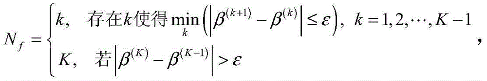
In the invention, the number of the radio frequency links to be opened is determined; a ratio of a received signal rate when a specific number of radio frequency links are turned on to a total radio frequency power consumption when the specific number of radio frequency links are turned on. This ratio may be the rate divided by the power consumption or the power consumption divided by the rate. Taking the rate ratio power consumption as an example, in this embodiment, the number of radio frequency links to be opened is selected as
Figure BDA0001201228490000065
Wherein
Figure BDA0001201228490000071
It means that when the value of K is increased from 1 to K-1, the increment first satisfies the inequality in parentheses (i.e. when it is smaller than the threshold value), the corresponding value of K is obtained.
And k takes all values, and all radio frequency links are opened when all the values are not less than the threshold value.
Wherein epsilon is a preset threshold value and takes positive and real numbers. The setting of the threshold value epsilon is decided by the terminal user, and when the setting is higher, the emphasis on the power consumption performance is shown, and when the setting is lower, the emphasis on the rate performance is shown.
σ2Is the noise power estimated in advance.
Suppose | β(2)(1)|>Epsilon, and beta(3)(2)And if the value of | is less than or equal to epsilon, the measurement gain caused by opening the 3 rd radio frequency link is less than a preset threshold value. In other words, when the 3 rd rf link is opened, the relative increase value of the rate is smaller than the predetermined threshold value in terms of the increase of the power consumption, so the gain of increasing the 3 rd rf link can be ignored. At this time, the number of the radio frequency links selected to be opened is
Figure BDA0001201228490000072
Step 6: calculating to obtain NfThen, the receiving end feeds back the information to the transmitting end via the uplink in the subsequent transmission. As an alternative form of feedback, N may be pairedfAnd performing feedback after binary quantization. For example, 2 bits are used for quantization, where {00} corresponds to Nf4, {01} corresponds to Nf1, {10} corresponds to Nf2, {11} corresponds to Nf3. Suppose that the calculation yields NfThe bit fed back is {01 }.
And newly increasing a control domain with a plurality of bits in the uplink control channel, wherein the control domain is used for indicating the number of the opened radio frequency links, assigning values to the control domain according to the calculated parameter value, and carrying the information to a sending end through the transmission of the uplink control channel.
It should be noted that, although the above scheme is directed to single-user single-stream millimeter wave transmission, the method of the present invention may be applied to multi-user multi-stream millimeter wave transmission. In addition, although the scheme is directed to millimeter wave transmission, the method of the present invention can be applied to other high-frequency band transmission than millimeter wave transmission.
< example two >
The invention can adopt various modes for the calculation method of selecting the number of the open links. For example, in addition to the selection using the threshold value ε constraint in the first embodiment, an alternative is usedAlternatively, the selection may be performed directly by using the change of the metric increment, that is, selecting the number of links with the largest increment. Examples are as follows: still taking 4 RF links as an example, assume that when 2 RF links are turned on, the increment is | β(2)(1)I, when opening 3, increment is beta(3)(2)I, incremental change of beta when opening 4(4)(3)If beta(2)(1)|>|β(3)(2)I, and i beta(2)(1)|>|β(4)(3)And according to the principle of maximum increment, starting 2 radio frequency links.
In the method, the increment is the largest, which shows that the measurement change caused by newly opening a radio frequency link is the largest, and the method has weaker precision as a decision compared with the threshold value, but the calculation is relatively simple.
However, this embodiment may have a case of losing the rate. Still taking 4 rf links as an example, assume that when 2 rf links are opened, the increment is | β(2)(1)10, when opening 3 radio frequency links, increment | beta(3)(2)9, increment | beta when opening 4 radio frequency links(4)(3)If the principle of maximum increment is adopted, 2 links are selected to be opened, but in fact, the increment of opening 3 radio frequency links is 9, and the increment of opening 4 radio frequency links is 8, which are both very considerable gains. In this case, selecting to turn on 2 rf links loses some rate performance.
In this case, if the threshold value method is adopted, it is assumed that the threshold value ∈ is set to 5, and | β is larger than the threshold value(4)(3)|>Epsilon, 4 radio frequency links are selected to be opened.
The values (10,9,8,5) of the increment or the threshold are only used for illustration and are not actual values.
< example three >
The selection metric relationship of the present invention for measuring power consumption and rate change can take many forms, such as beta(i)=f(q(i),p(i)) Where f (-) is some functional form, q(i)Is the received signal power, p, at the time of opening i radio frequency links(i)The total power consumption when starting the i radio frequency links. Another method for calculating the selection metric is provided below, and the selection metric when starting up i rf links can also be expressed as
Figure BDA0001201228490000081
I.e. the selection metric is the ratio of power consumption to rate. When the specific number is 1, 2, 3, 4, the selection metric values when the specific number of radio frequency links is turned on are:
Figure BDA0001201228490000082
Figure BDA0001201228490000091
as the number of open rf links increases, the selection metric changes accordingly. In this embodiment, every time a specific number of values is increased by 1, that is, every time a radio frequency link is opened, a selection metric value after the specific number of values is increased and a selection metric value before the specific number of values is increased are calculated, and the difference between the specific number of values and the selection metric value before the specific number of values is increased is subtracted, and an absolute value is taken as an incremental change of the selection metric value. Comparing incremental changes in selection metric values, i.e. | beta(2)(1)|,|β(3)(2)|,…,|β(K)(K-1)And if the increment is smaller than a preset threshold value epsilon, stopping comparison, wherein the corresponding link number is the number of the radio frequency links to be started.
It will be appreciated that the metric β is chosen(i)The expression (b) may also take other non-ratiometric forms in addition to the above-mentioned ratiometric form, e.g. the metric β is chosen taking into account that the total rf power consumption is approximately a linear function of the number of rf links(i)Can be defined directly as increments of rate, i.e.
Figure BDA0001201228490000092
Again taking 4 RF links as an example, β(2)(3)(4)Are respectively provided withRepresenting the rate increment corresponding to 2, 3, 4 RF links being opened relative to 1, 2, 3 RF links being opened, assuming β(2)(3)And β(2)(4)I.e. the metric is the largest when 2 links are opened, then the number of radio frequency links selected to be opened is 2. The method is simple, but the minimum number of the opened radio frequency links is 2, and an additional calculation method is needed when the number of the radio frequency links is selected between 1 and 2.
The millimeter wave transmission method and the receiving end using hybrid precoding provided by the present invention are explained in detail above. Any obvious modifications to the invention, which would occur to those skilled in the art, without departing from the true spirit of the invention, would constitute a violation of the patent rights of the invention and would carry a corresponding legal responsibility.

Claims (15)

1. A self-adaptive parameter adjustment method of a hybrid precoding millimeter wave transmission system is characterized by comprising the following steps:
according to the received signal power when the radio frequency links with different quantities are started and the total power consumption when the radio frequency links with different quantities are started, the receiving end calculates the number of the radio frequency links to be started, and the radio frequency links are interacted with the sending end; wherein,
starting up i radio frequency links with received signal power of q(i)=|(b(i))HYa(i)|2,i=1,2,…,K,
Figure FDA0003155724940000011
Figure FDA0003155724940000012
Is the number of radio frequency links at the transmitting end,
Figure FDA0003155724940000013
is the number of RF links, q, at the receiving end(i)Received signal power for i RF links, a(i)For transmit-side digital domain precoding vectors, b(i)The vectors are merged for the digital domain at the receiving end,y is a K x K diagonal matrix with the diagonal elements of Y1,y2,…,yK}, off-diagonal elements zero, { y1,y2,…,yKIs the corresponding received signal.
2. The adaptive parameter adjustment method of claim 1, wherein:
the total power consumption when the radio frequency links with different numbers are started at least comprises the total power consumption of the radio frequency links.
3. The adaptive parameter adjustment method of claim 1, wherein:
the number of radio frequency links that should be opened is determined by a selection metric,
the selection metric value is a function of the received signal rate at which a particular number of radio frequency links are turned on and the total power consumption at which the particular number of radio frequency links are turned on.
4. The adaptive parameter adjustment method according to claim 3, wherein:
calculating a received signal rate when the specific number of radio frequency links are turned on, and a total power consumption when the specific number of radio frequency links are turned on,
calculating a ratio of the received signal rate divided by the total power consumption as a selection metric,
calculating the selection metric value at the particular number of increments,
and determining the number of the radio frequency links to be opened according to the selection metric value.
5. The adaptive parameter adjustment method of claim 4, wherein:
the different selection metric values obtained when the specific number is increased are used as increments,
and selecting the specific quantity corresponding to the increment which is smaller than the threshold value for the first time as the number of the radio frequency links to be started.
6. The adaptive parameter adjustment method of claim 4, wherein:
the different selection metric values obtained when the specific number is increased are used as increments,
and selecting the specific quantity corresponding to the maximum increment as the number of the radio frequency links to be opened.
7. The adaptive parameter adjustment method according to claim 3, wherein:
the selection metric value
Figure FDA0003155724940000021
Wherein q is(i)Is the received signal power, σ, at which i RF links are turned on2Is the noise power, p, of the received signal(i)The total power consumption of radio frequency when i radio frequency links are started.
8. The adaptive parameter adjustment method according to claim 3, wherein:
the selection metric value beta(i)=f(qi,p(i)),
Wherein q is(i)Is the received signal power, p, at the time of opening i radio frequency links(i)To turn on the total power consumption of the i rf links, f (-) is some functional form.
9. The adaptive parameter adjustment method according to claim 1, comprising the steps of:
the total received signal power of the enabled rf link is calculated,
the total power consumption at startup of the radio frequency link is calculated,
a selection metric value is calculated for the activated radio frequency link,
the change in the value of the selection metric is compared,
and selecting the number of the radio frequency links to be opened for the interaction according to the change of the selection metric value.
10. The adaptive parameter adjustment method according to claim 3, wherein:
the selection metric value
Figure FDA0003155724940000022
Wherein q is(i)Is the received signal power, σ, at which i RF links are turned on2Is the noise power, p, of the received signal(i)The total power consumption of radio frequency when i radio frequency links are started.
11. The adaptive parameter adjustment method according to claim 1 or 9, characterized in that:
and the number of the radio frequency links to be started is interacted to the sending end through the control domains of a plurality of bits in the uplink control channel.
12. A receiving end for millimeter wave transmission using hybrid precoding is characterized in that:
according to the received signal power when the radio frequency links with different quantities are started and the total power consumption when the radio frequency links with different quantities are started, the receiving end calculates the number of the radio frequency links to be started, and the radio frequency links are interacted with the sending end; wherein,
starting up i radio frequency links with received signal power of q(i)=|(b(i))HYa(i)|2,i=1,2,…,K,
Figure FDA0003155724940000031
Figure FDA0003155724940000032
Is the number of radio frequency links at the transmitting end,
Figure FDA0003155724940000033
is the number of RF links, q, at the receiving end(i)Received signal power for i RF links, a(i)For transmit-side digital domain precoding vectors, b(i)Merging vectors for the digital domain of the receiving end, wherein Y is a K multiplied by K diagonal matrix and the diagonal elements are { Y1,y2,…,yK}, off-diagonal elements zero, { y1,y2,…,yKIs the corresponding received signal.
13. The receiving end for millimeter wave transmission employing hybrid precoding as claimed in claim 12, wherein:
the number of radio frequency links that should be opened is determined by a selection metric,
the selection metric value is a function of the received signal rate at which a particular number of radio frequency links are turned on and the total power consumption at which the particular number of radio frequency links are turned on.
14. The receiving end for millimeter wave transmission employing hybrid precoding as claimed in claim 12, wherein:
the total received signal power of the enabled rf link is calculated,
the total power consumption at startup of the radio frequency link is calculated,
a selection metric value is calculated for the activated radio frequency link,
the change in the value of the selection metric is compared,
and selecting the number of the radio frequency links to be opened for the interaction according to the change of the selection metric value.
15. The receiving end for millimeter wave transmission using hybrid precoding according to claim 12 or 14, wherein:
and the number of the radio frequency links to be started is interacted to the sending end through the control domains of a plurality of bits in the uplink control channel.
CN201611269597.5A 2016-12-31 2016-12-31 Self-adaptive parameter adjustment method of hybrid pre-coding millimeter wave transmission system Active CN106888043B (en)

Priority Applications (3)

Application Number Priority Date Filing Date Title
CN201611269597.5A CN106888043B (en) 2016-12-31 2016-12-31 Self-adaptive parameter adjustment method of hybrid pre-coding millimeter wave transmission system
EP17185161.1A EP3343795B1 (en) 2016-12-31 2017-08-07 Adaptive parameter adjustment method for hybrid precoding millimeter-wave transmission system
US15/671,985 US10333748B2 (en) 2016-12-31 2017-08-08 Adaptive parameter adjustment method for hybrid precoding millimeter-wave transmission system

Applications Claiming Priority (1)

Application Number Priority Date Filing Date Title
CN201611269597.5A CN106888043B (en) 2016-12-31 2016-12-31 Self-adaptive parameter adjustment method of hybrid pre-coding millimeter wave transmission system

Publications (2)

Publication Number Publication Date
CN106888043A CN106888043A (en) 2017-06-23
CN106888043B true CN106888043B (en) 2021-09-17

Family

ID=59176480

Family Applications (1)

Application Number Title Priority Date Filing Date
CN201611269597.5A Active CN106888043B (en) 2016-12-31 2016-12-31 Self-adaptive parameter adjustment method of hybrid pre-coding millimeter wave transmission system

Country Status (3)

Country Link
US (1) US10333748B2 (en)
EP (1) EP3343795B1 (en)
CN (1) CN106888043B (en)

Families Citing this family (3)

* Cited by examiner, † Cited by third party
Publication number Priority date Publication date Assignee Title
CN110768698B (en) * 2018-07-27 2021-06-04 上海华为技术有限公司 Method and apparatus for signal processing
CN111262610B (en) * 2020-01-16 2022-06-03 东南大学 Adaptive hybrid precoding method based on equivalent channel codebook feedback
CN112888019B (en) * 2021-01-27 2023-06-16 Oppo广东移动通信有限公司 Data transmitting method, data receiving method, chip, modem and terminal

Citations (3)

* Cited by examiner, † Cited by third party
Publication number Priority date Publication date Assignee Title
US8548511B2 (en) * 2010-06-21 2013-10-01 Qualcomm Incorporated Energy saving mode with maintained number of advertised transmit antennas
CN104579439A (en) * 2014-09-19 2015-04-29 中国人民解放军理工大学 Antenna selection method and system suitable for large-scale MIMO (multiple input multiple output)
CN105959048A (en) * 2016-06-23 2016-09-21 北京科技大学 Massive Multiple-Input Multiple-Output (Massive MIMO) pre-coding method

Family Cites Families (6)

* Cited by examiner, † Cited by third party
Publication number Priority date Publication date Assignee Title
US8306574B2 (en) * 2003-10-29 2012-11-06 Robert Warner Method and system for an adaptive wireless communication system optimized for economic benefit
EP1906575A1 (en) * 2005-08-22 2008-04-02 Matsushita Electric Industrial Co., Ltd. Base station apparatus and mobile station apparatus
WO2011157107A2 (en) * 2011-05-30 2011-12-22 华为技术有限公司 Method and device for data transmission in multiple antennas system
WO2015152783A1 (en) * 2014-04-03 2015-10-08 Telefonaktiebolaget L M Ericsson (Publ) Radio network node, method therein, computer program and computer-readable medium comprising the computer program in a wireless communications network
US10367677B2 (en) * 2016-05-13 2019-07-30 Telefonaktiebolaget Lm Ericsson (Publ) Network architecture, methods, and devices for a wireless communications network
US10153731B2 (en) * 2016-10-24 2018-12-11 RF Pixels, Inc. Apparatus and method for operating a power amplifier array with enhanced efficiency at back-off power levels

Patent Citations (3)

* Cited by examiner, † Cited by third party
Publication number Priority date Publication date Assignee Title
US8548511B2 (en) * 2010-06-21 2013-10-01 Qualcomm Incorporated Energy saving mode with maintained number of advertised transmit antennas
CN104579439A (en) * 2014-09-19 2015-04-29 中国人民解放军理工大学 Antenna selection method and system suitable for large-scale MIMO (multiple input multiple output)
CN105959048A (en) * 2016-06-23 2016-09-21 北京科技大学 Massive Multiple-Input Multiple-Output (Massive MIMO) pre-coding method

Non-Patent Citations (1)

* Cited by examiner, † Cited by third party
Title
Energy Efficiency Optimization of SG Radio Frequency Chain Systems;RanZi;《IEEE JOURNAL ON SELECTED AREAS IN COMMUNICATIONS》;20160430;第34卷(第4期);论文第760页倒数第1-2段,第761页第1-2段、第764页第1列及图1 *

Also Published As

Publication number Publication date
EP3343795B1 (en) 2021-10-06
US20180191535A1 (en) 2018-07-05
CN106888043A (en) 2017-06-23
EP3343795A1 (en) 2018-07-04
US10333748B2 (en) 2019-06-25

Similar Documents

Publication Publication Date Title
CN109845133B (en) System and method for hierarchical beamforming and rank adaptation for hybrid antenna architectures
US11652515B2 (en) Method and device for feeding back channel state information, and method and device for determining channel state information
Bogale et al. Beamforming for multiuser massive MIMO systems: Digital versus hybrid analog-digital
CN110401476B (en) Codebook-based millimeter wave communication multi-user parallel beam training method
CN106253956B (en) Codebook-based modulus mixing method for precoding
US8798212B2 (en) Method and apparatus for processing feedback in a wireless communication system
EP2518906B1 (en) Method and apparatus for determining a precoding matrix for precoding symbols to be transmitted to a plurality of wireless devices
EP1919097B1 (en) Codebook generator, codebook and method for generating update matrices to be used in a precoding scheme with MIMO transmission
JP2010502080A (en) Transform domain feedback signaling for MIMO communication
KR102334011B1 (en) Method and apparatus for limited feedback based on machine learning in wireless communication system
US8432992B2 (en) Method for transmitting feedback information in multi input multi out put system based on codebook and a method for transmitting precoding information in multi input multi output system using codebook-bases precoding scheme
CN106888043B (en) Self-adaptive parameter adjustment method of hybrid pre-coding millimeter wave transmission system
CN110611526A (en) Millimeter wave hybrid analog/digital beam forming method based on improved Riemann manifold optimization
Wang et al. Joint pre/post-processing design for large millimeter wave hybrid spatial processing systems
KR102384448B1 (en) Channel estimation method for multiple input multiple output system
Wang et al. Hybrid beamforming under equal gain constraint for maximizing sum rate at 60 GHz
KR20050067336A (en) A mimo-ofdm system using eigenbeamforming technology and eigenbeamforming method in the same
KR102046033B1 (en) Method and apparatus for providing hybrid beamforming in large-scale antenna system
KR102600491B1 (en) Millimetter mimo communication method for hybrid beamforming
CN118316493B (en) Combined orthogonal matching pursuit and Kalman iterative hybrid beamforming method and system
Guo et al. Hybrid pre-coding based on minimum SMSE considering insertion loss in mmWave communications
CN109547071A (en) A kind of list cell MU-MISO mixing pre-coding system and its analog beam selection method
Raisa et al. Hybrid precoding design using MMSE BaseBand Precoder for mm-wave multi-user MIMO systems
CN108173584B (en) Digital-analog mixed low-feedback-quantity multi-user beam forming method in FDD mode
CN118573242A (en) Mixed precoding system and method for compensating beam splitting in terahertz large-scale MIMO

Legal Events

Date Code Title Description
PB01 Publication
PB01 Publication
SE01 Entry into force of request for substantive examination
GR01 Patent grant
GR01 Patent grant
CP01 Change in the name or title of a patent holder

Address after: 201210 4th Floor, Building 8, 100 Haike Road, Pudong New District, Shanghai

Patentee after: Shanghai Micro-Nano Electronics R&D Center

Address before: 201210 4th Floor, Building 8, 100 Haike Road, Pudong New District, Shanghai

Patentee before: SHANGHAI RESEARCH CENTER FOR WIRELESS COMMUNICATIONS

CP01 Change in the name or title of a patent holder
TR01 Transfer of patent right

Effective date of registration: 20230626

Address after: Room 3, Huazi Technology Informatization and System Integration Industrial Base, 151 Xinsheng Road, Changsha High tech Development Zone, Hunan 410205

Patentee after: Hunan Huazigan IOT Technology Co.,Ltd.

Address before: 201210 4th Floor, Building 8, 100 Haike Road, Pudong New District, Shanghai

Patentee before: Shanghai Micro-Nano Electronics R&D Center

TR01 Transfer of patent right