CN106848999B - Direct current breaker - Google Patents
Direct current breaker Download PDFInfo
- Publication number
- CN106848999B CN106848999B CN201710144624.4A CN201710144624A CN106848999B CN 106848999 B CN106848999 B CN 106848999B CN 201710144624 A CN201710144624 A CN 201710144624A CN 106848999 B CN106848999 B CN 106848999B
- Authority
- CN
- China
- Prior art keywords
- branch
- breaker
- direct current
- main
- state current
- Prior art date
- Legal status (The legal status is an assumption and is not a legal conclusion. Google has not performed a legal analysis and makes no representation as to the accuracy of the status listed.)
- Active
Links
Images

Classifications
-
- H—ELECTRICITY
- H02—GENERATION; CONVERSION OR DISTRIBUTION OF ELECTRIC POWER
- H02H—EMERGENCY PROTECTIVE CIRCUIT ARRANGEMENTS
- H02H3/00—Emergency protective circuit arrangements for automatic disconnection directly responsive to an undesired change from normal electric working condition with or without subsequent reconnection ; integrated protection
- H02H3/08—Emergency protective circuit arrangements for automatic disconnection directly responsive to an undesired change from normal electric working condition with or without subsequent reconnection ; integrated protection responsive to excess current
- H02H3/087—Emergency protective circuit arrangements for automatic disconnection directly responsive to an undesired change from normal electric working condition with or without subsequent reconnection ; integrated protection responsive to excess current for dc applications
-
- H—ELECTRICITY
- H02—GENERATION; CONVERSION OR DISTRIBUTION OF ELECTRIC POWER
- H02H—EMERGENCY PROTECTIVE CIRCUIT ARRANGEMENTS
- H02H3/00—Emergency protective circuit arrangements for automatic disconnection directly responsive to an undesired change from normal electric working condition with or without subsequent reconnection ; integrated protection
- H02H3/02—Details
- H02H3/06—Details with automatic reconnection
- H02H3/066—Reconnection being a consequence of eliminating the fault which caused disconnection
Abstract
The invention discloses a direct current breaker, which comprises N outlet terminals, wherein N is more than or equal to 3, N on-state current branches and N main breaker branches; the on-state current branch is formed by connecting a fast mechanical switch (FSD) and an auxiliary current conversion module (ASM) in series; the main circuit breaker branch circuit is formed by connecting main circuit breaker sub-modules (SM) in series, and the main circuit breaker sub-modules comprise power electronic current-breaking units and energy consumption units. Each outlet end of the direct current breaker is directly connected with two on-state current branches and a main breaker branch; two ends of the on-state current branch are respectively and directly connected with two adjacent outlet ends of the direct current circuit breaker; one end of the main breaker branch is directly connected with the wire outlet end of the direct current breaker, and the other end of the main breaker branch is connected with other main breaker branches at an electrical node (o). The rated voltage of the main breaker branch circuit of the direct current breaker is only half of the rated voltage of the direct current breaker, so that the number of power electronic components and equipment cost are reduced.
Description
Technical Field
The invention relates to a direct current breaker, which can be applied to a conventional direct current transmission system, a flexible direct current transmission system and a hybrid direct current transmission system, and belongs to the technical field of direct current transmission.
Background
At present, the direct current circuit breakers meeting the requirements of a direct current power grid are mainly of 3 types, namely mechanical direct current circuit breakers, solid direct current circuit breakers and hybrid direct current circuit breakers. The mechanical direct-current circuit breaker has weaker small current breaking capacity and is difficult to realize reclosing; the through-current loss of the solid-state direct-current circuit breaker is large; with the rapid development of high-voltage large-capacity semiconductor components, hybrid direct-current circuit breakers combining the characteristics of rapid mechanical switches and power electronic components are rapidly developed. The hybrid direct current circuit breaker comprises an on-state current branch circuit and a main circuit breaker branch circuit which are connected in parallel, wherein the on-state current branch circuit is generally composed of a quick mechanical switch and an auxiliary current conversion module, and the main circuit breaker branch circuit is generally composed of a power electronic current cutoff unit and an energy consumption unit. The structure of the on-state current branch and the main breaker branch are prior art and will not be described in detail here. When the circuit works normally, most or all direct current flows through the on-state current branch circuit; when the direct current breaker is required to trip, the main breaker branch divides direct current, establishes isolation voltage and absorbs fault energy of a direct current system.
The rated voltage of the existing direct current circuit breaker is the same as that of the main circuit breaker branch, and a large number of power electronic components are required to be connected in series in the main circuit breaker branch, so that the cost is high; on the other hand, the existing dc circuit breaker adopts a two-outlet design, and in order to realize protection and fault isolation of all converter stations and dc lines in a dc power grid, a large number of dc circuit breakers need to be arranged between the converter stations and the dc lines and between the dc lines, so that control is complex, and wide application and popularization of the dc circuit breaker are affected.
Disclosure of Invention
Aiming at the defects of the prior art, the invention provides the direct current breaker which is low in cost, simple to control and flexible to expand.
In order to achieve the purpose, the technical scheme adopted by the invention is as follows: a direct current breaker comprises N line-out ends, N is more than or equal to 3, N on-state current branches and N main breaker branches;
the outlet end is directly connected with the two on-state current branches and one main breaker branch;
two ends of the on-state current branch are respectively and directly connected with two adjacent outlet ends of the direct current circuit breaker;
one end of the main breaker branch is directly connected with the wire outlet end of the direct current breaker, and the other end of the main breaker branch is connected with other main breaker branches at an electrical node.
The on-state current branch circuit is formed by connecting a quick mechanical switch and an auxiliary current conversion module in series;
the number of the quick mechanical switches is at least one;
the number of the auxiliary current conversion modules is at least one;
and the rated voltage of the on-state current branch circuit is not lower than the rated voltage of the direct current circuit breaker.
The main circuit breaker branch circuit is formed by connecting main circuit breaker sub-modules in series, and the main circuit breaker sub-modules comprise power electronic current breaking units and energy consumption units;
the number of the main breaker sub-modules is at least one;
and the rated voltage of the main breaker branch is not lower than half of the rated voltage of the direct current breaker.
Another object of the present invention is to provide a method for controlling a dc circuit breaker, comprising:
firstly), when the direct current power grid normally operates, closing a quick mechanical switch of the on-state current branch, unlocking an auxiliary current conversion module of the on-state current branch, and enabling most or all direct current to flow through the on-state current branch;
second) when the direct current equipment connected with the direct current breaker needs to be cut off:
1) locking an auxiliary current conversion module directly connected with the on-state current branch circuit and the direct current equipment, and unlocking a main breaker sub-module of the main breaker branch circuit;
2) after the on-state current branch circuit current is transferred to the main breaker branch circuit, disconnecting the quick mechanical switch of the on-state current branch circuit;
3) after the rapid mechanical switch completes opening, the main breaker sub-module is locked, and the direct current breaker completes isolation of the direct current equipment along with absorption of energy consumption units in the main breaker branch circuit on fault energy of a direct current system;
and thirdly), in a short time after the direct current breaker completes the isolation of the direct current equipment connected with the direct current breaker, when the direct current power grid requires to reconnect the direct current equipment:
1) unlocking a main circuit breaker sub-module of a main circuit breaker branch;
2) when the direct current flowing through the main breaker sub-module does not exceed the overcurrent protection fixed value of the direct current breaker and is kept for a certain time, closing a quick mechanical switch directly connected with the on-state current branch of the direct current equipment, and unlocking an auxiliary current conversion module directly connected with the on-state current branch of the direct current equipment;
3) and after the direct current is transferred from the main breaker branch to the on-state current branch, the direct current breaker completes reconnection of the direct current equipment.
Compared with the prior art, the invention has the following beneficial effects:
1. the number of power electronic components, energy consumption units and other components used in the main breaker branch of the direct current breaker is half of that of the existing direct current breaker, so that the direct current breaker is low in cost;
2. the direct current breaker provided by the invention can realize that the number of the outlet ends of the direct current breaker is increased by one by only adding one on-state current branch and one main breaker branch, and has lower expansion cost and higher expansion flexibility;
3. the invention provides a control method of a direct current breaker, which only needs to disconnect a quick mechanical switch directly connected with two on-state current branches of direct current equipment when the control method is used for isolating the direct current equipment. Therefore, the number of the disconnected quick mechanical switches is irrelevant to the number of the wire outlet ends of the direct current circuit breaker, the control difficulty of the direct current circuit breaker is reduced, and the reliability of the direct current circuit breaker is improved.
Drawings
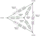
Fig. 1 is an electrical schematic diagram of a dc circuit breaker according to a first embodiment of the present invention.
Fig. 2 is an electrical schematic diagram of a second embodiment of the dc circuit breaker according to the present invention.
Detailed Description
The preferred embodiments of the present invention will be described in detail below with reference to the accompanying drawings: it should be understood that the preferred embodiments are illustrative of the invention only and are not limiting upon the scope of the invention.
First embodiment of the dc breaker:
as shown in fig. 1, when there are three outlet terminals of the dc circuit breaker, the dc circuit breaker includes three on-state current branches and three main breaker branches.
The three on-state current branches are formed by connecting a rapid mechanical switch (FSD) and an auxiliary converter module (ASM) in series; the number of the fast mechanical switches FSD is at least one; the number of the auxiliary commutation modules ASM is at least one. The on-state current branch 12 is connected between the outlet terminal 1 and the outlet terminal 2; the on-state current branch 23 is connected between the outlet terminal 2 and the outlet terminal 3; the on-state current branch 31 is connected between the outlet terminal 3 and the outlet terminal 1. When the rated voltage of the direct current circuit breaker is 500kV, the rated voltage of each on-state current branch is not lower than 500 kV.
The three main breaker branches are all formed by connecting main breaker sub-modules SM in series, and each main breaker sub-module SM comprises a power electronic current-breaking unit and an energy consumption unit; the number of the main breaker sub-modules SM is at least one. One end of the main breaker branch 1 is directly connected with the wire outlet end 1, and the other end of the main breaker branch is connected with the electrical node o; one end of the main breaker branch 2 is directly connected with the wire outlet end 2, and the other end of the main breaker branch is connected with the electrical node o; one end of the main breaker branch 3 is directly connected with the outlet terminal 3, and the other end is connected with the electrical node o. When the rated voltage of the direct current circuit breaker is 500kV, the rated voltage of each main circuit breaker branch is not lower than 250 kV. The number of power electronic components, energy consumption units and other components used in each main breaker branch is half of that of the existing direct current breaker, so the cost is lower.
The embodiment provides a control method of a direct current breaker, which comprises the following processes:
when a direct-current power grid connected with the direct-current circuit breaker normally operates, the fast mechanical switches FSD of the on-state current branch 12, the on-state current branch 23 and the on-state current branch 31 are closed, the auxiliary commutation modules ASM of the on-state current branch 12, the on-state current branch 23 and the on-state current branch 31 are unlocked, and most or all direct currents flow through the on-state current branch 12, the on-state current branch 23 and the on-state current branch 31.
When a direct current breaker is used for cutting off direct current equipment connected with a leading-out terminal 1, firstly, an auxiliary commutation module ASM of an on-state current branch 12 and an on-state current branch 31 is locked, any one or two of a main breaker branch 1 and a main breaker branch 2/3 are unlocked, and currents of the on-state current branch 12 and the on-state current branch 31 are transferred to the main breaker branch; then the fast mechanical switch FSD of the on-state current branch 12 and the on-state current branch 31 is opened; and then, the main breaker branch is locked, and the direct current breaker completes the isolation of direct current equipment connected with the outlet end 1 along with the absorption of the energy consumption unit in the main breaker branch on the fault energy of the direct current system.
When the direct current power grid requires to reconnect the direct current equipment within a short time after the direct current breaker completes the isolation of the direct current equipment connected with the outlet terminal 1, firstly, any one or two of the main breaker branch 1 and the main breaker branch 2/3 are unlocked; when the direct current flowing through the main circuit breaker branch does not exceed the overcurrent protection fixed value of the direct current circuit breaker and is kept for a certain time, the fast mechanical switches FSD of the on-state current branch 12 and the on-state current branch 31 are switched on, and meanwhile, the auxiliary current conversion modules ASM of the on-state current branch 12 and the on-state current branch 31 are unlocked; after the direct current is transferred from the main breaker branch to the on-state current branch 12 and the on-state current branch 31, the re-grid connection of the direct current equipment connected with the outlet terminal 1 is realized.
When a direct current breaker is used for cutting off direct current equipment connected with a leading-out terminal 2, firstly, an auxiliary commutation module ASM of an on-state current branch circuit 12 and an on-state current branch circuit 23 is locked, any one or two of a main breaker branch circuit 2 and a main breaker branch circuit 1/3 are unlocked, and currents of the on-state current branch circuit 12 and the on-state current branch circuit 23 are transferred to the main breaker branch circuit; then the fast mechanical switch FSD of the on-state current branch 12 and the on-state current branch 23 is opened; and then the main breaker branch is locked, and the direct current breaker completes the isolation of direct current equipment connected with the outlet end 2 along with the absorption of the energy consumption unit in the main breaker branch on the fault energy of the direct current system.
When the direct current power grid requires to reconnect the direct current equipment within a short time after the direct current breaker completes the isolation of the direct current equipment connected with the outlet end 2, firstly, any one or two of the main breaker branch 2 and the main breaker branch 1/3 are unlocked; when the direct current flowing through the main circuit breaker branch does not exceed the overcurrent protection fixed value of the direct current circuit breaker and is kept for a certain time, the fast mechanical switch FSD of the on-state current branch 12 and the on-state current branch 23 is switched on, and meanwhile, the auxiliary current conversion modules ASM of the on-state current branch 12 and the on-state current branch 23 are unlocked; after the direct current is transferred from the main breaker branch to the on-state current branch 12 and the on-state current branch 23, the re-grid connection of the direct current equipment connected with the outlet end 2 is realized.
When a direct current breaker is used for cutting off direct current equipment connected with a leading-out terminal 3, firstly, an auxiliary commutation module ASM of an on-state current branch 23 and an on-state current branch 31 is locked, any one or two of a main breaker branch 3 and a main breaker branch 1/2 are unlocked, and currents of the on-state current branch 23 and the on-state current branch 31 are transferred to the main breaker branch; then the fast mechanical switch FSD of the on-state current branch 23 and the on-state current branch 31 is opened; then, the main breaker branch is locked, and the direct current breaker completes the isolation of direct current equipment connected with the outlet end 3 along with the absorption of the energy consumption unit in the main breaker branch on the fault energy of the direct current system.
When the direct current power grid requires to reconnect the direct current equipment within a short time after the direct current breaker completes the isolation of the direct current equipment connected with the outlet end 3, firstly, any one or two of the main breaker branch 3 and the main breaker branch 1/2 are unlocked; when the direct current flowing through the main circuit breaker branch does not exceed the overcurrent protection fixed value of the direct current circuit breaker and is kept for a certain time, the fast mechanical switches FSD of the on-state current branch 23 and the on-state current branch 31 are switched on, and meanwhile, the auxiliary current conversion modules ASM of the on-state current branch 23 and the on-state current branch 31 are unlocked; after the direct current is transferred from the main breaker branch to the on-state current branch 23 and the on-state current branch 31, the re-grid connection of the direct current equipment connected with the outlet terminal 3 is realized.
Second embodiment of the dc breaker:
as shown in fig. 2, when the number of the outlet terminals of the dc circuit breaker is four, the dc circuit breaker includes four on-state current branches and four main breaker branches.
The four on-state current branches are formed by connecting a rapid mechanical switch (FSD) and an auxiliary converter module (ASM) in series; the number of the fast mechanical switches FSD is at least one; the number of the auxiliary commutation modules ASM is at least one. The on-state current branch 12 is connected between the outlet terminal 1 and the outlet terminal 2; the on-state current branch 23 is connected between the outlet terminal 2 and the outlet terminal 3; the on-state current branch 34 is connected between the outlet terminal 3 and the outlet terminal 4; the on-state current branch 41 is connected between the outlet terminal 4 and the outlet terminal 1. When the rated voltage of the direct current circuit breaker is 500kV, the rated voltage of each on-state current branch is not lower than 500 kV.
The four main breaker branches are all formed by connecting main breaker sub-modules SM in series, and each main breaker sub-module SM comprises a power electronic current-breaking unit and an energy consumption unit; the number of the main breaker sub-modules SM is at least one. One end of the main breaker branch 1 is directly connected with the wire outlet end 1, and the other end of the main breaker branch is connected with the electrical node o; one end of the main breaker branch 2 is directly connected with the wire outlet end 2, and the other end of the main breaker branch is connected with the electrical node o; one end of the main breaker branch 3 is directly connected with the wire outlet end 3, and the other end of the main breaker branch is connected with the electrical node o; one end of the main breaker branch 4 is directly connected with the outlet terminal 4, and the other end is connected to the electrical node o. When the rated voltage of the direct current circuit breaker is 500kV, the rated voltage of each main circuit breaker branch is not lower than 250kV, and the number of power electronic components, energy consumption units and other components used in each main circuit breaker branch is half of that of the existing direct current circuit breaker, so that the cost is lower.
The embodiment provides a control method of a direct current breaker, which comprises the following processes:
when a direct-current power grid connected with the direct-current circuit breaker normally operates, the fast mechanical switches FSD of the on-state current branch 12, the on-state current branch 23, the on-state current branch 34 and the on-state current branch 41 are closed, the auxiliary commutation modules ASM of the on-state current branch 12, the on-state current branch 23, the on-state current branch 34 and the on-state current branch 41 are unlocked, and most or all direct currents flow through the on-state current branch 12, the on-state current branch 23, the on-state current branch 34 and the on-state current branch 41.
When a direct current breaker is used for cutting off direct current equipment connected with a leading-out terminal 1, firstly, an auxiliary commutation module ASM of an on-state current branch 12 and an on-state current branch 41 is locked, any one, two or three of a main breaker branch 1 and a main breaker branch 2/3/4 are unlocked, and currents of the on-state current branch 12 and the on-state current branch 41 are transferred to the main breaker branch; then the fast mechanical switch FSD of the on-state current branch 12 and the on-state current branch 41 is opened; and then, the main breaker branch is locked, and the direct current breaker completes the isolation of direct current equipment connected with the outlet end 1 along with the absorption of the energy consumption unit in the main breaker branch on the fault energy of the direct current system.
When the direct current power grid requires to reconnect the direct current equipment within a short time after the direct current breaker completes the isolation of the direct current equipment connected with the outlet terminal 1, firstly, any one, two or three of the main breaker branch 1 and the main breaker branch 2/3/4 are unlocked; when the direct current flowing through the main circuit breaker branch does not exceed the overcurrent protection fixed value of the direct current circuit breaker and is kept for a certain time, the fast mechanical switches FSD of the on-state current branch 12 and the on-state current branch 41 are switched on, and meanwhile, the auxiliary current conversion modules ASM of the on-state current branch 12 and the on-state current branch 41 are unlocked; when the direct current is transferred from the main breaker branch to the on-state current branch 12 and the on-state current branch 41, the re-grid connection of the direct current equipment connected with the outlet terminal 1 is realized.
When a direct current breaker is used for cutting off direct current equipment connected with a leading-out terminal 2, firstly, an auxiliary commutation module ASM of an on-state current branch 12 and an on-state current branch 23 is locked, any one, two or three of a main breaker branch 2 and a main breaker branch 1/3/4 are unlocked, and currents of the on-state current branch 12 and the on-state current branch 23 are transferred to the main breaker branch; then the fast mechanical switch FSD of the on-state current branch 12 and the on-state current branch 23 is opened; and then the main breaker branch is locked, and the direct current breaker completes the isolation of direct current equipment connected with the outlet end 2 along with the absorption of the energy consumption unit in the main breaker branch on the fault energy of the direct current system.
When the direct current power grid requires to reconnect the direct current equipment within a short time after the direct current breaker completes the isolation of the direct current equipment connected with the outlet end 2, firstly, any one, two or three of the main breaker branch 2 and the main breaker branch 1/3/4 are unlocked; when the direct current flowing through the main circuit breaker branch does not exceed the overcurrent protection fixed value of the direct current circuit breaker and is kept for a certain time, the fast mechanical switch FSD of the on-state current branch 12 and the on-state current branch 23 is switched on, and meanwhile, the auxiliary current conversion modules ASM of the on-state current branch 12 and the on-state current branch 23 are unlocked; after the direct current is transferred from the main breaker branch to the on-state current branch 12 and the on-state current branch 23, the re-grid connection of the direct current equipment connected with the outlet end 2 is realized.
When a direct current breaker is used for cutting off direct current equipment connected with a wire outlet end 3, firstly, an auxiliary commutation module ASM of an on-state current branch 23 and an on-state current branch 34 is locked, any one, two or three of a main breaker branch 3 and a main breaker branch 1/2/4 are unlocked, and currents of the on-state current branch 23 and the on-state current branch 34 are transferred to the main breaker branch; then the fast mechanical switch FSD of the on-state current branch 23 and the on-state current branch 34 is opened; then, the main breaker branch is locked, and the direct current breaker completes the isolation of direct current equipment connected with the outlet end 3 along with the absorption of the energy consumption unit in the main breaker branch on the fault energy of the direct current system.
When the direct current power grid requires to reconnect the direct current equipment within a short time after the direct current breaker completes the isolation of the direct current equipment connected with the outlet end 3, firstly, any one, two or three of the main breaker branch 3 and the main breaker branch 1/2/4 are unlocked; when the direct current flowing through the main circuit breaker branch circuit does not exceed the overcurrent protection fixed value of the direct current circuit breaker and is kept for a certain time, the fast mechanical switches FSD of the on-state current branch circuit 23 and the on-state current branch circuit 34 are switched on, and meanwhile, the auxiliary current conversion modules ASM of the on-state current branch circuit 23 and the on-state current branch circuit 34 are unlocked; when the direct current is transferred from the main breaker branch to the on-state current branch 23 and the on-state current branch 34, the re-grid connection of the direct current equipment connected with the outlet terminal 3 is realized.
When a direct current breaker is used for cutting off direct current equipment connected with an outlet terminal 4, firstly, the auxiliary commutation modules ASM of the on-state current branch 34 and the on-state current branch 41 are locked, any one, two or three of the main breaker branch 4 and the main breaker branch 1/2/3 are unlocked, and the currents of the on-state current branch 34 and the on-state current branch 41 are transferred to the main breaker branch; then the fast mechanical switch FSD of the on-state current branch 34 and the on-state current branch 41 is opened; and then the main breaker branch is locked, and the direct current breaker completes the isolation of direct current equipment connected with the outlet end 4 along with the absorption of the energy consumption unit in the main breaker branch on the fault energy of the direct current system.
When the direct current power grid requires to reconnect the direct current equipment within a short time after the direct current breaker completes the isolation of the direct current equipment connected with the outlet terminal 4, firstly, any one, two or three of the main breaker branch circuit 4 and the main breaker branch circuit 1/2/3 are unlocked; when the direct current flowing through the main breaker branch does not exceed the overcurrent protection fixed value of the direct current breaker and is kept for a certain time, the fast mechanical switches FSD of the on-state current branch 34 and the on-state current branch 41 are switched on, and meanwhile, the auxiliary current conversion modules ASM of the on-state current branch 34 and the on-state current branch 41 are unlocked; when the direct current is transferred from the main breaker branch to the on-state current branch 34 and the on-state current branch 41, the re-grid connection of the direct current equipment connected with the outlet terminal 4 is realized.
Although the present invention has been described in detail with reference to the above embodiments, those skilled in the art can modify and substitute specific embodiments of the present invention without departing from the scope of the claims of the present invention. For example, embodiments of the dc circuit breaker of the present invention provided for interconnecting 5 and more dc devices of a dc grid can be easily envisaged.
Claims (2)
1. A direct current breaker is characterized by comprising N line-out ends, N is more than or equal to 3, N on-state current branches and N main breaker branches;
the outlet end is directly connected with the two on-state current branches and one main breaker branch;
two ends of the on-state current branch are respectively and directly connected with two adjacent outlet ends of the direct current circuit breaker;
one end of the main breaker branch is directly connected with the wire outlet end of the direct current breaker, and the other end of the main breaker branch is connected with other main breaker branches at an electrical node (o).
2. The dc circuit breaker of claim 1, wherein the main breaker branch has a voltage rating not less than half of the dc circuit breaker voltage rating.
Priority Applications (2)
| Application Number | Priority Date | Filing Date | Title |
|---|---|---|---|
| CN201710144624.4A CN106848999B (en) | 2017-03-13 | 2017-03-13 | Direct current breaker |
| PCT/CN2017/079689 WO2018166005A1 (en) | 2017-03-13 | 2017-04-07 | Direct-current circuit breaker |
Applications Claiming Priority (1)
| Application Number | Priority Date | Filing Date | Title |
|---|---|---|---|
| CN201710144624.4A CN106848999B (en) | 2017-03-13 | 2017-03-13 | Direct current breaker |
Publications (2)
| Publication Number | Publication Date |
|---|---|
| CN106848999A CN106848999A (en) | 2017-06-13 |
| CN106848999B true CN106848999B (en) | 2020-02-28 |
Family
ID=59143382
Family Applications (1)
| Application Number | Title | Priority Date | Filing Date |
|---|---|---|---|
| CN201710144624.4A Active CN106848999B (en) | 2017-03-13 | 2017-03-13 | Direct current breaker |
Country Status (1)
| Country | Link |
|---|---|
| CN (1) | CN106848999B (en) |
Families Citing this family (2)
| Publication number | Priority date | Publication date | Assignee | Title |
|---|---|---|---|---|
| EP3540750B1 (en) * | 2018-03-16 | 2021-05-05 | ABB Power Grids Switzerland AG | Hvdc circuit breaker, hvdc switchyard, hvdc switchyard system, and hvdc grid |
| CN108599099B (en) * | 2018-04-26 | 2019-09-10 | 中国科学院电工研究所 | A kind of multi-line dc circuit breaker and cutoff method |
Citations (5)
| Publication number | Priority date | Publication date | Assignee | Title |
|---|---|---|---|---|
| JP2014112984A (en) * | 2012-12-05 | 2014-06-19 | Hitachi Ltd | Dc power transmission control system |
| EP2887483A1 (en) * | 2013-12-18 | 2015-06-24 | PWM Drives Limited | Breaker circuit configurations for multi-terminal DC systems |
| CN106253066A (en) * | 2016-08-18 | 2016-12-21 | 平高集团有限公司 | A kind of dc switch station |
| CN106301307A (en) * | 2016-10-13 | 2017-01-04 | 全球能源互联网研究院 | A kind of New Cascading full-bridge high voltage DC breaker and control method thereof |
| CN206806977U (en) * | 2017-03-13 | 2017-12-26 | 康成 | A kind of dc circuit breaker |
-
2017
- 2017-03-13 CN CN201710144624.4A patent/CN106848999B/en active Active
Patent Citations (5)
| Publication number | Priority date | Publication date | Assignee | Title |
|---|---|---|---|---|
| JP2014112984A (en) * | 2012-12-05 | 2014-06-19 | Hitachi Ltd | Dc power transmission control system |
| EP2887483A1 (en) * | 2013-12-18 | 2015-06-24 | PWM Drives Limited | Breaker circuit configurations for multi-terminal DC systems |
| CN106253066A (en) * | 2016-08-18 | 2016-12-21 | 平高集团有限公司 | A kind of dc switch station |
| CN106301307A (en) * | 2016-10-13 | 2017-01-04 | 全球能源互联网研究院 | A kind of New Cascading full-bridge high voltage DC breaker and control method thereof |
| CN206806977U (en) * | 2017-03-13 | 2017-12-26 | 康成 | A kind of dc circuit breaker |
Also Published As
| Publication number | Publication date |
|---|---|
| CN106848999A (en) | 2017-06-13 |
Similar Documents
| Publication | Publication Date | Title |
|---|---|---|
| US10756535B2 (en) | Combined direct current circuit breaker and application method thereof | |
| US11322926B2 (en) | Hybrid DC circuit breaker | |
| US9000623B2 (en) | Using the transfer switch of a hybrid circuit breaker as selector switch | |
| EP3267460B1 (en) | Direct-current interruption device | |
| Li et al. | Frontiers of DC circuit breakers in HVDC and MVDC systems | |
| RU2592640C2 (en) | Linear dc voltage protective automatic device | |
| He et al. | A high-performance and economical multiport hybrid direct current circuit breaker | |
| US20130271888A1 (en) | Photovoltaic System and Apparatus for Operating a Photovoltaic System | |
| US20170331281A1 (en) | Dc electrical network | |
| CN111509682B (en) | Hybrid direct current circuit breaker sharing main through-current branch and protection device and method thereof | |
| CN112865040A (en) | Multi-port direct current circuit breaker and control method thereof | |
| CN106848999B (en) | Direct current breaker | |
| US9837224B2 (en) | Switchgear assembly | |
| US9893520B2 (en) | Switching device | |
| US20190013674A1 (en) | Electrical assembly | |
| CN114597872B (en) | DC circuit breaker, control method thereof and electronic equipment | |
| CN210201475U (en) | Controllable type multiport direct current circuit breaker of direct current electric wire netting trend | |
| Kunde et al. | Integration of fast acting electronic fault current limiters (EFCL) in medium voltage systems | |
| WO2018032643A1 (en) | Direct current switching station | |
| CN114726228A (en) | Solid-state transformer and power supply equipment | |
| CN112838576A (en) | Direct current breaker and application method thereof | |
| WO2013091699A1 (en) | An arrangement for controlling the electric power transmission in a hvdc power transmission system | |
| Etxegarai et al. | HVDC circuit breakers for HVDC grids | |
| WO2018166005A1 (en) | Direct-current circuit breaker | |
| CN116783677A (en) | DC circuit breaker |
Legal Events
| Date | Code | Title | Description |
|---|---|---|---|
| PB01 | Publication | ||
| PB01 | Publication | ||
| SE01 | Entry into force of request for substantive examination | ||
| SE01 | Entry into force of request for substantive examination | ||
| GR01 | Patent grant | ||
| GR01 | Patent grant |