CN1068211A - The storing utensil of tape cassete - Google Patents
The storing utensil of tape cassete Download PDFInfo
- Publication number
- CN1068211A CN1068211A CN92104919A CN92104919A CN1068211A CN 1068211 A CN1068211 A CN 1068211A CN 92104919 A CN92104919 A CN 92104919A CN 92104919 A CN92104919 A CN 92104919A CN 1068211 A CN1068211 A CN 1068211A
- Authority
- CN
- China
- Prior art keywords
- utensil
- transfer member
- tape
- locking
- tep reel
- Prior art date
- Legal status (The legal status is an assumption and is not a legal conclusion. Google has not performed a legal analysis and makes no representation as to the accuracy of the status listed.)
- Pending
Links
- 238000003780 insertion Methods 0.000 claims abstract description 3
- 230000037431 insertion Effects 0.000 claims abstract description 3
- 238000012546 transfer Methods 0.000 claims description 67
- 238000006073 displacement reaction Methods 0.000 claims description 6
- 230000002153 concerted effect Effects 0.000 claims description 5
- 238000000151 deposition Methods 0.000 claims description 3
- 238000006243 chemical reaction Methods 0.000 claims description 2
- 239000002984 plastic foam Substances 0.000 claims description 2
- 230000008485 antagonism Effects 0.000 claims 1
- 238000013461 design Methods 0.000 abstract description 4
- 238000007634 remodeling Methods 0.000 description 3
- 240000008415 Lactuca sativa Species 0.000 description 2
- 241000278713 Theora Species 0.000 description 2
- 238000005452 bending Methods 0.000 description 2
- 239000004033 plastic Substances 0.000 description 2
- 235000012045 salad Nutrition 0.000 description 2
- 238000004458 analytical method Methods 0.000 description 1
- 230000006835 compression Effects 0.000 description 1
- 238000007906 compression Methods 0.000 description 1
- RKTYLMNFRDHKIL-UHFFFAOYSA-N copper;5,10,15,20-tetraphenylporphyrin-22,24-diide Chemical group [Cu+2].C1=CC(C(=C2C=CC([N-]2)=C(C=2C=CC=CC=2)C=2C=CC(N=2)=C(C=2C=CC=CC=2)C2=CC=C3[N-]2)C=2C=CC=CC=2)=NC1=C3C1=CC=CC=C1 RKTYLMNFRDHKIL-UHFFFAOYSA-N 0.000 description 1
- 238000000280 densification Methods 0.000 description 1
- 238000010586 diagram Methods 0.000 description 1
- 239000000428 dust Substances 0.000 description 1
- 230000000694 effects Effects 0.000 description 1
- 238000012856 packing Methods 0.000 description 1
- 239000012858 resilient material Substances 0.000 description 1
Images


Classifications
-
- G—PHYSICS
- G11—INFORMATION STORAGE
- G11B—INFORMATION STORAGE BASED ON RELATIVE MOVEMENT BETWEEN RECORD CARRIER AND TRANSDUCER
- G11B23/00—Record carriers not specific to the method of recording or reproducing; Accessories, e.g. containers, specially adapted for co-operation with the recording or reproducing apparatus ; Intermediate mediums; Apparatus or processes specially adapted for their manufacture
- G11B23/02—Containers; Storing means both adapted to cooperate with the recording or reproducing means
- G11B23/023—Containers for magazines or cassettes
- G11B23/0233—Containers for a single cassette
Abstract
Be suitable for admitting the storing utensil of the tape cassete of different designs specification, that is, this storing utensil both can have been deposited the fine and close box of standard, can deposit the digital recording tape drum again.When the fine and close box of insertion standard, the tep reel Lock Part is activated, and when inserting the digital recording box, it is motionless that the tape drum Lock Part keeps.
Description
The present invention relates to a kind of storing utensil of tape cassete, promptly a kind of storing utensil based on the mentioned tape cassete of US patent 3,899,229, in other words, be the US patent 4,702,372 or 4 that the application is quoted as proof, 738,361 or 4,828, the improvement of 341 announcement utensils.
These above-mentioned conventional appliances comprise a shell and a conveyer that leads slidably and be suitable for transporting tape drum in described shell.This transport carriage be spring deflection one open or extracting position and can be in shell at the deposit position breech lock.
These known utensils are to design for holding known standard densification (compact) tape drum, and this tape drum can freely contact tep reel.For example, in vehicle, deposit and when being subject to vibrate, tape cassete just has the danger of bearing improper rotation, thus make tape drum may since what is called " band salad " (tape salad) be damaged.Therefore, these known storing utensils all are equipped with the closed block that constitutes one with carriage, so that embed and pin tep reel.
Recent a kind of called after " DCC ", or claim the novel tape drum of digital recording tape drum to emerge.The reproduction quality of this tape is better than writing down the traditional fine and close tape of simulating signal, the register of being developed for this DCC tape information of the DCC tape traditional cassette information of also resetting of can not only resetting.Therefore, this tape appearance of two types is very similar.But, following 2 significantly differences are arranged: the fine and close tape of standard is tetragonal protuberance by the surface of that end of magnetic head, and the DCC box does not have this protuberance.In addition, the DCC box disposes and makes tep reel avoid the valve that dust is invaded; At ordinary times, tep reel is locked in the tape drum, only when packing tape drum into reproducing device, just removes valve, exposes tep reel.
Certainly, traditional tape storing utensil is unsuitable for deposits the DCC tape, because the cause of its tep reel Lock Part must design a kind of utensil that holds the DCC box that is exclusively used in.But, because reproducing device can be used for this two classes tape, and for a certain specific people, also may not necessarily give and know and necessarily like any tape, therefore, be necessary to provide a kind of tape drum storing utensil that is suitable for holding any tape.
Purpose of the present invention is provides the tape drum storing utensil that is suitable for holding any tape.
According to the utensil of depositing tape cassete provided by the present invention, comprising: roughly be first case member of parallelepiped-shaped, which is provided with an opening; Can be by the tape drum transfer member of described opening with respect to described first part displacements, described two parts are in a tape of deposit position fully around being carried by described transfer member, and when described transfer member was in moving position, described two parts made tape replaceable; With the catapult-launching gear of described two parts concerted actions, use so that described two parts are setovered to described moving position; The locking device that can get loose is in order to be fixed in described two parts and the opposite deposit position of described catapult-launching gear biased direction; Being arranged in one of described parts and can embedding can be from the locking member in the tep reel of outside contact, and described locking member makes when depositing the tape that its tep reel can not contact from the outside stiff.
Tape cassete container provided by the present invention also can be following structure, promptly comprises:
Be roughly the case member of parallelepipedon and a box that is contained in the transfer member of guiding in the described case member, can be convenient to the moving position that inserts and take out so that a tape is sent to from its deposit position that is closed in described case member; Comprise that also the described transfer member of biasing is in the catapult-launching gear of described moving position; Also comprise: the manual locking device that can get loose, in order to fixing described transfer member in described deposit position; And also comprise locking member, these parts are contained in one of described shell and transfer member movably, in order to can be when the outside contacts when tape reel, fixedly be inserted into the tep reel of tape drum, when described transfer member when described moving position is shifted to described deposit position, described locking member just engages with the control assembly on another of described shell and transfer member effectively, and when an impalpable tape of its tep reel was put into this transfer member, described effective joint just was disconnected.
Be used to deposit the utensil of tape cassete, also can be following form, promptly comprise a case member that is roughly parallelepipedon and a box that is contained in the transfer member of guiding in the described case member, can be convenient to the moving position that inserts and take out so that a tape drum is sent to from its deposit position that is closed in described case member; Comprise that also the described transfer member of biasing is in the catapult-launching gear of described moving position; Also comprise the locking device that manually can get loose, in order to fix described transfer member in described deposit position; And the locking member that also comprises removable setting, inserted the tep reel of tape drum in order to locking, this tape drum be provided with can outside contact tep reel hole and head side convex surface part, described locking member then activated because of described convex surface part, and when described transfer member with tape drum when not having this convex surface part, just keep motionless.
Some most preferred embodiments of the above-mentioned utensil of the present invention can be listed below: they also can comprise an elastic device, in order to the bounce between slotting box of compensation quilt and the transfer member; This elastic device can constitute the part of locking member bias spring, also can comprise a plastic foam pad; Locking member can pivot.This utensil also can comprise the compensation system in order to the difference of the thickness that compensates different cassette bays.Other feature can be: in case when tape drum was placed on the transfer member, described locking member was bootable; In case or transfer member from described extracting position when the described deposit position displacement, locking member is bootable; Described locking member is arranged on the transfer member and case member has in order to handle the stop motion mechanism of locking member, also comprises the elastic device between at least one pair of following elements; Case member/stop motion mechanism; Stop motion mechanism/locking member; Locking member/transfer member, transfer member/tape drum.
The another kind of form of implementation of utensil of the present invention can be: comprise a case member that roughly is parallelepipedon; With a box that holds transfer member; This transfer member in described case member, lead movablely in case with a box from its be closed in deposit position in the described case member be sent to described box can be by the movable position of inserting easily and taking out, this utensil comprises that also one is used to make described transfer member to be partial to the spring assembly of described movable position, the locking device that manually can get loose, in order to transfer member is fixed in described deposit position, with the locking device that is used to lock the tep reel that is inserted into box that on described transfer member, disposes, the control of the slotting box of quilt of the tep reel that can freely contact is installed movablely and be subjected to having to this device when described transfer member is in described deposit position, and present primary importance, make described device embed described dish, thereby locking tep reel, the quilt that has a unreachable tep reel is inserted box and is then controlled described device when described transfer member is in described deposit position, goes to present by this box second place in addition that taken up space.
Some most preferred embodiment characteristics of this utensil are: its locking device rotor is contained on the transfer member rotatably, and can be the axle rotation of horizontal expansion with respect to the transfer member direction of displacement around one, or this locking device tiltably is installed in the transfer member.Described locking device also can be subjected to the control of spring force, or is controlled by a control element in the case member.This utensil also can comprise two locking devices, place with respect to the single line of transfer member moving direction horizontal expansion each on one side, or tandem is set up before and after being with respect to the transfer member moving direction.The locking device of this utensil, can be configured to not during case at transfer member; Have can not the contact tep reel time with a control element concerted action set on the case member and inserting one, locking device can do to be different from the deflection in concerted action path.The tep reel that this locking device can be in moving position together is engaged with each other; Or the tep reel of the moving position that exists together is frictionally engaged; Or force tep reel to go to overcome any resistance between tep reel and the box shell.
Now in conjunction with the accompanying drawings, describe several embodiments of the present invention in detail.
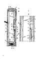
Fig. 1 is a sectional view of the utensil of the present invention that the 1-1 line is intercepted among Fig. 2;
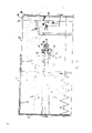
Fig. 2 is the part plan view of utensil shown in Figure 1, and wherein shell is analysed and observe, and transfer member is shown in an open position;
Fig. 3 is similar to Fig. 1, just has a fine and close tape drum that is inserted into;
Fig. 4 shows the position that deposit position inserts locking member and control element before the fine and close tape;
Fig. 5 is the key diagram of a similar deposit position;
Fig. 6 illustrate with fine and close tape when the deposit position locking member and the concerted action of control element;
Fig. 7 is similar to Fig. 3, and what just insert is the DCC tape;
Fig. 8 to 10 is similar to Fig. 4 to 6, and what just insert is the DCC tape;
Figure 11 to 14 shows the cut-open view of locking member, side view, plan view and front view respectively with the ratio of having amplified;
Figure 15 is the plan view that has a kind of utensil remodeling that shell analyses and observe, and its transfer member is shown in an open position, and does not also insert tape drum simultaneously, and
Figure 16 is the phantom view according to a kind of utensil of the present invention, and this utensil has the remodeling control device of a locking member.
It is to be noted at first how many all accompanying drawings are simplified through a little, with outstanding key property of the present invention.Those are not that basic details can obtain from above mentioned open source literature to the present invention.
The first embodiment of the present invention now is described, described container or claim storing utensil to comprise a shell 20 that forms by plastic mo(u)lding, one also forms slider 22 as transfer member by plastic injected die, and place spiral compression spring 24 between housing back wall 26 and the slider rear wall 28, so that slider deflection extracting position as shown.Slider is guided in the enclosure along its length.Its outer end, that is, extracting position is by limiting with the whole block 30 that forms and embed outer casing bottom groove 32 of slider.At this utensil deposit position as shown in Figure 5, embedding an outer casing groove by a lock bar element 34 can pin slider or fasten and just can unblank by manually operated pin 36.Antetheca 40 at slider is provided with one as the sensing element 38 that fills up indicator.So far described utensil characteristic is the known features in the prior art.
This of prior art kind of container has and slider mold all-in-one-piece tep reel locking member, when holding a tape in the convenient utensil, removes to lock tep reel; The locking member that then has rotor rotation on slider according to the utensil of first embodiment of the invention.When being placed on a tape on the slider, type that just can this box of sensing; If what deposit is fine and close tape, then make locking member at least when slider moves into its deposit position, present bonding station with respect to tep reel.Otherwise, be the DCC tape if place on the slider, then make locking member take an off-position.
In the embodiment of Fig. 1 to 15, itself has served as sensor locking member.Each locking member comprises two bearing pins 42 in each groove that will snap in the slider bottom, control projection 44(has only one in Figure 15, and in Fig. 1 to 14, have two that are symmetrical structure) locking surface 48 in spring travel limitor 46 and the Zheng Chu working position, cathode edge heads on the tooth of tep reel.
In Fig. 1 to 15 illustrated embodiment, each locking member utilization is installed in the sheet spring 50 on the slider shown in Figure 1 bottom and deflects from the spare space.One of two far-ends of sheet spring, that is, end 52 rests on two limiters 46.On being placed on slider be fine and close tape (Fig. 3) time, locking member partly stretches into the tape hole that can reach the tep reel opening, thereby makes the locking member can not deflection.When slider is pushed into shell and during homing, control projection 44 is run into the ora terminalis 54 with the Unitarily molded control rib 58 of outer casing bottom; In the embodiment of Fig. 1 to 14, be shown with a pair of this rib that is symmetrical structure.The engagement of projection 44 and ora terminalis 54 can engage locking member around its bearing pin rotation with the tep reel inside surface up to locking surface.Otherwise, be the DCC box if be placed on the slider, then because the hole that the DCC box does not have locking member to stretch into rotates locking member in the opposite direction.Therefore make control projection 44 get the control rib ora terminalis 54 tops the position and can not be driven, promptly; Inoperative.
Another far-end of sheet spring or free end 60 are inclined upwardly and towards the bending of slider antetheca, always move errorless thereby guaranteed to fill up indicator.In addition, this sheet spring end made tape drum have elastic force for opening when utensil pushed inward its deposit position slightly with slider, because make locking member exceed its latched position and rotate moving in slider this, thereby promoted tape drum along the slider basal sliding.
The size of shell aperture should be set at can only be earlier from the beveled end of fine and close tape drum, rather than earlier from there being that end of head side nonreentrant surface to insert this box.This restriction is necessary, because the center of tep reel is a symmetrical arrangements.Below fixator rib 64 is Unitarily molded with shell roof 62, so that the fixing DCC tape that inserts and press closer the bottom of slider.The location of these ribs 64 should make when inserting fine and close tape, and its head side convex surface of their unlikely obstruction is only.The bottom side of slider bottom has groove 66, to hold control rib 58.The ramp 70 of locking member is used for guiding this box to slide when inserting tape drum.
Embodiment illustrated in fig. 15 and difference first embodiment is: tape drum longitudinally inserts.For this reason, each locking member has only a control projection, and the length of respectively controlling rib differs.
What substitute spring free end 60 is the pad of being made by resilient material 72, and this pad is best to be made by polyfoam.Be noted that, for producing necessary knock-on, also have several selection schemes, locking member itself or its bearing pin can be resilient, the ora terminalis of control rib can be flexible, slider can be subjected to elastic reaction and bending near the groove that is engaged by bearing pin: in the film and television system that is considered, provide some retractilities.
In the embodiment shown in Fig. 1 to 15, whether the existence of tep reel contact hole has been carried out sensing, and be in embodiment illustrated in fig. 16 whether existing the head side convex surface of fine and close tape to carry out sensing.
One groove 80 is arranged at the slider bottom, and its shape and size are can hold the head side convex surface degree of being on the fine and close box bottom side.Sensing handle 82 stretches into this groove and because of the convex surface effect, overcomes spring biasing (not shown) and deflection.This deflection is sent to the locking member 86 that rotor rotates by connecting rod 84, selects each bar, and the brachium of handle is so that the angle that the locking member rotation is passed through is enough to pin each tep reel.Whole sensing and locking device are arranged in the slider, in case therefore put fine and close tape on the slider, its tep reel is locked immediately, and need not the facility of control rib and so on has been set on shell.
Certainly, to shown in and described all embodiment also may make many remodeling.For example, displaceable control assembly can be set on shell, simultaneously device is movably controlled rib on slider, so that according to the type of insertion tape, go to take " movable " or " not movable " position.In this class design, preferably whether the existence of head side convex surface is carried out sensing.In first embodiment, when not having tape drum on the slider, the detecting means of locking member takes " spare space or middle or half working position " can not be along either direction deflection.Otherwise the locking member among Figure 16 embodiment is taked one of two terminal position, when slider is sky, then gets off-position ".Can imagine that locking member can be designed to be in its work or keyed end position when being empty when slider, and in case when inserting the DCC tape, make the locking member can deflection.
Claims (28)
1, a kind of utensil that is used to deposit magnetic tape cassette, it comprises,
One roughly is first case member of parallel six shapes, which is provided with an opening,
One can be by the second tape transfer member of described opening with respect to described first part displacements, described two parts are in a tape of deposit position fully around being carried by described second parts, and described two parts allow tape to be replaced when described second parts are in extracting position
One with the catapult-launching gear of described two parts concerted actions, with so that described two parts setover to described extracting position,
One locking device that can get loose, in order to described two parts being fixed in the deposit position relative with the biasing of described catapult-launching gear,
One is arranged on the interior outside that also can embed of one of described parts can reach the interior locking member of tep reel, and described locking member makes when depositing its tep reel from the untouchable tape in outside stiff.
2, a kind of utensil that is used to deposit magnetic tape cassette, it comprises that one is roughly the case member of parallelepipedon and a box that is contained in the transfer member of guiding in the described case member, can be convenient to the moving position that inserts and take out so that a tape drum is sent to from its deposit position that is closed in described case member; Comprise that also the described transfer member of biasing is in the catapult-launching gear of described moving position; Also comprise: the manual locking device that can get loose, in order to fixing described transfer member in described deposit position; And also comprise locking member, these parts are contained in one of described shell and transfer member movably, in order to can be when the outside contacts when tape reel, fixedly be inserted into the tep reel of tape drum, when described transfer member when described moving position is shifted to described deposit position, described locking member just engages with the control assembly on another of described shell and transfer member effectively, and when an impalpable tape of its tep reel was put into this transfer member, described effective joint just was disconnected.
3, a kind of utensil that is used to deposit tape cassete, comprise a case member that is roughly parallelepipedon and a box that is contained in the transfer member of guiding in the described case member, can be convenient to the moving position that inserts and take out so that a tape drum is sent to from its deposit position that is closed in described case member; Comprise that also the described transfer member of biasing is in the catapult-launching gear of described moving position; Also comprise the locking device that manually can get loose, in order to fix described translator unit in described deposit position; And the locking member that also comprises removable setting, inserted the tep reel of tape drum in order to locking, this tape drum is provided with tep reel hole and the head side convex surface part that the outside can reach, described locking member then is activated because of described head side convex surface, and when described transfer member with tape drum when not having this head side convex surface, just keep motionless.
4, as utensil as described in claim 1 to 3 arbitrary, it is characterized in that: each locking member all can pivot.
5, as utensil as described in claim 1 to 4 arbitrary, it is characterized in that: each locking member is the spring bias component of deflection one predetermined direction.
6, as utensil as described in claim 1 to 5 arbitrary, it is characterized in that: also comprise an elastic device, be inserted into bounce between box and the transfer member in order to compensation.
7, described utensil as claimed in claim 6 is characterized in that: described elastic device has constituted the part of a locking member bias spring.
8, described utensil as claimed in claim 6 is characterized in that: described elastic device comprises a plastic foam pad.
9, as utensil as described in claim 1 to 8 arbitrary, its size is arranged to make the box with head side convex surface part can only described convex surface part be inserted on away from that position of inserting opening.
10, as utensil as described in claim 1 to 9 arbitrary, it is characterized in that: have other compensation system of thickness difference in order to compensate different cassette bays.
11, as utensil as described in claim 1 to 10 arbitrary, it is characterized in that: described locking member places on the described transfer member.
12, as utensil as described in claim 1 to 11 arbitrary, it is characterized in that: described locking member has and is used to guide the skid that is inserted into box.
13, as utensil as described in claim 1 to 12 arbitrary, it is characterized in that: in case when tape drum was placed on the transfer member, described locking member was mobilizable.
14, as utensil as described in claim 1 to 12 arbitrary, it is characterized in that: in case transfer member from described moving position when the described deposit position displacement, described locking member is mobilizable.
15, utensil as claimed in claim 14 is characterized in that: described locking member is arranged on the described transfer member and described case member has in order to handle the stop motion mechanism of described locking member.
16, utensil as claimed in claim 15 is characterized in that: be included in the elastic device between at least one pair of following elements:
One case member/stop motion mechanism,
One stop motion mechanism/locking member,
One locking member/transfer member,
One transfer member/tape drum.
17, a kind of utensil that is used to deposit tape cassete comprises a case member that roughly is parallelepipedon; With a box that holds transfer member; This transfer member in described case member, lead movablely in case with a box from its be closed in deposit position in the described case member be sent to described box can be by the movable position of inserting easily and taking out, this utensil comprises that also one is used to make described transfer member to be partial to the spring assembly of described movable position, the locking device that manually can get loose, in order to transfer member is fixed in described deposit position, with the locking device that is used to lock the tep reel that is inserted into box that on described transfer member, disposes, the control of the slotting box of quilt of the tep reel that can freely contact is installed movablely and be subjected to having to this device when described transfer member is in described deposit position, and present primary importance, make described device embed described dish, thereby locking tep reel, the quilt that has a unreachable tep reel is inserted box and is then controlled described device when described transfer member is in described deposit position, goes to present by this box second place outward that taken up space.
18, as utensil as described in the claim 17, it is characterized in that: described locking device rotor is contained on the described transfer member rotatably.
19, as utensil as described in the claim 18, it is characterized in that: described locking device can be around an axle rotation with respect to the direction of displacement horizontal expansion of described transfer member.
20, as utensil as described in the claim 18, it is characterized in that: described locking device tiltably is installed in the described transfer member.
21, as utensil as described in the claim 17, it is characterized in that: described locking device is subjected to the control of spring force.
22, as utensil as described in the claim 17, it is characterized in that: described locking device is controlled by a control element in the described case member.
23, utensil as claimed in claim 17 is characterized in that: comprise two described locking devices, they place each one side to the single line of the moving direction horizontal expansion of described transfer member.
24, utensil as claimed in claim 17 is characterized in that: comprise two described locking devices, they are front and back tandem configuration with respect to the moving direction of described transfer member.
25, utensil as claimed in claim 17, it is characterized in that: under the situation of described transfer member at rotatable cassette not, described locking device is configured to: match with set on a described case member control element, and when one of insertion had the tape of unreachable tep reel, described locking device can withdraw from the deflection of cooperation.
26, utensil as claimed in claim 17 is characterized in that: the described tep reel that described locking device is in moving position together is engaged with each other.
27, utensil as claimed in claim 17 is characterized in that: the described tep reel that described locking device is in moving position together is and is frictionally engaged.
28, utensil as claimed in claim 17 is characterized in that: described locking device forces described tep reel to go to overcome any antagonism reaction between described tep reel and the box shell.
Applications Claiming Priority (4)
| Application Number | Priority Date | Filing Date | Title |
|---|---|---|---|
| DE4120280 | 1991-06-19 | ||
| DEP4120280.5 | 1991-06-19 | ||
| DEP4132135.9 | 1991-09-26 | ||
| DE19914132135 DE4132135A1 (en) | 1991-09-26 | 1991-09-26 | Storage container for magnetic tape cassettes |
Publications (1)
| Publication Number | Publication Date |
|---|---|
| CN1068211A true CN1068211A (en) | 1993-01-20 |
Family
ID=25904687
Family Applications (1)
| Application Number | Title | Priority Date | Filing Date |
|---|---|---|---|
| CN92104919A Pending CN1068211A (en) | 1991-06-19 | 1992-06-19 | The storing utensil of tape cassete |
Country Status (18)
| Country | Link |
|---|---|
| US (1) | US5363960A (en) |
| EP (1) | EP0543963B1 (en) |
| JP (1) | JPH06500522A (en) |
| KR (1) | KR930701813A (en) |
| CN (1) | CN1068211A (en) |
| AT (1) | ATE161116T1 (en) |
| AU (1) | AU1922692A (en) |
| BR (1) | BR9205303A (en) |
| CA (1) | CA2089745A1 (en) |
| DE (1) | DE69223491T2 (en) |
| DK (1) | DK0543963T3 (en) |
| ES (1) | ES2112905T3 (en) |
| HU (1) | HUT64639A (en) |
| IE (1) | IE921976A1 (en) |
| NO (1) | NO930570D0 (en) |
| PL (1) | PL297651A1 (en) |
| PT (1) | PT100600A (en) |
| WO (1) | WO1992022899A1 (en) |
Families Citing this family (18)
| Publication number | Priority date | Publication date | Assignee | Title |
|---|---|---|---|---|
| EP0538585B1 (en) * | 1991-10-22 | 1997-01-02 | fischerwerke Artur Fischer GmbH & Co. KG | Magnetic tape cassette container |
| DE4219232A1 (en) * | 1992-06-12 | 1993-12-16 | Fischer Artur Werke Gmbh | Device for storing magnetic tape cassettes |
| DE4219233A1 (en) * | 1992-06-12 | 1993-12-16 | Fischer Artur Werke Gmbh | Device for storing magnetic tape cassettes |
| DE4324266A1 (en) * | 1993-07-20 | 1995-01-26 | Fischer Artur Werke Gmbh | Cassette holder with clamping device |
| US5515979A (en) * | 1994-07-05 | 1996-05-14 | Salvail; Napoleon P. | Simplified jewel case management and opening for compact disk storage systems |
| US5534836A (en) * | 1994-11-28 | 1996-07-09 | Sensormatic Electronics Corporation | Deactivator for theft-deterrent markers |
| DE19609998A1 (en) * | 1996-03-14 | 1997-09-18 | Fischer Artur Werke Gmbh | Cassette holder |
| USD384538S (en) * | 1996-04-04 | 1997-10-07 | John Bosworth | Digital video disk case |
| USD386915S (en) * | 1996-04-05 | 1997-12-02 | Sony Kabushiki Kaisha | Audio cassette tape case |
| FR2755922B1 (en) * | 1996-11-21 | 1998-12-31 | Reydel Sa | INTERIOR ARRANGEMENT FOR VEHICLE SUCH AS, FOR EXAMPLE, MOTOR VEHICLE |
| US5706943A (en) * | 1997-03-03 | 1998-01-13 | Yu; Jack | Container for cassette or the like |
| US5984093A (en) * | 1997-11-07 | 1999-11-16 | Frick Management Group Limited | Automatic storage media release mechanism for storage media package |
| US5878879A (en) * | 1998-03-13 | 1999-03-09 | Liao; Chung Kuang | Cassette holder having easily removable insert |
| US6896132B1 (en) | 2001-03-29 | 2005-05-24 | Markus W. Frick | Storage media case |
| NO315314B1 (en) * | 2001-10-12 | 2003-08-18 | Smartbox As | Device for sealable maternity |
| FR2889425B1 (en) * | 2005-08-04 | 2007-10-12 | Francois Picot | MEANS FOR TRANSPORTING A PRODUCT COMPRISING AT LEAST ONE RECTILINEED WALL, AND IN PARTICULAR A PORTABLE COMPUTER |
| CN2919349Y (en) * | 2006-04-21 | 2007-07-04 | 鸿富锦精密工业(深圳)有限公司 | Storage fixing device |
| US20080157455A1 (en) * | 2006-12-29 | 2008-07-03 | Applied Materials, Inc. | Compliant substrate holding assembly |
Family Cites Families (17)
| Publication number | Priority date | Publication date | Assignee | Title |
|---|---|---|---|---|
| NL6712753A (en) * | 1967-09-18 | 1969-03-20 | ||
| CH556589A (en) * | 1972-09-06 | 1974-11-29 | Idn Invention Dev Novelties | CONTAINER FOR ACCEPTING A CASSETTE WITH A TAPE-SHAPED RECORDING MEDIA. |
| DE2427103A1 (en) * | 1974-06-05 | 1975-12-18 | Idn Invention Dev Novelties | CONTAINER FOR STORING MAGNETIC TAPE CASSETTES |
| DE2427109A1 (en) * | 1974-06-05 | 1976-01-02 | Idn Invention Dev Novelties | CONTAINER FOR MAGNETIC TAPE CASSETTES |
| US4067629A (en) * | 1975-04-03 | 1978-01-10 | Sony Corporation | Storage receptacle for magnetic tape cassette |
| US4087145A (en) * | 1976-07-30 | 1978-05-02 | Minnesota Mining And Manufacturing Company | Magnetic tape cartridge case with biasing means |
| US4184594A (en) * | 1978-12-22 | 1980-01-22 | Hehn Bruce A | Video cassette storage container |
| DE3015749A1 (en) * | 1980-04-24 | 1981-10-29 | IDN Inventions and Development of Novelties AG, Chur | Cassette holder for use in vehicles - has lever displaced upon cassette insertion to hold tape in secured position |
| US4406369A (en) * | 1980-07-21 | 1983-09-27 | Unique Designs, A General Partnership | Tape cassette holder |
| US4322000A (en) * | 1980-08-13 | 1982-03-30 | Diamond International Corporation | Tape cassette packages and holders therefor |
| US4291801A (en) * | 1980-10-03 | 1981-09-29 | Plastic Reel Corporation Of America | Video cassette storage container |
| JPS609182Y2 (en) * | 1981-06-18 | 1985-04-02 | アルファレコ−ド株式会社 | cassette tape case magazine |
| DE3215721A1 (en) * | 1982-04-28 | 1983-11-03 | IDN Inventions and Development of Novelties AG, 7002 Chur | MAGNETIC TAPE CONTAINER |
| EP0134279A1 (en) * | 1983-08-29 | 1985-03-20 | idn inventions and development of novelties ag | Storage container for magnetic tape cassettes |
| DE8416751U1 (en) * | 1984-06-01 | 1985-09-26 | IDN Inventions and Development of Novelties AG, Chur | Device for storing recording media, in particular for installation in motor vehicles |
| JPS6355082A (en) * | 1986-04-18 | 1988-03-09 | 瀬川 朝史 | Cassette case |
| DE3904787A1 (en) * | 1989-02-17 | 1990-08-23 | Fischer Artur Werke Gmbh | CONTAINER WITH MAGNETIC TAPE CASSETTE |
-
1992
- 1992-06-03 JP JP4511225A patent/JPH06500522A/en active Pending
- 1992-06-03 EP EP92911296A patent/EP0543963B1/en not_active Expired - Lifetime
- 1992-06-03 WO PCT/EP1992/001226 patent/WO1992022899A1/en active IP Right Grant
- 1992-06-03 DK DK92911296T patent/DK0543963T3/en active
- 1992-06-03 AU AU19226/92A patent/AU1922692A/en not_active Abandoned
- 1992-06-03 BR BR9205303A patent/BR9205303A/en not_active Application Discontinuation
- 1992-06-03 US US07/988,124 patent/US5363960A/en not_active Expired - Fee Related
- 1992-06-03 HU HU9300346A patent/HUT64639A/en unknown
- 1992-06-03 AT AT92911296T patent/ATE161116T1/en not_active IP Right Cessation
- 1992-06-03 PL PL29765192A patent/PL297651A1/en unknown
- 1992-06-03 ES ES92911296T patent/ES2112905T3/en not_active Expired - Lifetime
- 1992-06-03 CA CA002089745A patent/CA2089745A1/en not_active Abandoned
- 1992-06-03 DE DE69223491T patent/DE69223491T2/en not_active Expired - Fee Related
- 1992-06-17 PT PT100600A patent/PT100600A/en not_active Application Discontinuation
- 1992-06-19 CN CN92104919A patent/CN1068211A/en active Pending
- 1992-07-01 IE IE197692A patent/IE921976A1/en not_active Application Discontinuation
-
1993
- 1993-02-18 KR KR1019930700464A patent/KR930701813A/en active IP Right Grant
- 1993-02-18 NO NO930570A patent/NO930570D0/en unknown
Also Published As
| Publication number | Publication date |
|---|---|
| BR9205303A (en) | 1994-06-14 |
| JPH06500522A (en) | 1994-01-20 |
| ES2112905T3 (en) | 1998-04-16 |
| HUT64639A (en) | 1994-01-28 |
| NO930570L (en) | 1993-02-18 |
| WO1992022899A1 (en) | 1992-12-23 |
| PT100600A (en) | 1994-05-31 |
| HU9300346D0 (en) | 1993-05-28 |
| NO930570D0 (en) | 1993-02-18 |
| CA2089745A1 (en) | 1992-12-20 |
| DE69223491D1 (en) | 1998-01-22 |
| ATE161116T1 (en) | 1997-12-15 |
| DE69223491T2 (en) | 1998-05-07 |
| KR930701813A (en) | 1993-06-12 |
| IE921976A1 (en) | 1992-12-30 |
| EP0543963A1 (en) | 1993-06-02 |
| AU1922692A (en) | 1993-01-12 |
| US5363960A (en) | 1994-11-15 |
| DK0543963T3 (en) | 1998-08-24 |
| PL297651A1 (en) | 1993-11-15 |
| EP0543963B1 (en) | 1997-12-10 |
Similar Documents
| Publication | Publication Date | Title |
|---|---|---|
| CN1068211A (en) | The storing utensil of tape cassete | |
| KR900008096B1 (en) | Tape cassette | |
| US4640415A (en) | Container having automatic doors and for accommodating data storage media | |
| US5285897A (en) | Tape cassette case | |
| US3867722A (en) | Cassette eject mechanism | |
| US4682319A (en) | Pivoting front cover for a drawer | |
| US4017900A (en) | Tape recorder cassette ejecting device | |
| EP0393647A3 (en) | Portable recording and/or reproducing apparatus | |
| US4768116A (en) | Device for automatically changing magnetic disc pack | |
| GB2236208A (en) | Disk driving apparatus | |
| EP1079323A2 (en) | Transfer apparatus | |
| US5999364A (en) | Cassette mounting and ejection mechanism | |
| JPH064950A (en) | Cassette housing mechanism in acoustic equipment | |
| EP0628962B1 (en) | Cassette tape player having cassette guide | |
| US5132862A (en) | Erasure preventing button with a planar surface to control inadvertent sliding for tape cassettes | |
| EP0790610B1 (en) | Cassette loading device | |
| US5381897A (en) | Device for storing magnetic tape cassettes | |
| GB2093628A (en) | Disc record player | |
| US5598925A (en) | Holder for a sound recording medium housing having rattling noise prevention means | |
| US7035109B2 (en) | Recording media unit | |
| US5390056A (en) | Recording/reproducing apparatus capable of accepting tape cartridges of different sizes | |
| US4368370A (en) | Switch actuating apparatus for video disc player | |
| EP0323576B1 (en) | Tape cassette loading mechanism in tape player | |
| US5442501A (en) | Device for holding a cassette having a slider and a cassette having no slider | |
| EP0563433A2 (en) | Closure and positioning mechanism for streamer cartridges |
Legal Events
| Date | Code | Title | Description |
|---|---|---|---|
| C06 | Publication | ||
| PB01 | Publication | ||
| C10 | Entry into substantive examination | ||
| SE01 | Entry into force of request for substantive examination | ||
| C01 | Deemed withdrawal of patent application (patent law 1993) | ||
| WD01 | Invention patent application deemed withdrawn after publication |