CN106792184B - Set top box and set top box power supply adjusting method - Google Patents
Set top box and set top box power supply adjusting method Download PDFInfo
- Publication number
- CN106792184B CN106792184B CN201611005570.5A CN201611005570A CN106792184B CN 106792184 B CN106792184 B CN 106792184B CN 201611005570 A CN201611005570 A CN 201611005570A CN 106792184 B CN106792184 B CN 106792184B
- Authority
- CN
- China
- Prior art keywords
- top box
- set top
- voltage
- power supply
- poe module
- Prior art date
- Legal status (The legal status is an assumption and is not a legal conclusion. Google has not performed a legal analysis and makes no representation as to the accuracy of the status listed.)
- Active
Links
Images


Classifications
-
- H—ELECTRICITY
- H04—ELECTRIC COMMUNICATION TECHNIQUE
- H04N—PICTORIAL COMMUNICATION, e.g. TELEVISION
- H04N21/00—Selective content distribution, e.g. interactive television or video on demand [VOD]
- H04N21/40—Client devices specifically adapted for the reception of or interaction with content, e.g. set-top-box [STB]; Operations thereof
- H04N21/43—Processing of content or additional data, e.g. demultiplexing additional data from a digital video stream; Elementary client operations, e.g. monitoring of home network or synchronising decoder's clock; Client middleware
- H04N21/443—OS processes, e.g. booting an STB, implementing a Java virtual machine in an STB or power management in an STB
- H04N21/4436—Power management, e.g. shutting down unused components of the receiver
-
- H—ELECTRICITY
- H04—ELECTRIC COMMUNICATION TECHNIQUE
- H04L—TRANSMISSION OF DIGITAL INFORMATION, e.g. TELEGRAPHIC COMMUNICATION
- H04L12/00—Data switching networks
- H04L12/02—Details
- H04L12/10—Current supply arrangements
Landscapes
- Engineering & Computer Science (AREA)
- Signal Processing (AREA)
- General Engineering & Computer Science (AREA)
- Software Systems (AREA)
- Multimedia (AREA)
- Computer Networks & Wireless Communication (AREA)
- Direct Current Feeding And Distribution (AREA)
Abstract
The application provides a STB contains POE module, step-down circuit and power switch circuit, and the step-down circuit links to each other with POE module and power switch circuit respectively, and power switch circuit links to each other with the mainboard of STB, wherein: the voltage reduction circuit is used for converting the power supply voltage output by the POE module into voltage adaptive to the set top box when the set top box needs the POE module to provide compensation power supply; the power supply switch circuit is used for conducting when the set top box needs the POE module to provide compensation power supply, and loading the voltage output by the voltage reduction element onto a mainboard of the set top box when the set top box is conducted. The set top box that this application provided, its POE module can compensate the power supply to the set top box is whole to reduce the power supply load of set top box, make the set top box can use the adapter of less power, reduce the manufacturing cost of product.
Description
Technical Field
The invention relates to the field of set top boxes, in particular to a set top box. The invention also particularly relates to a set top box power supply adjusting method.
Background
The video is not only an entertainment mode, but also a main means of remote learning, communication, cooperation and service. Video has already taken up a major share of internet traffic, and with the popularity of the 4K ultra high definition, the share will continue to grow. The development of video services is attributed to the promotion of CPU/GPU processing capability, the popularization of ultra-wideband and mobile broadband technologies, and the popularization of cloud computing technologies. The most critical factor is IPTV or OTT (Over-The-Top) technology, especially variable code stream coding streaming media technology and progressive downloading technology, so that video distribution has good adaptability to network conditions.
From a user perspective, OTT allows the flexibility to consume video anytime and anywhere, similar to the advantages of a mobile phone over a fixed phone. The high definition and quality assurance of IPTV, digital TV and satellite TV on large screen is similar to the high sound quality and reliability of fixed telephone. From the terminal perspective, the STB (Set Top Box) receives contents that are capable of receiving digital contents including an electronic program guide, an internet web page, subtitles, and the like, in addition to images and sounds that an analog television can provide. Enabling users to watch digital television programs on existing television sets and to conduct interactive digital entertainment, education, and commercialization activities over a network.
At present, STB \ OTT boxes (hereinafter, referred to as set top boxes collectively) are various, and corresponding product functions also show a diversified trend. Different power consumption (sometimes even more than 2 watts apart) is present in different functional states. Due to the fact that the price of the adapters with different powers is different, and the price of the adapter with the corresponding power is lower), the cost of the adapter accounts for nearly 10% under the background that the cost competition pressure of the STB \ OTT box is huge.
In order to realize the Power supply of the STB/OTT box by adopting a 1+ x scheme without increasing an adapter and reducing the cost on the basis of the existing Power supply state, a compensation Power technology, such as a Power Over Ethernet (POE) technology, is adopted in the prior art. POE refers to a technology that, without any change in the existing ethernet cat.5 wiring infrastructure, can provide dc power for some IP-based terminals (such as IP phones, wireless lan access points AP, network cameras, etc.) while transmitting data signals. The POE technology can ensure the safety of the existing structured wiring and ensure the normal operation of the existing network, thereby reducing the cost to the maximum extent.
In the process of implementing the present invention, the inventor finds that the power supply scheme of the POE module in the prior art has at least the following problems:
in the prior art, the POE module can only supply power to itself, but cannot provide compensation power supply for other parts in the set-top box, which causes the waste of power supply resources of the POE module.
Therefore, today that user experience is becoming more important, how to implement the POE module to perform compensation power supply on the set-top box, thereby reducing the power supply load of the set-top box becomes a technical problem to be solved urgently by those skilled in the art.
Disclosure of Invention
The invention discloses a set top box, which is used for realizing the compensation power supply of a POE module to the set top box, thereby reducing the power supply load of the set top box, enabling the set top box to use an adapter with smaller power and reducing the manufacturing cost of products. Specifically, the STB contains POE module, step-down circuit and power supply switch circuit, the step-down circuit respectively with the POE module and power supply switch circuit links to each other, power supply switch circuit with the mainboard of STB links to each other, wherein:
the voltage reduction circuit is used for converting the power supply voltage output by the POE module into voltage adaptive to the set top box when the set top box needs the POE module to provide compensation power supply;
the power supply switch circuit is used for conducting when the set top box needs the POE module to provide compensation power supply, and loading the voltage output by the voltage reduction element onto a mainboard of the set top box when the set top box is conducted.
Preferably, the step-down circuit includes the step-down component, the step-down component includes voltage input interface, ground connection interface, first signal interface, second signal interface and control interface, POE module includes voltage output interface, ground connection interface, first signal interface and second signal interface, wherein:
the voltage input interface of step-down component with the voltage output interface of POE module links to each other, the ground connection interface of step-down component with the ground connection interface of POE module links to each other, the first signal interface of step-down component with the first signal interface of POE module links to each other, the second signal interface of step-down component with the second signal interface of POE module links to each other, the control interface of step-down component with the mainboard chip of STB links to each other.
Preferably, the power supply switch circuit includes a triode and a MOS transistor, and the voltage reduction element further includes a voltage output interface, wherein:
the base electrode of the triode is connected with the mainboard chip of the set top box, the collector electrode of the triode is connected with the grid electrode of the MOS tube, and the emitting electrode of the triode is grounded;
the drain electrode of the MOS tube is connected with the voltage output interface of the voltage reduction element, and the source electrode of the MOS tube is connected with the mainboard of the set-top box.
Preferably, the voltage dropping element is configured to convert the power supply voltage output by the POE module into a voltage adapted to the set top box when receiving a first control signal sent by a motherboard chip of the set top box, and block the power supply voltage output by the POE module when receiving a second control signal sent by the motherboard chip of the set top box;
the triode is used for being conducted when a third control signal sent by a mainboard chip of the set top box is received, and conducting the MOS tube when the triode is conducted so as to load the voltage output by the voltage reduction element on the mainboard of the set top box; and the MOS tube is cut off when a fourth control signal sent by a mainboard chip of the set top box is received, and the MOS tube is cut off when the fourth control signal is cut off so as to block the voltage output by the voltage reduction element.
Preferably, the step-down circuit further includes a TVS transistor, and the power supply switching circuit further includes an energy storage element, wherein:
the TVS tube is connected with a voltage output interface of the voltage reduction element and is grounded;
the energy storage element is connected with the source electrode of the MOS tube and is grounded.
Correspondingly, the present application provides a set top box power supply adjustment method, which is applied to the set top box provided above, and the method at least includes:
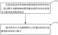
when the set-top box needs the POE module to provide compensation power supply, the voltage reduction circuit converts the power supply voltage output by the POE module into voltage adaptive to the set-top box, and the power supply switch circuit loads the voltage output by the voltage reduction element onto a mainboard of the set-top box.
Preferably, the step-down circuit converts the power supply voltage output by the POE module into a voltage adapted to the set top box, specifically:
and sending the first control signal to the voltage reduction element through a mainboard chip of the set top box so that the voltage reduction element converts the power supply voltage output by the POE module into a voltage adaptive to the set top box.
Preferably, the step-down element is configured to apply the voltage output by the power supply switch circuit to a motherboard of the set-top box, specifically:
and sending the third control signal to the triode through a mainboard chip of the set top box, wherein the third control signal is used for indicating the triode to conduct the triode per se and conducting the MOS tube when the triode is conducted so as to load the voltage output by the voltage reduction element on a mainboard of the set top box.
Preferably, the method further comprises the following steps:
when the voltage on the mainboard of the set top box is detected to be larger than a preset voltage threshold value, the second control signal is sent to the voltage reduction element through the mainboard chip of the set top box, and a fourth control signal is sent to the triode through the mainboard chip of the set top box;
the second control signal is used for indicating the voltage reduction element to block the power supply voltage output by the POE module;
the fourth control signal is used for indicating the triode to cut off the triode and cutting off the MOS tube when the triode is cut off so as to block the voltage output by the voltage reduction element.
The application provides a STB contains POE module, step-down circuit and power switch circuit, and the step-down circuit links to each other with POE module and power switch circuit respectively, and power switch circuit links to each other with the mainboard of STB, wherein: the voltage reduction circuit is used for converting the power supply voltage output by the POE module into voltage adaptive to the set top box when the set top box needs the POE module to provide compensation power supply; the power supply switch circuit is used for conducting when the set top box needs the POE module to provide compensation power supply, and loading the voltage output by the voltage reduction element onto a mainboard of the set top box when the set top box is conducted. The set top box that this application provided, its POE module can compensate the power supply to the set top box to reduce the power supply load of set top box, make the set top box can use the adapter of less power, reduce the manufacturing cost of product.
Drawings
Fig. 1 is a schematic structural diagram of a set top box according to an embodiment of the present application;
fig. 2 is a schematic flowchart of a set top box power supply adjustment method proposed in the present application;
fig. 3 is a POE voltage conversion circuit diagram according to an embodiment of the present invention;
fig. 4 is a power supply enabling circuit diagram of an IPTV product according to an embodiment of the present application;
FIG. 5 is a flow chart of the detection of the under-voltage circuit according to the embodiment of the present application;
FIG. 6 is a flow chart illustrating the detection of an over-voltage circuit according to an embodiment of the present invention;
fig. 7 is a power consumption diagram of a functional module of an IPTV product according to an embodiment of the present application;
fig. 8 is a power consumption diagram of different video sources and video formats of an IPTV product according to an embodiment of the present application.
Detailed Description
As described in the background art, in the prior art, the POE module can only supply power to itself, but cannot provide compensation power to other parts in the set-top box, which causes waste of power supply resources of the POE module. In theory, it is entirely possible to let the POE module provide the back-off power to the set-top box. However, the power supply voltage of the POE module is not adapted to the operating voltage of the set-top box, so that it has been difficult to implement the compensation power supply of the POE module to the set-top box.
Consequently, compensate the power supply in order to realize POE module to the STB, and then reduce the power supply load of STB, this application provides a STB, contains POE module, step-down circuit and power switch circuit, and step-down circuit links to each other with POE module and power switch circuit respectively, and power switch circuit links to each other with the mainboard of STB, wherein: the voltage reduction circuit is used for converting the power supply voltage output by the POE module into voltage adaptive to the set top box when the set top box needs the POE module to provide compensation power supply; the power supply switch circuit is used for conducting when the set top box needs the POE module to provide compensation power supply, and loading the voltage output by the voltage reduction element onto a mainboard of the set top box when the set top box is conducted. The set top box that this application provided, its POE module can compensate the power supply to the set top box to reduce the power supply load of set top box, make the set top box can use the adapter of less power, reduce the manufacturing cost of product.
Example one
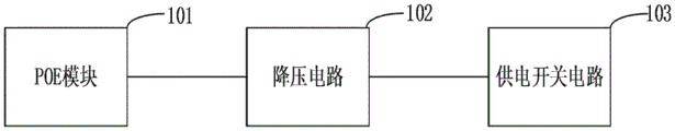
Fig. 1 is a schematic structural diagram of a set top box according to the present application, which mainly includes a POE module 101, a voltage dropping circuit 102, and a power supply switch circuit 103, and the following details of important components are as follows:
(1) POE module
The POE module plays the effect of compensation power supply in this application for the power supply is supplied with compensation for the STB according to the actual power consumption condition of STB. Because the voltage that POE module provided does not match with the operating voltage of STB, consequently still need carry out the vary voltage processing to the voltage of POE module.
(2) Voltage reduction circuit
In the embodiment of this application, step-down circuit plays the effect that converts the supply voltage of POE module into the voltage with the STB adaptation in this application. The voltage reduction circuit is connected with the POE module and the power supply switch circuit respectively and used for converting power supply voltage output by the POE module into voltage adaptive to the set top box when the set top box needs the POE module to provide compensation power supply.
In a preferred embodiment of the present application, the voltage-reducing circuit includes a voltage-reducing element including a voltage input interface, a ground interface, a first signal interface, a second signal interface, and a control interface. And the POE module comprises a voltage output interface, a grounding interface, a first signal interface and a second signal interface. The connection relationship of the interfaces is as follows:
the voltage input interface of step-down component links to each other with the voltage output interface of POE module, and the ground connection interface of step-down component links to each other with the ground connection interface of POE module, and the first signal interface of step-down component links to each other with the first signal interface of POE module, and the second signal interface of step-down component links to each other with the second signal interface of POE module, and the control interface of step-down component links to each other with the mainboard chip of STB. Through the connection relation, the interaction of the voltage reduction element and the POE module is realized, and then the voltage matched with the set top box is converted from the power supply voltage of the POE module.
In a preferred embodiment of the present application, the voltage-reducing circuit further includes a TVS tube connected to the voltage output interface of the voltage-reducing element and grounded.
The TVS tube is used for protecting the voltage reduction circuit when the voltage fluctuation of the circuit is large so as to prevent the voltage reduction circuit from being damaged.
(3) Power supply switch circuit
In the embodiment of the application, the power supply switch circuit is connected with the mainboard of the set top box and used for being switched on when the set top box needs the POE module to provide compensation power supply, and loading the voltage output by the voltage reduction element onto the mainboard of the set top box when the set top box is switched on.
In the preferred embodiment of the present application, the power supply switch circuit includes a transistor and a MOS transistor. And the voltage reduction element further comprises a voltage output interface. The connection mode of the interfaces is as follows:
the base electrode of the triode is connected with a mainboard chip of the set top box, the collector electrode of the triode is connected with the grid electrode of the MOS tube, and the emitting electrode of the triode is grounded;
the drain electrode of the MOS tube is connected with the voltage output interface of the voltage reduction element, and the source electrode of the MOS tube is connected with the mainboard of the set-top box.
The MOS transistor is a metal-oxide-semiconductor (semiconductor) field effect transistor, and is a voltage control element. When the voltage of the grid electrode is far larger than that of the source electrode, the MOS tube is conducted; when the voltage of the grid electrode is equal to or less than the voltage of the source electrode, the MOS tube is cut off. Also, the current is conducted from the source to the drain due to the internal parasitic diode.
Based on the above connection relationship, in the preferred embodiment of the present application, the voltage dropping element is configured to convert the power supply voltage output by the POE module into a voltage adapted to the set top box when receiving the first control signal sent by the main board chip of the set top box, and block the power supply voltage output by the POE module when receiving the second control signal sent by the main board chip of the set top box.
The triode is used for conducting when receiving a third control signal sent by a mainboard chip of the set-top box and conducting the MOS tube when conducting so as to load the voltage output by the voltage reduction element on the mainboard of the set-top box; and the MOS tube is cut off when a fourth control signal sent by a mainboard chip of the set-top box is received, and the MOS tube is cut off when the fourth control signal is cut off so as to block the voltage output by the voltage reduction element.
In a preferred embodiment of the present application, the power supply switching circuit further includes an energy storage element, the energy storage element is connected to the source of the MOS transistor and is grounded, and the energy storage element is used to protect the power supply switching circuit when the voltage fluctuation of the circuit is large, so as to prevent the power supply switching circuit from being damaged.
As can be seen from the above description, the set top box proposed in the present application has the following advantages compared with the prior art, including:
the application provides a STB contains POE module, step-down circuit and power switch circuit, and the step-down circuit links to each other with POE module and power switch circuit respectively, and power switch circuit links to each other with the mainboard of STB, wherein: the voltage reduction circuit is used for converting the power supply voltage output by the POE module into voltage adaptive to the set top box when the set top box needs the POE module to provide compensation power supply; the power supply switch circuit is used for conducting when the set top box needs the POE module to provide compensation power supply, and loading the voltage output by the voltage reduction element onto a mainboard of the set top box when the set top box is conducted. The set top box that this application provided, its POE module can compensate the power supply to the set top box to reduce the power supply load of set top box, make the set top box can use the adapter of less power, reduce the manufacturing cost of product.
Example two
The application provides a set top box power supply adjusting method, which is applied to the set top box provided by the first embodiment, when the set top box needs the POE module to provide compensation power supply, the power supply voltage output by the POE module is converted into voltage adaptive to the set top box through a voltage reduction circuit, and the voltage output by a voltage reduction element is loaded onto a mainboard of the set top box through a power supply switch circuit.
As shown in fig. 2, a schematic flow chart of a set top box power supply adjustment method proposed by the present application can be seen from the following drawings:
s201, when the set top box needs the POE module to provide compensation power supply, the voltage reduction circuit converts the power supply voltage output by the POE module into voltage adaptive to the set top box.
And S202, loading the voltage output by the voltage reduction element on a mainboard of the set top box through the power supply switch circuit.
In a specific application scenario, the step-down circuit converts the power supply voltage output by the POE module into a voltage adapted to the set top box, specifically:
and sending the first control signal to the voltage reduction element through a mainboard chip of the set top box so that the voltage reduction element converts the power supply voltage output by the POE module into a voltage adaptive to the set top box.
In a specific application scenario, the step-down element applies the voltage output by the voltage-reducing element to a motherboard of the set-top box through the power supply switch circuit, specifically:
and sending the third control signal to the triode through a mainboard chip of the set top box, wherein the third control signal is used for indicating the triode to conduct the triode per se and conducting the MOS tube when the triode is conducted so as to load the voltage output by the voltage reduction element on a mainboard of the set top box.
In a specific application scenario, the method further includes:
when the voltage on the mainboard of the set top box is detected to be larger than a preset voltage threshold value, the second control signal is sent to the voltage reduction element through the mainboard chip of the set top box, and a fourth control signal is sent to the triode through the mainboard chip of the set top box;
the second control signal is used for indicating the voltage reduction element to block the power supply voltage output by the POE module;
the fourth control signal is used for indicating the triode to cut off the triode and cutting off the MOS tube when the triode is cut off so as to block the voltage output by the voltage reduction element.
As can be seen from the above description, the set top box proposed in the present application has the following advantages compared with the prior art, including:
the application provides a STB contains POE module, step-down circuit and power switch circuit, and the step-down circuit links to each other with POE module and power switch circuit respectively, and power switch circuit links to each other with the mainboard of STB, wherein: the voltage reduction circuit is used for converting the power supply voltage output by the POE module into voltage adaptive to the set top box when the set top box needs the POE module to provide compensation power supply; the power supply switch circuit is used for conducting when the set top box needs the POE module to provide compensation power supply, and loading the voltage output by the voltage reduction element onto a mainboard of the set top box when the set top box is conducted. The set top box that this application provided, its POE module can compensate the power supply to the set top box to reduce the power supply load of set top box, make the set top box can use the adapter of less power, reduce the manufacturing cost of product.
In order to further illustrate the technical idea of the present invention, the technical solution of the present invention will now be described with reference to specific application scenarios.
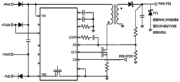
The POE can provide a direct current power supply of about 45V, and the power consumption can be more than ten watts, but the voltage far exceeds the maximum value of the power supply voltage of most consumer electronics such as an IPTV box, so that it is necessary to perform voltage reduction conversion and isolation design at the IPTV end to achieve a safe and reliable power supply voltage PWR _ POE (e.g., 12V for general use) that can also satisfy the power supply voltage of the terminal device.
Fig. 3 is a diagram of a POE voltage conversion circuit according to the embodiment of the present application, where the circuit structure is used to convert a high voltage of a POE module into a low voltage suitable for a set-top box. In fig. 2, the POE-DCDC pin is a control pin of the switching circuit, and when the CPU outputs a high level signal to the pin, the switching circuit is started, so that the POE module outputs an adaptive 12V voltage, and when the CPU outputs a low level signal to the pin, the switching circuit is closed, so that the POE module stops outputting the voltage.
In addition, still be equipped with the TVS pipe at converting circuit's power output side (PWR _ POE) and carry out overvoltage protection to when the power supply is unusual, can play the guard action to the POE module.
Fig. 4 is a power supply enabling circuit diagram of an IPTV product according to the embodiment of the present application, where the circuit diagram is between a power supply output interface of a POE module and a power supply input interface of a set-top box, and is used to control whether adaptive voltage output by the POE module is loaded on the set-top box. A POE _ EN pin in the figure is an enabling control pin, when the CPU outputs a high level signal to the POE _ EN pin, a power supply enabling circuit is conducted, and adaptive voltage output by the POE is loaded on the set top box; when the CPU outputs a low level signal to the POE _ EN pin, the power supply enabling circuit is cut off, and the adaptive voltage output by the POE cannot be loaded on the set top box.
In addition, in order to ensure the fluctuation caused in the power supply switching process in a very short time (within ms level), an energy storage element and an electrolytic capacitor of 220uF are required to be added at the power supply input end of the STB/OTT box so as to reduce the unnecessary voltage fluctuation influence on the system caused by the change caused at the switching moment. Meanwhile, strong current and weak current isolation protection measures are required.
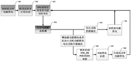
As shown in fig. 5, a flow chart of detecting the brown-out circuit according to an embodiment of the present invention is shown, and it can be seen that the flow chart of detecting the brown-out circuit includes the following steps:
s501, when initialization is completed, only a low-power supply is used for supplying power;
s502, finishing normal starting of the set top box;
s503, the CPU monitors the power consumption change of the function in real time;
s504, detecting the transient state of the undervoltage circuit;
s505, if the voltage power consumption can meet the requirement, the power supply of the original power supply is kept;
s506, if the voltage power consumption can not meet the requirement, enabling POE _ EN and POE _ DCDC;
s507, the POE module performs compensation power supply;
and S508, synthesizing a high-power supply for power supply.
Fig. 6 shows a flow chart of detecting an overvoltage circuit according to an embodiment of the present application, and it can be seen that the flow chart of detecting an overvoltage circuit includes the following steps:
s601, when the initialization is completed, only a low-power supply is used for supplying power;
s602, finishing normal starting of the set top box;
s603, the CPU monitors the power consumption change of the function in real time;
s604, detecting the transient state of the overvoltage circuit;
s605, if the voltage is abnormal, sequentially closing the POE _ EN and the POE _ DCDC enable;
and S606, if the voltage is abnormal, keeping the POE _ EN and POE _ DCDC enabled unchanged.
As shown in fig. 7, a power consumption diagram of a functional module of an IPTV product according to an embodiment of the present application is shown, and as can be seen from the diagram, in a set-top box, power consumption of CPU & DDR & FASH is Pa, power consumption of USB 2.0 is Pb, power consumption of USB3.0 is Pc, power consumption of BLE is Pd, power consumption of WiFi 802.11n is Pe, power consumption of WiFi 802.11AC is Pf, power consumption of WiFi 802.11n & WiFi 802.11n is Pg, power consumption of Ethernet is Ph, power consumption of Tuner & Demod is Pi, power consumption of Full bad Tuner is Pj, and power consumption Pk of a 4G module. In the application, the power of each function of the set top box is quantized, so that the power consumed by the set top box at present is judged according to the started function of the set top box, and when the power consumed by the set top box at present is greater than a preset power threshold value, the power supply of the POE module is started.
As shown in fig. 8, which is a power consumption diagram of different video sources and video formats of an IPTV product according to an embodiment of the present invention, it can be known from the diagram that, in a set-top box, when a playback source is a usb disk, the power consumption for playing a standard definition video source is P1, the power consumption for playing a high definition video source is P2, and the power consumption for playing a 4K video source is P3; when the playing source is a mobile hard disk, the power consumption of playing the standard definition film source is P4, the power consumption of playing the high definition film source is P5, and the power consumption of playing the 4K film source is P6; when the playing source is Ethernet & Service, the power consumption for playing the standard definition source is P7, the power consumption for playing the high definition source is P8, and the power consumption for playing the 4K source is P9. In the application, the power consumed by the set top box is determined according to the current playing condition of the set top box just by quantizing the playing power consumption of each playing film source of the set top box, and when the current power consumed by the set top box is greater than a preset power threshold, the power supply of the POE module is started.
As can be seen from the above description, the set top box proposed in the present application has the following advantages compared with the prior art, including:
the application provides a STB contains POE module, step-down circuit and power switch circuit, and the step-down circuit links to each other with POE module and power switch circuit respectively, and power switch circuit links to each other with the mainboard of STB, wherein: the voltage reduction circuit is used for converting the power supply voltage output by the POE module into voltage adaptive to the set top box when the set top box needs the POE module to provide compensation power supply; the power supply switch circuit is used for conducting when the set top box needs the POE module to provide compensation power supply, and loading the voltage output by the voltage reduction element onto a mainboard of the set top box when the set top box is conducted. The set top box that this application provided, its POE module can compensate the power supply to the set top box to reduce the power supply load of set top box, make the set top box can use the adapter of less power, reduce the manufacturing cost of product.
Finally, the description is as follows: the above embodiments are only used to illustrate the technical solution of the present invention, and not to limit the same; while the invention has been described in detail and with reference to the foregoing embodiments, those skilled in the art will appreciate that; the technical solutions described in the foregoing embodiments may still be modified, or some or all of the technical features may be equivalently replaced; such modifications and substitutions do not depart from the spirit of the corresponding technical solutions and scope of the present invention as defined in the appended claims.
Through the above description of the embodiments, those skilled in the art will clearly understand that the present invention may be implemented by hardware, or by software plus a necessary general hardware platform. Based on such understanding, the technical solution of the present invention can be embodied in the form of a software product, which can be stored in a non-volatile storage medium (which can be a CD-ROM, a usb disk, a removable hard disk, etc.), and includes several instructions for enabling a computer device (which can be a personal computer, a server, or a network device, etc.) to execute the method according to the implementation scenarios of the present invention.
Those skilled in the art will appreciate that the figures are merely schematic representations of one preferred implementation scenario and that the blocks or flow diagrams in the figures are not necessarily required to practice the present invention.
Those skilled in the art will appreciate that the modules in the devices in the implementation scenario may be distributed in the devices in the implementation scenario according to the description of the implementation scenario, or may be located in one or more devices different from the present implementation scenario with corresponding changes. The modules of the implementation scenario may be combined into one module, or may be further split into a plurality of sub-modules.
The above-mentioned invention numbers are merely for description and do not represent the merits of the implementation scenarios.
The above disclosure is only a few specific implementation scenarios of the present invention, however, the present invention is not limited thereto, and any variations that can be made by those skilled in the art are intended to fall within the scope of the present invention.
Claims (8)
1. The utility model provides a set top box, its characterized in that contains POE module, step-down circuit and power supply switch circuit, step-down circuit respectively with POE module and power supply switch circuit links to each other, power supply switch circuit with the mainboard of set top box links to each other, wherein:
the voltage reduction circuit is used for converting the power supply voltage output by the POE module into voltage adaptive to the set top box when the set top box needs the POE module to provide compensation power supply;
the power supply switch circuit is used for conducting when the set top box needs the POE module to provide compensation power supply, and loading the voltage output by the voltage reduction element onto a mainboard of the set top box when the set top box is conducted;
the power supply switch circuit comprises a triode and an MOS (metal oxide semiconductor) tube, wherein the triode is used for conducting when receiving a third control signal and conducting the MOS tube when conducting; and cutting off when receiving the fourth control signal, and cutting off the MOS tube when cutting off the MOS tube.
2. The set top box of claim 1, wherein the voltage-reduction circuit comprises a voltage-reduction element comprising a voltage input interface, a ground interface, a first signal interface, a second signal interface, and a control interface, the POE module comprises a voltage output interface, a ground interface, a first signal interface, and a second signal interface, wherein:
the voltage input interface of step-down component with the voltage output interface of POE module links to each other, the ground connection interface of step-down component with the ground connection interface of POE module links to each other, the first signal interface of step-down component with the first signal interface of POE module links to each other, the second signal interface of step-down component with the second signal interface of POE module links to each other, the control interface of step-down component with the mainboard chip of STB links to each other.
3. The set top box of claim 2, wherein the voltage-dropping element further comprises a voltage output interface, wherein:
the base electrode of the triode is connected with the mainboard chip of the set top box, the collector electrode of the triode is connected with the grid electrode of the MOS tube, and the emitting electrode of the triode is grounded;
the drain electrode of the MOS tube is connected with the voltage output interface of the voltage reduction element, and the source electrode of the MOS tube is connected with the mainboard of the set-top box.
4. The set top box of claim 3, wherein:
the voltage reduction element is used for converting the power supply voltage output by the POE module into the voltage adaptive to the set top box when receiving a first control signal sent by a main board chip of the set top box, and blocking the power supply voltage output by the POE module when receiving a second control signal sent by the main board chip of the set top box.
5. The set top box of claim 3, wherein the voltage-reduction circuit further comprises a TVS transistor, and the power switching circuit further comprises an energy storage element, wherein:
the TVS tube is connected with a voltage output interface of the voltage reduction element and is grounded;
the energy storage element is connected with the source electrode of the MOS tube and is grounded.
6. Set-top box power supply adjustment method, applied in a set-top box according to any of claims 1 to 5, the method comprising at least:
when the set top box needs the POE module to provide compensation power supply, the voltage reduction circuit converts the power supply voltage output by the POE module into voltage matched with the set top box, and the power supply switch circuit loads the voltage output by the voltage reduction element onto a main board of the set top box;
the fourth control signal is used for indicating the triode to cut off the triode and cutting off the MOS tube when the triode is cut off so as to block the voltage output by the voltage reduction element;
the step-down element is configured to apply the voltage output by the step-down element to a motherboard of the set-top box through the power supply switch circuit, specifically:
and sending the third control signal to the triode through a mainboard chip of the set top box, wherein the third control signal is used for indicating the triode to conduct the triode per se and conducting the MOS tube when the triode is conducted so as to load the voltage output by the voltage reduction element on a mainboard of the set top box.
7. The method according to claim 6, wherein the step-down circuit converts the power supply voltage output by the POE module into a voltage adapted to the set top box, specifically:
and sending a first control signal to the voltage reduction element through a mainboard chip of the set top box so that the voltage reduction element converts the power supply voltage output by the POE module into a voltage adaptive to the set top box.
8. The method of claim 7, further comprising:
when the voltage on the mainboard of the set top box is detected to be larger than a preset voltage threshold value, a second control signal is sent to the voltage reduction element through the mainboard chip of the set top box;
the second control signal is used for indicating the voltage reduction element to block the power supply voltage output by the POE module.
Priority Applications (1)
| Application Number | Priority Date | Filing Date | Title |
|---|---|---|---|
| CN201611005570.5A CN106792184B (en) | 2016-11-16 | 2016-11-16 | Set top box and set top box power supply adjusting method |
Applications Claiming Priority (1)
| Application Number | Priority Date | Filing Date | Title |
|---|---|---|---|
| CN201611005570.5A CN106792184B (en) | 2016-11-16 | 2016-11-16 | Set top box and set top box power supply adjusting method |
Publications (2)
| Publication Number | Publication Date |
|---|---|
| CN106792184A CN106792184A (en) | 2017-05-31 |
| CN106792184B true CN106792184B (en) | 2021-11-09 |
Family
ID=58968479
Family Applications (1)
| Application Number | Title | Priority Date | Filing Date |
|---|---|---|---|
| CN201611005570.5A Active CN106792184B (en) | 2016-11-16 | 2016-11-16 | Set top box and set top box power supply adjusting method |
Country Status (1)
| Country | Link |
|---|---|
| CN (1) | CN106792184B (en) |
Families Citing this family (1)
| Publication number | Priority date | Publication date | Assignee | Title |
|---|---|---|---|---|
| CN107425506B (en) * | 2017-09-07 | 2020-12-11 | 浙江亿众机器人有限公司 | Multi-path power supply protection circuit |
Citations (2)
| Publication number | Priority date | Publication date | Assignee | Title |
|---|---|---|---|---|
| CN204836199U (en) * | 2015-07-29 | 2015-12-02 | 杭州海康威视数字技术股份有限公司 | POE power module and be provided with POE power module's cable |
| CN105515559A (en) * | 2016-01-26 | 2016-04-20 | 深圳市共进电子股份有限公司 | Voltage switching circuit applied to PSE switch |
Family Cites Families (6)
| Publication number | Priority date | Publication date | Assignee | Title |
|---|---|---|---|---|
| US9596031B2 (en) * | 2005-03-01 | 2017-03-14 | Alexander Ivan Soto | System and method for a subscriber-powered network element |
| KR101220171B1 (en) * | 2011-03-31 | 2013-01-21 | 가온미디어 주식회사 | Home built-in Ethernet-based multi-room system, and base set-top boxe devices for the same |
| US9485103B2 (en) * | 2012-12-12 | 2016-11-01 | Hewlett-Packard Development Company, L.P. | Bridge circuit for Ethernet powered device |
| CN103763630A (en) * | 2014-01-23 | 2014-04-30 | 深圳市同洲电子股份有限公司 | Gateway equipment and protocol conversion method |
| CN103779972B (en) * | 2014-02-11 | 2016-05-11 | 厦门亿联网络技术股份有限公司 | A kind of simple and easy reliable POE device |
| CN105072363B (en) * | 2015-09-25 | 2018-02-13 | 四川金网通电子科技有限公司 | Wireless set-top box with POE ports |
-
2016
- 2016-11-16 CN CN201611005570.5A patent/CN106792184B/en active Active
Patent Citations (2)
| Publication number | Priority date | Publication date | Assignee | Title |
|---|---|---|---|---|
| CN204836199U (en) * | 2015-07-29 | 2015-12-02 | 杭州海康威视数字技术股份有限公司 | POE power module and be provided with POE power module's cable |
| CN105515559A (en) * | 2016-01-26 | 2016-04-20 | 深圳市共进电子股份有限公司 | Voltage switching circuit applied to PSE switch |
Non-Patent Citations (2)
| Title |
|---|
| 以太网供电中受电设备的芯片设计与研究;宁志华;《中国优秀博士学位论文全文数据库 信息科技辑》;20140715;全文 * |
| 以太网供电系统中受电设备接口芯片设计;祁龙飞;《中国优秀硕士学位论文全文数据库 信息科技辑》;20150715;全文 * |
Also Published As
| Publication number | Publication date |
|---|---|
| CN106792184A (en) | 2017-05-31 |
Similar Documents
| Publication | Publication Date | Title |
|---|---|---|
| US10333412B2 (en) | Power delivery device, AC adapter, AC charger, electronic apparatus and power delivery system | |
| US9252842B2 (en) | Power over coaxial cable | |
| US10536080B2 (en) | Power delivery device, AC adapter, AC charger, electronic apparatus and power delivery system, each capable of controlling output voltage value and available output current value | |
| US20120293136A1 (en) | Dual-interface card reader module | |
| US20140337880A1 (en) | Peer-to-Peer Communication Advertising Method | |
| US20110016494A1 (en) | Method and Apparatus to Facilitate Viewing Television on a Mobile Device | |
| US10333409B2 (en) | Power delivery device, AC adapter, AC charger, electronic apparatus and power delivery system | |
| US20170040819A1 (en) | Power delivery device, ac adapter, ac charger, electronic apparatus and power delivery system | |
| US11240559B2 (en) | Content reproducing apparatus and content reproducing method | |
| CN103455118A (en) | Detection of fast supply ramp in reset circuit | |
| US20040232768A1 (en) | Portable electronic device for receiving power over a network | |
| CN106792184B (en) | Set top box and set top box power supply adjusting method | |
| KR102609536B1 (en) | Electronic apparatus | |
| CN102714507A (en) | Systems and methods for interfacing a white space device with a host device | |
| US20130134801A1 (en) | Power supply circuit for antenna, antenna control system, and digital communication device | |
| US20120112722A1 (en) | Power supply circuit | |
| CN205356614U (en) | Multimedia terminal with 4G focus and live TV program propelling movement function | |
| US20200186855A1 (en) | Smart remote monitoring system and method | |
| KR20080097775A (en) | Method and system for receiving digital broadcasting by using mobile communication terminal | |
| US7589793B2 (en) | Television receiver that can receive both regular broadcast-satellite television and digital terrestrial broadcast | |
| US20190313339A1 (en) | Wifi power supply switching method, circuit and apparatus, and storage medium | |
| CN103686258A (en) | Set top box and method for detecting interference signals of set top box | |
| US11057675B2 (en) | Media streaming device and protection method of the same | |
| CN102572350A (en) | Mobile TV off-line recording device and off-line recording method thereof | |
| US20230216904A1 (en) | Media streaming device and media streaming method |
Legal Events
| Date | Code | Title | Description |
|---|---|---|---|
| PB01 | Publication | ||
| PB01 | Publication | ||
| SE01 | Entry into force of request for substantive examination | ||
| SE01 | Entry into force of request for substantive examination | ||
| GR01 | Patent grant | ||
| GR01 | Patent grant |