CN106762698B - Quick maintenance centrifugal pump - Google Patents
Quick maintenance centrifugal pump Download PDFInfo
- Publication number
- CN106762698B CN106762698B CN201611268011.3A CN201611268011A CN106762698B CN 106762698 B CN106762698 B CN 106762698B CN 201611268011 A CN201611268011 A CN 201611268011A CN 106762698 B CN106762698 B CN 106762698B
- Authority
- CN
- China
- Prior art keywords
- motor
- impeller
- base
- bolt
- lifting cylinder
- Prior art date
- Legal status (The legal status is an assumption and is not a legal conclusion. Google has not performed a legal analysis and makes no representation as to the accuracy of the status listed.)
- Active
Links
Images


Classifications
-
- F—MECHANICAL ENGINEERING; LIGHTING; HEATING; WEAPONS; BLASTING
- F04—POSITIVE - DISPLACEMENT MACHINES FOR LIQUIDS; PUMPS FOR LIQUIDS OR ELASTIC FLUIDS
- F04D—NON-POSITIVE-DISPLACEMENT PUMPS
- F04D13/00—Pumping installations or systems
- F04D13/02—Units comprising pumps and their driving means
- F04D13/06—Units comprising pumps and their driving means the pump being electrically driven
-
- F—MECHANICAL ENGINEERING; LIGHTING; HEATING; WEAPONS; BLASTING
- F04—POSITIVE - DISPLACEMENT MACHINES FOR LIQUIDS; PUMPS FOR LIQUIDS OR ELASTIC FLUIDS
- F04D—NON-POSITIVE-DISPLACEMENT PUMPS
- F04D29/00—Details, component parts, or accessories
- F04D29/60—Mounting; Assembling; Disassembling
- F04D29/62—Mounting; Assembling; Disassembling of radial or helico-centrifugal pumps
- F04D29/628—Mounting; Assembling; Disassembling of radial or helico-centrifugal pumps especially adapted for liquid pumps
-
- H—ELECTRICITY
- H02—GENERATION; CONVERSION OR DISTRIBUTION OF ELECTRIC POWER
- H02K—DYNAMO-ELECTRIC MACHINES
- H02K5/00—Casings; Enclosures; Supports
- H02K5/26—Means for adjusting casings relative to their supports
Abstract
The invention discloses a centrifugal pump capable of being maintained rapidly, which mainly comprises a pump body, an impeller, a pump cover, an impeller nut, a front sealing ring, an impeller transmission key, a rear sealing ring, a locking nut, a mechanical seal, a disassembling screw, a motor and a base.
Description
Technical Field
The invention relates to the technical field of mechanical engineering pumps, in particular to a centrifugal pump which is convenient and quick to maintain.
Background
At present, the horizontal direct-connection centrifugal pump is widely used for conveying clear water without solid particles or liquid with physical and chemical properties similar to water, and is mainly used for occasions such as urban heating, circulating water of an air conditioning system, urban tap water, industrial circulating water and the like. When the water pump with the motor with the power of more than 5.5 kilowatts is maintained, the maintenance is needed by means of hoisting equipment due to the heavy weight of the motor and manual moving; because the impeller nut external diameter is big, the socket spanner that needs is big, carries to user's scene inconvenient, and pump maintenance time is long, and is with high costs.
And (3) searching: CN2014204779388 discloses a centrifugal pump, CN2014200138144 discloses a movable centrifugal pump, CN2016202152342 discloses a centrifugal pump body which is easy to move, and these three structures all solve the substantial technical problem of inconvenient pump body transportation, but when the water pump needs to be maintained, because the motor weight is large, the manual movement is not carried out, and the maintenance is also needed by means of lifting equipment.
Disclosure of Invention
The invention aims to solve the defects of the prior art, and provides the centrifugal pump which is novel in structure, stable in performance, simple and quick to operate, small in pump running vibration, free of a lifting tool, time-saving and labor-saving.
The technical scheme adopted for solving the technical problems is as follows:
the utility model provides a centrifugal pump of quick maintenance, mainly includes the pump body, impeller, pump cover, impeller nut, preceding sealing ring, impeller drive key, back sealing ring, lock nut, mechanical seal, dismantlement screw, motor and base, its characterized in that is equipped with universal pulley, horizontal spacing and vertical spacing, the lower extreme of the lower margin installation panel that the motor lower extreme was equipped with is equipped with the pulley landing leg respectively, pulley landing leg lower extreme is equipped with universal pulley, the motor passes through universal pulley and base up end roll connection, base up end both sides are equipped with vertical spacing respectively, and the rear end is equipped with horizontal spacing, the motor both sides are respectively through pulley landing leg and vertical spacing sliding connection to do benefit to the direction to motor longitudinal movement, when to maintain to the pump, the motor drags backward, and the motor is under the direction of the roll of universal pulley and pulley landing leg, moves to the base rear portion until the universal pulley of rear portion leans on to horizontal spacing, has solved the substantial technical problem of pump maintenance time, needs to have reached maintenance convenient, swift, time saving effect with the help of lifting tool.
The invention can be provided with a rotating device at the center of the bottom of the motor, the rotating device comprises a rotating bearing seat, a rotating bearing, a lifting cylinder, a control switch and a support, the rotating bearing seat is fixed at the lower end of the motor, the upper end of the lifting cylinder is fixedly connected with an inner ring of the rotating bearing arranged in the rotating bearing seat through a telescopic rod, the lower end of the lifting cylinder is fixedly connected with the support, the lifting cylinder is controlled by the control switch, when the motor needs to be maintained in a larger space, the control switch is started, the lifting cylinder drives the motor to ascend, the universal roller leaves the base, the motor can be rotated manually, and the motor can be rotated for a certain angle under the action of the rotating bearing, so that the motor can be maintained, and the maintenance space is greatly widened.
The invention can also be provided with a positioning groove on the upper end surface of the base, when the motor is moved to the rear part of the base and needs to be maintained in a larger rotation space, the lifting cylinder stretches to enable the support to be positioned in the positioning groove, so that the motor is positioned, after the motor is well maintained, the motor is rotated, the two sides of the motor are corresponding to the longitudinal limiting strips, the lifting cylinder is started again, the lifting cylinder drives the motor to descend, the pulley legs on the two sides of the motor are fast corresponding to the longitudinal limiting strips, after the universal pulley is contacted with the base, and after the support at the lower end of the lifting cylinder leaves the positioning groove, the control switch is closed, and a maintainer can fast push the motor to the installation position, so that the maintenance speed is obviously improved, manpower and material resources are saved, and the maintenance speed is improved.
According to the invention, the pulley screw rods can be respectively connected with the four threaded holes of the motor anchor mounting panel in a threaded manner, the lower ends of the pulley screw rods of the motor anchor mounting panel are connected with the universal pulleys, and the pulley screw rods are fixedly connected with the motor anchor mounting panel through the locking nuts, so that the height of each foot of the motor can be adjusted according to the pulley screw rods and the locking nuts, the levelness of the motor shaft and the motor shaft can be adjusted, and the effect of convenience in mounting can be achieved.
The impeller nut is composed of the bolt and the top plate, the top plate is sleeved on the stud of the bolt and is fixedly connected with the screw crown, the impeller is fixed on the motor shaft by the bolt through the top plate, and when maintenance is needed, the impeller nut can be detached by using a small-sized socket spanner, so that the substantial technical problems that the external diameter of the impeller nut is large, the socket spanner needs to be carried, and the impeller nut is inconvenient to carry to a user on site are solved, and the effect of quick maintenance is achieved.
The invention has the advantages of novel structure, stable performance, simple and quick operation, small vibration of pump operation, no need of hoisting tool, time and labor saving and the like due to the adoption of the structure.
Drawings
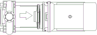
Fig. 1 is a schematic structural view of the present invention.
Fig. 2 is a schematic view of the construction of the impeller nut of the present invention.
Fig. 3 is a top view of the invention after rearward movement.
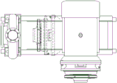
Fig. 4 is a schematic view of the present invention rotated 90 degrees after being moved backward.
Reference numerals: pump body 1, impeller 2, pump cover 3, impeller nut 4, front sealing ring 5, impeller drive key 6, back sealing ring 7, lock nut 8, mechanical seal 9, dismantlement screw 10, motor 11, universal pulley 12, lock nut 13, base 14, vertical fibre strip 15, horizontal spacing 16, lower margin installation panel 18, bolt 19, roof 20, lift cylinder 21, support 22.
Detailed Description
The invention is further described below with reference to the accompanying drawings:
as shown in the drawing, a centrifugal pump capable of being maintained rapidly mainly comprises a pump body 1, an impeller 2, a pump cover 3, an impeller nut 4, a front sealing ring 5, an impeller transmission key 6, a rear sealing ring 7, a lock nut 8, a mechanical seal 9, a dismounting screw 10, a motor 11 and a base 14, wherein the connection relation among the pump body 1, the impeller 2, the pump cover 3, the impeller nut 4, the front sealing ring 5, the impeller transmission key 6, the rear sealing ring 7, the lock nut 8, the mechanical seal 9, the dismounting screw 10 and the motor 11 is the same as that of the prior art, and is not repeated.
The invention can be provided with a rotating device at the center of the bottom of the motor, the rotating device comprises a rotating bearing seat, a rotating bearing, a lifting cylinder 21, a control switch and a support 22, the rotating bearing seat is fixed at the lower end of the motor, the upper end of the lifting cylinder is fixedly connected with an inner ring of the rotating bearing arranged in the rotating bearing seat through a telescopic rod, the lower end of the lifting cylinder is fixedly connected with the support, the lifting cylinder is controlled by the control switch, when the motor needs to be maintained in a larger space, the control switch is started, the lifting cylinder drives the motor to lift, the universal roller is enabled to leave the base, the motor can be rotated manually for a certain angle under the action of the rotating bearing, the motor can be maintained, and the maintenance space is greatly widened.
The invention can also be provided with a positioning groove on the upper end surface of the base, when the motor is moved to the rear part of the base and a large rotating space is needed for quick inspection or maintenance, the lifting cylinder stretches to enable the support to be positioned in the positioning groove, so that the motor is positioned, after the motor is repaired, the motor is rotated, the two sides of the motor correspond to the longitudinal limiting strips, the lifting cylinder is restarted, the lifting cylinder drives the motor to descend, the pulley legs on the two sides of the motor are enabled to be corresponding to the longitudinal limiting strips quickly, after the universal pulley is contacted with the base, and the support at the lower end of the lifting cylinder is enabled to leave the positioning groove, the control switch is turned off, and a maintainer can push the motor to the installation position quickly, so that the maintenance speed is improved obviously, manpower and material resources are saved, and the maintenance speed is improved.
According to the invention, the pulley screw rods 17 can be respectively connected with four threaded holes of the foot installation panel of the motor 11 in a threaded manner, the lower end of the pulley screw rods 17 of the foot installation panel of the motor 11 is connected with the universal pulley 12, and the pulley screw rods 17 are fixedly connected with the foot installation panel 18 of the motor 11 through the locking nuts 8, so that the height of each foot of the motor can be adjusted according to the pulley screw rods 17 and the locking nuts 8, the levelness of the installation of a motor shaft and the motor shaft can be adjusted, and the effect of convenience in installation can be achieved.
The impeller nut 4 is composed of the bolt 19 and the top plate 20, the top plate 20 is sleeved on a stud of the bolt 19 and is fixedly connected with a screw crown of the bolt 19, the bolt 19 fixes the impeller 2 on a motor shaft through the top plate 20, when maintenance is needed, the impeller nut 4 can be detached by using a socket spanner with a small model, the substantial technical problems that the outer diameter of the impeller nut 4 is large, the socket spanner needs to be carried in a large way, and the carrying is inconvenient to a user on site are solved, and the effect of quick maintenance is achieved.
When the invention is installed, the impeller is fixed on the motor shaft by the impeller nut, the pump body is connected with the pump cover by bolts, the pump cover is connected with the motor by bolts, 2 dismounting screws are arranged on the flange connected with the pump body, 4 universal pulleys are arranged on the motor anchor, the height of the universal pulleys is adjusted by the pulley screw rod and the motor anchor threaded hole, and the locking nut is used for locking after the height is adjusted in place.
During pump maintenance, loosen the bolt between the pump body and the pump cover, break away from the pump body with parts such as pump cover, impeller, motor through dismantling the screw, because of 4 universal pulleys of motor bottom installation, motor 11 is under the direction of the roll of universal pulley 12 and pulley landing leg, remove to base 14 rear portion, until rear portion universal pulley 12 lean on horizontal spacing 16 can, the maintenance speed has been improved greatly, reuse socket wrench of less specification demolish the impeller nut, demolish the impeller from the motor shaft, can change mechanical seal, two maintenance workers need not borrow lifting means, can accomplish and change mechanical seal in half an hour.
When the motor needs great rotational space maintenance, the lift cylinder stretches, make the support be located the constant head tank, reach the effect of location motor position, after the motor is repaiied, the rotating electrical machines, make the motor both sides correspond vertical spacing, restart the lift cylinder, the lift cylinder drives the motor and descends, make the pulley support leg of motor both sides quick and vertical spacing corresponding, after universal pulley and base contact, and make the support of lift cylinder lower extreme leave the constant head tank, close control switch, the maintenance personal can push away the motor to the installation position fast, make maintenance speed show improvement, also saved manpower and materials simultaneously, maintenance speed has been improved.
Due to the adoption of the structure, the invention has the advantages of novel structure, stable performance, simple and quick operation, small vibration of the pump operation, no need of a lifting tool, time saving, labor saving and the like.
Claims (2)
1. The utility model provides a centrifugal pump of quick maintenance, mainly includes the pump body, impeller, pump cover, impeller nut, preceding sealing ring, impeller drive key, back sealing ring, lock nut, mechanical seal, dismantlement screw, motor and base, its characterized in that still is equipped with universal pulley, horizontal spacing and vertical spacing, the lower extreme of the lower limb installation panel that the motor lower extreme was equipped with is equipped with universal pulley, the motor is through universal pulley and base up end roll connection, base up end both sides are equipped with vertical spacing respectively, and the rear end is equipped with horizontal spacing, motor both sides respectively with vertical spacing sliding connection, the motor bottom center is equipped with rotary device, rotary device includes swivel bearing frame, swivel bearing, lifting cylinder, control switch and support, the swivel bearing frame is fixed in the motor lower extreme, lifting cylinder upper end is equipped with swivel bearing inner race fixed connection through telescopic link and swivel bearing frame, lower extreme and support fixed connection, the lifting cylinder is controlled through control switch, the base up end is equipped with the constant head tank, works as the motor is moved to the base rear portion, when the motor needs rotation space, makes the support motor positioning groove lie in four lower limb installation panels have four lower limb installation screw rods and screw rods, screw rod fixed connection screw rod and screw rod.
2. The quick service centrifugal pump of claim 1 wherein said impeller nut is comprised of a bolt and a top plate, said top plate being received over a stud of the bolt and fixedly connected to a crown of the bolt, said bolt securing the impeller to the motor shaft via the top plate.
Priority Applications (1)
| Application Number | Priority Date | Filing Date | Title |
|---|---|---|---|
| CN201611268011.3A CN106762698B (en) | 2016-12-31 | 2016-12-31 | Quick maintenance centrifugal pump |
Applications Claiming Priority (1)
| Application Number | Priority Date | Filing Date | Title |
|---|---|---|---|
| CN201611268011.3A CN106762698B (en) | 2016-12-31 | 2016-12-31 | Quick maintenance centrifugal pump |
Publications (2)
| Publication Number | Publication Date |
|---|---|
| CN106762698A CN106762698A (en) | 2017-05-31 |
| CN106762698B true CN106762698B (en) | 2023-05-12 |
Family
ID=58951649
Family Applications (1)
| Application Number | Title | Priority Date | Filing Date |
|---|---|---|---|
| CN201611268011.3A Active CN106762698B (en) | 2016-12-31 | 2016-12-31 | Quick maintenance centrifugal pump |
Country Status (1)
| Country | Link |
|---|---|
| CN (1) | CN106762698B (en) |
Families Citing this family (2)
| Publication number | Priority date | Publication date | Assignee | Title |
|---|---|---|---|---|
| CN110953164A (en) * | 2018-09-26 | 2020-04-03 | 苏州轩扬泵业科技有限公司 | Novel rotatable liftable formula water pump |
| CN114922838A (en) * | 2022-06-24 | 2022-08-19 | 浙江鹏阳风机有限公司 | Papermaking of two air outlets is with energy-efficient fan |
Family Cites Families (10)
| Publication number | Priority date | Publication date | Assignee | Title |
|---|---|---|---|---|
| JPS5791649A (en) * | 1980-11-28 | 1982-06-07 | Toshiba Corp | Movable rotary stand |
| CN1075603C (en) * | 1999-09-07 | 2001-11-28 | 薛铭 | Directly linked pump detachable quickly |
| CN2597723Y (en) * | 2003-01-23 | 2004-01-07 | 方斌 | Adjustable water pump base |
| CN202737650U (en) * | 2012-09-18 | 2013-02-13 | 金丰(中国)机械工业有限公司 | Motor fixing device |
| CN104251237A (en) * | 2013-06-27 | 2014-12-31 | 上海连成(集团)有限公司 | New detachable direct connection horizontal single-stage pump |
| CN103939358A (en) * | 2014-05-09 | 2014-07-23 | 李冬庆 | Slidable horizontal type single stage pump convenient to maintain |
| CN204344533U (en) * | 2014-11-28 | 2015-05-20 | 上虞清华风机有限公司 | A kind of without volute casing centrifugal blower fan |
| CN204716602U (en) * | 2015-05-04 | 2015-10-21 | 上海东方泵业(集团)有限公司 | A kind of sewage pump |
| CN106058679A (en) * | 2016-07-29 | 2016-10-26 | 康来尧 | Easy-to-move and levelness-adjustable electrical switch cabinet |
| CN206338211U (en) * | 2016-12-31 | 2017-07-18 | 山东双轮股份有限公司 | The centrifugal pump of rapid-maintenance |
-
2016
- 2016-12-31 CN CN201611268011.3A patent/CN106762698B/en active Active
Also Published As
| Publication number | Publication date |
|---|---|
| CN106762698A (en) | 2017-05-31 |
Similar Documents
| Publication | Publication Date | Title |
|---|---|---|
| CN110142722B (en) | Nut dismounting device for construction | |
| CN106762698B (en) | Quick maintenance centrifugal pump | |
| CN109866554A (en) | A kind of nut remover for kart wheel hub | |
| CN201579011U (en) | Pneumatic stirring device | |
| CN105798599A (en) | Lifting moving type hydraulic trolley for dismounting and mounting of bolts through bottom ring stretching | |
| CN204469787U (en) | A kind of electric millstone mill | |
| CN216830652U (en) | Blowout preventer side door opening device for workover treatment | |
| CN206338211U (en) | The centrifugal pump of rapid-maintenance | |
| CN109227255A (en) | A kind of wall surface grinding device | |
| CN218716957U (en) | Spraying fan | |
| CN215358197U (en) | Device convenient to dismouting ball mill welt | |
| CN204843457U (en) | Large -scale fan wheel hydraulic pressure dismounting device | |
| CN203903603U (en) | Receiving device for printing press | |
| CN211450107U (en) | Solar monitoring embracing type column support | |
| CN210850148U (en) | Bolt installation control device for carrying bus hub | |
| CN211366867U (en) | Rotary and lifting type air conditioner external unit mounting equipment | |
| CN210304921U (en) | Tower section of thick bamboo belt cleaning device | |
| CN106006461A (en) | Lifting platform for hidden maintenance of motorcycles | |
| CN205274530U (en) | Low axle rotation platform | |
| CN214812876U (en) | A frictioning device for marble processing | |
| CN206720273U (en) | A kind of conveying pipeline lift rotary platform | |
| CN214993918U (en) | Construction engineering manages and uses foundation ditch displacement monitoring devices | |
| CN110700628A (en) | Steel bearing structure that stability is high | |
| CN220395112U (en) | Energy-saving trowelling machine | |
| CN218093535U (en) | Cooling tower fan with energy-saving structure |
Legal Events
| Date | Code | Title | Description |
|---|---|---|---|
| PB01 | Publication | ||
| PB01 | Publication | ||
| SE01 | Entry into force of request for substantive examination | ||
| SE01 | Entry into force of request for substantive examination | ||
| GR01 | Patent grant | ||
| GR01 | Patent grant |