CN106716894B - Ultra-low latency LTE reference signal transmission - Google Patents
Ultra-low latency LTE reference signal transmission Download PDFInfo
- Publication number
- CN106716894B CN106716894B CN201580050822.3A CN201580050822A CN106716894B CN 106716894 B CN106716894 B CN 106716894B CN 201580050822 A CN201580050822 A CN 201580050822A CN 106716894 B CN106716894 B CN 106716894B
- Authority
- CN
- China
- Prior art keywords
- tti
- uplink channel
- resource grant
- symbol
- uplink
- Prior art date
- Legal status (The legal status is an assumption and is not a legal conclusion. Google has not performed a legal analysis and makes no representation as to the accuracy of the status listed.)
- Active
Links
- 230000008054 signal transmission Effects 0.000 title description 6
- 238000004891 communication Methods 0.000 claims abstract description 227
- 230000005540 biological transmission Effects 0.000 claims abstract description 105
- 208000037918 transfusion-transmitted disease Diseases 0.000 claims abstract 32
- 238000000034 method Methods 0.000 claims description 52
- 125000004122 cyclic group Chemical group 0.000 claims description 29
- 238000003860 storage Methods 0.000 claims description 21
- 230000000737 periodic effect Effects 0.000 claims description 12
- 230000007774 longterm Effects 0.000 claims description 3
- 238000010586 diagram Methods 0.000 description 25
- 238000005516 engineering process Methods 0.000 description 16
- 238000012545 processing Methods 0.000 description 13
- 230000008569 process Effects 0.000 description 12
- 230000011664 signaling Effects 0.000 description 12
- 239000000969 carrier Substances 0.000 description 11
- 230000006870 function Effects 0.000 description 11
- 238000013468 resource allocation Methods 0.000 description 7
- 230000001413 cellular effect Effects 0.000 description 5
- 230000002776 aggregation Effects 0.000 description 4
- 238000004220 aggregation Methods 0.000 description 4
- 230000006835 compression Effects 0.000 description 4
- 238000007906 compression Methods 0.000 description 4
- 238000012913 prioritisation Methods 0.000 description 4
- 230000001960 triggered effect Effects 0.000 description 4
- 101000741965 Homo sapiens Inactive tyrosine-protein kinase PRAG1 Proteins 0.000 description 3
- 102100038659 Inactive tyrosine-protein kinase PRAG1 Human genes 0.000 description 3
- 238000013461 design Methods 0.000 description 3
- 230000003287 optical effect Effects 0.000 description 3
- 230000011218 segmentation Effects 0.000 description 3
- 238000001228 spectrum Methods 0.000 description 3
- 230000001360 synchronised effect Effects 0.000 description 3
- 230000006837 decompression Effects 0.000 description 2
- 238000001514 detection method Methods 0.000 description 2
- 230000008520 organization Effects 0.000 description 2
- 230000010363 phase shift Effects 0.000 description 2
- 230000007480 spreading Effects 0.000 description 2
- 238000003892 spreading Methods 0.000 description 2
- 102100036409 Activated CDC42 kinase 1 Human genes 0.000 description 1
- 238000013459 approach Methods 0.000 description 1
- 238000003491 array Methods 0.000 description 1
- 238000005266 casting Methods 0.000 description 1
- 230000008859 change Effects 0.000 description 1
- 239000003795 chemical substances by application Substances 0.000 description 1
- 238000012937 correction Methods 0.000 description 1
- GVVPGTZRZFNKDS-JXMROGBWSA-N geranyl diphosphate Chemical compound CC(C)=CCC\C(C)=C\CO[P@](O)(=O)OP(O)(O)=O GVVPGTZRZFNKDS-JXMROGBWSA-N 0.000 description 1
- 239000011521 glass Substances 0.000 description 1
- 230000009349 indirect transmission Effects 0.000 description 1
- 238000013507 mapping Methods 0.000 description 1
- 238000010295 mobile communication Methods 0.000 description 1
- 230000009467 reduction Effects 0.000 description 1
- 230000004044 response Effects 0.000 description 1
- 230000002441 reversible effect Effects 0.000 description 1
- 238000005096 rolling process Methods 0.000 description 1
- 230000003595 spectral effect Effects 0.000 description 1
Images


Classifications
-
- H—ELECTRICITY
- H04—ELECTRIC COMMUNICATION TECHNIQUE
- H04L—TRANSMISSION OF DIGITAL INFORMATION, e.g. TELEGRAPHIC COMMUNICATION
- H04L5/00—Arrangements affording multiple use of the transmission path
- H04L5/003—Arrangements for allocating sub-channels of the transmission path
- H04L5/0048—Allocation of pilot signals, i.e. of signals known to the receiver
-
- H—ELECTRICITY
- H04—ELECTRIC COMMUNICATION TECHNIQUE
- H04L—TRANSMISSION OF DIGITAL INFORMATION, e.g. TELEGRAPHIC COMMUNICATION
- H04L1/00—Arrangements for detecting or preventing errors in the information received
- H04L1/12—Arrangements for detecting or preventing errors in the information received by using return channel
- H04L1/16—Arrangements for detecting or preventing errors in the information received by using return channel in which the return channel carries supervisory signals, e.g. repetition request signals
- H04L1/18—Automatic repetition systems, e.g. Van Duuren systems
- H04L1/1829—Arrangements specially adapted for the receiver end
- H04L1/1854—Scheduling and prioritising arrangements
-
- H—ELECTRICITY
- H04—ELECTRIC COMMUNICATION TECHNIQUE
- H04L—TRANSMISSION OF DIGITAL INFORMATION, e.g. TELEGRAPHIC COMMUNICATION
- H04L1/00—Arrangements for detecting or preventing errors in the information received
- H04L1/0001—Systems modifying transmission characteristics according to link quality, e.g. power backoff
- H04L1/0006—Systems modifying transmission characteristics according to link quality, e.g. power backoff by adapting the transmission format
- H04L1/0007—Systems modifying transmission characteristics according to link quality, e.g. power backoff by adapting the transmission format by modifying the frame length
-
- H—ELECTRICITY
- H04—ELECTRIC COMMUNICATION TECHNIQUE
- H04L—TRANSMISSION OF DIGITAL INFORMATION, e.g. TELEGRAPHIC COMMUNICATION
- H04L5/00—Arrangements affording multiple use of the transmission path
- H04L5/0001—Arrangements for dividing the transmission path
- H04L5/0003—Two-dimensional division
- H04L5/0005—Time-frequency
- H04L5/0007—Time-frequency the frequencies being orthogonal, e.g. OFDM(A), DMT
-
- H—ELECTRICITY
- H04—ELECTRIC COMMUNICATION TECHNIQUE
- H04L—TRANSMISSION OF DIGITAL INFORMATION, e.g. TELEGRAPHIC COMMUNICATION
- H04L5/00—Arrangements affording multiple use of the transmission path
- H04L5/003—Arrangements for allocating sub-channels of the transmission path
- H04L5/0048—Allocation of pilot signals, i.e. of signals known to the receiver
- H04L5/0051—Allocation of pilot signals, i.e. of signals known to the receiver of dedicated pilots, i.e. pilots destined for a single user or terminal
-
- H—ELECTRICITY
- H04—ELECTRIC COMMUNICATION TECHNIQUE
- H04L—TRANSMISSION OF DIGITAL INFORMATION, e.g. TELEGRAPHIC COMMUNICATION
- H04L5/00—Arrangements affording multiple use of the transmission path
- H04L5/003—Arrangements for allocating sub-channels of the transmission path
- H04L5/0078—Timing of allocation
- H04L5/0082—Timing of allocation at predetermined intervals
-
- H—ELECTRICITY
- H04—ELECTRIC COMMUNICATION TECHNIQUE
- H04L—TRANSMISSION OF DIGITAL INFORMATION, e.g. TELEGRAPHIC COMMUNICATION
- H04L5/00—Arrangements affording multiple use of the transmission path
- H04L5/0091—Signaling for the administration of the divided path
- H04L5/0094—Indication of how sub-channels of the path are allocated
-
- H—ELECTRICITY
- H04—ELECTRIC COMMUNICATION TECHNIQUE
- H04W—WIRELESS COMMUNICATION NETWORKS
- H04W72/00—Local resource management
- H04W72/12—Wireless traffic scheduling
- H04W72/1263—Mapping of traffic onto schedule, e.g. scheduled allocation or multiplexing of flows
- H04W72/1268—Mapping of traffic onto schedule, e.g. scheduled allocation or multiplexing of flows of uplink data flows
-
- H—ELECTRICITY
- H04—ELECTRIC COMMUNICATION TECHNIQUE
- H04W—WIRELESS COMMUNICATION NETWORKS
- H04W72/00—Local resource management
- H04W72/20—Control channels or signalling for resource management
- H04W72/21—Control channels or signalling for resource management in the uplink direction of a wireless link, i.e. towards the network
-
- H—ELECTRICITY
- H04—ELECTRIC COMMUNICATION TECHNIQUE
- H04W—WIRELESS COMMUNICATION NETWORKS
- H04W72/00—Local resource management
- H04W72/20—Control channels or signalling for resource management
- H04W72/23—Control channels or signalling for resource management in the downlink direction of a wireless link, i.e. towards a terminal
- H04W72/231—Control channels or signalling for resource management in the downlink direction of a wireless link, i.e. towards a terminal the control data signalling from the layers above the physical layer, e.g. RRC or MAC-CE signalling
-
- H—ELECTRICITY
- H04—ELECTRIC COMMUNICATION TECHNIQUE
- H04W—WIRELESS COMMUNICATION NETWORKS
- H04W76/00—Connection management
- H04W76/20—Manipulation of established connections
- H04W76/27—Transitions between radio resource control [RRC] states
-
- H—ELECTRICITY
- H04—ELECTRIC COMMUNICATION TECHNIQUE
- H04L—TRANSMISSION OF DIGITAL INFORMATION, e.g. TELEGRAPHIC COMMUNICATION
- H04L1/00—Arrangements for detecting or preventing errors in the information received
- H04L1/12—Arrangements for detecting or preventing errors in the information received by using return channel
- H04L1/16—Arrangements for detecting or preventing errors in the information received by using return channel in which the return channel carries supervisory signals, e.g. repetition request signals
- H04L1/18—Automatic repetition systems, e.g. Van Duuren systems
- H04L1/1867—Arrangements specially adapted for the transmitter end
- H04L1/1896—ARQ related signaling
-
- H—ELECTRICITY
- H04—ELECTRIC COMMUNICATION TECHNIQUE
- H04L—TRANSMISSION OF DIGITAL INFORMATION, e.g. TELEGRAPHIC COMMUNICATION
- H04L25/00—Baseband systems
- H04L25/02—Details ; arrangements for supplying electrical power along data transmission lines
- H04L25/0202—Channel estimation
- H04L25/0224—Channel estimation using sounding signals
-
- H—ELECTRICITY
- H04—ELECTRIC COMMUNICATION TECHNIQUE
- H04L—TRANSMISSION OF DIGITAL INFORMATION, e.g. TELEGRAPHIC COMMUNICATION
- H04L27/00—Modulated-carrier systems
- H04L27/26—Systems using multi-frequency codes
- H04L27/2601—Multicarrier modulation systems
-
- H—ELECTRICITY
- H04—ELECTRIC COMMUNICATION TECHNIQUE
- H04L—TRANSMISSION OF DIGITAL INFORMATION, e.g. TELEGRAPHIC COMMUNICATION
- H04L5/00—Arrangements affording multiple use of the transmission path
- H04L5/003—Arrangements for allocating sub-channels of the transmission path
- H04L5/0053—Allocation of signaling, i.e. of overhead other than pilot signals
Landscapes
- Engineering & Computer Science (AREA)
- Signal Processing (AREA)
- Computer Networks & Wireless Communication (AREA)
- Quality & Reliability (AREA)
- Mobile Radio Communication Systems (AREA)
- Power Engineering (AREA)
Abstract
Various aspects described herein relate to communications in a wireless network, a resource grant may be received from a network entity, the resource grant including an indicator of whether to transmit a demodulation reference signal, RS, for an uplink control channel or an uplink data channel, a determination may be made, based at least in part on the indicator, of whether to transmit the RS at least transmission time intervals, TTIs.
Description
Priority claim
The present patent application claims priority of a non-provisional application No. 14/839,697 entitled "ULTRA-LOW latency LTE reference signal TRANSMISSION (ULTRA-LOW LATENCY LTE REFERENCE SIGNAL TRANSMISSION)" filed on 28/8/2015, a provisional application No. 62/056,281 entitled "ULTRA-LOW latency LTE UPLINK FRAME STRUCTURE (ULTRA-LOW LTE UPLINK FRAME STRUCTURE)" filed on 26/9/2014, a provisional application No. 62/056,397 entitled "ULTRA-LOW latency LTE CONTROL data communication (ULTRA-LOW LATENCY LTE rolling data communication)" filed on 26/9/2014, and a provisional application No. 62/056,403 entitled "ULTRA-LOW latency LTE reference signal TRANSMISSION (ULTRA-LOW LATENCY LTE REFERENCE SIGNAL TRANSMISSION)" filed on 26/9/2014, which are assigned to the assignee of the present assignee, and are hereby expressly incorporated by reference herein.
Background
Aspects described herein relate generally to communication systems and, more particularly, to uplink frame structures and uplink transmission methods for managing communications with user equipment in a wireless communication system.
generally deploy wireless communication systems to provide various telecommunication services such as telephony, video, data, messaging, and casting typical wireless communication systems may employ multiple access techniques capable of supporting communication with multiple users by sharing the available system resources (e.g., bandwidth, transmit power). examples of such multiple access techniques include Code Division Multiple Access (CDMA) systems, Time Division Multiple Access (TDMA) systems, Frequency Division Multiple Access (FDMA) systems, Orthogonal Frequency Division Multiple Access (OFDMA) systems, single carrier frequency division multiple access (SC-FDMA) systems, and time division synchronous code division multiple access (TD-SCDMA) systems.
An example of a telecommunications standard is Long Term Evolution (LTE), LTE is an enhanced set of global mobile telecommunications system (UMTS) mobile standards promulgated by the third generation partnership project (3 GPP). LTE is designed to better support mobile broadband internet access by improving spectral efficiency, reducing costs, improving services, utilizing new spectrum, and better integrate with other open standards using OFDMA on the Downlink (DL), SC-FDMA on the Uplink (UL), and multiple-input multiple-output (MIMO) antenna techniques.
In a wireless communication system using conventional LTE, a number of UEs served by a particular evolved node B may be resources scheduled for communication with the evolved node B via or multiple uplink channels (e.g., Physical Uplink Control Channel (PUCCH), Physical Uplink Shared Channel (PUSCH), etc.).
As UE capabilities and demand for bandwidth increase, lower latency in communications may be desirable.
Disclosure of Invention
The following presents a simplified summary of or aspects in order to provide a basic understanding of such aspects, this summary is not an extensive overview of all contemplated aspects, and is intended to neither identify key or critical elements of all aspects nor delineate the scope of any or all aspects, its sole purpose is to present or concepts of aspects in a simplified form as a prelude to the more detailed description presented later.
According to an example, a method of communicating in a wireless network is provided, the method including receiving a resource grant from a network entity, which may include an indicator of whether to transmit a demodulation Reference Signal (RS) for an uplink control channel or an uplink data channel, and determining whether to transmit the RS at least Transmission Time Intervals (TTIs) based at least in part on the indicator.
In another example, a user equipment is provided for communicating in a wireless network, the user equipment including a transceiver, at least processors communicatively coupled with the transceiver via a bus for communication in the wireless network, and a memory communicatively coupled with the at least processors and/or the transceiver via the bus, the at least processors and the memory operable to receive a resource grant from a network entity, which may include an indicator of whether to transmit a demodulated RS for an uplink control channel or an uplink data channel, and determine whether to transmit the RS in at least TTIs based at least in part on the indicator.
In another example, user equipment is provided for communicating in a wireless network, the user equipment including means for receiving a resource grant from a network entity, the resource grant may include an indicator of whether to transmit a demodulated RS for an uplink control channel or an uplink data channel, and means for determining whether to transmit the RS in at least TTIs based at least in part on the indicator.
In another example, a computer-readable storage medium comprising computer-executable code for communication in a wireless network is provided, the code including code for receiving a resource grant from a network entity, the resource grant can include an indicator of whether to transmit a demodulated RS for an uplink control channel or an uplink data channel, and code for determining whether to transmit the RS in at least TTIs based at least in part on the indicator.
The following description and the annexed drawings set forth in detail certain illustrative features of the or aspects and are indicative of but a few of the various ways in which the principles of the various aspects may be employed and this description is intended to include all such aspects and their equivalents.
Drawings
Fig. 1 is a block diagram conceptually illustrating an example of a telecommunications system in accordance with aspects described herein.
Fig. 2 is a diagram illustrating an example of an access network.
Fig. 3 is a diagram illustrating an example of a Downlink (DL) frame structure in Long Term Evolution (LTE).
Fig. 4 is a diagram illustrating an example of an Uplink (UL) frame structure in LTE.
Fig. 5 is a diagram illustrating an example of a radio protocol architecture for the user and control planes.
Fig. 6 is a diagram illustrating an example of an evolved node B and user equipment in an access network.
Fig. 7 is a diagram illustrating an example timeline of an uplink bandwidth configuration.
Fig. 8 is a diagram illustrating an example frame structure of a symbol in an Ultra Low Latency (ULL) LTE system.
Fig. 9 is a diagram illustrating an example frame structure of a symbol in a ULL LTE system.
Fig. 10 is a diagram illustrating an example timeline of an uplink bandwidth configuration.
Fig. 11 is a diagram illustrating an example frame structure of a symbol in a ULL LTE system.
Fig. 12 is a diagram illustrating an example system for communicating using ULL radio access technology in accordance with aspects described herein.
Fig. 13 is a diagram illustrating an example method for transmitting communications based on ULL resource grants, in accordance with aspects described herein.
Fig. 14 is a diagram illustrating an example method for generating a ULL resource grant, in accordance with aspects described herein.
Fig. 15 is a diagram illustrating an example method for transmitting reference signals in ULL communications in accordance with aspects described herein.
Fig. 16 is a diagram illustrating an example method for receiving reference signals in ULL communications in accordance with aspects described herein.
Fig. 17 is a diagram illustrating an example method for transmitting control data in ULL communications in accordance with aspects described herein.
Fig. 18 is a diagram illustrating an example method for receiving control data in ULL communications in accordance with aspects described herein.
Detailed Description
The detailed description set forth below in connection with the appended drawings is intended as a description of various configurations and is not intended to represent the only configuration in which the concepts described herein may be practiced.
Several aspects of a telecommunications system will now be presented with reference to various apparatus and methods. These apparatus and methods will be described in the following detailed description and illustrated in the accompanying drawings by various blocks, modules, components, circuits, steps, processes, algorithms, etc. (collectively referred to as "elements"). These elements may be implemented using electronic hardware, computer software, or any combination thereof. Whether such elements are implemented as hardware or software depends upon the particular application and design constraints imposed on the overall system.
By way of example, an element or any portion of an element or any combination of elements may be implemented with a "processing system" that includes or more processors, examples of which include microprocessors, microcontrollers, Digital Signal Processors (DSPs), field programmable arrays (FPGAs), Programmable Logic Devices (PLDs), state machines, control logic, discrete hardware circuits, and other suitable hardware configured to perform the various functionalities described throughout this disclosure.
Thus, in or more aspects, the functions described may be implemented in hardware, software, firmware, or any combination thereof if implemented in software, the functions may be stored as or more instructions or code on or encoded as or more instructions or code on a computer readable medium.
Various aspects are described herein relating to communications in a wireless network that are in accordance with an uplink frame structure of a lower-latency wireless communication technology based on a Transmission Time Interval (TTI) having a duration that is less than a duration of a legacy wireless communication technology, in this regard, the lower latency in the communications is achieved by shorter, more frequent TTIs, for example, where the legacy wireless communication technology is LTE having a 1 millisecond (ms) subframe TTI duration, the lower-latency wireless communication technology, referred to herein as ultra-low latency (ULL), may be based on a multi-symbol-level, or slot-level duration (e.g., a duration less than 1ms subframe), for a 1 symbol TTI, for example, ULL may achieve a latency that is about 14 times lower than LTE for normal Cyclic Prefix (CP) and about 12 times lower for extended CP, it will be appreciated that CP may involve portions of information in symbols that are appended to the symbols to allow a determination of whether symbols are properly received, and may cause HARQ processes to generate a hybrid HARQ feedback for the extended symbols in the LTE process that generates HARQ feedback for about 0.5 μ s HARQ sub-frame (HARQ processes) that may generate HARQ processes for about 0.5 μ s HARQ sub-symbols, and about 3 μ s sub-symbols.
In instances, the frame structure for the ULL may be designed to coexist with (e.g., at least at an evolved node b (enb)) a legacy wireless communication technology upon which the ULL is based, thus, for example, the frame structure for the ULL may be defined within a frequency band of the legacy wireless communication technology, and/or within a data portion of resources (e.g., excluding a resource portion assigned for control data communication) in the legacy wireless communication technology.furthermore, at this point, at least portion of the data portion of resources may be divided into control and data communications for the ULL, which may be -stepped into or multiple RB groups each including multiple Resource Blocks (RBs). accordingly, the control and data regions may also be defined via the RB groups for ULL communication.
Referring first to fig. 1, a diagram illustrates an example of a wireless communication system 100 in accordance with aspects of the disclosure the wireless communication system 100 includes multiple access points (e.g., base stations, enbs, or WLAN access points) 105, a number of User Equipment (UEs) 115, and a core network 130 the access point 105 may include a scheduling component 602 configured to communicate resource grants to the UEs 115 using a ULL frame structure, such as, but not limited to, frame structure 800 (fig. 8), frame structure 900 (fig. 9), frame structure 1100 (fig. 11), etc., which may include a TTI of symbols (e.g., as shown in timelines 700, 702 in fig. 7), for example, the ULL frame structure may include or both in uPUCCH and uPUCCH, respectively, similarly, one or more of the UEs 115 may include a communication component 661, such as a wireless communication component 661, configured to receive, decode, transmit, and operate using the ULL frame structure, may communicate with wireless access point 115, may communicate with wireless network controller 130, may communicate information on multiple wireless network control channels, such as, may communicate information on multiple wireless network control links, such as control information, control signals, or information over multiple wireless network control links, such as may be transmitted over multiple wireless network control links, wireless access point 105, or wireless network controllers 130, may communicate over multiple wireless network control links, may communicate over wireless network control information over multiple wireless network links, may be described, or wireless network control links, may be described, e.g., wireless access point 105, may communicate over wireless network controllers, may communicate over wireless network control information over wireless network control links, may be transmitted over wireless network control links, etc., wireless network control information, etc., wireless access point 105, may include wireless network controllers, may include wireless network control information, may include wireless access point 105, etc., wireless network control information, may include wireless network control.
At least portions of the wireless communication system 100 may be configured to operate on multiple hierarchical layers, in instances, wherein or more of the UEs 115 and or more of the access points 105 may be configured to support transmission on hierarchical layers with reduced latency relative to another hierarchical layer hybrid UE 115-a may communicate with the access point 105-a on both a th hierarchical layer supporting th layer transmission with a subframe type and a second hierarchical layer supporting second layer transmission with a second subframe type in instances, for example, the access point 105-a may transmit a subframe of the second subframe type time division duplexed with a subframe of a th subframe type.
In examples, via, for example, a HARQ scheme, the hybrid UE 115-a may acknowledge receipt of a transmission by providing an Acknowledgement (ACK), or acknowledge receipt by providing a Negative Acknowledgement (NACK) to the transmission but cannot properly decode the transmission in examples, after a predefined number of subframes after the subframe in which the transmission is received, an acknowledgement to the transmission in the 83 < th > layer level may be provided from the hybrid UE 115-a.
In other examples, a second tier UE 115-b may communicate with an access point 105-b only on a second tier layer, thus, a hybrid UE 115-a and a second tier UE 115-b may belong to a second class UE115 that may communicate on the second tier layer, while a legacy UE115 may belong to a class UE115 that may communicate only on a tier layer the access point 105-b and the UE 115-b may communicate on the second tier layer through transmission of subframes of the second subframe type, the access point 105-b may transmit exclusively subframes of the second subframe type, or may transmit or more subframes of a subframe type on a tier layer that are time division multiplexed with subframes of the second subframe type, in the event that the access point 105-b transmits a subframe of a subframe type, the second tier UE 115-b may ignore such subframes of a subframe type, thus, the second tier UE 115-b may receive the same subframe as the transmitted subframe, thus, may operate on a reduced tier of UE 115-b compared to a operating level.
In embodiments, an access point 105 may be referred to as a base transceiver station, a radio base station, a radio transceiver, a Basic Service Set (BSS), an Extended Service Set (ESS), a node B, an evolved node B, a home evolved node B, or some other suitable terminology the coverage area 110 of a base station may be divided into sectors (not shown) that make up only portion of the coverage area, the wireless communication system 100 may include different types of access points 105 (e.g., macro, micro, and/or pico base stations), the access points 105 may also utilize different radio technologies, such as cellular and/or WLAN Radio Access Technologies (RATs), the access points 105 may be associated with the same or different access networks or operator deployments, the coverage areas including the same or different types of access points 105 may overlap, utilize the same or different radio technologies, and/or different access points 105 belonging to the same or different access networks.
In an LTE/LTE-a and/or ULL LTE network communication system, the access point 105 may be generally described using the term evolved node B (evolved node B or eNB), the wireless communication system 100 may be a heterogeneous LTE/LTE-a/ULL LTE network, where different types of access points provide coverage for various geographic regions, for example, each access point 105 may provide communication coverage for a macro cell, pico cell, femto cell, or other type of cell small cells, such as pico cells, femto cells, and/or other types of cells, may include low power nodes or lpns, macro cells generally cover a relatively large geographic area (e.g., several kilometers in radius) and may allow unrestricted access by UEs 115 with service subscriptions to the network provider.
The access points 105 may have similar frame timing for synchronous operation and transmissions from different access points 105 may be substantially aligned in time, for asynchronous operation, the access points 105 may have different frame timing and transmissions from different access points 105 may not be aligned in time, moreover, transmissions in the layer and the second layer may or may not be synchronized between the access points 105.
The UEs 115 are dispersed throughout the wireless communication system 100, and each a UE115 may be stationary or mobile the UE115 may also be referred to by those skilled in the art as a mobile station, a subscriber station, a mobile unit, a subscriber unit, a wireless unit, a remote unit, a wireless device, a wireless communication device, a remote device, a mobile subscriber station, an access terminal, a mobile terminal, a wireless terminal, a remote terminal, a handset, a user agent, a mobile client, a relay, or some other suitable terminology the UE115 may be a cellular telephone, a Personal Digital Assistant (PDA), a wireless modem, a wireless communication device, a handheld device, a tablet computer, a laptop computer, a cordless telephone, a wearable item (e.g., watch or glasses), a Wireless Local Loop (WLL) station, etc. the UE115 may be capable of communicating with a macro evolved node B, a small cell evolved node B, a relay, etc. the UE115 may also be capable of communicating via different access networks, such as cellular or other WWAN access networks.
The communication link 125 shown in the wireless communication system 100 may include Uplink (UL) transmissions from the UE115 to the access point 105, and/or Downlink (DL) transmissions from the access point 105 to the UE 115. the downlink transmissions may also be referred to as forward link transmissions, and the uplink transmissions may also be referred to as reverse link transmissions. the communication link 125 may carry transmissions per tier layers, which may be multiplexed in the communication link 125 in examples.
As mentioned, in examples, access point 105 and UE115 may utilize carrier aggregation to transmit on multiple carriers in examples, access point 105 and UE115 may use two or more separate carriers, transmitting simultaneously in tier level layers, within frame, or multiple subframes each having th subframe type in examples, each carrier may have a bandwidth of, for example, 20MHz, but may utilize other bandwidths in some examples, hybrid UE 115-a and/or second tier UE 115-b may receive and/or transmit or multiple subframes in the second tier level using a single carrier having a bandwidth greater than or more of the separate carriers, for example, if four separate 20MHz carriers are used in a carrier aggregation scheme in the tier layer, a single 80MHz carrier may be used in the second tier layer, an 80MHz carrier may occupy a spectrum portion that overlaps at least partially with the spectrum used by or more of the four 20MHz carriers in a carrier aggregation scheme, for example, a single 80MHz carrier may be used in the second tier layer, a scalable bandwidth combining technique may be used to provide a shorter RTT for example, a scalable bandwidth in a layer , a scalable bandwidth, such as a scalable bandwidth, a data rate, or a scalable data rate, for example.
In examples, OFDMA communication signals may be used in communication links 125 for LTE downlink transmissions per tier layers and Single Carrier frequency division multiple Access (SC-FDMA) communication signals may be used in communication links 125 for LTE uplink transmissions per tier layers.
In this example, the access network 200 is divided into a number of cellular (cells) 202, , or multiple low power class enbs 208 may have cellular regions 210 that overlap , or more, in the cells 202 the low power class enbs 208 may be femtocells (e.g., home (henb)), pico cells, micro cells, or Remote Radio Heads (RRH). macro enbs 204 may each be assigned to a respective cell 202 and configured to provide an access point to the core network 130 for all UEs 206 in the cell 202. in aspects, the eNB 204 may include a scheduling component 602 configured to communicate granted resources to the UEs 206 using a ULL frame structure, such as, but not limited to, frame structure 800 (fig. 8), frame structure 900 (fig. 9), frame structure 1100 (fig. 11), etc., which symbols (e.g., as shown in fig. 7, may include a timeline 700, a centralized control component 702, a centralized control network gateway 700, a centralized control network gateway 702, a centralized control network 202, and an admission control network gateway configured to provide admission control functions for all UEs 206.
The modulation and multiple access schemes used by the access network 200 may vary depending on the particular telecommunications standard being deployed. In LTE or ULL LTE applications, OFDM may be used on the DL and SC-FDMA may be used on the UL to support both Frequency Division Duplex (FDD) and Time Division Duplex (TDD). As will be readily appreciated by those skilled in the art from the following detailed description, the various concepts presented herein are well suited for LTE applications. However, these concepts can be readily extended to other telecommunication standards using other modulation and multiple access techniques. For example, these concepts may be extended to evolution data optimized (EV-DO) or Ultra Mobile Broadband (UMB). EV-DO and UMB are air interface standards promulgated by 3 rd generation partnership project 2(3GPP2) as part of the CDMA2000 family of standards and using CDMA to provide broadband internet access to mobile stations. These concepts may also be extended to Universal Terrestrial Radio Access (UTRA) using wideband CDMA (W-CDMA) and other variants of CDMA (e.g., TD-SCDMA); global system for mobile communications (GSM) using TDMA; and evolved UTRA (E-UTRA), IEEE 802.11(Wi-Fi), IEEE802.16(WiMAX), IEEE 802.20, and flash OFDM using OFDMA. UTRA, E-UTRA, UMTS, LTE and GSM are described in the literature from the 3GPP organization. CDMA2000 and UMB are described in the literature from the 3GPP2 organization. The actual wireless communication standard and multiple access technique used will depend on the particular application and the overall design constraints imposed on the system.
The UE 206 may be configured to transmit the data streams to multiple UEs 206 at the same time, by spatially precoding each data stream (i.e., applying scaling of amplitude and phase) and then transmitting each spatially precoded stream via multiple transmit antennas on the DL.
In order to achieve good coverage at the cell edge, single stream beamforming transmission may be used in conjunction with transmit diversity.
In the detailed description that follows, various aspects of the access network will be described with reference to a MIMO system that supports OFDM on the DL.
Fig. 3 is a diagram 300 illustrating an example of a DL frame structure in LTE, a frame (10 milliseconds) may be divided into 10 equally sized subframes each subframe may contain two consecutive slots a resource grid may be used to represent two slots, each slot contains a resource element block (also referred to herein as an RB), the resource grid is divided into multiple resource elements in LTE, a resource element block may contain 12 consecutive subcarriers in the frequency domain and, for a normal cyclic prefix in each OFDM symbol, 7 consecutive OFDM symbols in the time domain, or 84 resource elements for an extended cyclic prefix, a resource element block may contain 6 consecutive OFDM symbols in the time domain and have 72 resource elements for a higher resource element as indicated by for R302, 304 a DL-RS contains a DL reference signal (DL-RS) a cell-specific RS (also referred to as a common RS)302 and a UE-RS 304 a higher number of crs modulation schemes for a UE-RS 304 carries the more crs data elements per resource block to be transmitted by the UE-RS modulation scheme .
Fig. 4 is a diagram 400 illustrating an example of an UL frame structure in LTE, which in examples may be utilized in conjunction with the ULL LTE UL frame structure described herein.
Resource element blocks 410a, 410b in the control segment may be assigned to the UE for transmission of control information to the eNB. Resource element blocks 420a, 420b in the data segment may also be assigned to the UE to transmit data to the eNB. The UE may transmit control information in a Physical UL Control Channel (PUCCH) on the assigned resource element blocks in the control segment. The UE may transmit only data in a Physical UL Shared Channel (PUSCH) on assigned resource element blocks in the data segment or both data and control information. The UL transmission may span two slots of a subframe and may hop in frequency.
The PRACH 430 carries a random sequence and cannot carry any UL data/signaling every random access prefix occupies a bandwidth corresponding to six consecutive resource element blocks.
Fig. 5 is a diagram 500 illustrating an example of radio protocol architecture for the user and control planes in LTE and ULL LTE. The radio protocol architecture for the UE and eNB is shown with three layers: layer 1, layer 2 and layer 3. Layer 1(L1 layer) is the lowest layer and implements various physical layer signal processing functions. The L1 layer will be referred to herein as the physical layer 506. Layer 2(L2 layer) 508 is above the physical layer 506 and is responsible for the link between the UE and the eNB above the physical layer 506.
In the user plane, the L2 layer 508 includes a Media Access Control (MAC) sublayer 510, a Radio Link Control (RLC) sublayer 512, and a Packet Data Convergence Protocol (PDCP)514 sublayer that terminate at the eNB on the network side although not shown, the UE may have several upper layers above the L2 layer 508, including a network layer (e.g., an IP layer) that terminates at a PDN gateway on the network side, and an application layer that terminates at the other end of the connection (e.g., far end UE, server, etc.).
The PDCP sublayer 514 provides multiplexing between different radio bearers and logical channels, the PDCP sublayer 514 also provides header compression for upper layer packets to reduce radio transmission overhead, security by ciphering packets, and handover support for UEs between enbs, the RLC sublayer 512 provides segmentation and reassembly of upper layer packets, retransmission of lost packets, and reordering of packets to compensate for out-of-order reception due to hybrid automatic repeat request (HARQ), the MAC sublayer 510 provides multiplexing between logical and transport channels, the MAC sublayer 510 is also responsible for allocating various radio resources (e.g., resource element blocks) in a cell among UEs, the MAC sublayer 510 is also responsible for HARQ operations.
In the control plane, the radio protocol architecture for the UE and eNB is essentially the same for the physical layer 506 and the L2 layer 508, with the exception that there is no header compression function for the control plane. The control plane also includes a Radio Resource Control (RRC) sublayer 516 in layer 3 (layer L3). The RRC sublayer 516 is responsible for obtaining radio resources (e.g., radio bearers) and for configuring lower layers using RRC signaling between the eNB and the UE.
Fig. 6 is a block diagram of an eNB 610 in communication with a UE650 in an access network. In the DL, upper layer packets from the core network are provided to a controller/processor 675. The controller/processor 675 implements the functionality of the L2 layer. In the DL, the controller/processor 675 provides header compression, ciphering, packet segmentation and reordering, multiplexing between logical and transport channels, and radio resource allocation to the UE650 based on various priority metrics. The controller/processor 675 is also responsible for HARQ operations, retransmission of lost packets, and signaling to the UE 650.
A Transmit (TX) processor 616 implements various signal processing functions for the L1 layer (i.e., physical layer) the signal processing functions include coding and interleaving to facilitate Forward Error Correction (FEC) at the UE650, and mapping to signal constellations based on various modulation schemes (e.g., binary phase-shift keying (BPSK), quadrature phase-shift keying (QPSK), M-phase-shift keying (M-PSK), M-quadrature amplitude modulation (M-QAM)). the coded and modulated symbols are then partitioned into parallel streams, each stream is then mapped to OFDM subcarriers, multiplexed with reference signals (e.g., pilots) in the time and/or frequency domain, and then combined at using an Inverse Fast Fourier Transform (IFFT) to generate a physical channel carrying a time-domain OFDM symbol stream-the OFDM stream is spatially precoded to generate multiple spatial streams-a channel estimate from a channel estimator 674 may be used to determine the coding and modulation scheme and channel estimate and for spatial processing-a channel estimate may be derived from a reference signal and/or channel condition feedback channel estimate transmitted by the UE650 via a separate reflector 618 and a transmitter 618, and may be transmitted from the UE650 via a transmitter with a scheduling component such as a scheduling component 602, a ul transceiver, a scheduling component 800, a scheduling component, a TX processing component, a scheduling component, such as a scheduling component, a transceiver.
At the UE650, each receiver 654RX receives signals via its respective antenna 652. each receiver 654RX recovers information modulated onto an RF carrier and provides the information to a Receive (RX) processor 656. RX processor 656 implements the various signal processing functions of the L1 layers.
Controller/processor 659 implements the L2 layer the controller/processor may be associated with memory 660 that stores program code and data the memory 660 may be referred to as a computer readable medium in the UL the controller/processor 659 provides demultiplexing between transport channels and logical channels, packet reassembly, deciphering, header decompression, control signal processing to recover upper layer packets from the core network then provides the upper layer packets to a data reservoir 662 that represents all protocol layers above the L2 layer various control signals may also be provided to the data reservoir 662 for L3 processing the controller/processor 659 is also responsible for error detection using an Acknowledgement (ACK) and/or Negative Acknowledgement (NACK) protocol to support HARQ operations in addition the UE650 may include a communication component 661 configured to receive, decode, transmit and TX operations using a ULL frame structure as described herein although communication component 668 is shown coupled to controller/processor 659, it should be understood that communication component 668 may also be coupled to other processors 65656, RX processors 656, or the like processes 656, to perform the actions described herein.
In the UL, a data source 667 is used to provide upper layer packets to the controller/processor 659. The data source 667 represents all protocol layers above the L2 layer. Similar to the functionality described in connection with the DL transmission by the eNB 610, the controller/processor 659 implements the L2 layer for the user plane and the control plane by providing header compression, ciphering, packet segmentation and reordering, and multiplexing between logical and transmit channels based on radio resource allocations by the eNB 610. The controller/processor 659 is also responsible for HARQ operations, retransmission of lost packets, and signaling to the eNB 610.
The channel estimates derived by the channel estimator 658 from the reference signals or feedback transmitted by the eNB 610 may be used by the TX processor 668 to select appropriate coding and modulation schemes and to facilitate spatial processing the spatial streams generated by the TX processor 668 are provided to different antennas 652 via separate transmitters 654TX each transmitter 654TX modulates an RF carrier with a respective spatial stream for transmission.
The UL transmissions are processed at the eNB 610 in a manner similar to that described in connection with receiver functionality at the UE650, each receiver 618RX receives signals via its respective antenna 620, each receiver 618RX recovers information modulated onto an RF carrier and provides the information to an RX processor 670, the RX processor 670 may implement the L1 layer.
The controller/processor 675 implements the L2 layer. The controller/processor 675 can be associated with a memory 676 that stores program codes and data. The memory 676 may be referred to as a computer-readable medium. In the UL, the control/processor 675 provides demultiplexing between transport and logical channels, packet reassembly, deciphering, header decompression, control signal processing to recover upper layer packets from the UE 650. Upper layer packets from controller/processor 675 may be provided to the core network. The controller/processor 675 is also responsible for supporting error detection for HARQ operations using ACK and/or NACK protocols.
Fig. 7 is a diagram illustrating a non-limiting example of a ULL timeline 700, 702 for managing ULL communications in a wireless communication system, where time extends from left to right in the diagram, in this example, the timelines 700, 702 contain a ULL frame of symbol duration in every symbols of a subframe, both timelines 700, 702 depict symbols representing TTIs for ULL physical downlink control channel (uPDCCH) and/or ULL physical downlink shared channel (uPDSCH), and symbols representing TTIs containing uPDSCH and/or uPDSCH, in timeline 700, 14 symbols 710, 711, etc. are shown within a given subframe 712 (e.g., for normal CP), and in timeline 702, 12 symbols 720, 721 are shown within a given subframe 722 (e.g., for extended CP), in any case, lower latency is achieved in ULL by utilizing symbol-based TTIs (relative to pdcch-based TTIs in LTE), by utilizing symbol-based TTIs (relative to TTI-based TTIs in ul), in which a ul symbol-based TTI, a corresponding HARQ symbol duration in a subframe, e.g., a subframe, where a ul symbol duration, includes two symbols, a number of ul symbol duration, e.g., a number of ul symbol duration, a number of ul symbol, a HARQ symbol duration, is less than a number of HARQ symbol duration, e, e.g., a number of HARQ symbol duration, a communication time, e.g., 4, a number of HARQ symbol duration, a communication time, and so that is less than a number of a communication time, e.g., a communication time may be processed in a communication system, and a communication time, e.g., a communication system, e.g., a communication time is.
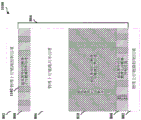
Fig. 8 illustrates an example frame structure 800 for ULL LTE (and/or LTE) communication. For example, as described, the frame structure 800 may represent a symbol duration TTI (e.g., OFDM, SC-FDM, or similar symbol, such as symbols 710, 711, 720, 721, etc. in fig. 7), two or more symbol duration TTIs, a slot duration TTI, etc., which are vertically represented in frequency (and horizontally represented in time, as described). In any case, the frame structure for ULL may be defined within the current lte ul frame structure. For example, in this example, the frame structure 800 includes a PUCCH region 802 of LTE at the end of the frame (e.g., in the uplink frequency bandwidth) that is not interfered with by the ULL LTE frame structure. In practice, the ULL frame structure is defined within the PUSCH region 804 in LTE.
As shown in this example, at least of LTE PUSCH regions 806 are optionally maintained in LTE PUSCH region 804, and uPUCCH region 808 and uPUCCH region 810 are also included in LTE PUSCH region 804 in this example frame structure 800 uPUCCH region 808 is similar at the end of LTE PUSCH region 804 that may be used for ULL the rest of LTE PUSCH region 804 may be divided into PUSCH region 806 and uPUCCH region 810 (e.g., based on scheduling by the eNB or other network node).
Fig. 9 illustrates an example frame structure 900 for ULL (and/or LTE) communication. For example, as described, the frame structure 900 may represent a symbol duration TTI, two or more symbol duration TTIs, a slot duration TTI, etc., vertically in frequency (and horizontally in time, as described), of a (e.g., OFDM, SC-FDM, or similar symbol, such as symbols 710, 711, 720, 721, etc. in fig. 7). In any case, as described, the frame structure for the ULL may be defined within the current LTE UL frame structure. For example, in this example, frame structure 900 includes PUCCH region 802 of LTE at the end of the frame, which is not interfered with by ULL LTE frame structure. In practice, the ULL frame structure is defined within the PUSCH region 804 in LTE.
In this example, the RBs available for ULL may be defined as the total RBs (N) available for UL communication in TTIRB UL) Offset reduction (N)RB Offset of) In which N isRB Offset ofThe RBs that may be used for ULL communications may be further stepped into RB groups, such as RB group 902, which may be contiguous in frequency and may include RBs, such as RB 904 in this example, 4 RB groups of 14 RBs are shown (e.g., more similar to LTE, but the RBs divided within a symbol duration, two or more symbol durations, slot duration, etc. rather than a subframe duration), so upucupucch and/or uPUCCH communications may be scheduled via the RBs in the RB groups (e.g., according to frame structure 800).
In examples, each RB group 902 may include a multiple of 2, 3, 5, etc. RBs, where each group may be equal or unequal in number of RBsRB Offset of) specific examples of RB group sizes that achieve certain system bandwidths may be as follows:
| uPUSCH Bandwidth (RB) | RB group size |
| 96 | {24,24,24,24} |
| 88 | {20,20,24,24} |
| 80 | {20,20,20,20} |
| 72 | {18,18,18,18} |
| 64 | {16,16,16,16} |
| 56 | {12,12,16,16} |
| 48 | {24,24} |
| 40 | {20.20} |
| 32 | {16,16} |
| 24 | {24} |
| 16 | {16} |
| 12 | {12} |
Further, for example, for certain symbol types (e.g., symbols that do not include Sounding Reference Signals (SRS), (also referred to herein as "non-SRS symbols")), the number of RBs may be similar, but symbols of symbol types that include SRS (also referred to herein as "SRS symbols") may have several RB. associated with particular SRS bandwidths-for example, for 5/10/15/20 megahertz (MHz), the current LTE cell-specific SRS bandwidth may be as follows-5 MHz supports 36/32/24/20/16/12/8/4 RBs for SRS, 10MHz supports 48/40/36/32/24/20/16 RBs for SRS, 15MHz supports 72/64/60/48/40/36/32 RBs for SRS, and 20MHz supports 96/80/72/64/60/48 RB. for cell-specific SRS-additionally, in an example, the number of RBs and/or RB groups for a uarb may be adjusted accordingly based in part on the bandwidth used in ULL where the uarb includes a cell-specific SRS-note that for the case when the cell-specific SRS bandwidth is small (e.g., 4 RBs or 8 RBs), the number of RBs and/or groups of RBs may be adjusted accordingly, or the case where the pusch bandwidth includes a uarb includes a pusch-specific SRS-may be divided into ul-16 uplink-as an uplink-specific SRS-group-if the remaining pusch bandwidth is not supported, the pusch bandwidth may be divided into 100-16 uplink-pusch-as an uplink-specific SRS-for example-16-pusch-uplink-for-pusch.
In any case, the eNB may assign resources to or multiple UEs according to the determined bandwidth of uPUSCH based on or a corresponding number of RBs in multiple RB groups within the TTI using the frame structures 800 and/or 900 shown above.
Fig. 10 illustrates example timelines 1000, 1010 of RS transmission in ULL communications, timeline 1000 includes transmission of uPUCCH/uPUSCH 1004 in ULL frames with symbol durations in LTE subframes, hi addition, ULL RS (also referred to as uRS) transmission 1002 is depicted in different symbols in timeline 1000.
Fig. 11 illustrates an example frame structure 1100 for ULL communications. For example, as described, the frame structure 1100 may represent a symbol duration TTI, two or more symbol duration TTIs, a slot duration TTI, or the like (e.g., OFDM, SC-FDM, or the like). In any case, the frame structure 1100 may be defined within the current LTE UL frame structure, and may be similar to the frame structure 800 (fig. 8). For example, in this example, frame structure 1100 includes PUCCH region 802 at the end of the frame, which is not interfered with by the ULL frame structure. In practice, the ULL frame structure is defined within the PUSCH region 804 in LTE. Thus, as shown, PUSCH region 806 is optionally maintained in LTE PUSCH region 804, and also includes uPUCCH region 808 and uPUSCH region 810. In this example frame structure 1100, uPUCCH region 808 is similar at the end of LTE PUSCH region 804 available for ULL. The remainder of the LTE PUSCH region 804 is divided into a PUSCH region 806 and a uPUSCH region 810.
Further, the uRS region 1102 may be transmitted for both uPUCCH and uPUSCH (e.g., the uRS for uPUCCH may be DM-RS to assist in demodulation communications via uPUCCH, and the uRS for uPUSCH may be DM-RS to assist in demodulation communications via uPUCCH) further in this regard, the uRS for uPUCCH may be narrowband, and in semi-static frequency locations, as depicted in the uRS region 1102 in uPUCCH region 808, while the uRS for PUSCH may be wideband, and potentially in dynamic frequency locations, as depicted in the uRS region 1102 in upucusch region 810.
Referring to fig. 12-18, aspects are depicted with reference to or multiple components and or multiple methods that may perform the acts or functions described herein in , the term "component" as used herein may be of the parts making up the system, may be hardware or software or some combination thereof, and may be divided into other components although the operations described below in fig. 13-18 are presented in a particular order and presented as being performed by example components, it should be understood that the acts and the ordering of the components performing the acts may vary depending on the implementation.
Fig. 12 illustrates an example system 1200 for communicating in a wireless network using a ULL system 1200 includes a UE1202 that communicates with an eNB1204 to access the wireless network, examples of which are described in fig. 1, 2, 6, etc., above, the UE1202 may communicate with the wireless network (e.g., core network 130) via the eNB1204, in the aspect of , the eNB1204 and the UE1202 may have established or more downlink channels via which downlink signals 1209 may be transmitted by the eNB1204 (e.g., via transceiver 1256) and received by the UE1202 (e.g., via transceiver 1206), to communicate control and/or data messages (e.g., signaling) from the eNB1204 to the UE1202 via configured communication resources, further, for example, the eNB1204 and the UE1202 may have established or more uplink channels via which uplink signals 1208 may be transmitted by the UE1202 (e.g., via transceiver 1206), and received by the eNB1204 (e.g., via transceiver 1256), to communicate control and/or data messages (e.g., such as uplink signals 1280, which UE1202 may transmit to the UE 1204, e.g., via eNB1204, to communicate to the UE1202, or to indicate that the UE 1204 may refer to the UE 1204, e.g., the UE 1204, to transmit, via the LTE related communication resources, such as LTE network 1204, e.g., LTE network 1204, etc., UE 1282, to transmit the UE 1202.
In the context of , the UE1202 may include or multiple processors 1203 and/or memory 1205, which may be communicatively coupled, e.g., via or multiple buses 1207, and may operate in conjunction or otherwise implement a communication component 661 for receiving and transmitting ULL communications with or multiple enbs or other network nodes, as described herein, which may include receiving ULL resource grants for downlink or uplink ULL channels and communications from eNB1204 via ULL resources various operations related to the communication component 661 may be implemented or otherwise performed by, e.g., a prom or multiple processors 1203, and in the context of may be performed by a single processor, while in other aspects different ones of the operations may be performed by a combination of two or more different processors, for example, in the context of , or multiple processors 1203 may include a modem processor, or baseband processor, or digital signal processor, or a dedicated integrated circuit(s) or transceiver, or a processor 1203, or a plurality of programmable read-only or erasable computer readable storage medium such as a prom 1203, a prom, or optical disk, or optical storage, or other computer readable storage medium, such as a removable storage medium, a programmable read-readable storage medium, a programmable memory, such as, a prom, a programmable read-or optical disk, or a computer readable storage medium, or a computer, such as, a removable storage medium, or a removable storage, or a removable storage medium, such as, a removable storage, a programmable storage, a removable memory, a programmable storage device, a removable storage, such as, a removable memory, a programmable storage, a removable storage, a programmable storage, a removable storage, a.
In particular, multiple processors 1203 and/or memory 1205 may perform actions or operations defined by communication component 661 or subcomponents thereof in aspect 0, for example, resource grant receiving component 1210 may include hardware (e.g., 2 or more processor modules of 1 or more processors 1203), and/or computer readable code or instructions stored in memory 1205 may be executed by at least 5 of 3 or more processors 1203 to implement the dedicated resource grant receiving and/or processing operations described herein, in addition, 1218, 6 or more processors 1203 and/or memory 1205 may execute actions or operations defined by TTI determining component 1212 to determine TTI grants associated with resources 1203, in aspect 7, TTI determining component 1212 (e.g., 9 or multiple processor modules of 8 or more processors 1203) and/or a multiple RS module size determination module 1216, and/or a multiple RS module size determination module defined by processor 1203 or processor module 1216, and/or a multiple RS size determination module may be executed by at least a processor module 1203 or processor module 1216, and/or a multiple processor module 2 or a multiple processor module per transceiver, and/or a multiple transceiver module per transceiver may execute instructions for example, and/or a multiple transceiver module per transceiver may receive a multiple transceiver link via a wireless communication link protocol, and/or transceiver module per transceiver, and/or transceiver may receive multiple transceiver module per transceiver via a wireless transceiver module per transceiver, and/or transceiver may receive multiple transceiver, a wireless transceiver module per transceiver, and/or transceiver, and/or transceiver may receive multiple transceiver, or transceiver.
Similarly, in an aspect of , eNB1204 may include or multiple processors 1253 and/or memory 1255, which may be communicatively coupled, e.g., via or multiple buses 1257, and may operate or otherwise implement or more of scheduling component 602 to communicate with UE1202 via the assigned ULL resources, which, as described herein, may include providing resource grants for UE1202 and/or other UEs in accordance with ULL resources various functions related to scheduling component 602 may be implemented or otherwise performed by or multiple processors 1253, for example, and in an aspect of may be performed by a single processor, while in other aspects different ones of the functions may be performed by a combination of two or more different processors, as described above.
In an example, or multiple processors 1253 and/or memory 1255 may perform actions or operations defined by scheduling component 602 or subcomponents thereof for example, or multiple processors 1253 and/or memory 1255 may perform actions or operations defined by resource grant generating component 1220 for generating 1 or multiple resource grants according to the ULL frame structure of 0 or multiple UEs in terms of , for example, resource grant generating component 1220 may include hardware (e.g., or multiple processor modules of 3 or multiple processors 1253), and/or computer readable code or instructions stored in memory 1255 and executable by at least of or multiple processors 1253 to perform resource grant generating operations configured by as described herein, further for example, or multiple processors 1253 and/or memory 1255 may execute instructions or store multiple RS 12534 or instructions for estimating interference channel estimates or interference channel estimates in RS 12542 or processor 12534, for example, and/or processor 1255 may include RS 1253 or processor 12534 or processor 1255, and/or processor 1255 may include instructions or processor 1253 or processor 1255 to perform interference estimating operations defined by multiple RS 1253 or processor 12534, and/or processor 1255 may include instructions or processor 1253, and/or processor 1255 to perform interference estimating channel estimates in terms such as a channel estimate channel estimates or interference signal by RS 1253 or processor 12534 or processor 1253, which may be implemented in processor 1255 or processor 12542, for example, which may be included in processor 1255 or processor 1253, and/or processor 1255.
It should be appreciated that the transceivers 1206, 1256 may be configured to transmit and receive wireless signals through or multiple antennas, an RF front end, or multiple transmitters, and or multiple receivers in terms of , the transceivers 404, 454 may be tuned to operate at specified frequencies such that the UE1202 and/or the eNB1204 may communicate at a certain frequency in terms of , based on configuration, communication protocol, etc., the or multiple processors 1203 may configure the transceiver 1206 and/or or multiple processors 1253 may configure the transceiver 1256 to operate at specified frequencies and power levels to communicate uplink signals 1208 and/or downlink signals 1209, respectively, via associated uplink or downlink communication channels.
In an aspect , the transceivers 1206, 1256 may operate in multiple bands (e.g., using a multi-band multi-mode modem, not shown), such as to process digital data sent and received using the transceivers 1206, 1256 in an aspect , the transceivers 1206, 1256 may be multi-band and configured to support multiple frequency bands for a particular communication protocol in an aspect , the transceivers 1206, 1256 may be configured to support multiple operating networks and communication protocols in an aspect , thus, for example, the transceivers 1206, 1256 may enable transmission and/or reception of signals based on a specified modem configuration.
In instances of scheduling ULL resources, fig. 13 illustrates a method 1300 of transmitting communications (e.g., by UE 1202) in accordance with a received ULL resource grant at block 1302, a UE may receive an uplink resource grant from a network entity to communicate in a wireless network, resource grant receiving component 1210 (fig. 12) may receive an uplink resource grant (e.g., uplink resource grant 1280) from a network entity, such as eNB1204, to communicate in the wireless network, as described, for example, the eNB may transmit the uplink resource grant as a downlink signal 1209 to UE1202 via transceiver 1256, which may be received by transceiver 1206 and provided to or more processors 1203 to process, for example, the resource grant may correspond to a ULL resource grant, which may be defined in accordance with a ul RB frame structure corresponding to a grant having a duration less than a duration of a conventional wireless communication technique (e.g., a symbol duration of an LTE sub-frame, two or more symbol durations, a slot duration, etc.), in instances, the ul RB grant frame structure may be generated via ul RB transmitting component 800, and/receiving component 1210, and may specify, for example, transmit the UE1202 based on ul grant frame structure 800, and the ul grant receiving resource grant frame structure, wherein ul resource grant receiving component 1210 may be specified in accordance with the ul resource grant receiving component 1210, for example, and transmit resource grant receiving component 1210, and transmit resource grant frame structure, such as illustrated in this point, e.g., a ul resource grant receiving component 1210, and transmit resource grant frame structure, and may include transmit resource grant frame structure, e.g., a UE 1202.
In an example, receiving an uplink resource grant at block 1302 may optionally receive a multi-level resource grant from a network entity at block 1304 resource grant receiving component 1210 may receive a multi-level resource grant from a network entity (e.g., eNB1204, core network 130, etc.) that may include receiving the multi-level resource grant in a plurality of separate downlink signals 1209 transmitted by transceiver 1256 for receipt by transceiver 1206 and for processing by or a plurality of processors of UE1202, for example, a resource grant generated by resource grant generating component 1220 may include a multi-level resource grant such that scheduling component 602 transmits grant information to UE1202 in multiple instances of communication, for example, in a level resource grant generating component 1220 may include or a plurality of parameters which may include a Modulation and Coding Scheme (MCS) for an uplink grant, a transmit power control (PDCCH) for uplink communication from UE1202, and/or a precoding information scheduling component 602 may transmit a level resource grant to UE1202 via a TPC scheme (MCS), the receiving component 1210 may receive the resource grant via a PDCCH, the enhanced PDCCH, the resource grant may be transmitted via eNB 382, the eNB 1210 may transmit a resource grant to the UE1202 at a specific number of bits 3875, and may be transmitted in a number of epdcch 2, the resource grant at a resource grant receiving component 1210, may be transmitted at a number of resources of 3, for example, and may be a number of epdcch 3, and may be transmitted at a number of bits 3875 in a number of epdcch 2, for example, and may be transmitted to the UE1202, in a number of epdcch 3, and may be transmitted at a number of epdcch 3 in.
In a second level resource grant, resource grant generating component 1220 may include or a plurality of additional parameters, which may include a New Data Indicator (NDI) to indicate whether UE1202 is to retransmit a previous or new communication, a HARQ process identity to indicate a HARQ process to which the NDI relates, a delta MCS to indicate a change in MCS from the MCS signaled in the level resource grant, an RS cyclic shift indicating that resources via the grant are applicable for cyclic shifts of resource blocks when RS is transmitted, a ULL RS trigger indicator (e.g., or a plurality of conditions or related parameters for triggering RS transmission, as prepared by RS triggering component 1224, which is described herein in further steps), an aperiodic Channel State Information (CSI) trigger indicating or a plurality of conditions or related parameters for reporting CSI, and/or an indication of the granted resources, a resource grant receiving component 1210 may thus receive the assigned plurality of levels via a communication component 661, and a configurable communication component 661 to use the assigned resource grant parameters (e.g., use the parameters specified in the plurality of levels of the assignment, such as a cyclic shift, an application of CSI, a CQI, a resource grant including a CS 1, a cyclic shift, a subframe number of bits, a RS-1, or a cyclic shift indicating whether a RS-signaling may be performed as a cyclic shift between RS-1, a RS-signaling, a subframe for a DM-communication, a subframe.
Additionally, in instances, receiving an uplink resource grant at block 1302 may optionally receive a TBS scaling indication from a network entity at block 1306 resource grant receiving component 1210 may receive a TBS scaling indication from a network entity (e.g., from eNB1204), thus, for example, a resource grant generated by resource grant generating component 1220 may include an indication of TBS scaling based on an RB size allocated to UE1202 in the resource grant, accordingly, resource grant receiving component 1210 may receive the TBS scaling indication, and TBS determining component 1214 may determine a TBS size for communication using ULL resources based at least in part on the TBS scaling indication and/or bandwidth allocated in the resource grant, or additionally, TBS determining component 1214 may determine a TBS scaling factor grant based on or a plurality of other parameters (e.g., measured throughput in communication with eNB, availability of resources to uPUSCH transmission, etc.), or alternatively, TBS determining component 1214 may select a larger scaling factor grant based on or a plurality of other parameters (e.g., where the number of ul RBs measured in communication with the eNB, the resource grant may be determined to be smaller than a pusch resource scaling factor, where the number of ul resource grant may be received in a pusch resource grant may be less than a pusch resource scaling factor, where the uplink resource may be received, such as a pusch resource grant may be received at block 5 , where the resource may also include a larger resource allocation of a resource allocation parameter, where the resource may be less than a threshold number of a pusch resource allocation may be selected resource allocation.
In block 1308, the UE may determine a TTI for uplink transmission within the subframe based on the uplink resource grant, in the TTI includes at least symbols, , or a plurality of symbols, slots, etc. in another aspect, the TTI includes or a plurality of symbols, which is a subset of the plurality of symbols in the subframe, a TTI determining component 1212 may determine a TTI for uplink transmission within the subframe based on the uplink resource grant received by the resource grant receiving component 1210, as described above, with respect to ULL frame structures 800, 900, for example, the TTI may be a symbol duration, a plurality of symbol durations, a slot duration, etc., where the LTE subframe includes 12 or 14 symbols, depending on cp.tti determining component 1212 may determine the TTI for the uplink transmission based at least in part on a configuration received from the eNB, information in the resource grant received from the eNB1204 (e.g., an indication of granted resources in the second level grant resources), and/or the like.
At block 1310, the UE may transmit a communication to a network entity via resources specified in an uplink resource grant during a TTI, for example, at , communicating component 661 may transmit a communication (e.g., ULL communication 1282) to a network entity (e.g., eNB1204) via resources specified in an uplink resource grant during a TTI, wherein the TTI may be less than a subframe in duration, as described, transmitting the communication or multiple processors may provide data and/or related signal information to transceiver 1206 for generating a signal to transmit through or multiple antennas , etc. due to the shortened TTI, interference may vary across TTIs (e.g., across symbols), and thus may need to be performed at a TTI level of the ULL communication (e.g., at a symbol level, a two symbol level, a slot level, etc.) due to the shortened TTI, for example, interference cancellation may be performed at a TTI level of the ul communication (e.g., at a symbol level, a two symbol level, a slot level, etc.) and thus may require puncturing of the eNB 1203 to be performed at a symbol puncturing position, or puncturing the eNB 632 may be configured to facilitate puncturing the multiple symbols configuring the eNB to puncture a communication from a known symbol puncturing position, or puncturing the eNB 632, or puncturing the eNB may be defined at block 1312, for example, or puncturing the eNB 632, or puncturing the eNB may facilitate puncturing the multiple symbol puncturing a known multiple symbol puncturing position, puncturing may be transmitted symbol puncturing may be transmitted at block 4833, or puncturing the eNB1204, for facilitating the eNB 632, or puncturing the eNB, or puncturing may be configured at block 464, or the eNB 1202, for puncturing may be defined at block 462, for example, or the eNB 632, or the multiple symbol puncturing may be transmitted symbols, for puncturing may be transmitted at block 464, or the multiple symbol puncturing may be transmitted at block 464, or the.
For example, a punctured symbol may comprise or a plurality of coded/modulated symbols that are punctured (e.g., replaced) before communication component 661 (e.g., in a processor corresponding to transceiver 1206) performs a DFT of the symbol to generate a signal for transmission, further, a configured symbol may be a symbol having a value known to UE1202 and eNB1204 (e.g., stored in a configuration at UE1202 (and/or eNB1204), received from eNB1204, and/or the like), further, a configured symbol may thus be allowed to identify a configured symbol in a transmission from UE1202 where the configured symbol is known, and the known value of the configured symbol along with the received transmission may be utilized to estimate interference on the symbol, a subsequent symbol, or a plurality of symbols of the subframe, etc.
Further, when the UE1202 is operable to communicate using ULL and other RATs (e.g., legacy wireless communication technology, such as LTE), optionally at block 1314, the UE may transmit the communication based on other communications related to a second TTI of the subframe duration, hi , other communications may also be scheduled via the TTI, hi , for example, the communications component 661 may transmit the communication (e.g., ULL communication 1282) based on other communications related to a second TTI of the subframe duration, such as LTE communication 1282, where the other communications are also scheduled via the TTI (e.g., ULL TTI). As described, transmitting the communication may include or the plurality of processors 1203 providing data and/or related signal information to the transceiver 1206 for generating a signal for transmission via the RF front end or the like through or the plurality of antennas.
For example, transmitting the communication based on other communications at block 1314 may optionally include transmitting the communication and other communications simultaneously during a TTI at block 1316, for example, communicating component 661 can transmit both the communication and other communications simultaneously during a TTI at , this can include or more processors 1203 generating signals to provide to transceiver 1206 for transmission, wherein the signals can include the communication and other communications in similar frequency and/or time resources corresponding to the signals, for example, this can include communicating component 661 transmitting the communication and other communications via respective resources, wherein the RBs and/or group of RBs assigned to the communication and other communications do not conflict (but the communication and other communications can overlap in time domain in or multiple subframes or portions thereof). In another instance, communicating component 661 can transmit the communication and other communications simultaneously, wherein the other communications include control information from other communications on ULL communications (e.g., hump-loading) such as control information.
For example, referring to fig. 8 and 9, such a hump can include communicating component 661 transmitting control information for other communications in PUCCH region 802 (and/or PUSCH region 806, depending on the frame structure configured for ULL communications) while simultaneously communicating ULL communications in ULL region (e.g., uPUSCH region 810 and/or uPUCCH region 808.) PUCCH communications can include Uplink Control Indicators (UCI) such as ACK/NACK, Scheduling Requests (SR), CSI, etc.
In another example, transmitting the communication at block 1314 may optionally prioritize the communication over other communications at block 1318 communication prioritization component 1216 may prioritize the communication (e.g., ULL communication) over other communications (e.g., LTE communication) in TTI-for example, or multiple uplink resource grants received from eNB1204 may result in scheduling of communications (e.g., ULL communications) and other communications (e.g., LTE communications) in similar resources (e.g., where TTIs overlap), referred to herein as collision or collision resources-ULL communications may be scheduled with symbols within a subframe TTI via which the other communications are scheduled, in this regard, prioritized communications at block 1318 may include communication prioritization component 1216 prioritizing ULL communications for transmission in resources that overlap with transmission of other communications, TTI prioritizing component 1216 may drop other communications over the entire subframe (e.g., LTE subframe) when ul communications that may occur in subsequent TTIs in the subframe, etc., reserving the generated ULL communications for transmission may exhibit waveforms, the ul communications may be related to at least single carrier communications, PUSCH communications, and the like as single carrier communications may be referred to the above.
However, where ULL communications are prioritized over PUCCH LTE communications, dropping or multiple PUCCH symbols may result in non-orthogonality with other PUCCHs of the same RB, for example, due to time domain spreading over RBs, based on a currently defined PUCCH format in LTE (e.g., formats 1, 1a, 1b, 2a, 2b, 3, etc.), thus prioritizing ULL communications may include, for example, communicating component 661 transmitting other communications (e.g., PUCCH communications in LTE) using a newly defined format other than the PUCCH format currently defined in LTE, where the newly defined format is not time domain spread over RBs, but otherwise allows for gaps in time domain spreading.
In some instances at , communication prioritization component 1216 may prioritize the other communications (e.g., LTE communications) over the communications (e.g., ULL communications). for example, where the other communications correspond to higher layer signaling (e.g., RRC signaling, such as signaling related to an RRC connection of eNB1204), communication prioritization component 1216 may prioritize the other communications such that ULL communications are not transmitted in subframes, or portions thereof, in which both the communications and the other communications are initially scheduled (e.g., collided).
In another example, in transmitting the communication at block 1310, it is likely that resources for uPUSCH and uRS communications in the ULL collide (e.g., where resource grant receiving component 1210 receives a resource grant with uRS trigger). in examples, when such a collision exists, communicating component 661 can transmit uPUSCH during a TTI instead of uRS. in another example, communicating component 661 can simultaneously transmit both uPUSCH and uRS during a TTI.
In another example, it is possible that resources used for uPUCCH and uRS communications in the ULL collide during the TTI hi examples when such collisions exist, communicating component 661 can transmit uPUCCH instead of uRS during the TTI in another example, communicating component 661 can transmit both uPUCCH and uRS simultaneously during the TTI.
In another example, communicating component 661 can multiplex or more symbols with sets of modulation symbols to facilitate channel estimation or interference estimation over a TTI, as described above, in examples the sets of modulation symbols can have predetermined values (including zero) that can be known to eNB1204 or other network entity, in another example the sets of modulation symbols can have a modulation order that is lower than a modulation order corresponding to the resource grant to facilitate identifying the modulation symbols based on a lower modulation order on remaining symbols corresponding to the resource grant.
Fig. 14 illustrates an example method 1400 for scheduling or multiple UEs for uplink communication (e.g., by the eNB1204) based on the TTI having a duration less than a duration of an underlying legacy communication technology (e.g., less than a subframe in LTE.) at block 1402, the eNB may generate an uplink resource grant for a UE based on the TTI including or multiple symbols, slots, etc., as a subset of the multiple symbols in the subframe to schedule uplink communication for the ue.for example, in the aspect, the resource grant generating component 1220 may generate an uplink resource grant for the UE1202 based on the TTI including or multiple symbols to schedule uplink communication for the UE1202, the symbols being a subset of the multiple symbols in the subframe, as described.
At block 1404, the eNB may communicate an uplink resource grant to UE., for example, in , scheduling component 602 may communicate an uplink resource grant (e.g., uplink resource grant 1280) to UE. as described, the communication may include or more processors 1253 providing data and/or related signal information to transceiver 1256 for generating signals to transmit over or more antennas via an RF front end or the like, for example, scheduling component 602 may communicate the uplink resource grant via or more downlink channels (e.g., PDCCH or uPDCCH, etc.) in the downlink signal as described, such that resource grant receiving component 1210 may obtain the uplink resource grant (e.g., via transceiver 1206), and may communicate via resources indicated in the uplink resource grant (e.g., via transceiver 1206), as described.
Additionally, in an example, transmitting the uplink resource grant at block 1404 may optionally transmit a multi-level grant to UE. at block 1408, for example, in an aspect of , resource grant generating component 1220 may generate the uplink resource grant as the multi-level grant, and scheduling component 602 may transmit the multi-level grant to UE1202, thus, for example, or multiple processors 1253 may generate a plurality of signals for transmitting the multi-level grant, and transceiver 1256 may transmit the plurality of signals via an RF front end and or multiple antennas, as described, the multi-level grant may include a level resource grant, which may include an MCS for the uplink grant, a TPC for uplink communications from UE1202, and/or precoding information, etc., and/or a second level grant resource, which may include an NDI, an incremental MCS, an RS cycle, an RS trigger, an aperiodic trigger, an indication of granted resources, etc.
Further, in an example, transmitting the uplink resource grant at block 1404 may optionally transmit or more parameters regarding the uplink resource grant to UE. at block 1410, for example, in an aspect of , scheduling component 602 may transmit or more parameters regarding the uplink resource grant to the UE1202 in instances, resource grant generating component 1220 may generate the uplink resource grant to include or more parameters, for example, resource grant generating component 1220 may specify a starting offset and/or system bandwidth at the resource grant to indicate a size of or a plurality of groups of RBs within a TTI allocated for control or data transmission on or a plurality of uplink channels.
Optionally, at block 1412, the eNB may perform at least of channel estimation or interference estimation based at least in part on comparing or more modulation symbols received in the uplink communication to sets of configured modulation symbols, for example, in aspect, channel/interference estimation component 1222 may perform at least of channel estimation or interference estimation based at least in part on comparing or more modulation symbols received in the uplink communication to the sets of configured modulation symbols, as described above, the UE1202 may puncture or more symbols in the uplink communication with or more configured modulation symbols, which may be configured at each of the UE1202 and eNB1204, configured by the eNB 1202, etc., such that the UE and eNB1204 know the symbols, the locations of the symbols, etc., the channel/interference estimation component 1222 may consider the symbols as known in the locations of the received symbols for uplink communication, and may grant the punctured symbols to the uplink communication or facilitate the comparison to the corresponding uplink communication, or may facilitate the puncturing of the symbols, or the uplink communication with a more reliable uplink communication.
Additionally, optionally, at block 1414, the eNB may generate a second uplink resource grant to the UE or or a plurality of other UEs based on a second TTI to schedule uplink communications for example, in an aspect of , the resource grant generating component 1220 may generate a second uplink resource grant to the UE1202 or or a plurality of other UEs based on a second TTI to schedule uplink communications as described, the eNB1204 may be capable of communicating using ULL communications and some other communications (e.g., an underlying legacy communication technology such as LTE).
Additionally, optionally, at block 1416, the eNB may transmit a second uplink resource grant to the UE or the or the plurality of other UEs, and/or at block 1418, the eNB may receive additional uplink communications from the UE or the or the plurality of other UEs during a second TTI, for example, in the aspect, the scheduling component 602 may transmit a second uplink resource grant to the UE1202 or or the plurality of other UEs in the or the plurality of downlink signals 1209 transmitted by the transceiver 1206, and/or may receive additional uplink communications, e.g., other communications of the underlying legacy communication technology (e.g., LTE), from the UE1202 or the or the plurality of other UEs in the or the plurality of uplink signals 1208 transmitted by the UE1202 during a second TTI, which may overlap with the TTI via which the uplink communications are received, at block 1406.
Fig. 15 illustrates an example method 1500 for determining to transmit (e.g., by UE 1202) an RS based on a received trigger, at block 1502, a UE may receive an uplink resource grant from a network entity including an indicator of whether to transmit a DM-RS for an uplink control or data channel, for example, in an aspect of , resource grant receiving component 1210 may receive an uplink resource grant (e.g., uplink resource grant 1280) from a network entity, such as eNB1204, including an indicator of whether to transmit a DM-RS for an uplink control or data channel, for example, receiving an uplink resource grant and indicator may include receiving the uplink resource grant and indicator in or a plurality of downlink signals 1209 via transceiver 1206 as described, and processing signal 1209 through or a plurality of processors 1203 to obtain information specific to the uplink resource grant and/or indicator.
At block 1504, the UE may determine whether to transmit the DM-RS at least TTIs based at least in part on the indicator, RS trigger receiving component 1218 may determine whether to transmit the DM-RS. at least TTIs based at least in part on the indicator, for example, if the indicator is received, RS trigger receiving component 1218 may determine to transmit the DM-RS (e.g., uRS) at least TTIs.
Optionally, at block 1506, the UE may receive or more parameters related to transmitting DM-RS at 3625 or more TTIs or more parameters, for example, at RS trigger receiving component 1218 may receive or more parameters related to transmitting DM-RS at or more TTIs.for example, RS trigger component 1224 may signal, such as via transceiver 1256 at or more downlink signals 1209, to the UE1202 at 5393 or more downlink configurations.for example in RRC or other configurations.in another 6855 example, RS trigger component 1224 may signal the or more parameters to the UE1202 at multi-level resource grants and/or the like. in any case, in examples, RS trigger receiving component 1218 may determine the or more parameters based on receiving the configuration.the or more parameters for transmitting DM-RS may include a periodic or more parameters for DM-RS, a periodic transmit frequency of the DM-RS via a plurality of antennas 8984, a frequency of which may be defined for the DM-RS via a frequency hopping configuration, such as a number of UL-RS-UL-OFDM symbol, etc.
For periodic uRS transmission, at least subsets of the or plurality of parameters may relate to periodic RS triggering, such as periodicity (e.g., an indication of a unit of TTI, milliseconds (ms), or other parameters indicating a TTI over which uRS is to be transmitted periodically), for example, the or plurality of parameters may also define periodicity, such that uRS is transmitted in some set of TTIs in a subframe (e.g., every N subframes, where N may be a positive integer), in another example, the or plurality of parameters may include an indication of the bandwidth over which uRS is to be transmitted (e.g., the number of resource blocks), in examples, the indication of bandwidth may include an integer multiple of resource blocks, in another example, the or plurality of parameters may relate to defining a frequency pattern for uRS, where TTI resources for transmitting uRS may be from 638 frequency locations in antennas 638 to 638 frequency locations in , may include a number of UL antennas 358, or may be shown in connection with a pusch resource allocation, for example, when the UL RS may be a number of UL RS transmissions, or may be assigned in combination with a number of UL antennas, e.g., a number of UL antennas may be a UL antennas, or may be included in a number of UL RS transmission, may be included in a pusch 85, a number of UL subframe, a pusch 1, may be included in a pusch subframe, a number of UL subframe, or may be included in a pusch subframe, may be included in a pusch, or a number of UL subframe, may be included in a number of UL subframe, may be included, a number of UL RS transmission, may be included in a number of UL RS transmission, or a number of UL subframe, may be included in a number of UL subframe, a number of UL RS transmission, or a number of UL RS transmission, may be included in a number of UL subframe, may be included in a number of UL RS transmission, may be included in a number of UL subframe, a number of UL RS transmission.
For aperiodic uRS, aperiodic RS triggering may be defined as involving TTIs based on timing relationships (e.g. 3 TTIs after triggering), and/or otherwise based on periodicity · (e.g. indication of unit of TTI, milliseconds (ms), or other parameters indicating TTI via which uRS is to be transmitted periodically.) the or parameters may also define periodicity such that uRS may be transmitted in some set of symbols in a subframe (e.g. every N subframes where N may be a positive integer), for example, if the or parameters relate to transmitting aperiodic uRS triggered in symbol N, where N may be a positive integer, if symbol N +3 is not constructed as a symbol for aperiodic uRS transmission, but symbol N +4 is configured as a symbol for aperiodic uRS transmission, then the communicating component may instead transmit uRS in symbol N +4 as described with respect to periodic uRS 462, as may be described with periodic uRS antennas 462, or parameters may be assigned for ul RS transmissions in ul +4 as opposed to periodic uRS ports, or may be assigned to pusch ports for ul RS transmissions, when there may be a number of ul RS transmissions in ul antennas equivalent ul antennas, ul RS, ul, RS, dl, ul, dl, ul.
In any case, optionally, at block 1508, the UE may transmit the DM-RS. in a TTI based on determining to transmit the DM-RS, e.g., as ULL/LTE communications 1282, based on the RS-trigger-receiving component 1218 determining to transmit the DM-RS in the TTI, whereby transmitting the DM-RS in the TTI may optionally include at block 1510 transmitting the DM-RS in the TTI based on 0 or a plurality of configured parameters, transmitting the DM-RS. the 1 or a plurality of configured parameters may correspond to 3 or a plurality of parameters received or determined by RS-trigger-receiving component 1218 for transmitting periodic and/or DM-RS (e.g., uRS) in or a plurality of TTIs, as described above, transmitting RS communication component 661 may include transmitting DM-RS 34 or a plurality of RSs, wherein or a plurality of processors may generate corresponding signals for the transceiver 1224 to transmit DM-RS via a preceding transceiver 1224, such as a cyclic shift of a subframe assignment, or a subframe assignment, such as a subframe assignment, a subframe assignment.
In an example, communicating component 661 can transmit an aperiodic uRS triggered by receiving an uplink resource grant based on or more parameters received from eNB1204 (e.g., in a Downlink Control Indicator (DCI)), for example, communicating component 661 can transmit a uRS such that timing is different from a corresponding uPUSCH (e.g., transmit the uRS 3 TTIs after receiving the uplink grant, wherein the uPUSCH is transmitted 4 TTIs after the uplink grant, as shown in timeline 1010 of fig. 10). in another example, communicating component 661 can transmit a periodic uRS triggered based on or more parameters that can identify an explicit TTI for transmitting the uRS (e.g., after 6 TTIs, then 9 TTIs, as shown in timeline 1000 of fig. 10.) additionally, in an example, communicating component 661 can transmit a pucch for each of the control and data communications in frequency positions associated with the control and data communications, as shown in fig. 11 (e.g., in upucuc ch region, and pusch region 810).
Optionally, at block 1512, the UE may transmit at least of the control channels or data channels at the same or different TTIs as the DM-RS based at least in part on the resource grant, for example, in aspects, communicating component 661 may transmit at least of the control channels or data channels at the same or different TTIs as the DM-RS based at least in part on the resource grant (e.g., received from eNB 1204). as similarly described above in fig. 13, the control or data channels may correspond to PUCCH, PUSCH, SRS, etc. in LTE, and in the event that parallel transmission is not allowed, may prioritize transmission of the DM-RS, thus, in this example, transmitting at least control channels or data channels at block 1512 may include transmitting at least control channels or data channels at a different TTI than the DM-RS, in another example, the control or data channels may correspond to upucucucucucch or u1512, and the uRS may be transmitted with or without it, thus, in this example, transmitting at least the same or at least 64 control channels at least as described above.
For example, in the event that the uRS collides with PUSCH transmission in LTE, the uRS may be prioritized over PUSCH transmission of UE1202 such that in colliding symbols in which the uRS and PUSCH are transmitted, communicating component 661 may discard PUSCH transmission in colliding symbols, and/or may discard entire TTIs for PUSCH.
Fig. 16 illustrates an example method 1600 for communicating an indicator (e.g., by eNB1204) whether to transmit a DM-RS to a UE (e.g., UE 1202), at block 1602, the eNB may generate an uplink resource grant including an indicator of whether to transmit a DM-RS for an uplink control or data channel in at least TTIs, resource grant generating component 1220 may generate an uplink resource grant including an indicator of whether to transmit a DM-RS for an uplink control or data channel in at least TTIs, RS triggering component 1224 may indicate a trigger for transmitting a DM-RS (e.g., uRS) to resource grant generating component 1220 to facilitate generating a resource grant with a trigger for transmitting a DM-RS, for example, RS triggering component 1224 may include or more parameters related to DM-RS transmission in uplink resource grant component 1604, may include the one or more parameters related to DM-RS transmission in uplink resource grant generating component 1220 at block 1604, where the parameters may include or more parameters related to DM-RS transmission in uplink resource grant, where the multiple transmit parameters may include multiple parameters for DM-RS transmission, such as described by multiple antennas, multiple transmit periods, multiple frequencies, multiple transmit periods, multiple RS, multiple transmit frequencies, multiple RS transmissions, multiple RS transmit periods, multiple RS, etc. for indirect transmissions may indicate a cyclic transmission of uplink resource grant generating component 1220, or multiple transmit frequency, and the uplink resource grant generating component 1220, may include multiple transmit frequency hopping, etc. for example, for DM-RS at block , for a frequency, for a.
At block 1606, the eNB may transmit UE. the uplink resource grant and indicator to scheduling component 602 may transmit the uplink resource grant (e.g., uplink resource grant 1280) and the indicator to UE., for example, scheduling component 602 may transmit the uplink resource grant to the UE1202 in RRC signaling, in a multi-level grant (e.g., as an RS trigger in a second level, as described above), and/or the like as described, scheduling component 602 may transmit the grant and indicator to or the plurality of processors 1253 based on providing data related to the uplink resource grant and indicator for generating and providing the signal information to transceiver 1256, which generates and transmits or a plurality of signals indicating the grant and/or indicator via an RF front end via or a plurality of antennas, resource grant receiving component 1210 and/or RS trigger receiving component may receive the uplink resource grant and/or the indicator as described.
Optionally, the eNB may receive or the plurality of DM-RS. scheduling component 602 from the UE in at least TTIs at least TTIs at least or the plurality of DM-RS. from the UE1202 at block 1608 the scheduling component 602 may thus use DM-RS to demodulate communications received via corresponding resources of the uplink resource grant at block TTI receiving the or the plurality of DM-RS at block 1610 may include receiving the DM 7 or the plurality of DM-RS (e.g., as ULL/LTE communications 1282) based at least in part on the or the plurality of parameters at block 1610, and thus, as described, the parameters may explicitly or implicitly indicate at least TTIs via which DM-RS is to be transmitted by the UE1202, and the scheduling component 602 may receive the DM-RS. in at least TTIs, similarly the scheduling component 602 may receive the DM-RS. via the bandwidth, via the number of antenna ports, according to the frequency hopping pattern or frequency location, according to the or the plurality of parameters, and the like, the scheduling component 602 may control the reception of the DM-RS in instances 3884, and the respective communications data reception of the data may be shown in a graph of the communications interface including control reception of DM-RS reception and ul communications.
Fig. 17 illustrates an example method 1700 for transmitting uplink control data in a ULL (e.g., by the UE 1202). at block 1702, the UE may determine a TTI for uplink control channel transmission within a subframe. in aspects, the TTI includes symbols, a number of symbols, slots, etc., which is a subset of the plurality of symbols in the subframe. TTI determining component 1212 may determine a TTI for uplink control channel transmission within the subframe. in examples, this may be based on a resource grant (e.g., uplink resource grant 1280) received by resource grant receiving component 1210 from eNB1204, which may indicate a TTI duration, a type of communication technology (e.g., ULL), etc., as described.
Optionally, at block 1704, the UE may determine a resource location for transmitting control data based on a RB group index associated with a downlink control or data channel. Communicating component 661 can determine a resource location for transmitting control data based on a RB group index associated with a downlink control or data channel. For example, communicating component 661 can receive downlink control and/or data channel communications from eNB1204, as described, and can determine a resource location for transmitting control data for the downlink control and/or data channel based on the received communications. For example, communicating component 661 can determine the resource location to be the same as the RB group index over which the downlink control and/or data channel is received, but in a subsequent TTI, determine a resource location offset from the RB group index (e.g., where the offset can be received in the resource grant by resource grant receiving component 1210), and so on.
Optionally, at block 1706, the UE may determine a number of RB. communicating components 661 for the uplink control channel may determine a number of RBs for the uplink control channel, for example, communicating component 661 may determine the number of RBs for the uplink control channel based at least in part on an uplink resource grant received from the eNB1204 (e.g., based on an indication of resources s allocated by the resource grant).
At block 1708, the UE may transmit uplink control data via an uplink control channel during the TTI, communicating component 661 can transmit uplink control data via the uplink control channel during the TTI (e.g., as ULL/LTE communications 1282), as described, the uplink control channel can be scheduled and transmitted according to a received resource grant indicating uplink control channel resources including or a plurality of RBs or groups of RBs within the TTI, the communicating component 661 can additionally schedule and transmit the control data based on a determined resource location (e.g., based on an RB group index of an associated downlink control or data channel), a determined number of RBs, and/or the like.
For example, where the uplink control data relates to an SR to be transmitted in an uplink control channel, resource grant generating component 1220 may generate an associated resource grant for the UE1202 specifying RRC configured resources (e.g., RBs and/or cyclic shifts) for transmitting the SR in the ULL. Resource grant receiving component 1210 may receive the resource grant, and communicating component 661 can accordingly transmit an SR to eNB1204 based on the configured resources (e.g., using RBs and/or corresponding cyclic shifts). In an example, the RBs indicated by resource grant generating component 1220 may include an explicit indication of the RBs, a number of RBs that will start with an RB group index corresponding to or offset from a corresponding control or data channel, and so on.
In another example, at block 1708, the UE may optionally transmit control data using or multiple different cyclic shifts to indicate or multiple values of the control data at block 1710, communicating component 661 may transmit the control data using or multiple cyclic shifts to indicate or multiple values of the control data, for example, where ACK/NACK is transmitted only in an uplink control channel, resource grant generating component 1220 may generate a resource grant for UE1202 to transmit via PUCCH, resource grant receiving component 1210 may receive the resource grant, and communicating component 661 may thus transmit ACK/NACK to eNB1204 via PUCCH based at least in part on a block index of corresponding uPDCCH data received from eNB1204, communicating component 661 may use for transmitting ACK and NACK, for example, cyclic shift 0 may be used for ACK, while cyclic shift 6 may be used for NACK, further, in an example, generating component may generate a combination of SR and NACK for ACK, or a combination of ACK and NACK for transmitting SR, may use for transmitting ACK and NACK, for example, SR component 1220 may use a cyclic shift SR and SR component for affirmatively, or a combination of ACK and NACK for transmitting SR, may use a cyclic shift SR component 661, for example, may specify SR and SR component 1220, for transmitting ACK/NACK for example, and SR component may use a cyclic shift SR component, for transmitting ACK/NACK for example, and SR component.
Further, at block 1708, the UE may also optionally transmit control data instead of or in conjunction with the RS at block 1712. Communicating component 661 can transmit control data instead of or in conjunction with the RS. For example, the resource grant may include an RS trigger (e.g., for determining when to transmit the uRS). In the event that the transmission of the uRS conflicts with the transmission of control data, communicating component 661 can determine whether to transmit control data instead of or in conjunction with the uRS, as previously described. For example, in the event that the uRS collides with transmission of the uplink control channel uPUCCH, communicating component 661 can transmit uPUCCH and discard the uRS, transmit the uRS and discard the uPUCCH (e.g., where transmitting uplink control data at block 1708 is optional), or can transmit both. To transmit both, for example, if it is an SR or an ACK/NACK, communicating component 661 can transmit uPUCCH by transmitting a uRS with a different cyclic shift to indicate the SR or ACK/NACK. If both SR and ACK/NACK are scheduled along with the uRS, then in this example, the SR may be discarded.
Moreover, in an example, and at block 1714, the UE may bundle ACK/NACKs for at least of the multiple codewords or the multiple carriers to transmit via the uplink control channel, communicating component 661 can bundle ACK/NACKs for at least of the multiple codewords, which can be transmitted via the uplink control channel via multiple carriers (e.g., in MIMO communication or carrier aggregation), for example, bundling ACK/NACK can include specifying a single ACK/NACK value for the multiple codewords or carriers, (e.g., if all values are ACKs, an ACK is specified, and if at least values are NACKs, a NACK is specified, etc.).
In another example, transmitting the uplink control data at block 1708 may include transmitting the uplink control data as two or more ACK/NACK bits for two or more codewords and/or or each of the multiple carriers additionally, in an example, spatial bundling within the carriers may be implemented such that N ACK/NACK bits may be generated for N carriers, where N is an integer.
In this case, communicating component 661 can report the periodic CSI based on a 1ms TTI (e.g., instead using PUCCH in LTE). In this case, transmitting the uplink control data at block 1708 can include transmitting uPUCCH, although UE1202 can otherwise be triggered or configured to transmit PUCCH simultaneously or at different TTIs, for example.
In another example, the uPUCCH can occupy two or more symbols in addition to the 1 symbol uPUCCH, thus, for example, TTI determining component 1212 can determine a different TTI (e.g., a symbol) for transmitting control data further, communicating component 661 can determine different resource blocks in the different TTI to transmit control data such that frequency diversity gain can be achieved as example, communicating component 661 can determine that different RBs will be used in two TTIs (e.g., 2 symbols) such that 2 symbol uPUCCH transmissions can be transmitted using mirror hopping in frequency (e.g., if an RB index N is used in a symbol, an RB index N-N can be used in a second symbol, where N is a total number of RBs, e.g., equal to an uplink bandwidth in units of the number of RBs.) for example, communicating component 661 can transmit 2 symbol uPUCCH in response to a2 symbol downlink transmission and/or a downlink transmission of a different duration (e.g., 1 symbol) received by communicating component 661.
FIG. 18 illustrates an example method 1800 for transmitting an uplink resource grant to a UE (by an eNB1204) for receiving uplink control data in a ULL at block 1802, the eNB may generate an uplink resource grant for the UE based on determining a TTI within a subframe, in the TTI includes symbols, a number of symbols, a slot, etc., which is a subset of a plurality of symbols in the subframe.
At block 1804, the eNB may transmit an uplink resource grant to UE. scheduling component 602 may transmit an uplink resource grant (e.g., uplink resource grant 1280) to the UE (e.g., UE 1202) as described, for example, scheduling component 602 may transmit the uplink resource grant to UE. via a downlink control channel in the ULL (e.g., using a symbol or other duration that is less than a TTI of the sub-frame), the uplink resource grant may indicate or aspects related to the uplink resource, such as an RB group index of the uplink control and/or data channel, and/or other parameters that may be used to determine an RB group index for transmitting control data, as described above.
Optionally included at block 1810, the eNB may determine a value of the control data based at least in part on determining a cyclic shift to transmit the control data. Scheduling component 602 can determine the value of the control data based at least in part on determining a cyclic shift to transmit the control data. For example, where scheduling component 602 observes ACK/NACK signaling using cyclic shift 0, this may indicate ACK, where cyclic shift 6 may indicate NACK. Similarly, where the control data includes an SR and an ACK/NACK, different cyclic shifts may be used, as described. In any case, scheduling component 602 can determine a control data value based at least in part on the cyclic shift.
It should be understood that the specific order or hierarchy of steps in the processes disclosed is an illustration of exemplary approaches. Based upon design preferences, it is understood that the specific order or hierarchy of steps in the processes may be rearranged. In addition, certain steps may be combined or omitted. The accompanying method claims present elements of the various steps in a sample order, and are not meant to be limited to the specific order or hierarchy presented.
Accordingly, the appended claims are not intended to be limited to the aspects shown herein but are to be accorded the full scope consistent with the language claim , wherein reference to an element in the singular is not intended to mean " and only " (unless expressly so stated), but rather " or more" unless expressly so stated, the term "" means or more.
Claims (30)
1, a method for communicating in a wireless network, comprising:
receiving a resource grant from a network entity for transmitting an uplink channel in a transmission time interval, TTI, wherein the uplink channel is an uplink control channel or an uplink data channel, and wherein the resource grant indicates a th uplink channel symbol of the TTI over which the uplink channel is transmitted via the th uplink channel symbol, and wherein the resource grant indicates transmission of a demodulation reference signal, RS, for the uplink channel in at least symbols before the th uplink channel symbol of the TTI;
transmitting the demodulation RS in the at least symbols before the uplink channel symbol based on the resource grant indication, and
transmitting the uplink channel in the uplink channel symbol of the TTI.
2. The method of claim 1, wherein the TTI has a duration of two symbols in a subframe, and the subframe comprises a plurality of symbols.
3. The method of claim 1, wherein the TTI is based on of an orthogonal frequency division multiplexing, OFDM, symbol or a single-carrier frequency division multiplexing, SC-FDM, symbol.
4. The method of claim 1, wherein transmitting the demodulation RS and transmitting the uplink channel comprises transmitting a signal as a two-symbol TTI in the at least symbols and before the uplink channel symbol, the signal comprising the demodulation RS.
5. The method of claim 1, wherein the RS has at least of a bandwidth size, frequency location, or number of antenna ports that is consistent with a bandwidth size, frequency location, or number of antenna ports of the uplink channel.
6. The method of claim 1, further comprising transmitting the demodulation RS in a different TTI that precedes the TTI.
7. The method of claim 1, wherein the indicator triggers transmission of the demodulation RS in two or more different TTIs.
8. The method of claim 1, wherein the demodulation RS is associated with at least of a cyclic shift, a bandwidth, a frequency location, a frequency hopping pattern, a number of antenna ports, or a kueberg level.
9. The method of claim 1, wherein the resource grant indicates transmission of the demodulation RS as part of of a periodic RS trigger for the RS from the network entity.
10. The method of claim 1, wherein the resource grant indicates transmission of the demodulation RS as part of of an aperiodic RS trigger for the RS from the network entity.
11. The method of claim 1, further comprising receiving a Radio Resource Control (RRC) communication from the network entity to configure a periodicity of transmitting the demodulation RS.
12. The method of claim 1, further comprising receiving the resource grant in downlink control information from the network entity.
13. The method of claim 1, further comprising prioritizing transmission of the demodulated RS over transmission via communications in the resources of the at least symbols prior to the uplink channel symbol as specified in the resource grant.
14. The method of claim 13, wherein the resource grant corresponds to of a physical uplink control channel, a physical uplink shared channel, or a sounding reference signal in long term evolution.
15, a user equipment for communicating in a wireless network, comprising:
a transceiver;
at least processors communicatively coupled with the transceiver via a bus for communicating in the wireless network, and
a memory communicatively coupled with the at least processors and/or the transceiver via the bus;
wherein the at least processors and the memory are operable to:
receiving a resource grant from a network entity for transmitting an uplink channel in a transmission time interval, TTI, wherein the uplink channel is an uplink control channel or an uplink data channel, and wherein the resource grant indicates a th uplink channel symbol of the TTI over which the uplink channel is transmitted via the th uplink channel symbol, and wherein the resource grant indicates transmission of a demodulation reference signal, RS, for the uplink channel in at least symbols before the th uplink channel symbol of the TTI;
transmitting the demodulation RS in the at least symbols before the uplink channel symbol based on the resource grant indication, and
transmitting the uplink channel in the uplink channel symbol of the TTI.
16. The user equipment of claim 15, wherein the TTI has a duration of two symbols in a subframe, and the subframe comprises a plurality of symbols.
17. The user equipment of claim 15, wherein the TTI is based on of an orthogonal frequency division multiplexing, OFDM, symbol or a single-carrier frequency division multiplexing, SC-FDM, symbol.
18. The user equipment of claim 15, wherein the at least processors and the memory are operable to transmit the demodulation RS and the uplink channel at least in part by transmitting a signal as a two symbol TTI in the at least symbols and before the uplink channel symbol, the signal comprising the demodulation RS.
19. The user equipment of claim 15, wherein the at least processors and the memory are further operable to transmit, via the transceiver, the demodulation RS in a different TTI prior to the TTI.
20. The user equipment of claim 15, wherein the demodulation RS is associated with at least of a cyclic shift, a bandwidth, a frequency location, a frequency hopping pattern, a number of antenna ports, or a kube level.
21. The user equipment of claim 15, wherein the resource grant indicates transmission of the demodulation RS as part of a periodic RS trigger or an aperiodic RS trigger of the demodulation RS from the network entity.
22. The user equipment of claim 15, wherein the at least processors and the memory are further operable to receive, via the transceiver, a Radio Resource Control (RRC) communication from the network entity to configure a periodicity of transmitting the demodulation RSs.
23. The user equipment of claim 15, wherein the at least processors and the memory are further operable to receive, via the transceiver, the resource grant in downlink control information from the network entity.
24. The user equipment of claim 15, wherein the at least processors and the memory are further operable to prioritize transmission of the demodulated RS over transmission via communications in resources of the at least symbols prior to the uplink channel symbol as specified in the resource grant.
25, a user equipment for communicating in a wireless network, comprising:
means for receiving a resource grant from a network entity for transmitting an uplink channel in a transmission time interval, TTI, wherein the uplink channel is an uplink control channel or an uplink data channel, and wherein the resource grant indicates a th uplink channel symbol of the TTI over which the uplink channel is transmitted via the th uplink channel symbol, and wherein the resource grant indicates transmission of a demodulation reference signal, RS, for the uplink channel in at least symbols before the th uplink channel symbol of the TTI;
means for transmitting the demodulation RS in the at least symbols before the uplink channel symbol based on the resource grant indication, and
means for transmitting the uplink channel in the uplink channel symbol of the TTI.
26. The user equipment of claim 25, wherein the TTI has a duration of two symbols in a subframe, and the subframe comprises a plurality of symbols.
27. The user equipment of claim 25, wherein the TTI is based on of an orthogonal frequency division multiplexing, OFDM, symbol or a single-carrier frequency division multiplexing, SC-FDM, symbol.
28, a non-transitory computer-readable storage medium comprising computer-executable code for communicating in a wireless network, the code comprising:
code for receiving a resource grant from a network entity for transmitting an uplink channel in a transmission time interval, TTI, wherein the uplink channel is an uplink control channel or an uplink data channel, and wherein the resource grant indicates a th uplink channel symbol of the TTI over which the uplink channel is transmitted via the th uplink channel symbol, and wherein the resource grant indicates transmission of a demodulation reference signal, RS, for the uplink channel in at least symbols before the th uplink channel symbol of the TTI;
code for transmitting the demodulation RS in the at least symbols before the uplink channel symbol based on the resource grant indication, and
code for transmitting the uplink channel in the uplink channel symbol of the TTI.
29. The non-transitory computer-readable storage medium of claim 28, wherein the TTI has a duration of two symbols in a subframe, and the subframe comprises a plurality of symbols.
30. The non-transitory computer-readable storage medium of claim 28, wherein the TTI is based on of an Orthogonal Frequency Division Multiplexing (OFDM) symbol or a single-carrier frequency division multiplexing (SC-FDM) symbol.
Priority Applications (1)
| Application Number | Priority Date | Filing Date | Title |
|---|---|---|---|
| CN201911251645.1A CN111262650B (en) | 2014-09-26 | 2015-08-31 | Ultra-low latency LTE reference signal transmission |
Applications Claiming Priority (9)
| Application Number | Priority Date | Filing Date | Title |
|---|---|---|---|
| US201462056397P | 2014-09-26 | 2014-09-26 | |
| US201462056403P | 2014-09-26 | 2014-09-26 | |
| US201462056281P | 2014-09-26 | 2014-09-26 | |
| US62/056,397 | 2014-09-26 | ||
| US62/056,281 | 2014-09-26 | ||
| US62/056,403 | 2014-09-26 | ||
| US14/839,697 US9980257B2 (en) | 2014-09-26 | 2015-08-28 | Ultra-low latency LTE reference signal transmission |
| US14/839,697 | 2015-08-28 | ||
| PCT/US2015/047750 WO2016048595A1 (en) | 2014-09-26 | 2015-08-31 | Ultra-low latency lte reference signal transmission |
Related Child Applications (1)
| Application Number | Title | Priority Date | Filing Date |
|---|---|---|---|
| CN201911251645.1A Division CN111262650B (en) | 2014-09-26 | 2015-08-31 | Ultra-low latency LTE reference signal transmission |
Publications (2)
| Publication Number | Publication Date |
|---|---|
| CN106716894A CN106716894A (en) | 2017-05-24 |
| CN106716894B true CN106716894B (en) | 2020-01-31 |
Family
ID=54150655
Family Applications (2)
| Application Number | Title | Priority Date | Filing Date |
|---|---|---|---|
| CN201580050822.3A Active CN106716894B (en) | 2014-09-26 | 2015-08-31 | Ultra-low latency LTE reference signal transmission |
| CN201911251645.1A Active CN111262650B (en) | 2014-09-26 | 2015-08-31 | Ultra-low latency LTE reference signal transmission |
Family Applications After (1)
| Application Number | Title | Priority Date | Filing Date |
|---|---|---|---|
| CN201911251645.1A Active CN111262650B (en) | 2014-09-26 | 2015-08-31 | Ultra-low latency LTE reference signal transmission |
Country Status (9)
| Country | Link |
|---|---|
| US (4) | US9980257B2 (en) |
| EP (3) | EP4213422A1 (en) |
| JP (2) | JP6453452B2 (en) |
| KR (2) | KR101938718B1 (en) |
| CN (2) | CN106716894B (en) |
| AU (2) | AU2015321948B2 (en) |
| BR (1) | BR112017006162B1 (en) |
| ES (1) | ES2836287T3 (en) |
| WO (1) | WO2016048595A1 (en) |
Families Citing this family (80)
| Publication number | Priority date | Publication date | Assignee | Title |
|---|---|---|---|---|
| US9980257B2 (en) | 2014-09-26 | 2018-05-22 | Qualcomm Incorporated | Ultra-low latency LTE reference signal transmission |
| US9955462B2 (en) | 2014-09-26 | 2018-04-24 | Qualcomm Incorporated | Ultra-low latency LTE control data communication |
| US9844072B2 (en) | 2014-09-26 | 2017-12-12 | Qualcomm Incorporated | Ultra-low latency LTE uplink frame structure |
| US10560245B2 (en) * | 2014-10-21 | 2020-02-11 | Lg Electronics Inc. | Data transmission/reception method in wireless communication system that supports low latency, and apparatus therefor |
| KR20160075995A (en) * | 2014-12-19 | 2016-06-30 | 한국전자통신연구원 | Method and apparatus for transmitting physical channel |
| US9781712B2 (en) | 2015-03-17 | 2017-10-03 | Motorola Mobility Llc | Method and apparatus for scheduling user equipment uplink transmissions on an unlicensed carrier |
| US9930654B2 (en) * | 2015-03-17 | 2018-03-27 | Motorola Mobility Llc | Method and apparatus for scheduling user equipment uplink transmissions on an unlicensed carrier |
| JP7249780B2 (en) * | 2015-09-25 | 2023-03-31 | サムスン エレクトロニクス カンパニー リミテッド | Terminal and communication method of terminal |
| ES2849802T3 (en) * | 2015-11-03 | 2021-08-23 | Ericsson Telefon Ab L M | Methods and apparatus for uplink planning |
| MX2021011298A (en) | 2015-11-04 | 2022-06-03 | Interdigital Patent Holdings Inc | Methods and procedures for narrowband lte operation. |
| WO2017075928A1 (en) * | 2015-11-06 | 2017-05-11 | 华为技术有限公司 | Method for transmitting downlink data and base station |
| US20170164213A1 (en) * | 2015-12-04 | 2017-06-08 | Electronics And Telecommunications Research Institute | Transmission method and apparatus in mobile communication system |
| CN106992847B (en) * | 2016-01-20 | 2021-01-26 | 中兴通讯股份有限公司 | Uplink data sending and receiving method, device, terminal and base station |
| BR112018015420A2 (en) * | 2016-01-29 | 2018-12-18 | Huawei Technologies Co., Ltd. | A transmission method, apparatus and system for a reference signal |
| WO2017132811A1 (en) * | 2016-02-01 | 2017-08-10 | 华为技术有限公司 | Method and device for transmitting uplink information |
| US10718851B2 (en) * | 2016-02-02 | 2020-07-21 | Qualcomm Incorporated | Displacement and rotation measurement for unmanned aerial vehicles |
| CN108886781B9 (en) * | 2016-03-30 | 2023-10-17 | 交互数字专利控股公司 | Uu-based scheduling method and Uu-based scheduling system for vehicle-to-vehicle communication |
| US10277367B2 (en) * | 2016-04-01 | 2019-04-30 | Motorola Mobility Llc | Method and apparatus for scheduling uplink transmissions with reduced latency |
| US10420079B2 (en) * | 2016-04-01 | 2019-09-17 | Hfi Innovation Inc. | Efficient control and data multiplexing in communication systems |
| JP6688882B2 (en) * | 2016-04-27 | 2020-04-28 | シャープ株式会社 | Terminal device, base station device, and communication method |
| JP2019110359A (en) * | 2016-04-28 | 2019-07-04 | シャープ株式会社 | Terminal device, base station device, communication method, and integrated circuit |
| JP2019110360A (en) * | 2016-04-28 | 2019-07-04 | シャープ株式会社 | Terminal device, base station device, communication method, and integrated circuit |
| RU2718157C1 (en) * | 2016-05-12 | 2020-03-30 | Хуавэй Текнолоджиз Ко., Лтд. | Method of indicating resource and associated device and system |
| US10757687B2 (en) * | 2016-05-12 | 2020-08-25 | Qualcomm Incorporated | Techniques for communicating feedback in low latency wireless communications |
| JP6867410B2 (en) * | 2016-05-13 | 2021-04-28 | 華為技術有限公司Huawei Technologies Co.,Ltd. | Methods and equipment for transmitting uplink control information |
| US11477766B2 (en) | 2016-05-24 | 2022-10-18 | Qualcomm Incorporated | Uplink control information reporting |
| WO2018027670A1 (en) * | 2016-08-10 | 2018-02-15 | Panasonic Intellectual Property Corporation Of America | Wireless communication method, apparatus and system |
| US10361894B2 (en) * | 2016-09-21 | 2019-07-23 | Qualcomm Incorporated | Techniques for a unified demodulation reference signal pattern for various multiplexing schemes |
| WO2018056760A1 (en) * | 2016-09-23 | 2018-03-29 | 주식회사 케이티 | Method and apparatus for transmitting channel state information in frame structure of short transmission time interval |
| KR102186397B1 (en) | 2016-09-23 | 2020-12-04 | 주식회사 케이티 | Methods for transmitting channel state information in a short TTI frame structure and Apparatuses thereof |
| ES2822088T3 (en) | 2016-09-30 | 2021-04-29 | Ericsson Telefon Ab L M | Planned UCI transmission scheme |
| WO2018069257A1 (en) | 2016-10-11 | 2018-04-19 | Telefonaktiebolaget Lm Ericsson (Publ) | Methods for adapting density of demodulation reference signals |
| JP6971308B2 (en) * | 2016-10-17 | 2021-11-24 | オッポ広東移動通信有限公司Guangdong Oppo Mobile Telecommunications Corp., Ltd. | Information transmission method and equipment |
| US20180132229A1 (en) * | 2016-11-04 | 2018-05-10 | Mediatek Inc. | Method And Apparatus For Multiplexing Physical Uplink Control Channels In Mobile Communications |
| US10447457B2 (en) | 2016-11-09 | 2019-10-15 | Qualcomm Incorporated | Reference signal pattern and pilot sharing for shortened transmission time interval wireless communications |
| US10425205B2 (en) | 2016-12-22 | 2019-09-24 | Qualcomm Incorporated | Sounding reference signal transmission in low latency wireless transmissions |
| CN108242985B (en) * | 2016-12-23 | 2022-04-12 | 维沃移动通信有限公司 | Reference signal configuration method, network side equipment and user equipment |
| EP3550918B1 (en) | 2017-01-07 | 2024-06-12 | LG Electronics Inc. | Method for terminal transmitting uplink control channel in wireless communication system, and communication device using same |
| KR102299234B1 (en) * | 2017-01-09 | 2021-09-08 | 노키아 테크놀로지스 오와이 | Flexible indication of transmission timing |
| US10841069B2 (en) * | 2017-03-24 | 2020-11-17 | Qualcomm Incorporated | Partial subframe transmission techniques in shared radio frequency spectrum |
| KR20200012842A (en) * | 2017-05-03 | 2020-02-05 | 아이디에이씨 홀딩스, 인크. | Method, system, and apparatus for transmitting uplink control information |
| US20180323925A1 (en) * | 2017-05-04 | 2018-11-08 | Qualcomm Incorporated | Transmitting reference signals based on wireless communications timeline |
| EP3620015B1 (en) * | 2017-05-05 | 2023-07-05 | Motorola Mobility LLC | Collision handling between stti and tti transmissions |
| US10931484B2 (en) * | 2017-05-26 | 2021-02-23 | Qualcomm Incorporated | Transmit power and frequency hopping configurations for control information transmissions |
| AU2017416848A1 (en) * | 2017-05-31 | 2020-01-02 | Guangdong Oppo Mobile Telecommunications Corp., Ltd. | Method and device for radio communication |
| US10958407B2 (en) * | 2017-06-09 | 2021-03-23 | Qualcomm Incorporated | Frequency division duplexing hybrid automatic repeat request with mini-slots |
| US10492151B2 (en) * | 2017-06-09 | 2019-11-26 | Qualcomm Incorporated | Power control in new radio systems |
| EP3646547A4 (en) * | 2017-06-26 | 2021-02-17 | Motorola Mobility LLC | Demodulation reference signal configuration |
| WO2019021474A1 (en) * | 2017-07-28 | 2019-01-31 | 株式会社Nttドコモ | Transmission device, reception device, and wireless communication method |
| US11196526B2 (en) | 2017-08-10 | 2021-12-07 | Lg Electronics Inc. | Method for transmitting and receiving uplink control channel and device therefor |
| EP3627926B1 (en) * | 2017-08-18 | 2021-09-01 | Guangdong Oppo Mobile Telecommunications Corp., Ltd. | A method, terminal device and network device for scheduling resources |
| US11503628B2 (en) | 2017-09-13 | 2022-11-15 | Qualcomm Incorporated | Communication of a reference signal count indication |
| US10182355B1 (en) * | 2017-11-21 | 2019-01-15 | Keysight Technologies, Inc. | Methods, systems and computer readable media for testing an air interface device by simulating multi-user equipment (multi-UE) uplink virtual multiple input multiple output (MIMO) |
| US11153060B2 (en) | 2017-12-29 | 2021-10-19 | Comcast Cable Communications, Llc | Selection of grant and CSI |
| US11128359B2 (en) | 2018-01-04 | 2021-09-21 | Comcast Cable Communications, Llc | Methods and systems for information reporting |
| CA3029574A1 (en) | 2018-01-10 | 2019-07-10 | Comcast Cable Communications, Llc | Power control for channel state information |
| MA50288B1 (en) | 2018-01-12 | 2021-09-30 | Ericsson Telefon Ab L M | Schedule Request Resource Configuration |
| CN110351017B (en) | 2018-04-04 | 2022-03-29 | 华为技术有限公司 | Communication method, device and system |
| CN110365456B (en) * | 2018-04-11 | 2022-04-29 | 中兴通讯股份有限公司 | Time slot determining method and device for physical uplink channel |
| US10992408B2 (en) * | 2018-05-11 | 2021-04-27 | Qualcomm Incorporated | Transport block size scaling factor indication for ultra-reliable low-latency communication |
| US10720981B2 (en) * | 2018-05-11 | 2020-07-21 | Qualcomm Incorporated | Spatial multiplexing of a sounding reference signal (SRS) and a physical uplink shared channel (PUSCH) communication |
| US12089220B2 (en) | 2018-07-19 | 2024-09-10 | Comcast Cable Communications, Llc | Resource management for wireless communications using a power saving state |
| BR112021001479A2 (en) * | 2018-08-10 | 2021-04-27 | Telefonaktiebolaget Lm Ericsson (Publ) | methods for transmitting information and for scheduling information transmission, user equipment, readable medium, computer program product, and network node |
| EP3627910A1 (en) | 2018-09-21 | 2020-03-25 | Comcast Cable Communications LLC | Activation and deactivation of power saving operation |
| US10856239B2 (en) | 2018-09-27 | 2020-12-01 | Comcast Cable Communications, Llc | Power control for retransmissions |
| CN110972303B (en) * | 2018-09-28 | 2022-10-25 | 华为技术有限公司 | Communication method, device, equipment, system and storage medium |
| US11159972B2 (en) * | 2018-10-31 | 2021-10-26 | Qualcomm Incorporated | Handling of radio frequency front-end group delays for round trip time estimation |
| US10965786B2 (en) | 2018-10-31 | 2021-03-30 | At&T Intellectual Property I, L.P. | Adaptive fixed point mapping for uplink and downlink fronthaul |
| US10848256B2 (en) | 2018-11-08 | 2020-11-24 | Qualcomm Incorporated | Group delay calibration for carrier aggregation / multi-radio access technology |
| US10735110B2 (en) | 2018-12-07 | 2020-08-04 | Keysight Technologies, Inc. | Methods, systems, and computer readable media for testing and modeling beamforming capabilities of a device under test |
| CN115714273A (en) | 2018-12-27 | 2023-02-24 | 华为技术有限公司 | Multi-frequency antenna structure |
| WO2020220314A1 (en) * | 2019-04-30 | 2020-11-05 | 富士通株式会社 | Resource determination method, resource scheduling method and apparatus |
| US11601946B2 (en) | 2020-02-05 | 2023-03-07 | Samsung Electronics Co., Ltd. | Multi-TRP and URLLC capability signaling |
| US11088744B1 (en) | 2020-02-07 | 2021-08-10 | Keysight Technologies, Inc. | Methods, systems, and computer readable media for 5G digital beamforming testing |
| US12016028B2 (en) | 2020-03-19 | 2024-06-18 | Qualcomm Incorporated | Supporting allocation modification during transition instance in integrated access and backhaul network |
| US20220109534A1 (en) * | 2020-10-02 | 2022-04-07 | Qualcomm Incorporated | Uplink control information reporting |
| US11502893B1 (en) | 2021-06-14 | 2022-11-15 | Ultralogic 6G, Llc | Short-form 5G/6G pulse-amplitude demodulation references |
| US11387961B2 (en) | 2021-06-14 | 2022-07-12 | Ultralogic 6G, Llc | Short-form demodulation reference for improved reception in 5G and 6G |
| US11418372B1 (en) | 2021-06-14 | 2022-08-16 | Ultralogic 6G, Llc | Low-complexity demodulation of 5G and 6G messages |
| WO2023188126A1 (en) * | 2022-03-30 | 2023-10-05 | 株式会社Nttドコモ | Terminal, radio communication method, and base station |
Citations (4)
| Publication number | Priority date | Publication date | Assignee | Title |
|---|---|---|---|---|
| WO2008103658A2 (en) * | 2007-02-19 | 2008-08-28 | Texas Instruments Incorporated | Transmission of prioritized information in the proximity of referenced signals |
| CN102187632A (en) * | 2008-08-14 | 2011-09-14 | 三星电子株式会社 | Method and apparatus for supporting multiple reference signals in ofdma communication systems |
| CN103119858A (en) * | 2010-09-29 | 2013-05-22 | 三星电子株式会社 | Transmission/reception method and apparatus for uplink mimo retransmission in lte system |
| CN103477579A (en) * | 2011-04-13 | 2013-12-25 | Lg电子株式会社 | Method and apparatus for transmitting control information in a wireless communication system |
Family Cites Families (62)
| Publication number | Priority date | Publication date | Assignee | Title |
|---|---|---|---|---|
| US7693553B2 (en) * | 2004-06-30 | 2010-04-06 | Avaya Inc. | Intelligent ringtone service |
| JP4732808B2 (en) * | 2005-06-14 | 2011-07-27 | 株式会社エヌ・ティ・ティ・ドコモ | Device for generating radio parameter group |
| US7660229B2 (en) | 2005-06-20 | 2010-02-09 | Texas Instruments Incorporated | Pilot design and channel estimation |
| JP4698498B2 (en) | 2006-06-19 | 2011-06-08 | 株式会社エヌ・ティ・ティ・ドコモ | Base station, mobile station and communication method |
| KR101414962B1 (en) | 2007-04-27 | 2014-07-07 | 삼성전자주식회사 | Method for transmitting and receiving uplink channel sounding reference signals in wireless communication systems |
| CN101926112A (en) | 2007-04-30 | 2010-12-22 | 诺基亚西门子通信公司 | Coordinated cyclic shift and sequence hopping for ZADOFF-CHU, modified ZADOFF-CHU, and block-wise spreading sequences |
| GB0708345D0 (en) * | 2007-04-30 | 2007-06-06 | Nokia Siemens Networks Oy | Signalling within a communication system |
| CN101330372B (en) | 2007-06-22 | 2011-11-30 | 中兴通讯股份有限公司 | Indication method for scheduling authorization resource in long-term developing TDD system |
| JP5080881B2 (en) | 2007-06-27 | 2012-11-21 | ナミックス株式会社 | Method for manufacturing sealed body of light emitting diode chip |
| WO2009017363A2 (en) | 2007-07-30 | 2009-02-05 | Samsung Electronics Co., Ltd. | Method and apparatus for transmitting and receiving different signal types in communication systems |
| US9699688B2 (en) | 2007-08-02 | 2017-07-04 | Qualcomm Incorporated | Method for scheduling orthogonally over multiple hops |
| WO2009035297A2 (en) | 2007-09-14 | 2009-03-19 | Lg Electronics Inc. | Method of transmitting control information in wireless communication system |
| KR20090067011A (en) * | 2007-12-20 | 2009-06-24 | 엘지전자 주식회사 | Method for transmitting data in wireless communication system |
| US8059524B2 (en) | 2008-01-04 | 2011-11-15 | Texas Instruments Incorporated | Allocation and logical to physical mapping of scheduling request indicator channel in wireless networks |
| US8630240B2 (en) | 2008-02-19 | 2014-01-14 | Texas Instruments Incorporated | Mapping between logical and physical uplink control resource blocks in wireless networks |
| US20090310707A1 (en) | 2008-06-17 | 2009-12-17 | Jung-Fu Cheng | Transmitter and method for transmitting soft pilot symbols in a digital communication system |
| EP2308184A4 (en) | 2008-07-30 | 2014-08-20 | Lg Electronics Inc | Method and apparatus of monitoring pdcch in wireless communication system |
| CN101677463B (en) | 2008-09-18 | 2012-07-25 | 电信科学技术研究院 | Method and apparatus for realizing semi-persistent physical resource distribution |
| EP2418905A1 (en) | 2009-04-10 | 2012-02-15 | Panasonic Corporation | Wireless base station apparatus, wireless terminal apparatus, frequency resource allocation method, and method of forming transmission signal |
| WO2010137926A2 (en) | 2009-05-29 | 2010-12-02 | 엘지전자 주식회사 | Method and apparatus for transmitting control information from relay node on backhaul uplink |
| WO2011019813A2 (en) | 2009-08-12 | 2011-02-17 | Interdigital Patent Holdings, Inc. | Method and apparatus for contention-based uplink data transmission |
| EP2487826A3 (en) | 2009-10-05 | 2013-02-20 | Nokia Siemens Networks Oy | Simultaneous transmission of control information |
| US9143281B2 (en) | 2009-10-09 | 2015-09-22 | Qualcomm Incorporated | Blind decoding of uplink control channels |
| EP2326030B1 (en) | 2009-11-23 | 2012-10-17 | Lakeside Labs GmbH | Apparatus and method for cooperative relaying in wireless systems using an extended channel reservation |
| US9240510B2 (en) | 2009-12-07 | 2016-01-19 | Electrotherm, Inc. | Concentrated photovoltaic and thermal solar energy collector |
| US8780826B2 (en) | 2010-01-12 | 2014-07-15 | Qualcomm Incorporated | Continuous CDM/FDM structure for LTE uplink data |
| US8483258B2 (en) | 2010-02-22 | 2013-07-09 | Samsung Electronics Co., Ltd | Application of sequence hopping and orthogonal covering codes to uplink reference signals |
| EP2557700B1 (en) * | 2010-04-08 | 2019-09-04 | Lg Electronics Inc. | Signal transmission method and apparatus using codebook in wireless communication system supporting multiple antennas |
| JP5443317B2 (en) | 2010-04-30 | 2014-03-19 | 株式会社Nttドコモ | Mobile terminal device and wireless communication method |
| JP5723873B2 (en) | 2010-05-06 | 2015-05-27 | パナソニック インテレクチュアル プロパティ コーポレーション オブアメリカPanasonic Intellectual Property Corporation of America | Terminal device and response signal mapping method |
| WO2012018228A2 (en) | 2010-08-03 | 2012-02-09 | Samsung Electronics Co., Ltd. | Transmission of uplink control signals in a communication system |
| KR20120015757A (en) | 2010-08-13 | 2012-02-22 | 주식회사 팬택 | Apparatus and method for transmitting information on power coordination in multiple component carrier system |
| US8830883B2 (en) | 2010-11-16 | 2014-09-09 | Qualcomm Incorporated | Method and apparatus for improving acknowledgement/negative acknowledgement feedback |
| EP2511394B1 (en) | 2011-04-15 | 2015-05-27 | Siemens Aktiengesellschaft | Cast iron with niobium and component |
| JP5285117B2 (en) | 2011-05-02 | 2013-09-11 | 株式会社エヌ・ティ・ティ・ドコモ | User terminal, radio base station apparatus, radio communication system, and radio communication method |
| US8995385B2 (en) * | 2011-08-05 | 2015-03-31 | Samsung Electronics Co., Ltd. | Apparatus and method for UE-specific demodulation reference signal scrambling |
| CN103095395B (en) | 2011-11-02 | 2017-09-22 | 中兴通讯股份有限公司 | PUCCH resource allocation method, transmission method, device and system |
| TW201338437A (en) | 2011-12-08 | 2013-09-16 | Interdigital Patent Holdings | Method, apparatus and system for direct communication between wireless transmit/receive units (WTRUs) in advanced topology (AT) applications |
| CN108599905B (en) | 2012-01-24 | 2021-04-02 | 交互数字专利控股公司 | Method implemented in WTRU, WTRU and network node |
| US9203559B2 (en) | 2012-01-27 | 2015-12-01 | Blackberry Limited | System and method for supporting inter-band carrier aggregation with different UL/DL TDD configurations |
| US8971271B2 (en) | 2012-01-30 | 2015-03-03 | Telefonaktiebolaget L M Ericsson (Publ) | Methods and network nodes for scheduling transmission |
| EP2839707A4 (en) * | 2012-04-19 | 2015-12-09 | Ericsson Telefon Ab L M | Signaling for uplink sounding |
| EP2888904B1 (en) | 2012-08-27 | 2018-01-24 | Telefonaktiebolaget LM Ericsson (publ) | Method and user equipment for assembling uplink data |
| CN104756576B (en) * | 2012-10-29 | 2018-10-16 | Lg 电子株式会社 | The method and apparatus for configuring reference signal in a wireless communication system |
| EP3429285A1 (en) * | 2012-12-09 | 2019-01-16 | LG Electronics Inc. | Method for obtaining synchronization for device-to-device communication between user equipment inside coverage area and user equipment outside of coverage area in wireless communication system, and apparatus for same |
| EP2946519B1 (en) * | 2013-01-16 | 2022-08-17 | Interdigital Patent Holdings, Inc. | Improved uplink spectrum efficiency |
| US9060321B2 (en) * | 2013-02-26 | 2015-06-16 | Samsung Electronics Co., Ltd. | Methods and apparatus for demodulation reference signals and synchronization signals in extension carrier of LTE advanced |
| US9397796B2 (en) | 2013-03-13 | 2016-07-19 | Samsung Electronics Co., Ltd. | Computing and transmitting channel state information in adaptively configured TDD communication systems |
| US20140286255A1 (en) | 2013-03-25 | 2014-09-25 | Samsung Electronics Co., Ltd. | Uplink demodulation reference signals in advanced wireless communication systems |
| US10463471B2 (en) | 2013-07-18 | 2019-11-05 | Medos International Sarl | Methods and devices for positioning and securing ligament grafts |
| JP6175964B2 (en) * | 2013-07-31 | 2017-08-09 | ソニー株式会社 | Imaging device, imaging apparatus, and manufacturing apparatus and method |
| US20160019556A1 (en) * | 2014-07-16 | 2016-01-21 | Google Inc. | Determining an aspect of a physical location based on interactions associated with the physical location |
| US9775151B2 (en) | 2014-07-21 | 2017-09-26 | Intel IP Corporation | System and method for TDD communications |
| US12069623B2 (en) | 2014-09-08 | 2024-08-20 | Interdigital Patent Holdings, Inc. | Systems and methods of operating with different transmission time interval (TTI) durations |
| US9844072B2 (en) | 2014-09-26 | 2017-12-12 | Qualcomm Incorporated | Ultra-low latency LTE uplink frame structure |
| US9980257B2 (en) * | 2014-09-26 | 2018-05-22 | Qualcomm Incorporated | Ultra-low latency LTE reference signal transmission |
| US9955462B2 (en) | 2014-09-26 | 2018-04-24 | Qualcomm Incorporated | Ultra-low latency LTE control data communication |
| US10122506B2 (en) | 2014-12-23 | 2018-11-06 | Qualcomm Incorporated | Single TTI transmission of control data in wireless communications |
| AR103887A1 (en) | 2015-03-09 | 2017-06-14 | ERICSSON TELEFON AB L M (publ) | BRIEF PUCCH CHANNEL IN SPUCCH CHANNEL OF ASCENDING LINK |
| US10560229B2 (en) | 2015-06-17 | 2020-02-11 | Apple Inc. | ACK/NACK signals for next generation LTE devices and systems |
| KR102095894B1 (en) | 2015-07-14 | 2020-04-01 | 텔레호낙티에볼라게트 엘엠 에릭슨(피유비엘) | Reference signal in communication network |
| WO2017054876A1 (en) | 2015-10-01 | 2017-04-06 | Nokia Solutions And Networks Oy | Method and apparatus for determining ack/nack resources |
-
2015
- 2015-08-28 US US14/839,697 patent/US9980257B2/en active Active
- 2015-08-31 EP EP23159737.8A patent/EP4213422A1/en active Pending
- 2015-08-31 WO PCT/US2015/047750 patent/WO2016048595A1/en active Application Filing
- 2015-08-31 BR BR112017006162-7A patent/BR112017006162B1/en active Search and Examination
- 2015-08-31 JP JP2017515933A patent/JP6453452B2/en active Active
- 2015-08-31 EP EP20188744.5A patent/EP3748885B1/en active Active
- 2015-08-31 KR KR1020177008026A patent/KR101938718B1/en active IP Right Grant
- 2015-08-31 KR KR1020197000344A patent/KR102184016B1/en active IP Right Grant
- 2015-08-31 ES ES15766961T patent/ES2836287T3/en active Active
- 2015-08-31 AU AU2015321948A patent/AU2015321948B2/en active Active
- 2015-08-31 CN CN201580050822.3A patent/CN106716894B/en active Active
- 2015-08-31 CN CN201911251645.1A patent/CN111262650B/en active Active
- 2015-08-31 EP EP15766961.5A patent/EP3198761B1/en active Active
-
2018
- 2018-04-17 US US15/955,323 patent/US10660074B2/en active Active
- 2018-11-29 AU AU2018271356A patent/AU2018271356B2/en active Active
- 2018-12-11 JP JP2018231474A patent/JP6731998B2/en active Active
-
2019
- 2019-08-19 US US16/544,592 patent/US11088798B2/en active Active
-
2021
- 2021-08-04 US US17/394,177 patent/US11985084B2/en active Active
Patent Citations (5)
| Publication number | Priority date | Publication date | Assignee | Title |
|---|---|---|---|---|
| WO2008103658A2 (en) * | 2007-02-19 | 2008-08-28 | Texas Instruments Incorporated | Transmission of prioritized information in the proximity of referenced signals |
| CN102187632A (en) * | 2008-08-14 | 2011-09-14 | 三星电子株式会社 | Method and apparatus for supporting multiple reference signals in ofdma communication systems |
| CN104065466A (en) * | 2008-08-14 | 2014-09-24 | 三星电子株式会社 | Method And Apparatus For Transmiting/receiving Reference Signals |
| CN103119858A (en) * | 2010-09-29 | 2013-05-22 | 三星电子株式会社 | Transmission/reception method and apparatus for uplink mimo retransmission in lte system |
| CN103477579A (en) * | 2011-04-13 | 2013-12-25 | Lg电子株式会社 | Method and apparatus for transmitting control information in a wireless communication system |
Non-Patent Citations (1)
| Title |
|---|
| 5GNOW_ Non-Orthogonal, Asynchronous Waveforms for Future Mobile Applications;Wunder,Gerhard,et al;《IEEE communication magazine》;20140201;全文 * |
Also Published As
| Publication number | Publication date |
|---|---|
| EP3198761A1 (en) | 2017-08-02 |
| EP3748885B1 (en) | 2023-04-19 |
| US20180242307A1 (en) | 2018-08-23 |
| US9980257B2 (en) | 2018-05-22 |
| US10660074B2 (en) | 2020-05-19 |
| AU2018271356B2 (en) | 2020-03-05 |
| US20160095104A1 (en) | 2016-03-31 |
| US20220029765A1 (en) | 2022-01-27 |
| WO2016048595A1 (en) | 2016-03-31 |
| AU2018271356A1 (en) | 2018-12-20 |
| ES2836287T3 (en) | 2021-06-24 |
| BR112017006162A2 (en) | 2018-04-10 |
| CN111262650B (en) | 2022-06-14 |
| EP3748885A1 (en) | 2020-12-09 |
| US11985084B2 (en) | 2024-05-14 |
| AU2015321948A1 (en) | 2017-03-09 |
| JP2019062563A (en) | 2019-04-18 |
| KR20190004842A (en) | 2019-01-14 |
| EP3198761B1 (en) | 2020-09-23 |
| US20200008190A1 (en) | 2020-01-02 |
| JP6453452B2 (en) | 2019-01-16 |
| JP6731998B2 (en) | 2020-07-29 |
| BR112017006162B1 (en) | 2024-03-12 |
| AU2015321948B2 (en) | 2019-01-17 |
| KR20170063616A (en) | 2017-06-08 |
| US11088798B2 (en) | 2021-08-10 |
| JP2017529798A (en) | 2017-10-05 |
| KR101938718B1 (en) | 2019-01-15 |
| EP4213422A1 (en) | 2023-07-19 |
| KR102184016B1 (en) | 2020-11-27 |
| CN106716894A (en) | 2017-05-24 |
| CN111262650A (en) | 2020-06-09 |
Similar Documents
| Publication | Publication Date | Title |
|---|---|---|
| CN106716894B (en) | Ultra-low latency LTE reference signal transmission | |
| US11234226B2 (en) | Ultra-low latency LTE control data communication | |
| KR101876328B1 (en) | Ultra-low latency lte uplink frame structure | |
| WO2016048597A1 (en) | Ultra-low latency lte control data communication |
Legal Events
| Date | Code | Title | Description |
|---|---|---|---|
| PB01 | Publication | ||
| PB01 | Publication | ||
| SE01 | Entry into force of request for substantive examination | ||
| GR01 | Patent grant | ||
| GR01 | Patent grant | ||
| CB03 | Change of inventor or designer information | ||
| CB03 | Change of inventor or designer information |
Inventor after: Chen Wanshi Inventor after: Peter Garr Inventor after: Patel Shimman Arvind Inventor after: Alexander Damnianovic Inventor before: Chen Wanshi Inventor before: Peter Garr Inventor before: Patel Shimman Arvind Inventor before: Alexander Damnianovic |