This application claims priority from U.S. provisional patent application No.62/053,483 entitled "Improved Pulse meter reading with An Accelerometer," filed on 9, 22/2014, which is incorporated herein by reference in its entirety.
Detailed Description
Various embodiments will be described in detail with reference to the accompanying drawings. Wherever possible, the same reference numbers will be used throughout the drawings to refer to the same or like parts. References to specific examples and implementations are for illustrative purposes, and are not intended to limit the scope of the invention or the claims.
The word "exemplary" is used herein to mean "serving as an example, instance, or illustration. Any implementation described herein as "exemplary" is not necessarily to be construed as preferred or advantageous over other implementations.
The term "computing device" as used herein refers to cellular telephones, smart phones, web tablets, internet-enabled cellular telephones, Wi-Fi-enabled electronic devices, laptop computers, personal computer computers, and similar electronic devices equipped with at least a processor and configured to communicate with the electronic patches described herein.
Pulse oximeters monitor the oxygen level in the blood stream. Pulse oximeters typically operate by illuminating two different wavelengths of light through a body part (e.g., from a red LED and an infrared LED) and measuring (e.g., via a phototransistor) the relative difference in the amplitudes of the raw and received light at the two different wavelengths. For example, one wavelength may be red and another wavelength may be infrared. Blood with lower oxygen levels may tend to absorb less infrared light and more red light. Alternatively, blood with higher oxygen levels may tend to absorb more infrared light and less red light. Thus, a properly calibrated pulse oximeter may determine oxygen levels by emitting red and infrared wavelengths of light, and measuring the relative amounts of red and infrared light after the light passes through a body part (e.g., a fingertip or earlobe). Additionally, the measurement of the received light may also enable the heart rate of the patient to be determined by a pulse oximeter. The motion of the patient may cause degradation in the oximetry and heart rate measurements measured by the pulse oximeter.
Current pulse oximeters have large power requirements and would require large batteries that are not suitable for use in electronic patches. Accordingly, there is a need for an improved pulse oximeter to reduce the power requirements of the pulse oximeter to a level low enough to allow button cells to power the pulse oximeter in order to support the integration of the pulse oximeter onto a patient worn electronic patch.
Systems, methods, and devices of various embodiments provide a pulse oximeter capable of obtaining blood oxygen readings based on data from an accelerometer or based on data communicated by an accelerometer. Various embodiments provide an electronic patch that includes a pulse oximeter and an accelerometer connected to a processor, wherein the processor is configured with processor-executable instructions to control operation of the pulse oximeter based at least in part on measurements from the accelerometer. In various embodiments, the electronic patch may also include a button cell battery or other low power source that may power the pulse oximeter.
In one embodiment, the pulse oximeter may be controlled to generate and/or measure light by the processor based at least in part on the measurements received from the accelerometer. In one embodiment, the processor may determine the active state and/or rest state of the patient based at least in part on the measurements from the accelerometer, and may turn on and operate the pulse oximeter only during the rest period to increase the accuracy of the oxygen and pulse measurements and reduce power consumption. The rest state and/or the active state may be a state indicative of the relative activity level of the patient. For example, a patient in a resting state may be less active (e.g., less mobile) than a patient in an active state. In various embodiments, the rest state may indicate that the patient is stationary or moving less than a threshold value representing the maximum amount of motion allowed in the rest state. An amount of motion above the threshold value may indicate that the patient is active and not at rest. In this way, although the patient may not be completely stationary, his or her motion may be below a threshold value, indicating that the patient may be at rest, regardless of some degree of motion recorded by the accelerometer.
In additional embodiments, the accelerometer data may be used by the processor to indicate the accuracy of the pulse oximeter readings, for example, by indicating whether the readings were taken during periods of high patient movement or not. In further embodiments, the accelerometer data may be used by the processor to identify rest and/or sleep times and to reduce the pulse oximeter's measurement rate during the rest and/or sleep times to improve (e.g., reduce) the power consumption of the power supply during the rest and/or sleep times. In one embodiment, the data may be used by the processor to focus the oximetry and pulse measurements to correspond to low activity and/or high (e.g., peak) activity. The ability to enable identification of rest and/or high (e.g., peak) activity as well as measuring blood oxygen levels and pulse in a single device (e.g., one electronic patch) may allow for significant diagnostic capabilities. In one embodiment, the increase in heart rate measured by the pulse oximeter may be used by the processor to compare to the data to determine whether the increase is activity-related or pressure-related.
In various embodiments, the processor of the electronic patch may periodically turn on and operate the pulse oximeter. In one embodiment, the processor of the electronic patch may monitor the status of a timer, such as a measurement cycle timer indicating a minimum period of time to wait between attempts of pulse oximeter measurements. In response to determining that the state of the timer indicates that the time to attempt a pulse oximeter measurement has been reached, the processor may determine an active state and/or a rest state of the patient based at least in part on the measurements from the accelerometer. In response to determining that the measurements from the accelerometer indicate that the patient's resting state has been reached, the processor may turn on and operate the pulse oximeter to improve the accuracy of the oxygen and pulse measurements and reduce power consumption. After the oxygen and pulse measurements are made, the processor may turn off the pulse oximeter and continue to monitor the status of the timer to determine when the next pulse oximeter measurement should be attempted. In a further embodiment, the processor may determine when to determine the active state and/or the rest state of the patient using a second timer, such as a window countdown timer indicating a maximum period of time to wait for the patient to enter the rest state. In response to determining that the state of the second timer indicates that the time waiting for the pulse oximeter measurement to be attempted is exceeded, the processor may turn on and operate the pulse oximeter regardless of the current state of the patient.
Fig. 1 shows an embodiment electronic patch 106 that includes a pulse oximeter placed on a patient 102, such as on the skin surface of a finger of the patient 102. In various embodiments, the electronic patch 106 may be flexible and resilient such that placement of the electronic patch 106 and removal of the electronic patch 106 from the patient 102 does not damage the electronic patch 106. The electronic patch 102 may include: a pulse oximeter circuit comprising a light output circuit 104 (e.g., a circuit comprising one or more LEDs that output light) and a receiver circuit 107 (e.g., a circuit comprising one or more phototransistors) configured to measure light transmitted through the patient's skin and tissue emitted by the light output circuit 104; and a processor 108 coupled to the light output circuit 104 and the light receiver circuit 107 and configured with processor-executable instructions for controlling the operation of the pulse oximeter (e.g., the light output circuit 104 and/or the light receiver circuit 107) and/or receiving measurements from the pulse oximeter. In one embodiment, the processor 108 may also be configured with processor-executable instructions to determine the blood oxygen level and/or pulse of the patient 102 based on measurements from a pulse oximeter (e.g., the light output circuit 104 and/or the light receiver circuit). In one embodiment, the light output circuit 104, the light receiver circuit 107, and/or the processor 108 may be connected to a low power source 105 (e.g., a button cell).
In one embodiment, the electronic patch 106 may also include at least one accelerometer 115 connected to the processor 108 and the low power supply 105. The processor 108 may receive acceleration measurements from the accelerometer 115 and may be configured with processor-executable instructions to turn the accelerometer 115 on and/or off and control operation of the pulse oximeter (e.g., the light output circuit 104 and/or the light receiver circuit 107) based at least in part on the measurements received from the accelerometer 115. In various embodiments, once the patch is activated or powered on, the accelerometer 115 may remain on and continuously draw (draw) current from the low power supply 105. The accelerometer 115 may draw a relatively small amount of current compared to the amount of current drawn by the pulse oximeter (e.g., the light output circuitry 104 and/or the light receiver circuitry 107). Although the accelerometer 115 may operate continuously, the processor 108 may intermittently turn the pulse oximeter (e.g., the light output circuit 104 and/or the light receiver circuit 107) on and off to reduce the amount of current drawn from the low power supply as compared to having the pulse oximeter (e.g., the light output circuit 104 and/or the light receiver circuit 107) be turned on continuously. For example, the accelerometer 115 may draw 0.5 microamps of current in the low power mode, while the pulse oximeter (e.g., the light output circuitry 104 and/or the light receiver circuitry 107) may draw 20 milliamps of current. In such an exemplary electronic patch 106, the pulse oximeter (e.g., the light output circuit 104 and/or the light receiver circuit 107) is only turned on intermittently, e.g., only when the patient is at rest so that the measurement will be accurate, the length of use of the low power supply 105 (e.g., a button cell) may be extended compared to the length of use (life) that would be reached by the low power supply 105 if the pulse oximeter were always on.
The accelerometer data may be sampled acceleration measurements provided by the accelerometer 115 or an interrupt received from the accelerometer 115 indicating that the accelerometer detected an acceleration event (e.g., a peak acceleration event) that meets or exceeds a threshold. When the accelerometer data is a sampled acceleration measurement provided by the accelerometer 115, the processor 108 may analyze the acceleration measurement and make the determination based on the received acceleration data. When the accelerometer data is an interrupt signaled by the accelerometer 115, the processor 108 may analyze the signaled interrupt and make a determination based on the type of interrupt received. Receiving interrupts from the accelerometer 115 may be a low power alternative to receiving and processing acceleration measurements by the processor 108.
The
electronic patch 106 may also include a
transceiver 116 connected to the antenna as well as the
processor 108 and the
low power supply 105. In this manner, via the
transceiver 116 and antenna, the
processor 108 may establish a wireless connection with a remote device such as a smartphone (e.g., a smartphone)
Connected) and may exchange data with a remote device.
Transceiver 116 is used merely as an example of one type of wirelessly connected device suitable for use in various embodiments, and in other configurations, a receiver and/or transmitter may be used in place of
transceiver 116, alone or in combination, to provide transmitting and/or receiving capabilities to
processor 108, as desired for various different use cases of
electronic patch 106.
Fig. 2 is a circuit diagram illustrating an embodiment circuit 200 for a pulse oximeter that includes an accelerometer 230. In one embodiment, the circuit 200 may be integrated into an electronic patch worn by the patient, such as the electronic patch 106 described above. The low voltage power supply may power the processor 218 or the processor may be powered by a separate power supply (not shown). When switch 204a is closed, low voltage source 202 supplies capacitor 206 a. The switch 204a may be located anywhere on the loop containing the low voltage source 202 and the switch 204a as long as the switch 204a can electrically isolate the low voltage source 202 and the switch 204 a. The processor 218 may control when the switch 204a is open or closed. For example, the processor 218 may close the switch 204a to allow the capacitor 206a to collect charge. The charge on the capacitor 206a may correspond to the voltage across the capacitor 206a via a known relationship. The voltage across capacitor 206a may be monitored by voltmeter 220. The voltmeter 220 may report the measured voltage to the processor 218.
When the voltage across the capacitor 206a reaches a predetermined limit, the processor 218 may open the switch 204a at an appropriate time to provide power to the light-output circuit 203 to cause the light-output circuit 203 to generate light. As an example, the light output circuit 203 may include switches 204b and 204c and red and infrared LEDs 210a and 210 b. The processor 218 may close the switches 204b, 204c to allow charge to flow from the capacitor 206a to the red LED210a and the infrared LED210 b. Switches 204b and 204c may be continuously closed to measure different wavelength absorptances in rapid succession. The switches 204b, 204c may remain open while the capacitors are charging to prevent unnecessary leakage (drain) across the low voltage source 202. Resistors 222a, 222b may be connected in series with the red LED210a and the infrared LED210b to control the current through each LED210a, 210 b. The resistors 222a, 222b may have the same or different resistances from each other. The resistors 222a, 222b may provide greater control over the distribution of current from the capacitor 206a, thereby helping to eliminate the need for a higher current power supply. In one embodiment, the switches 204b, 204c may be closed by the processor 218 to provide charge from the capacitor 206a to the red LED210a and the infrared LED210b over a period of time to cause the LEDs 210a and 210b to emit red light 212a and infrared light 212b, respectively. After the period of time, the switches 204b, 204c may be opened by the microprocessor 218 to isolate the LEDs 210a and 210b from the capacitor 206a, to stop providing charge from the capacitor 206a to the LEDs 210a and 210b, and to stop the LEDs 210a and 210b from emitting red light 212a and infrared light 212b, respectively. In this manner, light bursts may be generated from the red LED210a and the infrared LED210b, and the current draw of the circuit 200 may be minimized by turning on the red LED210a and the infrared LED210b only for a period of time.
When sufficient current passes through red LED210a and infrared LED210b, they emit red light 212a and infrared light 212b, respectively. The light 212a, 212b propagates through a body part 244, such as a fingertip or earlobe. The amount of light absorbed by the body portion 244 may depend on the amount of oxygen in the blood at the time of sampling and the amount of blood in the body portion 244. In particular, a body part 244 with a relatively large amount of oxygen may tend to absorb more infrared light 212b and less red light 212 a. A body part 244 with a relatively small amount of oxygen may tend to absorb less infrared light 212b and more red light 212 a. After passing through the body portion 244, the red light 212a and the infrared light 212b may be absorbed by a photodetector 214 (e.g., a phototransistor or photosensor) of a light receiver circuit 207, the light receiver circuit 207 including the photodetector 214, a switch 204D, a capacitor 206b, and an a/D converter 216. Analysis of the absolute amplitude of the detected light signal and the relative amplitudes of the detected red light 212a and the detected infrared light 212b may reveal various properties of the blood, such as a pulse profile (profile) and the amount of oxygen in the blood.
The photodetector 214 may be powered by a voltage source 224 a. The processor 218 may control the switch 204 d. When switch 204d is open, current may not flow from photodetector 214 and data may not be collected. When the switch 204d is closed, the photodetector 214 may transmit data to the microprocessor 218. The microprocessor may synchronize the opening and closing of the switch 204d with the switches 204a, 204b, 204c such that the switch 204d is only closed when the photodetector 214 intercepts the light 212a, 212 b. When the photodetector does not receive useful data, the power requirements can be further reduced by opening switch 204 d. When switch 204D is closed, current may flow from photodetector 214 to capacitor 206b and be stored in capacitor 206b at the input of a/D converter 216. The a/D converter 216 can measure the voltage at the capacitor 206b and transmit the data to the microprocessor 218. In one embodiment, the turn-on periods of the red LED210a and the infrared LED210b may be synchronized with the opening and closing of the switch 204d by the microprocessor 218. The microprocessor 218 may close the switch 204D to begin integrating its received signal just before the red LED210a and the infrared LED210b are opened by discharging the capacitor 206a, and may control the a/D converter 216 to take a voltage measurement once the red LED210a and the infrared LED210b are turned off. In one embodiment, the photodetector 214 may be a single device and may include two separate detectors that are individually tuned for each wavelength of light in use. The digital output of the a/D converter 216 may be the output of the optical receiver circuit 207, which may be analyzed by the processor 218 as a measurement of blood oxygen level.
In one embodiment, processor 218 may also be connected to accelerometer 230 and may receive acceleration measurements from accelerometer 230 and may be configured with processor-executable instructions to control operation of switches 204a, 204b, 204c, and/or 204d to turn on and/or off light-output circuitry 203 and/or light-receiver circuitry 207, respectively, based at least in part on the measurements received from accelerometer 230. In this manner, processor 218 may turn on and/or off light output circuitry 203 and control it to generate light, and/or may turn on and/or off light receiver circuitry 207 and control it to receive and measure light, based at least in part on measurements received from accelerometer 230. For example, the processor 218 may be configured with processor-executable instructions to determine an active state and/or a rest state of the patient based at least in part on measurements from the accelerometer 230, and may operate the light output circuit 203 and/or the light receiver circuit 207 only during the rest period to improve the accuracy of oxygen and pulse measurements and reduce power consumption. In additional embodiments, the accelerometer 230 measurements may be used by the processor 218 to indicate the accuracy of the pulse oximeter readings, for example by indicating whether the readings were taken during periods of time when the patient was moving high or not.
In a further embodiment, the processor 218 may use the accelerometer 230 measurements to identify the rest time and/or sleep time and reduce the pulse oximeter's measurement rate during the rest time and/or sleep time to improve (e.g., reduce) the consumption of the low power supply 202 during the rest time and/or sleep time.
In one embodiment, the accelerometer 230 measurements may be used by the processor 218 to qualify the blood oxygenation measurements and pulse measurements as corresponding to low activity and/or high (e.g., peak) activity. The ability to enable identification of rest and/or high (e.g., peak) activity as well as measuring blood oxygen levels and pulse in a single device (e.g., one electronic patch) may allow for significant diagnostic capabilities. The design of a single patch can be configured to operate in various combinations of the embodiments described herein, and thus customized for specific needs based on the diagnostic needs of each patient associated with the diagnostic purpose. In one embodiment, the increase in heart rate or changes in blood oxygen level measured by the pulse oximeter may be used by the processor 218 to compare with the accelerometer data to determine whether the changes are activity-related or pressure-related.
The transceiver 232 may also be connected to an antenna 233 and the processor 218. In this manner, via the transceiver 232 and antenna 233, the processor 218 can establish a wireless connection, such as a bluetooth connection, with a remote device (e.g., a smartphone) and can exchange data with the remote device.
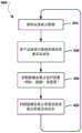
Fig. 3 illustrates an embodiment method 300 for controlling a pulse oximeter based on a patient activity state indicated by accelerometer readings. In one embodiment, the operations of method 300 may be performed by a processor of an electronic patch including a pulse oximeter and an accelerometer (e.g., patch 106 described above). In block 302, a processor may receive accelerometer data from an accelerometer connected to the processor. The accelerometer data may be sampled acceleration measurements provided by the accelerometer or an interrupt received from the accelerometer indicating that an acceleration event (e.g., a peak acceleration event) meeting or exceeding a threshold was detected by the accelerometer. When the accelerometer data is a sampled acceleration measurement provided by an accelerometer, the processor may analyze the acceleration measurement and make a determination based on the received acceleration data. When the accelerometer data is an interrupt signaled by the accelerometer, the processor may analyze the signaled interrupt and make a determination based on the type of interrupt received. In block 304, the processor may determine a patient activity state based on the received accelerometer data. For example, the processor may determine whether the active state of the patient is at rest or active based on the received accelerometer data (e.g., when the accelerometer data is an acceleration measurement, determine whether the active state of the patient is at rest or active by analyzing the acceleration measurement, when the accelerometer data is an interrupt, determine whether the interrupt signals an acceleration level associated with the at rest or active state, etc.). The resting state and/or the active state may be determined based on the received acceleration measurements (e.g., acceleration data and/or interrupt signals) by comparing the received acceleration measurements to threshold values associated with the resting state and/or the active state. For example, while some acceleration may be indicated for the patient (e.g., the patient may not be completely stationary), the acceleration level may be below the threshold value for the rest state, and the active state of the patient may still be determined as the rest state.
In determination block 306, the processor may determine whether the activity state of the patient indicates a rest state. In response to determining that the active state of the patient is not indicated as a rest state (i.e., determining that block 306 is no), the processor may continue to receive accelerometer data in block 302. In this way, the pulse oximeter may not be activated when the patient is active, thereby reducing the chance of erroneous measurements of the pulse oximeter and reducing the consumption of power, since the pulse oximeter may not be activated when the measurements may be erroneous.
In response to determining that the patient activity status does indicate a rest status (i.e., determining that block 306 is "yes"), the processor may turn on the pulse oximeter in block 307. In this way, the pulse oximeter may remain off and draw current only from the power source (e.g., a button cell) when the patient activity state is indicated as the rest state based on the accelerometer data. In block 308, the processor may control the pulse oximeter to make measurements, such as pulse rate measurements, blood oxygen measurements, and the like. In this way, the pulse oximeter may only be activated when the patient is at rest, and the pulse oximeter measurements are more likely to be accurate, thereby saving power by limiting pulse oximeter activity. In block 309, the processor may turn off the pulse oximeter and perform the operations of method 300 in a round-robin fashion by receiving another accelerometer data block 302. In this way, once a pulse oximeter measurement is taken, the pulse oximeter may be turned off to save power.
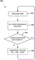
Fig. 4 illustrates an embodiment method 400 for indicating the accuracy of a pulse oximeter reading based on accelerometer readings. In one embodiment, the operations of method 400 may be performed by a processor of an electronic patch including a pulse oximeter and an accelerometer (e.g., patch 106 described above). As described above, in block 302, the processor may receive accelerometer data, and in block 304, the processor may determine a patient activity state based on the received accelerometer data. As described above, in block 308, the processor may control the pulse oximeter to make measurements, such as pulse rate measurements, oximetry measurements, and the like.
In block 402, the processor may indicate a patient activity status using pulse oximeter measurements. For example, the determined patient activity state (e.g., rest or activity state) may be associated with a pulse oximeter measurement (e.g., a measurement database) in memory. Upon indicating the patient activity status with the pulse oximeter measurements, the processor may repeat the method 400 cyclically by returning to performing the operations in block 302.
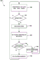
Fig. 5 illustrates an embodiment method 500 for changing a pulse oximeter measurement rate based on a patient activity state indicated by an accelerometer reading. In one embodiment, the operations of method 500 may be performed by a processor of an electronic patch including a pulse oximeter and an accelerometer (e.g., patch 106 described above). In block 502, the processor may control the pulse oximeter to make measurements at a measurement rate, such as pulse rate measurements, oximetry measurements, and the like. For example, the measurement rate may be a variable value indicated in memory (e.g., a sampling rate, such as a measurement per minute), and the processor may periodically activate the pulse oximeter based on the measurement rate. As described above, in block 302, the processor may receive accelerometer data, and in block 304, the processor may determine a patient activity state based on the received accelerometer data.
As described above, in determination block 306, the processor may determine whether the patient activity state is a rest state. In response to determining that the patient activity state is not the rest state (i.e., determining that block 306 is no), the processor may set the measurement rate to a default level in block 504. For example, the default level may be a relatively high measurement rate, such as a high sampling rate. In this way, a higher relative sampling rate may be used to more frequently activate the pulse oximeter when the patient is not at rest. The processor may return to performing the operations in block 502 to control the pulse oximeter at the measurement rate of the default level.
In response to determining that the patient is in a resting state (i.e., determining that block 306 is "yes"), the processor may set the measurement rate to a resting level in block 506. For example, the rest level may be a relatively low measurement rate, such as a low sampling rate. In this way, the pulse oximeter may take fewer samples when the patient is at rest, saving battery power. The processor may return to performing the operations in block 502 to control the pulse oximeter at the measurement rate of the rest state level.
Fig. 6 illustrates an embodiment method 600 for aligning pulse oximeter readings with a patient activity state based on accelerometer readings. In one embodiment, the operations of method 600 may be performed by a processor of an electronic patch (e.g., patch 106 described above) that includes a pulse oximeter and an accelerometer. As described above, in block 302, the processor may receive accelerometer data, and in block 304, the processor may determine a patient activity state based on the received accelerometer data.
In determination block 602, the processor may determine whether the patient activity state satisfies the pulse oximeter measurement conditions. In one embodiment, the patient activity status may be related to instructions to make a pulse oximeter measurement. As an example, a patient entering a rest state may be associated with performing a pulse oximeter measurement, a patient entering a high activity state may be associated with performing a pulse oximeter measurement, and/or a patient reaching a maximum or peak activity rate may be associated with performing a pulse oximeter measurement. In response to determining that the patient activity state does not satisfy the pulse oximeter measurement conditions (i.e., determination block 602 no), the processor may perform the operations in block 302, as described above. In response to determining that the patient activity state satisfies the pulse oximeter measurement conditions (i.e., determining that block 602 is yes), the processor may control the pulse oximeter to take the measurements in block 308, as described above.
Fig. 7 illustrates an embodiment method 700 for correlating heart rate increases with patient status. In an embodiment, the operations of method 700 may be performed by a processor of an electronic patch including a pulse oximeter and an accelerometer (e.g., patch 106 described above). As described above, in block 308, the processor may control the pulse oximeter to make measurements, such as pulse rate measurements, oximetry measurements, and the like. In block 702, the processor may determine whether the pulse rate of the patient has increased. In response to determining that the pulse rate has not increased (i.e., determining block 702 no), the processor may return to performing the operations in block 308.
In response to determining that the pulse rate has increased (i.e., determining that block 702 is "yes"), the processor may receive accelerometer data in block 302, as described above, and determine a patient activity state based on the received accelerometer data in block 304.
In determination block 704, the processor may determine whether the activity state of the patient indicates a state of activity. In response to determining that the patient activity state is not an active state (i.e., determining that block 704 is "no"), the processor may indicate in block 706 that the pulse rate increase is due to pressure and return to controlling the pulse oximeter in block 308. In response to determining that the patient is in an active state (i.e., determining that block 704 is "yes"), the processor may indicate that the pulse rate increase was caused by patient activity in block 708 and return to controlling the pulse oximeter in block 308.
Fig. 8 illustrates an embodiment method 800 for controlling a pulse oximeter based on a patient activity state indicated by accelerometer readings. In one embodiment, the operations of method 800 may be performed by a processor of an electronic patch including a pulse oximeter and an accelerometer (e.g., patch 106 described above). In block 802, the processor may be powered on. For example, the electronic patch may be removed from the packaging and applied to the patient, causing the processor of the electronic patch to be powered on.
In block 804, the processor may reset and start a measurement period countdown timer. The measurement period countdown timer may be a countdown timer monitored by the processor that may be set to a minimum time to wait between performing pulse oximeter measurements. The minimum time to wait between performing pulse oximeter measurements may be set to any time value, e.g., less than 30 minutes, greater than 30 minutes, etc., and may vary based on patient medical conditions or any other factors.
In determination block 806, the processor may determine whether the measurement period countdown timer has expired. In response to determining that the measurement period countdown timer has not expired (i.e., determination block 806 is yes), the processor may continue to monitor the state of the measurement period countdown timer and continue to determine whether the measurement period countdown timer has expired in determination block 806.
In response to determining that the measurement period countdown timer has expired (i.e., determining that block 806 is yes), the processor may reset and start the measurement window countdown timer in block 808. The measurement window countdown timer may be a countdown timer monitored by the processor that may be set to wait for a maximum time for the patient to enter a rest state to perform a pulse oximeter measurement. The measurement window countdown timer may provide a maximum wait time for attempting more accurate pulse oximeter measurements during the patient's rest state. After the measurement window countdown timer expires, the processor may default to making a pulse oximeter measurement regardless of the current patient activity status. In this manner, regardless of the patient activity state, the total time period equal to the measurement period countdown timer plus the measurement window countdown timer may not be exceeded without making a pulse oximeter measurement reading. The maximum wait time for attempting a more accurate pulse oximeter measurement during a patient's rest state may be set to any time value, e.g., less than 10 minutes, greater than 10 minutes, etc., and may vary based on patient medical conditions or any other factor. After the waiting time, the processor will by default take a pulse oximeter measurement regardless of the current patient activity state.
In blocks 302 and 304, the processor may perform the operations of like numbered blocks in the method 300 described above with reference to fig. 3 to receive accelerometer data and determine a patient activity state. In determination block 808, the processor may determine whether the measurement window countdown timer has expired. In response to determining that the measurement window countdown timer has not expired (i.e., determination block 808 ═ no), the processor may determine in determination block 306 whether the patient activity state indicates a rest state, as described above with reference to fig. 3.
In response to determining that the patient is not in the rest state (i.e., determining that block 306 is "no"), the processor may again receive accelerometer data in block 302 and determine a patient activity state in block 304.
In response to determining that the patient is in a rest state (i.e., determining that block 306 is "yes"), or in response to determining that the measurement window countdown timer has expired (i.e., determining that block 808 is "yes"), the processor may turn on the pulse oximeter in block 307, take the measurement in block 308, and turn off the pulse oximeter in block 309, as described with reference to fig. 3. In this way, the pulse oximeter may be activated to take measurements when the patient activity state is a rest state, or a maximum wait time is exceeded regardless of the patient activity state, thereby conserving battery life by only turning on the pulse oximeter to take measurements when the measurements may be accurate or when it is necessary to turn on the pulse oximeter so as not to miss the measurement window. In block 402, the processor may indicate a patient activity state using pulse oximeter measurements, as described with reference to fig. 4. The processor may cyclically perform method 800 by resetting and starting a measurement period countdown timer in block 804. In this way, the pulse oximeter may only be turned on periodically to take measurements and thereby save battery life.
An embodiment patch may be configured to transmit data to any of a variety of computing devices. For example, fig. 9 illustrates a computing device 900 suitable for use in various embodiments. Computing device 900 may exchange data from the electronic patches described above and may perform one or more of the operations of methods 300, 400, 500, 600, 700, and/or 800 described above. For example, accelerometer and/or pulse oximeter measurements may be sent to computing device 900, and pulse oximeter control signals may be sent from computing device 900 to the electronic patch.
In various embodiments, computing device 900 may include a couplingTo the touch screen controller 804 and the internal memory 902. The processor 901 may be one or more multi-core ICs designated for general or specific processing tasks. The internal memory 902 may be volatile or non-volatile memory, and may also be secure and/or encrypted memory, or unsecure and/or unencrypted memory, or any combination thereof. The touchscreen controller 904 and the processor 901 may also be coupled to a touchscreen panel 912, such as a resistive-sensing touchscreen, a capacitive-sensing touchscreen, an infrared-sensing touchscreen, and so forth. Computing device 900 can have one or more wireless signal transceivers 908 coupled to each other and/or to processor 901 (e.g.,Wi-Fi, RF, cellular, etc.) and an antenna 910 for transmitting and receiving. The transceiver 908 and antenna 910 may be used with the above-described circuitry to implement various wireless transmission protocol stacks and interfaces. The computing device 900 may include a cellular network wireless modem chip 916 that enables communication via a cellular network (e.g., an eMBMS network) and is coupled to the processor. Computing device 900 may include a peripheral connection interface 918 coupled to processor 901. Peripheral device connection interface 918 may be configured solely to accept one type of connection or configured to accept various types of physical and communicative connections, whether public or proprietary, such as USB, FireWire, Thunderbolt, or PCIe. Peripheral device connection interface 918 may also be coupled to a similarly configured peripheral device connection port (not shown). Computing device 900 may also include speakers 914 for providing audio output. Computing device 900 may also include a housing 920 constructed of plastic, metal, or a combination of materials for housing all or some of the components discussed herein. Computing device 900 may include a power supply 922 coupled to processor 901, such as a disposable or rechargeable battery. The rechargeable battery may also be coupled to the peripheral device connection port to receive a charging current from a source external to the computing device 900.
The processor of a computing device suitable for use in the various embodiments may be any programmable microprocessor, microcomputer or multiple processor chip or chips that can be configured by software instructions (applications) to perform various functions, including the functions of the various embodiments described above. In various devices, multiple processors may be provided, such as one processor dedicated to wireless communication functions and one processor dedicated to running other applications. Typically, the software may be stored in an internal memory before it is accessed and loaded into the processor. The processor may include internal memory sufficient to store the application software instructions. In many devices, the internal memory may be volatile or non-volatile memory (e.g., flash memory) or a mixture of both. For the purposes of this description, a general reference to memory refers to memory accessible by the processor, including internal or removable memory plugged into the various devices and memory within the processor.
Moreover, those skilled in the art will appreciate that the above method descriptions and process flow diagrams are provided merely as illustrative examples and are not intended to require or imply that the steps of the various embodiments must be performed in the order presented. As will be appreciated by those skilled in the art, the order of the steps in the foregoing embodiments may be performed in any order. Words such as "after," "then," "next," etc. are not intended to limit the order of the steps; these words are used only to guide the reader through the description of the methods. Furthermore, any reference to claim elements in the singular (e.g., using the articles "a," "an," or "said") should not be construed as limiting the element to the singular.
The various illustrative logical blocks, modules, circuits, and algorithm steps described in connection with the embodiments disclosed herein may be implemented as electronic hardware, computer software, or combinations of both. To clearly illustrate this interchangeability of hardware and software, various illustrative components, blocks, modules, circuits, and steps have been described above generally in terms of their functionality. Whether such functionality is implemented as hardware or software depends upon the particular application and design constraints imposed on the overall system. Skilled artisans may implement the described functionality in varying ways for each particular application, but such implementation decisions should not be interpreted as causing a departure from the scope of the embodiments.
The hardware used to implement the various exemplary logic units, logic blocks, modules, and circuits described in connection with the embodiments disclosed herein may be implemented or performed with a general purpose processor, a Digital Signal Processor (DSP), an Application Specific Integrated Circuit (ASIC), a Field Programmable Gate Array (FPGA) or other programmable logic device, discrete gate or transistor logic, discrete hardware components, or any combination thereof designed to perform the functions described herein. A general-purpose processor may be a microprocessor, but in the alternative, the processor may be any conventional processor, controller, microcontroller, or state machine. A processor may also be implemented as a combination of computing devices, e.g., a combination of a DSP and a microprocessor, a plurality of microprocessors, one or more microprocessors in conjunction with a DSP core, or any other such configuration. Alternatively, some steps or methods may be performed by circuitry that is specific to a given function.
The functions in the various embodiments may be implemented in hardware, software, firmware, or any combination thereof. If implemented in software, the functions may be stored as one or more processor-executable instructions or code on a non-transitory computer-readable medium or a non-transitory processor-readable medium. The steps of a method or algorithm disclosed herein may be embodied in processor-executable software modules that may reside on non-transitory computer-readable or processor-readable storage media. A non-transitory computer-readable or processor-readable storage medium may be any storage medium that is accessible by a computer or a processor. By way of example, and not limitation, such non-transitory computer-readable or processor-readable media can comprise RAM, ROM, EEPROM, flash memory, CD-ROM or other optical disk storage, magnetic disk storage or other magnetic storage devices, or any other medium that can be used to store desired program code in the form of instructions or data structures and that can be accessed by a computer. Disk and disc, as used herein, includes Compact Disc (CD), laser disc, optical disc, Digital Versatile Disc (DVD), floppy disk and blu-ray disc where disks usually reproduce data magnetically, while discs reproduce data optically with lasers. Combinations of the above are also included within the scope of non-transitory computer-readable and processor-readable media. Additionally, the operations of a method or algorithm may reside as one or any combination or set of codes and/or instructions on a non-transitory processor-readable medium and/or computer-readable medium, which may be incorporated into a computer program product.
The previous description of the disclosed embodiments is provided to enable any person skilled in the art to make or use the present invention. Various modifications to these embodiments will be readily apparent to those skilled in the art, and the generic principles defined herein may be applied to other embodiments without departing from the spirit or scope of the invention. Thus, the present invention is not intended to be limited to the embodiments shown herein but is to be accorded the widest scope consistent with the following claims and the principles and novel features disclosed herein.