CN106660083B - Anti-fouling system using energy derived from brine - Google Patents
Anti-fouling system using energy derived from brine Download PDFInfo
- Publication number
- CN106660083B CN106660083B CN201580036156.8A CN201580036156A CN106660083B CN 106660083 B CN106660083 B CN 106660083B CN 201580036156 A CN201580036156 A CN 201580036156A CN 106660083 B CN106660083 B CN 106660083B
- Authority
- CN
- China
- Prior art keywords
- fouling
- light
- electrode
- optical medium
- lighting
- Prior art date
- Legal status (The legal status is an assumption and is not a legal conclusion. Google has not performed a legal analysis and makes no representation as to the accuracy of the status listed.)
- Active
Links
- 230000003373 anti-fouling effect Effects 0.000 title claims abstract description 252
- 239000012267 brine Substances 0.000 title description 3
- HPALAKNZSZLMCH-UHFFFAOYSA-M sodium;chloride;hydrate Chemical compound O.[Na+].[Cl-] HPALAKNZSZLMCH-UHFFFAOYSA-M 0.000 title description 3
- 239000007788 liquid Substances 0.000 claims abstract description 77
- 238000003306 harvesting Methods 0.000 claims abstract description 12
- 230000003287 optical effect Effects 0.000 claims description 182
- 238000000034 method Methods 0.000 claims description 35
- 229910000831 Steel Inorganic materials 0.000 claims description 24
- 239000010959 steel Substances 0.000 claims description 24
- 239000013535 sea water Substances 0.000 claims description 15
- HCHKCACWOHOZIP-UHFFFAOYSA-N Zinc Chemical compound [Zn] HCHKCACWOHOZIP-UHFFFAOYSA-N 0.000 claims description 9
- 229910052725 zinc Inorganic materials 0.000 claims description 9
- 239000011701 zinc Substances 0.000 claims description 9
- 239000013307 optical fiber Substances 0.000 claims description 6
- FYYHWMGAXLPEAU-UHFFFAOYSA-N Magnesium Chemical compound [Mg] FYYHWMGAXLPEAU-UHFFFAOYSA-N 0.000 claims description 5
- 238000004210 cathodic protection Methods 0.000 claims description 5
- 239000003623 enhancer Substances 0.000 claims description 5
- 229910052749 magnesium Inorganic materials 0.000 claims description 5
- 239000011777 magnesium Substances 0.000 claims description 5
- 238000005286 illumination Methods 0.000 abstract description 17
- 239000000463 material Substances 0.000 description 76
- XLYOFNOQVPJJNP-UHFFFAOYSA-N water Substances O XLYOFNOQVPJJNP-UHFFFAOYSA-N 0.000 description 41
- 229920001296 polysiloxane Polymers 0.000 description 38
- VYPSYNLAJGMNEJ-UHFFFAOYSA-N silicon dioxide Inorganic materials O=[Si]=O VYPSYNLAJGMNEJ-UHFFFAOYSA-N 0.000 description 34
- 239000010410 layer Substances 0.000 description 26
- 239000011888 foil Substances 0.000 description 19
- 210000004027 cell Anatomy 0.000 description 14
- 244000005700 microbiome Species 0.000 description 14
- 239000000243 solution Substances 0.000 description 13
- 239000000377 silicon dioxide Substances 0.000 description 12
- 238000000576 coating method Methods 0.000 description 11
- 239000007789 gas Substances 0.000 description 11
- 230000008901 benefit Effects 0.000 description 10
- -1 polytetrafluoroethylene Polymers 0.000 description 10
- 230000000694 effects Effects 0.000 description 9
- 229910052751 metal Inorganic materials 0.000 description 9
- 239000002184 metal Substances 0.000 description 9
- 239000002245 particle Substances 0.000 description 8
- 239000000126 substance Substances 0.000 description 8
- 230000032258 transport Effects 0.000 description 8
- 238000009826 distribution Methods 0.000 description 7
- 230000002070 germicidal effect Effects 0.000 description 7
- 230000002829 reductive effect Effects 0.000 description 7
- 230000005540 biological transmission Effects 0.000 description 6
- 239000011248 coating agent Substances 0.000 description 6
- 239000000203 mixture Substances 0.000 description 6
- 230000005855 radiation Effects 0.000 description 6
- 239000007787 solid Substances 0.000 description 6
- 241000251468 Actinopterygii Species 0.000 description 5
- 241000282412 Homo Species 0.000 description 5
- 238000010521 absorption reaction Methods 0.000 description 5
- 238000010168 coupling process Methods 0.000 description 5
- 238000005859 coupling reaction Methods 0.000 description 5
- 238000003892 spreading Methods 0.000 description 5
- 230000007480 spreading Effects 0.000 description 5
- 206010015150 Erythema Diseases 0.000 description 4
- 238000006243 chemical reaction Methods 0.000 description 4
- 239000000446 fuel Substances 0.000 description 4
- 229910052782 aluminium Inorganic materials 0.000 description 3
- XAGFODPZIPBFFR-UHFFFAOYSA-N aluminium Chemical compound [Al] XAGFODPZIPBFFR-UHFFFAOYSA-N 0.000 description 3
- 230000008859 change Effects 0.000 description 3
- 230000001276 controlling effect Effects 0.000 description 3
- 238000005260 corrosion Methods 0.000 description 3
- 230000007797 corrosion Effects 0.000 description 3
- 231100000321 erythema Toxicity 0.000 description 3
- 239000011521 glass Substances 0.000 description 3
- 229920000728 polyester Polymers 0.000 description 3
- 239000004926 polymethyl methacrylate Substances 0.000 description 3
- 239000004800 polyvinyl chloride Substances 0.000 description 3
- 230000009467 reduction Effects 0.000 description 3
- 235000012239 silicon dioxide Nutrition 0.000 description 3
- 241000894007 species Species 0.000 description 3
- 238000011282 treatment Methods 0.000 description 3
- 241001474374 Blennius Species 0.000 description 2
- OKTJSMMVPCPJKN-UHFFFAOYSA-N Carbon Chemical compound [C] OKTJSMMVPCPJKN-UHFFFAOYSA-N 0.000 description 2
- 229910001018 Cast iron Inorganic materials 0.000 description 2
- 241000238586 Cirripedia Species 0.000 description 2
- 206010010741 Conjunctivitis Diseases 0.000 description 2
- 241000195493 Cryptophyta Species 0.000 description 2
- 229920000089 Cyclic olefin copolymer Polymers 0.000 description 2
- 239000004713 Cyclic olefin copolymer Substances 0.000 description 2
- 241001465754 Metazoa Species 0.000 description 2
- CBENFWSGALASAD-UHFFFAOYSA-N Ozone Chemical compound [O-][O+]=O CBENFWSGALASAD-UHFFFAOYSA-N 0.000 description 2
- 229920005372 Plexiglas® Polymers 0.000 description 2
- 229920002319 Poly(methyl acrylate) Polymers 0.000 description 2
- 239000004698 Polyethylene Substances 0.000 description 2
- 239000004743 Polypropylene Substances 0.000 description 2
- XUIMIQQOPSSXEZ-UHFFFAOYSA-N Silicon Chemical compound [Si] XUIMIQQOPSSXEZ-UHFFFAOYSA-N 0.000 description 2
- 238000001720 action spectrum Methods 0.000 description 2
- 230000004071 biological effect Effects 0.000 description 2
- 239000012620 biological material Substances 0.000 description 2
- 230000015572 biosynthetic process Effects 0.000 description 2
- 229920006217 cellulose acetate butyrate Polymers 0.000 description 2
- 238000004140 cleaning Methods 0.000 description 2
- 230000008878 coupling Effects 0.000 description 2
- 239000004205 dimethyl polysiloxane Substances 0.000 description 2
- 229920001971 elastomer Polymers 0.000 description 2
- 238000005516 engineering process Methods 0.000 description 2
- 239000000835 fiber Substances 0.000 description 2
- 230000010354 integration Effects 0.000 description 2
- 150000002500 ions Chemical class 0.000 description 2
- 230000001788 irregular Effects 0.000 description 2
- 238000002955 isolation Methods 0.000 description 2
- 230000000670 limiting effect Effects 0.000 description 2
- 230000000873 masking effect Effects 0.000 description 2
- 150000002739 metals Chemical class 0.000 description 2
- 125000002496 methyl group Chemical group [H]C([H])([H])* 0.000 description 2
- 230000000813 microbial effect Effects 0.000 description 2
- 230000036961 partial effect Effects 0.000 description 2
- 125000001997 phenyl group Chemical group [H]C1=C([H])C([H])=C(*)C([H])=C1[H] 0.000 description 2
- BASFCYQUMIYNBI-UHFFFAOYSA-N platinum Chemical compound [Pt] BASFCYQUMIYNBI-UHFFFAOYSA-N 0.000 description 2
- 229920000435 poly(dimethylsiloxane) Polymers 0.000 description 2
- 229920003207 poly(ethylene-2,6-naphthalate) Polymers 0.000 description 2
- 239000004417 polycarbonate Substances 0.000 description 2
- 239000011112 polyethylene naphthalate Substances 0.000 description 2
- 229920000139 polyethylene terephthalate Polymers 0.000 description 2
- 239000005020 polyethylene terephthalate Substances 0.000 description 2
- 229920000642 polymer Polymers 0.000 description 2
- 229920001343 polytetrafluoroethylene Polymers 0.000 description 2
- 239000004810 polytetrafluoroethylene Substances 0.000 description 2
- 229920000915 polyvinyl chloride Polymers 0.000 description 2
- 230000008569 process Effects 0.000 description 2
- 239000000047 product Substances 0.000 description 2
- 239000008213 purified water Substances 0.000 description 2
- 238000007789 sealing Methods 0.000 description 2
- 229910052710 silicon Inorganic materials 0.000 description 2
- 239000010703 silicon Substances 0.000 description 2
- 238000005507 spraying Methods 0.000 description 2
- 230000003746 surface roughness Effects 0.000 description 2
- 231100000331 toxic Toxicity 0.000 description 2
- 230000002588 toxic effect Effects 0.000 description 2
- 238000002834 transmittance Methods 0.000 description 2
- 238000011144 upstream manufacturing Methods 0.000 description 2
- 238000001429 visible spectrum Methods 0.000 description 2
- 239000002699 waste material Substances 0.000 description 2
- 229910000838 Al alloy Inorganic materials 0.000 description 1
- 241000251557 Ascidiacea Species 0.000 description 1
- 241000894006 Bacteria Species 0.000 description 1
- 229910001369 Brass Inorganic materials 0.000 description 1
- 229910000906 Bronze Inorganic materials 0.000 description 1
- 241000700670 Bryozoa Species 0.000 description 1
- 241000251730 Chondrichthyes Species 0.000 description 1
- RYGMFSIKBFXOCR-UHFFFAOYSA-N Copper Chemical compound [Cu] RYGMFSIKBFXOCR-UHFFFAOYSA-N 0.000 description 1
- 241001481833 Coryphaena hippurus Species 0.000 description 1
- LCGLNKUTAGEVQW-UHFFFAOYSA-N Dimethyl ether Chemical compound COC LCGLNKUTAGEVQW-UHFFFAOYSA-N 0.000 description 1
- 241000193901 Dreissena polymorpha Species 0.000 description 1
- 241000196324 Embryophyta Species 0.000 description 1
- 241000588724 Escherichia coli Species 0.000 description 1
- 229910000640 Fe alloy Inorganic materials 0.000 description 1
- CWYNVVGOOAEACU-UHFFFAOYSA-N Fe2+ Chemical compound [Fe+2] CWYNVVGOOAEACU-UHFFFAOYSA-N 0.000 description 1
- 241000243320 Hydrozoa Species 0.000 description 1
- 206010061218 Inflammation Diseases 0.000 description 1
- 241000237852 Mollusca Species 0.000 description 1
- 241000243820 Polychaeta Species 0.000 description 1
- 229910007161 Si(CH3)3 Inorganic materials 0.000 description 1
- FAPWRFPIFSIZLT-UHFFFAOYSA-M Sodium chloride Chemical compound [Na+].[Cl-] FAPWRFPIFSIZLT-UHFFFAOYSA-M 0.000 description 1
- 238000005299 abrasion Methods 0.000 description 1
- 230000032912 absorption of UV light Effects 0.000 description 1
- 238000009825 accumulation Methods 0.000 description 1
- 230000009471 action Effects 0.000 description 1
- 238000004026 adhesive bonding Methods 0.000 description 1
- 230000002411 adverse Effects 0.000 description 1
- 210000004712 air sac Anatomy 0.000 description 1
- 229910045601 alloy Inorganic materials 0.000 description 1
- 239000000956 alloy Substances 0.000 description 1
- QVGXLLKOCUKJST-UHFFFAOYSA-N atomic oxygen Chemical compound [O] QVGXLLKOCUKJST-UHFFFAOYSA-N 0.000 description 1
- 230000010065 bacterial adhesion Effects 0.000 description 1
- 230000001580 bacterial effect Effects 0.000 description 1
- 238000005452 bending Methods 0.000 description 1
- 239000004443 bio-dispersant Substances 0.000 description 1
- 239000003139 biocide Substances 0.000 description 1
- 230000032770 biofilm formation Effects 0.000 description 1
- 239000010951 brass Substances 0.000 description 1
- 239000010974 bronze Substances 0.000 description 1
- 230000009172 bursting Effects 0.000 description 1
- 239000003990 capacitor Substances 0.000 description 1
- 239000002775 capsule Substances 0.000 description 1
- 229910052799 carbon Inorganic materials 0.000 description 1
- 210000002421 cell wall Anatomy 0.000 description 1
- 239000000919 ceramic Substances 0.000 description 1
- 239000003795 chemical substances by application Substances 0.000 description 1
- 239000000571 coke Substances 0.000 description 1
- 239000002131 composite material Substances 0.000 description 1
- 230000006835 compression Effects 0.000 description 1
- 238000007906 compression Methods 0.000 description 1
- 239000004020 conductor Substances 0.000 description 1
- 230000021615 conjugation Effects 0.000 description 1
- 238000011109 contamination Methods 0.000 description 1
- 229910052802 copper Inorganic materials 0.000 description 1
- 239000010949 copper Substances 0.000 description 1
- KUNSUQLRTQLHQQ-UHFFFAOYSA-N copper tin Chemical compound [Cu].[Sn] KUNSUQLRTQLHQQ-UHFFFAOYSA-N 0.000 description 1
- 230000001419 dependent effect Effects 0.000 description 1
- 238000010612 desalination reaction Methods 0.000 description 1
- 239000006185 dispersion Substances 0.000 description 1
- 238000005553 drilling Methods 0.000 description 1
- 230000002500 effect on skin Effects 0.000 description 1
- 238000004146 energy storage Methods 0.000 description 1
- 239000011152 fibreglass Substances 0.000 description 1
- 239000012467 final product Substances 0.000 description 1
- 239000005357 flat glass Substances 0.000 description 1
- 239000012634 fragment Substances 0.000 description 1
- 239000005350 fused silica glass Substances 0.000 description 1
- 239000003292 glue Substances 0.000 description 1
- 229910002804 graphite Inorganic materials 0.000 description 1
- 239000010439 graphite Substances 0.000 description 1
- 238000005087 graphitization Methods 0.000 description 1
- JEGUKCSWCFPDGT-UHFFFAOYSA-N h2o hydrate Chemical compound O.O JEGUKCSWCFPDGT-UHFFFAOYSA-N 0.000 description 1
- 238000010438 heat treatment Methods 0.000 description 1
- 229920002681 hypalon Polymers 0.000 description 1
- 238000007654 immersion Methods 0.000 description 1
- 230000004054 inflammatory process Effects 0.000 description 1
- 238000003780 insertion Methods 0.000 description 1
- 230000037431 insertion Effects 0.000 description 1
- 230000001678 irradiating effect Effects 0.000 description 1
- 239000011133 lead Substances 0.000 description 1
- 230000031700 light absorption Effects 0.000 description 1
- 238000012423 maintenance Methods 0.000 description 1
- 230000014759 maintenance of location Effects 0.000 description 1
- 238000004519 manufacturing process Methods 0.000 description 1
- QSHDDOUJBYECFT-UHFFFAOYSA-N mercury Chemical compound [Hg] QSHDDOUJBYECFT-UHFFFAOYSA-N 0.000 description 1
- 239000007769 metal material Substances 0.000 description 1
- 239000010445 mica Substances 0.000 description 1
- 229910052618 mica group Inorganic materials 0.000 description 1
- 230000003278 mimic effect Effects 0.000 description 1
- 210000004400 mucous membrane Anatomy 0.000 description 1
- 239000008239 natural water Substances 0.000 description 1
- 230000000422 nocturnal effect Effects 0.000 description 1
- 231100000252 nontoxic Toxicity 0.000 description 1
- 230000003000 nontoxic effect Effects 0.000 description 1
- 239000003921 oil Substances 0.000 description 1
- 239000011368 organic material Substances 0.000 description 1
- 239000001301 oxygen Substances 0.000 description 1
- 229910052760 oxygen Inorganic materials 0.000 description 1
- 239000003973 paint Substances 0.000 description 1
- 238000010422 painting Methods 0.000 description 1
- 239000000575 pesticide Substances 0.000 description 1
- 239000004038 photonic crystal Substances 0.000 description 1
- 229910052697 platinum Inorganic materials 0.000 description 1
- 231100000614 poison Toxicity 0.000 description 1
- 229920003229 poly(methyl methacrylate) Polymers 0.000 description 1
- 229920000515 polycarbonate Polymers 0.000 description 1
- 229920000573 polyethylene Polymers 0.000 description 1
- 229920005644 polyethylene terephthalate glycol copolymer Polymers 0.000 description 1
- 229920001155 polypropylene Polymers 0.000 description 1
- 244000062645 predators Species 0.000 description 1
- 230000000069 prophylactic effect Effects 0.000 description 1
- 239000011253 protective coating Substances 0.000 description 1
- 230000001681 protective effect Effects 0.000 description 1
- 238000003908 quality control method Methods 0.000 description 1
- 239000002096 quantum dot Substances 0.000 description 1
- 239000010453 quartz Substances 0.000 description 1
- 230000001105 regulatory effect Effects 0.000 description 1
- 239000011347 resin Substances 0.000 description 1
- 229920005989 resin Polymers 0.000 description 1
- 150000003839 salts Chemical class 0.000 description 1
- 239000004065 semiconductor Substances 0.000 description 1
- 229920002050 silicone resin Polymers 0.000 description 1
- 229920002379 silicone rubber Polymers 0.000 description 1
- 239000004945 silicone rubber Substances 0.000 description 1
- 239000011780 sodium chloride Substances 0.000 description 1
- 238000005476 soldering Methods 0.000 description 1
- 239000011343 solid material Substances 0.000 description 1
- 125000006850 spacer group Chemical group 0.000 description 1
- 230000003595 spectral effect Effects 0.000 description 1
- 239000000758 substrate Substances 0.000 description 1
- 235000000346 sugar Nutrition 0.000 description 1
- 150000008163 sugars Chemical class 0.000 description 1
- 239000002344 surface layer Substances 0.000 description 1
- 230000001225 therapeutic effect Effects 0.000 description 1
- 239000003440 toxic substance Substances 0.000 description 1
- 238000002211 ultraviolet spectrum Methods 0.000 description 1
- 239000002023 wood Substances 0.000 description 1
Images


Classifications
-
- B—PERFORMING OPERATIONS; TRANSPORTING
- B01—PHYSICAL OR CHEMICAL PROCESSES OR APPARATUS IN GENERAL
- B01J—CHEMICAL OR PHYSICAL PROCESSES, e.g. CATALYSIS OR COLLOID CHEMISTRY; THEIR RELEVANT APPARATUS
- B01J19/00—Chemical, physical or physico-chemical processes in general; Their relevant apparatus
- B01J19/08—Processes employing the direct application of electric or wave energy, or particle radiation; Apparatus therefor
- B01J19/12—Processes employing the direct application of electric or wave energy, or particle radiation; Apparatus therefor employing electromagnetic waves
- B01J19/122—Incoherent waves
- B01J19/123—Ultra-violet light
-
- B—PERFORMING OPERATIONS; TRANSPORTING
- B08—CLEANING
- B08B—CLEANING IN GENERAL; PREVENTION OF FOULING IN GENERAL
- B08B17/00—Methods preventing fouling
- B08B17/02—Preventing deposition of fouling or of dust
-
- B—PERFORMING OPERATIONS; TRANSPORTING
- B63—SHIPS OR OTHER WATERBORNE VESSELS; RELATED EQUIPMENT
- B63B—SHIPS OR OTHER WATERBORNE VESSELS; EQUIPMENT FOR SHIPPING
- B63B59/00—Hull protection specially adapted for vessels; Cleaning devices specially adapted for vessels
- B63B59/04—Preventing hull fouling
-
- B—PERFORMING OPERATIONS; TRANSPORTING
- B63—SHIPS OR OTHER WATERBORNE VESSELS; RELATED EQUIPMENT
- B63B—SHIPS OR OTHER WATERBORNE VESSELS; EQUIPMENT FOR SHIPPING
- B63B59/00—Hull protection specially adapted for vessels; Cleaning devices specially adapted for vessels
- B63B59/06—Cleaning devices for hulls
- B63B59/08—Cleaning devices for hulls of underwater surfaces while afloat
-
- B—PERFORMING OPERATIONS; TRANSPORTING
- B63—SHIPS OR OTHER WATERBORNE VESSELS; RELATED EQUIPMENT
- B63B—SHIPS OR OTHER WATERBORNE VESSELS; EQUIPMENT FOR SHIPPING
- B63B79/00—Monitoring properties or operating parameters of vessels in operation
- B63B79/40—Monitoring properties or operating parameters of vessels in operation for controlling the operation of vessels, e.g. monitoring their speed, routing or maintenance schedules
-
- C—CHEMISTRY; METALLURGY
- C02—TREATMENT OF WATER, WASTE WATER, SEWAGE, OR SLUDGE
- C02F—TREATMENT OF WATER, WASTE WATER, SEWAGE, OR SLUDGE
- C02F1/00—Treatment of water, waste water, or sewage
- C02F1/30—Treatment of water, waste water, or sewage by irradiation
- C02F1/32—Treatment of water, waste water, or sewage by irradiation with ultraviolet light
- C02F1/325—Irradiation devices or lamp constructions
-
- F—MECHANICAL ENGINEERING; LIGHTING; HEATING; WEAPONS; BLASTING
- F21—LIGHTING
- F21V—FUNCTIONAL FEATURES OR DETAILS OF LIGHTING DEVICES OR SYSTEMS THEREOF; STRUCTURAL COMBINATIONS OF LIGHTING DEVICES WITH OTHER ARTICLES, NOT OTHERWISE PROVIDED FOR
- F21V23/00—Arrangement of electric circuit elements in or on lighting devices
- F21V23/003—Arrangement of electric circuit elements in or on lighting devices the elements being electronics drivers or controllers for operating the light source, e.g. for a LED array
-
- F—MECHANICAL ENGINEERING; LIGHTING; HEATING; WEAPONS; BLASTING
- F21—LIGHTING
- F21V—FUNCTIONAL FEATURES OR DETAILS OF LIGHTING DEVICES OR SYSTEMS THEREOF; STRUCTURAL COMBINATIONS OF LIGHTING DEVICES WITH OTHER ARTICLES, NOT OTHERWISE PROVIDED FOR
- F21V9/00—Elements for modifying spectral properties, polarisation or intensity of the light emitted, e.g. filters
- F21V9/40—Elements for modifying spectral properties, polarisation or intensity of the light emitted, e.g. filters with provision for controlling spectral properties, e.g. colour, or intensity
-
- G—PHYSICS
- G02—OPTICS
- G02B—OPTICAL ELEMENTS, SYSTEMS OR APPARATUS
- G02B6/00—Light guides; Structural details of arrangements comprising light guides and other optical elements, e.g. couplings
- G02B6/0001—Light guides; Structural details of arrangements comprising light guides and other optical elements, e.g. couplings specially adapted for lighting devices or systems
- G02B6/0011—Light guides; Structural details of arrangements comprising light guides and other optical elements, e.g. couplings specially adapted for lighting devices or systems the light guides being planar or of plate-like form
- G02B6/0033—Means for improving the coupling-out of light from the light guide
- G02B6/0035—Means for improving the coupling-out of light from the light guide provided on the surface of the light guide or in the bulk of it
- G02B6/004—Scattering dots or dot-like elements, e.g. microbeads, scattering particles, nanoparticles
- G02B6/0043—Scattering dots or dot-like elements, e.g. microbeads, scattering particles, nanoparticles provided on the surface of the light guide
-
- G—PHYSICS
- G02—OPTICS
- G02B—OPTICAL ELEMENTS, SYSTEMS OR APPARATUS
- G02B6/00—Light guides; Structural details of arrangements comprising light guides and other optical elements, e.g. couplings
- G02B6/10—Light guides; Structural details of arrangements comprising light guides and other optical elements, e.g. couplings of the optical waveguide type
- G02B6/102—Light guides; Structural details of arrangements comprising light guides and other optical elements, e.g. couplings of the optical waveguide type for infrared and ultraviolet radiation
-
- B—PERFORMING OPERATIONS; TRANSPORTING
- B63—SHIPS OR OTHER WATERBORNE VESSELS; RELATED EQUIPMENT
- B63B—SHIPS OR OTHER WATERBORNE VESSELS; EQUIPMENT FOR SHIPPING
- B63B2209/00—Energy supply or activating means
- B63B2209/04—Energy supply or activating means water activated batteries
-
- B—PERFORMING OPERATIONS; TRANSPORTING
- B63—SHIPS OR OTHER WATERBORNE VESSELS; RELATED EQUIPMENT
- B63B—SHIPS OR OTHER WATERBORNE VESSELS; EQUIPMENT FOR SHIPPING
- B63B59/00—Hull protection specially adapted for vessels; Cleaning devices specially adapted for vessels
- B63B59/06—Cleaning devices for hulls
-
- C—CHEMISTRY; METALLURGY
- C02—TREATMENT OF WATER, WASTE WATER, SEWAGE, OR SLUDGE
- C02F—TREATMENT OF WATER, WASTE WATER, SEWAGE, OR SLUDGE
- C02F2103/00—Nature of the water, waste water, sewage or sludge to be treated
- C02F2103/08—Seawater, e.g. for desalination
-
- C—CHEMISTRY; METALLURGY
- C02—TREATMENT OF WATER, WASTE WATER, SEWAGE, OR SLUDGE
- C02F—TREATMENT OF WATER, WASTE WATER, SEWAGE, OR SLUDGE
- C02F2201/00—Apparatus for treatment of water, waste water or sewage
- C02F2201/001—Build in apparatus for autonomous on board water supply and wastewater treatment (e.g. for aircrafts, cruiseships, oil drilling platforms, railway trains, space stations)
-
- C—CHEMISTRY; METALLURGY
- C02—TREATMENT OF WATER, WASTE WATER, SEWAGE, OR SLUDGE
- C02F—TREATMENT OF WATER, WASTE WATER, SEWAGE, OR SLUDGE
- C02F2303/00—Specific treatment goals
- C02F2303/20—Prevention of biofouling
-
- F—MECHANICAL ENGINEERING; LIGHTING; HEATING; WEAPONS; BLASTING
- F21—LIGHTING
- F21W—INDEXING SCHEME ASSOCIATED WITH SUBCLASSES F21K, F21L, F21S and F21V, RELATING TO USES OR APPLICATIONS OF LIGHTING DEVICES OR SYSTEMS
- F21W2107/00—Use or application of lighting devices on or in particular types of vehicles
- F21W2107/20—Use or application of lighting devices on or in particular types of vehicles for water vehicles
-
- F—MECHANICAL ENGINEERING; LIGHTING; HEATING; WEAPONS; BLASTING
- F21—LIGHTING
- F21W—INDEXING SCHEME ASSOCIATED WITH SUBCLASSES F21K, F21L, F21S and F21V, RELATING TO USES OR APPLICATIONS OF LIGHTING DEVICES OR SYSTEMS
- F21W2111/00—Use or application of lighting devices or systems for signalling, marking or indicating, not provided for in codes F21W2102/00 – F21W2107/00
- F21W2111/04—Use or application of lighting devices or systems for signalling, marking or indicating, not provided for in codes F21W2102/00 – F21W2107/00 for waterways
-
- F—MECHANICAL ENGINEERING; LIGHTING; HEATING; WEAPONS; BLASTING
- F21—LIGHTING
- F21Y—INDEXING SCHEME ASSOCIATED WITH SUBCLASSES F21K, F21L, F21S and F21V, RELATING TO THE FORM OR THE KIND OF THE LIGHT SOURCES OR OF THE COLOUR OF THE LIGHT EMITTED
- F21Y2115/00—Light-generating elements of semiconductor light sources
- F21Y2115/10—Light-emitting diodes [LED]
-
- Y—GENERAL TAGGING OF NEW TECHNOLOGICAL DEVELOPMENTS; GENERAL TAGGING OF CROSS-SECTIONAL TECHNOLOGIES SPANNING OVER SEVERAL SECTIONS OF THE IPC; TECHNICAL SUBJECTS COVERED BY FORMER USPC CROSS-REFERENCE ART COLLECTIONS [XRACs] AND DIGESTS
- Y02—TECHNOLOGIES OR APPLICATIONS FOR MITIGATION OR ADAPTATION AGAINST CLIMATE CHANGE
- Y02T—CLIMATE CHANGE MITIGATION TECHNOLOGIES RELATED TO TRANSPORTATION
- Y02T70/00—Maritime or waterways transport
Abstract
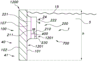
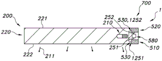
The invention provides an anti-fouling lighting system (1) configured to prevent or reduce biofouling on a fouling surface (1201) of an object (1200) that is at least temporarily exposed to a liquid during use, by providing an anti-fouling light (211) to said fouling surface (1201), the anti-fouling lighting system (1) comprising: a lighting module (200) comprising a light source (210) configured to generate anti-fouling light (211); and an energy system (500) configured to locally harvest energy and to provide power to said light illumination module (200), wherein the energy system (500) comprises (i) a sacrificial electrode (510), and (ii) a second energy system electrode (520), wherein the energy system (500) is configured to provide power to the light illumination module (200) when the sacrificial electrode (510) and the second energy system electrode (520) are in electrical contact with the liquid.
Description
Technical Field
The present invention relates to an anti-fouling lighting system, and to an object, such as a ship or a movable building for use, in particular, in water, comprising such an anti-fouling lighting system. The invention also relates to a method of anti-fouling of a fouling surface (of such an object). Further, the invention relates to a method of providing an anti-fouling lighting system to an object.
Background
Methods of preventing biofouling are known in the art. For example, US2013/0048877 describes a system for preventing biofouling of a protected surface, including an ultraviolet light source configured to generate ultraviolet light; and an optical medium disposed proximate to the protected surface and coupled to receive the ultraviolet light, wherein the optical medium has a thickness direction perpendicular to the protected surface, wherein two orthogonal directions of the optical medium orthogonal to the thickness direction are parallel to the protected surface, wherein the optical medium is configured to provide a propagation path of the ultraviolet light such that the ultraviolet light travels within the optical medium in at least one of the two orthogonal directions orthogonal to the thickness direction, and such that at a plurality of points along a surface of the optical medium, respective portions of the ultraviolet light escape the optical medium.
In WO2007/107722a1, a method of significantly reducing marine fouling is taught that incorporates the use of light in the area around the underwater surface to divert the attention of zooplankton and goblet ascidians. These marine organisms are generally nocturnal to avoid optical predators such as fish. Therefore, they will avoid bright areas. The light may be provided in a fender around the ship or the like, which may direct the light to an area around the underwater surface of the ship. Alternatively, the light may be positioned onto the underwater surface. In addition, the underwater surface can be made reflective to increase the light level around the vessel. In a further alternative, the underwater surface may be coated with a biological or chemiluminescent coating.
In JPS5675290A, protective equipment to prevent organic adhesion is provided around the hull near the waterline. Each of the devices is provided with an ultraviolet ray reflecting member of a curved plate supported by a wire or a vertical rod, and an ultraviolet radiator such as an ultraviolet lamp fixed inside the reflecting member via a holding member containing an electric wire and a transparent cover covering the ultraviolet radiator. Each apparatus is also provided with a base plate integral with the ultraviolet ray reflecting member, and is attached to the hull plate of the ship body via a pad of a permanent magnet, soft rubber, or the like fixed to the base plate. In this configuration, the irradiation of ultraviolet rays near the waterline effectively prevents the adhesion of bacterial slime on the outer surface of the hull.
Disclosure of Invention
Biofouling or biological fouling (also denoted herein as "fouling") is the accumulation of microorganisms, plants, algae, and/or animals on a surface. The variety of bio-fouling organisms is highly diverse and extends far beyond the attachment of barnacles and seaweeds. According to some estimates, over 1700 species, comprising over 4000 organisms, are responsible for biofouling. Biofouling is divided into micro fouling, which includes biofilm formation and bacterial adhesion, and macro fouling, which is the attachment of larger organisms. These organisms are also classified as hard or soft fouling types due to different chemical and biological properties that determine what substances prevent the organisms from fixing. Calcareous (hard) fouling organisms include barnacles, bryozoans, mollusks, polychaetes and other tubworms, and zebra mussels. Examples of non-calcareous (soft) fouling organisms are seaweed, hydroids, algae and biofilm "slime". These organisms together form a fouling community.
In several cases, biofouling creates a number of problems. The machine stops working, the water inlet is blocked and the hull of the vessel is subjected to increased resistance. The subject of anti-fouling, i.e. the process of removing or preventing the formation of fouling, is therefore well known. In industrial processes, biodispersants can be used to control biofouling. In a less controlled environment, organisms are killed or repelled using coatings, heat treatments or energy pulses using biocides. Non-toxic mechanical strategies to prevent biological attachment include selecting materials or coatings with smooth surfaces, or creating nanoscale surface topologies like shark and dolphin skin that provide only poor anchor points. Biofouling on the hull of a ship causes a considerable increase in drag and thus increased fuel consumption. It is estimated that up to a 40% increase in fuel consumption can be attributed to biofouling. Since large oil ships or container transport ships can consume up to &200000a day on fuel, substantial savings are possible by utilizing an effective method of preventing bio fouling.
Therefore, a solution based on optical methods, in particular using ultraviolet light (UV), is proposed. It appears that with sufficient UV light most microorganisms are killed, rendered inactive or unable to reproduce. This effect is mainly controlled by the total dose of UV light. A typical dose that kills 90% of a certain microorganism is 10 milliwatt-hours per square meter, details are contained in the following paragraphs and related figures regarding UV light.
One of the problems/challenges is to provide electrical power to a system that provides (UV) light or anti-fouling light; since this is outside an object, such as a ship with a (very large) hull, the complexity may increase, such as:
drilling holes forming holes for wiring from the generator inside the ship to the systems outside;
-the length of cable extending from the power supply to the actual LED;
any UV LED system will likely have some form of tile to cover up to-10000 m2(or even as much as 40000 for the largest boat circumference). The interconnection between individual tiles can be difficult to make;
both positive and negative electrodes are required, which requires precautions to prevent electrical short circuits, especially in salt water or when damage occurs.
Here we propose to extract the required energy directly from e.g. brine. The combination of saline with two different electrode metals will generate an electric current. This current may power the load. On board a ship, this principle can be intelligently integrated into already existing cathodic protection solutions: an arrangement with two different materials; the steel hull is accompanied by so-called sacrificial anodes, for example made of zinc. Due to the difference in electrochemical potential, the zinc electrode will corrode rapidly; while the steel hull is protected from corrosion. The power generated by this system is not used for any particular purpose; it is simply wasted. Cathodic Protection (CP) is a technique for controlling corrosion of metal surfaces by making the metal surface the cathode of an electrochemical cell. A simple protection method connects the protected metal to the more corrosive "sacrificial metal" which acts as the anode. The sacrificial metal then corrodes, rather than the protected metal. With such a solution, a source of biofouling on the fouling surface (which may especially be a liquid at least temporarily contacting the surface) may also be used as an energy source to prevent and/or reduce biofouling on the fouling surface.
It is therefore an aspect of the present invention to provide an alternative anti-fouling lighting system, and/or an object, such as a vessel, comprising such an anti-fouling lighting system, and/or a movable building for use in water, comprising such an anti-fouling lighting system, and/or an alternative method of anti-fouling of an element (of such a vessel or building, etc.), which additionally preferably at least partly obviates one or more of the above-mentioned disadvantages. It is another aspect of the present invention to provide an alternative method of providing an anti-fouling lighting system to an object, such as a ship, which in addition preferably at least partly obviates one or more of the above-mentioned disadvantages.
In a first aspect, the present invention provides an anti-fouling lighting system ("system" or "lighting system") configured to prevent or reduce bio fouling (electro-conductive aqueous liquid-related, especially electro-conductive water-related, even more especially sea water-related) on a fouling surface of an object, which object is at least temporarily exposed to the electro-conductive aqueous liquid during use, by providing an anti-fouling light to said fouling surface, the anti-fouling lighting system comprising: (a) a lighting module comprising a light source configured to generate anti-fouling light, and (b) an energy system configured to locally harvest energy and configured to provide power to the lighting module. In a particular embodiment, the energy system comprises (i) a sacrificial electrode (in electrical connection with a first electrode of the light source), and (ii) a second energy system electrode (in electrical connection with a second electrode of the light source), wherein the energy system is configured to provide power to the lighting module when the sacrificial electrode and the second energy system electrode are in electrical contact with an electrically conductive aqueous liquid, such as, in particular, seawater. In further embodiments, the energy system may alternatively or additionally further comprise a photovoltaic cell. Additionally, in embodiments, the energy system may include harvesting components such as, for example, embedded solar cells, small turbines operating in water, piezoelectric elements operating on pressure waves, and the like. Such a photovoltaic source or other energy harvesting means may be functionally connected to the first and second electrodes of the light source. The invention is particularly additionally explained in relation to electrochemical cells. The energy system generates electrical power by which electrical current can flow through the electrical circuit and power the light source and/or other (optional) electrical components.
In a further aspect, the invention also provides an object, which during use is at least temporarily exposed to an electrically conductive aqueous liquid (such as seawater), the object comprising a fouling surface, which during use is at least temporarily exposed to an electrically conductive aqueous liquid, the object further comprising an anti-fouling lighting system as defined herein, wherein the lighting module is configured to irradiate at least part of said fouling surface with anti-fouling light. In an embodiment, the object may be a ship comprising a hull. However, the object may also comprise a movable building comprising movable parts, which may for example be a weir, a dam, a sluice, etc., which may have movable parts, such as doors or valves, etc. The mobile building is thus in particular a water mobile building. The movable portion may comprise an element, such as a plate, for example a steel plate. However, other systems than mobile buildings are also included (see also below).
With the present lighting system, the object or at least a part thereof, in particular the fouling surface, may be kept substantially free of biological fouling. Alternatively or additionally, biofouling may be removed efficiently. A substantially autonomous system is provided which does not necessarily require power from within the subject, as the lighting system may draw its own energy. This also allows a single autonomous module (also denoted herein as a "unit") to be provided, which can be easily replaced by a new module. Elements of the object, in particular the sacrificial electrode, can also be replaced if desired. Thus, energy is saved, the object, such as the hull of a ship, is protected, as no via holes are necessary, and fouling may be prevented and/or reduced. In addition, because the energy system is a local source, less wiring may be required. A further possibility is that due to the fact that the energy system is local (as is the case with the electrochemical cell described herein), the light source will only be powered when the energy system, or more particularly the sacrificial electrode and the second energy system electrode, is submerged (in the conducting liquid). This effect can be used to make the lighting unit provide only (UV) light, if necessary, i.e. when the fouling surface is exposed to (sea) water. Thus, the emitting surface of the lighting module and the energy system will typically be at a short distance from each other, such as in the range of 0.1-20m, such as 0.2-10 m.
Herein, the terms "fouling" or "biofouling" or "biological fouling" are used interchangeably. Some examples of fouling are provided above. The described method (see below) and lighting system can be applied to prevent fouling on the hull of a ship, but they can be used for all marine objects, including stationary facilities (pipes, marine stations, etc.) and/or moving marine objects (submarines, etc.). The disclosed anti-fouling solution may also be applied to objects operating in a water course, canal or lake, and may for example also be applied in aquariums and the like. Biofouling may occur on any surface in or near water and temporarily exposed to water (or another electrically conductive aqueous liquid). On such surfaces, biofouling may occur when the element is in or close to water, such as (only) above the horizontal (such as e.g. due to splashing, such as e.g. due to bow waves). Between the regression lines, biofouling can occur within hours. Even at moderate temperatures, the first (staged) fouling will occur within a few hours; just as the first (molecular) level of sugars and bacteria.
The surface or area on which the fouling may be generated is herein denoted as the fouling surface. It may for example be the hull of a ship and/or the emitting surface of an optical medium (see also below). To this end, the lighting module provides an anti-fouling light, which is applied to prevent the formation of and/or remove a bio fouling. This anti-fouling light comprises in particular at least UV radiation (also denoted "UV light"). In particular, the light source comprises a UV LED (see also below) configured to provide one or more of UV-a and UV-C light. UV-A can be used to damage cell walls, while UV-C can be used to damage DNA.
Ultraviolet (UV) is that portion of electromagnetic light that is limited by the lower wavelength limit of the visible spectrum and the X-ray radiation band. The spectral range of UV light is by definition between about 100 and 400nm (1 nm = 10)-9m) and is invisible to the human eye. Using the CIE classification, the UV spectrum is subdivided into three bands: UVA (long wave) from 315 to 400 nm; UVB (medium wave) from 280 to 315 nm; and UVC (short wave) from 100 to 280 nm. In reality, many photobiologists often speak skin effects resulting from UV exposure as weighted effects at wavelengths around 320nm, thus providing an alternative definition.
Light in the short wave UVC band provides a strong germicidal effect. In addition, erythema (redness of the skin) and conjunctivitis (inflammation of the mucous membranes of the eye) can also be caused by this form of light. Because of this, when using germicidal UV-lamps, it is important to design the system to exclude UVC leakage and thus avoid these effects. In the case of an immersion light source, the absorption of UV light by water may be sufficiently strong that UVC leakage is not a problem for people above the liquid surface. Thus, in an embodiment, the anti-fouling light comprises UV-C light.
Self-evidently, humans should avoid exposure to UVC. Fortunately, this is relatively straightforward as it is absorbed by most products, and even standard flat glass absorbs substantially all of the UVC. For example quartz and PTFE (polytetrafluoroethylene) are exceptions. Again, for good luck, UVC is mostly absorbed by the dead skin, and thus erythema can be limited. In addition, UVC does not penetrate the lens of the eye; however, conjunctivitis can occur and, although temporarily, it is extremely painful; the same is true for erythema.
Care should be taken not to exceed the threshold level specification where exposure to UVC light occurs. For practical purposes, Table 1 givesUV thresholds for human exposure over time for the American College of Government Industry Hygienists (ACGIH) limit the effective irradiance values. At this point, it is worth noting that radiation wavelengths below 240nm form ozone O from oxygen in air3. Ozone is toxic and highly reactive; precautions must be taken to avoid exposure to humans and certain materials.
Table 1: permissible UVC exposure to humans according to ACGIH
| Length of daily exposure | Irradiance (μ W/cm)2) |
| 8 hours | 0.2 |
| 4 hours | 0.4 |
| 2 hours | 0.8 |
| 1 hour | 1.7 |
| 30 minutes | 3.3 |
| 15 minutes | 6.6 |
| 10 minutes | 10 |
| 5 |
20 |
| 1 |
100 |
The above listed doses of the germicidal agents can also be easily achieved using existing low cost, low power UV LEDs. LEDs can generally be included in relatively small packages and consume less power than other types of light sources. LEDs can be manufactured to emit (UV) light at various desired wavelengths and their operating parameters can be controlled to a high degree, most notably the output power. Thus, especially the light source is a light source emitting during operation at least light at a wavelength selected from the UV wavelength range (light source light), especially at least UV-C emitting light source. In a particular embodiment, the light source comprises a solid state LED light source (such as an LED or laser diode). The term "light source" may also relate to a plurality of light sources, such as 2-20 (solid state) LED light sources, although a large number of more light sources may also be applied. Thus, the term LED may also refer to a plurality of LEDs. The LEDs may be OLEDs or solid state LEDs, or a combination of these LEDs. In particular, the light source comprises a solid state LED.
In an embodiment, a substantial part of the protected surface to be kept free from fouling, preferably the entire protected surface, for example the hull of a ship, may be covered with a layer emitting germicidal light ("anti-fouling light"), in particular UV light.
In yet another embodiment, the anti-fouling light may be provided to the surface to be protected via an optical fiber or waveguide. Thus, in an embodiment, the anti-fouling lighting system comprises an optical medium, wherein the optical medium comprises one or more of a waveguide and an optical fiber configured to provide said anti-fouling light to the fouling surface. The surface of the optical fiber or waveguide from which the anti-fouling light escapes is also denoted herein as the emitting surface. Generally, this portion of the fiber or waveguide may be at least temporarily submerged. As the anti-fouling light escapes from the emission surface, elements of the object that are at least temporarily exposed to liquid (such as seawater) during use may be irradiated and thereby prevented from fouling. However, the emission surface itself may also be protected against fouling. This effect is used in embodiments of the lighting module comprising the optical medium described below.
An anti-fouling lighting module for protected surfaces comprises at least one light source for generating anti-fouling light and optionally an optical medium for distributing the anti-fouling light from the light source. The at least one light source and/or the optical medium may be arranged at least partially within, on and/or near the protected surface so as to emit anti-fouling light in a direction away from the protected surface. The lighting module is adapted to emit an anti-fouling light, preferably when the protected surface is at least partially submerged in a liquid environment. In an embodiment, the optical medium is a light guide comprising a silicone material or a UV grade silica material. Thus, in a specific embodiment, the lighting module further comprises an optical medium configured to receive at least part of the anti-fouling light and configured to distribute at least part of the anti-fouling light through the optical medium, the optical medium comprising (i) a first medium face, and (i) an emitting surface configured to emit at least part of the distributed anti-fouling light in a direction away from the first medium face of the optical medium. In such embodiments, the fouling surface may comprise the emission surface. Alternatively or additionally, however, the anti-fouling light is (also) used for irradiating the surface of the object. Thus, in such an example, the fouling surface may comprise the surface (of an element) of an object such as a ship's hull. In a particular embodiment, the light source is embedded in an optical medium, and the optical medium contains a transport line for electrical connection with the light source. The term "transport line" may also refer to a plurality of transport lines. For example, in particular, the anti-fouling lighting system, the anti-fouling lighting unit or the entire anti-fouling lighting system may have a flake shape. This may allow for easy application on the surface of (an element of) an object.
The phrase "wherein the sacrificial electrode is electrically connected to a first electrode of the light source, and (ii) the second energy system electrode is electrically connected to a second electrode of the light source" and similar phrases do not imply that there is always a closed circuit with the light source turned on. As noted above, the illumination module may provide the anti-fouling light in pulses, and its intensity may be varied. In addition, (the intensity of) the anti-fouling light may depend on other (predefined parameters). For example, a timer (which may also be powered by the energy system) may be used to switch the anti-fouling light on and off. At least during the anti-fouling light generation, there will be a closed circuit that generates a current that flows through the anti-fouling light source(s). Thus, the phrase "by providing anti-fouling light to the fouling surface" and similar phrases also include embodiments in which anti-fouling light is provided to the fouling surface at least temporarily. As noted above, the present invention allows for intelligent integration of components. This also allows easy application to objects such as ships and the like, as well as easy replacement of objects. Thus, the fact that the energy system provides power to the lighting module allows the lighting module to provide (at least temporarily) the anti-fouling light. The energy system may also provide power to other electrical components, which are not necessarily encompassed by the lighting module.
The anti-fouling lighting module for a protected surface may also be provided as a foil applied to the protected surface, the foil comprising at least one light source for generating anti-fouling light, and a sheet-like optical medium for distributing the anti-fouling light throughout the foil. In an embodiment, the foil has a thickness in the order of several millimeters to several centimeters, such as 0.1-5cm, for example 0.2-2 cm. In an embodiment the foil is substantially unlimited in any direction perpendicular to the thickness direction in order to provide a significantly large foil having dimensions in the order of tens or hundreds of square meters. The foil may be significantly dimensionally constrained in two orthogonal directions perpendicular to the foil thickness direction so as to provide an anti-fouling tile; in another embodiment the foil is significantly size limited in only one direction perpendicular to the direction of foil thickness, so as to provide an elongated strip of anti-fouling foil. Thus, the optical medium and even the lighting module may be provided as tiles or as strips.
Whether arranged in, on and/or near the protected surface, or whether provided as a separate foil or not, the lighting module comprises an emission surface for emitting anti-fouling light from the optical medium into the environment and an application surface opposite to the emission surface for applying or arranging the lighting module to the protected surface. In a preferred embodiment, the emitting surface of the light module is substantially flat in order to avoid pits and grooves that can be the origin of fouling, and in order to avoid bumps to limit the amount of resistance caused by the structure when applied to a protected surface. An advantage of a substantially flat surface over a surface comprising grooves and protrusions or having a significant surface roughness is that it will be more difficult for micro-organisms to adhere to the substantially flat surface than on a rough surface or in pits comprised in said surface, especially in combination with a drag effect in a liquid environment. The term "substantially flat" emission surface refers herein to a surface that masks or shields the thickness of wiring connections and light sources embedded in or attached to the lighting module. The term "substantially planar" may also refer to masking or masking some of the structural unevenness of the protected surface, thereby even improving the drag properties of the protected surface in a liquid environment. Examples of protected surface structural unevenness are welds, rivets, etc. The term "substantially flat" may be quantified as resulting in a variation of the average thickness of the light module of less than 25%, preferably less than 10%. "substantially flat" thus does not necessarily require surface roughness of the machined surface finish.
In a preferred embodiment, the lighting module comprises a two-dimensional grid of light sources for generating the anti-fouling light, and the optical medium is arranged to distribute at least part of the anti-fouling light from the two-dimensional grid of light sources throughout the optical medium, so as to provide a two-dimensional distribution of the anti-fouling light exiting the light module light emitting surface. The two-dimensional grid of light sources may be arranged in a wire mesh structure, a closely-packed structure, a row/column structure, or any other suitable regular or irregular structure. The physical distance between adjacent light sources in the grid may be fixed throughout the grid or may vary, for example, as a function of the light output power required to provide the anti-fouling effect, or as a function of the position of the lighting module on the protected surface (e.g. on the hull of a ship). Advantages of providing a two-dimensional grid light source include that anti-fouling light can be generated close to the area to be protected with anti-fouling light illumination, and that it reduces losses in the optical medium or in the light guide and increases the uniformity of the light distribution. Preferably, the anti-fouling light is distributed generally uniformly throughout the emission surface; this reduces or even prevents under-illuminated areas where fouling would otherwise occur, while at the same time reducing or preventing the waste of energy caused by over-illuminating other areas with more light than is required for anti-fouling.
In a preferred embodiment, the light source is a UV LED. The at least one UV LED or the grid of UV LEDs may be sealed in a liquid-tight package. In an embodiment, the at least one UV LED or the grid of UV LEDs may be embedded in the optical medium. A plurality of UV LEDs may be organized in a grid and electrically connected in a wire mesh structure in series/parallel (as will be explained later). The LEDs and wire mesh connections can be encapsulated in a light transmissive coating and attached to or directly embedded in the optical medium. In other embodiments, the grid of UV LEDs may be contained in an e-woven layer embedded in a resin structure.
In some embodiments, the UV LED may be a packaged LED, in which case the packaged LED may already include optical elements to distribute the light emitted from the LED package across a wide emission angle. In other embodiments, the UV LEDs may be LED dies that typically do not contain optical elements but are significantly thinner than packaged LEDs. As an example, the LED dies may be picked up and placed on the surface of the optical medium (preferably the application surface, although the emission surface would be equally possible, since the small size of the components would hardly interfere with the light emission function of said surface), electrically wired via printed conductive glue, and finally the LED dies and the wiring may be encapsulated with a thin layer/coating of the optical medium or any other back layer for applying the lighting module to the protected surface. Various embodiments of embedded light sources allow the anti-fouling technology provided to be commercialized as foil for application on ship hulls.
A system for anti-fouling of a protected surface may comprise a plurality of lighting modules disclosed herein for arrangement on the protected surface so as to provide anti-fouling light over substantially the entire extent of the protected surface.
The silicone material may provide optical transmission for UV light with less loss compared to other materials. This is especially true for shorter wavelength light, such as UV light with wavelengths below 300 nm. A particularly efficient group of the silicone material is, or at least comprises, the so-called polymethylsilicones (according to the general chemical formula: CH, as customary in organic chemistry)3[Si(CH3)2O]nSi(CH3)3Where "n" represents any suitable integer). This type of silicone material happens to exhibit excellent UV transmission properties, at least with very low losses compared to other silicone materials. In addition, silicone materials are flexible and resilient, so that they are strong, durable and can withstand compression, such as due to impact, collision, etc. of an object with a surface, for example a ship with a bank. Instead of methyl groups, phenyl groups or phenyl and methyl groups may also be present in the silicone resin.
In addition, the deformation of the ship's outer skin due to temperature fluctuations, wave impacts, bending of the ship due to expansion and heave, etc. can be regulated. In addition, silicone materials may be applied and formed on the surface structure: welds, rivets, etc. in or on the surface. Silicone materials also tend to adhere well to metals and paints, allowing protective coatings to form on surfaces. The visible transparent silicone material enables reading of the underlying indicia (e.g., the drawn symbol) covered by the silicone material. In addition, they are generally waterproof and can reduce friction and drag. On the one hand, the silicone can be made very smooth to reduce biofouling organisms to adhere to the layer and reduce friction against flowing water, while on the other hand, the material can be finely structured so as to mimic sharkskin, which is also known to reduce friction in water at a sufficiently fast speed with respect to the surrounding water. It is noted that the optical medium, in particular the structured surface of the light guide, may cause conditions that break total internal reflection and then cause light to be coupled out of the light guide, which light would otherwise be trapped within the light guide and transmitted by means of total internal reflection. Thus, the light outcoupling may be reliably positioned.
UV grade silica has very little absorption for UV light and is therefore well suited as optical media and light guide material. Relatively large objects can be made by using a plurality of relatively small pieces or portions of UV grade silica and/or so-called "fused silica" together, while also maintaining UV transmission properties for larger objects. The silica portion embedded in the silicone material protects the silica material. In such a combination, the silica portion may provide UV transparent scatterers in the further silicone material optical medium for (re) distributing light through the optical medium and/or for facilitating light outcoupling from the light guide. Additionally, the silicone material may be reinforced with silica particles and/or particles of other hard, UV translucent materials. In particular, it is possible to use silica particles in the form of flakes, also at high densities of up to 50%, 70% or even higher percentage of silica in the silicone material, which provides a strong layer that can block impacts. It is contemplated that at least a portion of the optical medium or light guide may provide UV grade silica particles, particularly chips, having a spatial variation in density, which are at least partially embedded in the silicone material, for example to change optical and/or structural properties. By "debris" is herein meant an object having dimensions in three cartesian directions, wherein two of the three dimensions may be different from each other, however each of the two is significantly larger than the third dimension, e.g. 10, 20 or significantly more times, e.g. 100 times the third dimension.
In an embodiment, in a portion of the optical medium proximate to an emission surface for emitting anti-fouling light from the optical medium, the density of UV-grade silica particles in the silicone material may increase from inside the optical medium to the emission surface of the optical medium, such that a relatively high density of silica particles is provided at or near the emission surface. Although more or less spherical and/or randomly shaped particles may be used, sub-millimeter length scale silicon dioxide chips (e.g., typical sizes as low as a few microns) may be placed very close together so that under the influence of very localized forces (such as point impacts from sharp pointed objects, and/or localized impacts from blunt objects, including scratches, cracks, etc.), the chips may have some (if not only a small) freedom of movement in the flexible silicone so that they may rearrange themselves slightly, thereby dissipating the impact energy and reducing damage to the light guide as a whole. Thus, a balance of properties may be maintained, which results in a layer that is both strong and somewhat deformable, but which also provides the desired optical performance. In an embodiment, the proportion of silicone material in the optical medium gradually changes from about 100% (i.e., substantially pure silicone material) to less than about 5% (mostly silicon dioxide) from one side of the optical medium to the opposite side.
Note that particles of other materials than silica (e.g., glass or mica), particularly platelet-shaped particles, may be used. Such other materials may also act as scatterers of anti-fouling light. It is also possible to provide a mixture of particles of different materials, which may comprise a mixture of translucent, opaque and/or optically active particles. The composition of these mixtures may vary throughout the light guide, for example to adjust the transmittance of the light guide for anti-fouling light, particularly if relatively large amounts of transmissive undesirable particles are used in some sections.
To fabricate the optical media, a series of layers of silicone material may be formed, each layer possibly having a different composition with respect to the number and/or density of silica particles. The layers may be very thin and at least some may be applied using wet-on-wet (wet on wet) techniques, i.e. a silicone material is provided to a layer in liquid or gel form which should be hardened to the desired layer, but wherein a subsequent layer is applied to a preceding layer before it is fully hardened. Thus, good adhesion between the layers is promoted and in the final product the different layers may be hardly distinguishable and a gradual change of composition may be achieved. The different layers are suitably formed and/or applied by spraying of layer material. The layered material may be formed to any suitable thickness with high quality control. Note that the optical medium making up a substantial portion of the lighting module surface may be attached to the protected surface in any suitable manner, including adhesion. Silicone materials tend to exhibit strong adhesion to ceramic, glass and metal materials, and spraying or painting silicone materials is therefore a very suitable way to form and attach optical media to substrates. The sprayed and/or painted optical medium can also be easily manufactured in different desired shapes, for example according to the waterline, specific markings and/or surface shapes. The layering technique may also facilitate orienting the particles in the silicone material, e.g., arranging the fragments parallel to the direction of extension of the layer and the surface coated with the layer.
In another aspect of the lighting module, the optical medium comprises a space, e.g. a channel filled with a gas and/or a clear liquid, e.g. water, for guiding light through the channel, and the associated method comprises distributing at least part of the light through such space in the optical medium. It has been found that the optical transmission of UV light through gaseous substances, in particular air, is generally significantly better than the transmission of light through solid materials which, even if considered translucent or transparent by some people, exhibit absorption losses of up to a few percent per millimeter. A clear liquid provides less scattering than a liquid filled space with gas, may transmit UV light well and may also provide structural robustness of the cavity in the optical medium. It has been found that water (most notably clear water) has a relatively high and suitable UV transmittance. Contamination and/or UV absorption may also and/or additionally be reduced if distilled, deionized, and/or otherwise purified water is used. It is therefore considered particularly advantageous to transmit light through the space filled with gas and/or liquid.
In order to distribute the light everywhere on the protected surface, the space filled with gas and/or liquid should preferably be well defined and the channels may be provided in the optical medium. Light that ultimately strikes the channel walls can enter the optical medium and be emitted from the optical medium in a direction away from the protected surface, as well as into the liquid environment to provide anti-fouling light. An optical medium in which an air channel is defined and which is itself well transparent to anti-fouling light additionally ensures that if the optical medium were to leak and liquid medium enters the optical medium, the anti-fouling light generated would still be properly transmitted through the optical medium. The channels may comprise varying diameters. Defining and enclosing wall portions of individual volumes that are (much) larger in size and/or thickness than the corresponding wall portions, e.g. similar to packaged products sold under the brand name "Bubble Wrap", provides a partial channel portion or pocket
In particular embodiments, such gas-containing optical media comprise a silicone material that defines channels and/or other spaces filled with gas and/or liquid; the silicone material can be well shaped to define complex structures. Further advantages of silicone materials with or without additional objects such as silica particles have been stated above.
In an embodiment, the channels and/or other spaces are provided by forming two opposing layers of silicone material that are held apart at a desired distance, the wall portions and/or pillars of silicone material creating a distance, such as an air gap between the layers. Such wall portions and/or pillars may act as scattering centers for (re) distributing light through (channels in) the optical medium and/or for guiding light from the gas and/or liquid filled space(s) into the silicone material. This promotes local emission of light from the optical medium into the liquid environment in which the anti-fouling light is to be put into use.
At least part of the anti-fouling light emitted by the one or more light sources may propagate in a direction having a component substantially parallel to the protected surface, or substantially parallel to the application surface of the foil (when the light module is provided as a foil). This facilitates distributing the light over a significant distance along the application surface of the protected surface or foil, which helps to obtain a suitable intensity distribution of the anti-fouling light.
The wavelength converting material may be contained in the optical medium, and at least part of the anti-fouling light may be generated by photo-exciting the wavelength converting material with light having a first wavelength to cause the wavelength converting material to emit anti-fouling light of another wavelength. The wavelength converting material may be provided as: up-conversion phosphors, quantum dots, nonlinear media such as one or more photonic crystal fibers, and the like. Since light that is different from (primarily longer than) the wavelength of the UV light tends to absorb and/or scatter losses in the optical medium less significantly, it may be more energy efficient to generate non-UV light and transmit the light through the optical medium, and to generate UV anti-fouling light at or near the intended use location of the UV anti-fouling light (i.e., emitted from the surface into the liquid environment). Suitable anti-fouling light is in the UV wavelength range, or alternatively also blue light, from about 220nm to about 420nm, especially shorter wavelengths than about 300nm, for example from about 240nm to about 280 nm.
When applying a wavelength converting material, the phrase "light source configured to generate anti-fouling light" may be interpreted as a light source for generating anti-fouling light in combination with the wavelength converting material. The anti-fouling light is provided either by the light source itself, or by a wavelength converting material that converts the light source light into wavelength converting material light, or by both.
In an embodiment, the optical medium comprises a light spreader arranged in front of the at least one light source for generating anti-fouling light for spreading at least part of the anti-fouling light emitted by the at least one light source in a direction having a component substantially parallel to the protected surface. An example of a light spreader may be an "inverted" cone disposed in the optical medium and located opposite the at least one light source, wherein the inverted cone has a surface area perpendicular to the protected surface at a 45 ° angle for reflecting light emitted by the light source perpendicular to the surface in a direction substantially parallel to the surface. In an embodiment, the optical medium comprises a light guide arranged in front of at least one light source for generating anti-fouling light, the light guide having a light in-coupling surface for coupling in the anti-fouling light from the at least one light source and a light out-coupling surface for coupling out the anti-fouling light in a direction away from the protected surface; the light guide comprises a light guiding material having a refractive index higher than the refractive index of the liquid environment such that at least part of the anti-fouling light propagates through the light guide via total internal reflection in a direction substantially parallel to the protected surface before being coupled out by the coupling-out surface. Some embodiments will comprise an optical medium that combines a light spreader and a light guide, or integrates light spreading features and light guiding features into the optical medium. In embodiments, the light spreader and/or light guide is coated onto the protected surface. In other embodiments, the light spreader and/or light guide is provided in the form factor of a foil for application to a protected surface.
Embodiments of a system for preventing fouling may comprise:
-a series of UV LEDs for generating anti-fouling light;
-a light spreader for spreading anti-fouling light from the LED point light sources throughout the protected surface; and
a light guide (or waveguide) for further guiding/spreading the anti-fouling light, possibly spread throughout the surface, comprising a thin layer of silicone material transparent to UV light, with or without silica particles or one or more silica-covered portions.
When substantially the entire protected surface is covered with the anti-fouling light-emitting optical medium, microbial growth on this medium is significantly reduced. Because the microorganisms are killed on the emitting surface of the optical medium, the hull is continuously cleaned by the water flowing along the hull, which transports debris away from the vessel, and there is no opportunity for microorganisms to become lodged on the hull.
The advantage of the currently provided solution is that the microorganisms are not killed after having adhered or rooted to the surface of the fouling, as is the case with the known toxic dispersion coatings, but the rooting of the microorganisms on the surface of the fouling is prevented. It is more efficient to actively kill microorganisms just before or just after they contact the surface of the fouling than light treatment to remove existing fouling with large microbial structures. This effect would be similar to that produced using a nano-surface that is so smooth that microorganisms cannot adhere to it.
Since a small amount of light energy is required to kill the microorganisms in the initial rooting stage, the system can be operated to provide anti-fouling light continuously throughout a large surface without requiring extreme power requirements.
The LED grid creating the illuminated surface may be provided with energy harvesting components such as, for example, embedded solar cells, small turbines operating in water, piezoelectric elements operating on pressure waves, etc.
Some advantages of the currently provided technology include retention time of clean surfaces, reduction of corrosion treatment costs, reduction of ship fuel consumption, reduction of hull maintenance time, CO2Reduced emissions, reduced use of toxic substances in the environment, and the like. The substantially flat and smooth light emission surface also has the following advantages: it does not increase resistance by itself and can even further reduce resistance by burying existing unevenness (rivets, welds, etc.) of the protected surface under the optical medium.
The object (see also below) may comprise one or more elements which are at least temporarily exposed to the liquid. Such an element may comprise a first element surface, which may be at least temporarily exposed to a liquid. Such an element may also comprise a second element surface, which may be directed towards the body of the object.
Instead of or in addition to silicone, as a material of the optical medium, one or more materials selected from the group consisting of transmissive organic materials such as those selected from the group consisting of: PE (polyethylene), PP (polypropylene), PEN (polyethylene naphthalate), PC (polycarbonate), polymethyl acrylate (PMA), polymethyl methacrylate (PPMA) (plexiglas or plexiglas), Cellulose Acetate Butyrate (CAB), polyvinyl chloride (PVC), polyethylene terephthalate (PET), (PETG) (glycolised polyester), PDMS (polydimethylsiloxane), and COC (cyclic olefin copolymer). In particular, optical media are not rigid. For example, the optical medium may be applied to the hull of a ship. However, the optical media may also be constructed on the hull of a ship by applying material to the hull and thereby forming the optical media.
The optical medium is configured to receive at least a portion of the anti-fouling light of the light source. Thus, in particular, the light source and the optical medium are radiationally coupled. The term "radiationally coupled" especially means that the light source and the optical medium are associated with each other such that at least part of the radiation emitted by the light source is received by the optical medium. The optical medium is configured to distribute the anti-fouling light through the optical medium. This can be attributed to the fact that the optical medium has in particular light guiding properties (of the waveguide). Optionally, the light source is embedded in the optical medium (see also below).
In addition, the optical medium may further comprise a outcoupling structure to outcouple the anti-fouling light. Thus, anti-fouling light, which is trapped within the optical medium by total internal reflection, may escape the optical medium due to outcoupling via the outcoupling structures. These outcoupling structures may be embedded in the optical medium and/or may be arranged at the surface of the optical medium. In particular, the out-coupling structure, optionally in combination with a reflector at least part of the first dielectric face, is configured to promote anti-fouling light to be emitted from the emission surface in a direction away from the first dielectric face (i.e. during use of the lighting module: away from the first element surface of the element (see also below)). This light is used to prevent and/or remove biofouling at the emission surface of the light emitting module.
As noted above and below, the illumination module may consist essentially of an optical medium. For example, one or more of the control system and the power supply may (also) be embedded in the optical medium. In addition, since a single LED may provide a large area of anti-fouling light through the optical medium, the surface area of the lighting module may in embodiments be at least 80% composed of the optical medium. Optical media may be used for the sealing element. Thus, the first media face may have a surface area substantially the same as the surface area of the first element surface. In particular, the first media face is in physical contact with the first element surface. Even more particularly, the entire first media face is in physical contact with the first element surface. The phrase "the emission surface is configured to be further from the first element surface than the first medium face" means that the first medium face of the optical medium is closer to the first element surface of the element than the emission surface. In this way, the anti-fouling light can escape in a direction away from the element. As noted above, in some embodiments, at least part of the first dielectric face, or in particular the entire first dielectric face, may be in physical contact with (the first element surface of) the element. The term "seal" and similar terms may particularly denote that a liquid, such as water, especially sea water, is (substantially) unable to reach the portion to be sealed.
More than one lighting module may be applied to an object, such as a single element of such an object. Thus, the term "lighting module" may also refer to a plurality of lighting modules. In addition, a single illumination system may include multiple optical media. Thus, the term "optical medium" may also refer to a plurality of optical media. Of course, the anti-fouling lighting system may also comprise a plurality of elements. Thus, as noted above, the term "element" may also refer to a plurality of lighting elements. The term "element" may for example in one embodiment refer to a plate of a ship hull, such as a steel plate. However, the term "element" may also refer to the entire hull. The term "element" especially refers to a part of the hull at the waterside, especially in case of a marine embodiment.
In an embodiment, a lighting module may comprise the control system and optionally also a power supply. In this way, the system may be provided at the first element surface of the element without having to include vias through the element. This may be advantageous, especially from the point of view of element protection. Additionally, the power source may optionally include a local energy harvesting system described herein, such as a system that generates electrical energy from water, particularly conductive aqueous liquids, such as, particularly, seawater, and/or a photovoltaic system. Both of the above can advantageously be arranged at elements, the former being in particular below (intended) level and the latter being in particular above (intended) level.
Herein, the present invention is described with respect to an electrically conductive liquid. However, the present invention may also be related to a conductive nonaqueous liquid. Such (aqueous or non-aqueous) liquids are especially electrically conductive due to the presence of ions, such as in the case of seawater. Thus, in particular the electrically conductive aqueous liquid comprises seawater.
In an embodiment, the anti-fouling lighting system further comprises a control system. In particular, the control system is configured to control the intensity of the anti-fouling light as a function of one or more of feedback and a timer. The term control system may refer to an electronic circuit, such as a sensor in an electric circuit, which allows or causes another action after a threshold level is reached, such as switching light on or off, and/or may refer to a control unit which may comprise (programmable) software. In an embodiment, the control system comprises a (linear) feedback system. The control system may thus be configured to manipulate the lighting module (in particular its anti-fouling light). The term "controlling the intensity" may refer to the on/off state of the anti-fouling light, but may alternatively or additionally also refer to high and low intensities of the anti-fouling light. It may also refer to a stepwise, stepless increase or decrease of the anti-fouling light between a maximum and a minimum (such as no intensity).
The timer may for example be a system that triggers the lighting module to provide light for a certain period of time and to switch off for another period of time. Thus, in an embodiment, the lighting system is configured to provide the anti-fouling light in a pulsed manner, wherein the time periods with the anti-fouling light alternate with the time periods without the anti-fouling light. The optical pulses may include one or more of block (square) pulses, triangular pulses, sawtooth pulses, unipolar quasi-sinusoidal pulses (such as, for example, with rectification), and so forth. The frequency may be from a few seconds to hours, or even days. Alternatively, the pulsed light may comprise slow and fast pulses, e.g. 3 hours on and 3 hours off, wherein during on the pulsed light is provided at a frequency in the range of 0.001-200Hz, such as 0.01-20 Hz. By using pulsed light, in particular at a relatively low frequency such as < 0.01Hz, biofouling may be formed in the dark period and in the on period, biofouling may be efficiently removed. Thus, less light is wasted. Thus, in a specific embodiment, the anti-fouling lighting system may be configured to provide the anti-fouling light in a pulsed manner, wherein the time periods with the anti-fouling light alternate with the time periods without the anti-fouling light. For this purpose, for example, a combination of a control system and a timer may be applied to provide the anti-fouling light in a pulsed manner.
The lighting system may further comprise a sensor. The term "sensor" may also relate to a plurality of sensors. Typical embodiments of the anti-fouling lighting system may particularly comprise the following:
-sensors for one or more parameters (see below);
-software to calculate the amount of power required based on the parameter values and knowledge of the minimum power setting (e.g. predefined setting) preventing fouling;
-a control unit for adjusting the effective output power; as a whole or as each segment of, for example, a ship hull or another element.
In a particular embodiment, the control system is configured to control the intensity of the anti-fouling light as a function of feedback from the sensor, wherein the sensor is configured to sense one or more of: (i) a speed of a vessel containing the lighting module, (ii) a relative speed of water flow (on the fouling surface side), (iii) a water temperature of water (on the fouling surface side), (iv) a load of the vessel containing the lighting module, (v) a position of the emission surface (on the fouling surface side) relative to a conductive water level of the conductive water liquid. The conductive water level may be especially a horizontal level, even more especially a sea water level.
Some aspects of the system are described above, including integration options. In a further embodiment, the anti-fouling lighting system comprises an integrated unit comprising (i) a lighting module and one or more of: the sacrificial electrode and the second energy system electrode, and optionally one or more of: a control system, (timer) and a sensor, wherein the control system is configured to control the intensity of the anti-fouling light as a function of one or more of: (i) a feedback signal from the sensor relating to the risk of biofouling and (ii) a timer for (periodically) changing the intensity of the antifouling light. In yet another embodiment, the anti-fouling lighting system comprises an integrated unit comprising (i) a lighting module and (a) one or more of a control system, a timer, and a sensor, wherein the control system is configured to control the intensity of the anti-fouling light as a function of one or more of: (i) a feedback signal from a sensor relating to a biofouling risk, and (ii) a timer for (periodically) varying the intensity of the antifouling light, and optionally including (b) one or more of the sacrificial electrode and the second energy system electrode. Such a unit can be conveniently attached to an existing surface of an object to prevent or reduce fouling, and may also take into account existing infrastructure, such as that used for sacrificial electrodes. When included in the integrated unit, the sacrificial electrode is particularly configured to be removable, such as with fastening/releasing members or screws or the like. This allows replacement after extensive use of e.g. a sacrificial electrode.
In addition, when one or more of the sacrificial electrode and said second energy system electrode are integrated into a cell, at least part of these electrodes are accessible from outside the cell. In this way, the liquid can be in contact with the sacrificial electrode and the second energy system electrode such that an electrical circuit can be formed. Thus, although for example all components may be embedded in a silicon optical medium or other optical medium, the sacrificial electrode and/or said second energy system electrode (when also integrated into the cell) are accessible to electrically conductive aqueous liquid (whereas other electrical components will generally not be accessible to this liquid and will be fully embedded in the lighting module, in particular in the optical medium). When both the sacrificial electrode and said second energy system electrode are integrated into a unit, it is not necessary to use the steel of the ship's hull, for example. Thus, the surface of (an element of) the object to be protected may comprise steel, but may optionally also comprise another material such as for example selected from the group consisting of: wood, polyester, composites, aluminum, rubber, chlorosulfonated polyethylene, PVC, fiberglass, and the like. Thus, instead of a steel hull, the hull may also be a PVC hull or a polyester hull, etc. Instead of steel, another ferrous material, such as (other) ferrous alloys, is also possible.
In particular, the integrated unit is a closed unit comprising an emission surface, wherein only one or more of the first electrode of the light source, the second electrode of the light source, the sacrificial electrode and the second energy system electrode may reach the outside (and may be exposed to the liquid).
The integrated unit may for example be a (silicone) foil or a (silicone) tile, which may be applied to the surface of (an element of) the object. All elements may be embedded therein, the second energy system electrode and the sacrificial electrode may be used for contact with a liquid, in particular sea water.
Optionally, the sensor may also be configured to monitor the sacrificial electrode, in particular the control system giving a warning signal after a predetermined value indicative of the sacrificial electrode status.
The light source, in particular the solid-state light source, may comprise a first electrode and a second electrode (see also above). The latter may for example be contact-free. The latter may for example be in contact with the steel hull of a ship or other objects. This may be via the second energy system electrode; for example, a steel hull or other steel surface may function as the second energy system electrode. The former, i.e. the first electrode of the light source, may in particular be in contact with the sacrificial electrode. In addition, the sacrificial electrode and the second energy system electrode may especially be in contact with water containing ions, i.e. an electrically conductive liquid, such as an electrically conductive aqueous liquid, such as especially sea water. In this way, there is a circuit with a potential difference between the sacrificial electrode and the second energy system electrode, and thus a potential difference between the first electrode and the second electrode. Thus, in particular, the sacrificial electrode and the second energy system electrode comprise different materials.
In a particular embodiment, the sacrificial electrode comprises one or more of zinc and magnesium. In further embodiments, the second energy system electrode comprises steel, such as steel. However, instead of or in addition to e.g. steel, other materials may also be applied, such as, inter alia, one or more of carbon, graphite, coke, platinum, scale on steel, high silicon cast iron, copper, brass, bronze, lead and cast iron (without graphitization). The phrase "wherein the sacrificial electrode comprises one or more of zinc and magnesium" may also mean that the sacrificial electrode comprises an alloy comprising zinc and/or magnesium. However, the sacrificial electrode may also consist essentially of zinc and/or magnesium. Other materials, such as certain aluminum or aluminum alloys, may also be used.
In particular, the illumination system, in particular the energy system, may further comprise a voltage difference enhancer configured to increase the voltage difference between the first electrode and the second electrode of the light source. For example, "joule thieves" may be applied. Joule thieves and devices with similar properties, such as boost converters, may be applied to increase the potential difference obtainable with the energy system, which may be somewhat lower for e.g. solid state light sources. In particular, the sacrificial electrode and the second energy system electrode comprise a material that, when in contact with seawater or other conductive liquid, provides a potential difference of at least 0.25V, even more particularly at least 0.35V, between these electrodes. In combination with the voltage difference enhancer, a potential difference between the first electrode and the second electrode may be created, useful for e.g. a (UV) solid state light source. The terms "sacrificial electrode" and "second energy system electrode" may also refer to a plurality of sacrificial electrodes and second energy system electrodes, respectively, independently. The phrase "in electrical contact with the electrically conductive aqueous liquid" especially means that the electrodes are in physical contact with the liquid. Thus, a closed circuit may be formed, which allows the energy system to power the lighting module, in particular the light source. The energy system may also supply power to other (optional) components, such as sensors, control systems, timers, etc. Thus, in an embodiment, one or more of the control system and the sensors (and optionally other electrical components, such as optionally a timer, etc.) are also powered by the energy system. For example, the lighting module may be configured to vary the intensity of the anti-fouling light. To this end, the lighting module may comprise electrical components, such as a control system, to (periodically) vary the anti-fouling light intensity. Therefore, a voltage difference enhancer may be applied to also increase the voltage difference for other electrical components of the lighting system (especially the lighting module, such as the optional control system). Hence, in an embodiment, in the anti-fouling lighting system according to any one of the preceding claims, the anti-fouling lighting system further comprises a voltage difference enhancer configured to increase the voltage difference of the power provided to the lighting modules. The current provided may be lower, but the voltage difference may be sufficient to power the light source and/or other optional electrical components of the lighting system.
As indicated above, the present invention also provides an object (which is at least temporarily exposed to an electrically conductive aqueous liquid, in particular during use), comprising a fouling surface (which is at least temporarily exposed to an electrically conductive aqueous liquid during use), the object further comprising an anti-fouling lighting system as described herein, wherein the lighting module is configured to irradiate (during use of the object) at least part of said anti-fouling surface with anti-fouling light. Irradiation may be accomplished directly with a light source, or, for example, via an optical fiber or via a waveguide (such as the optical media described herein). As noted above, the object may be, for example, a ship, a fish pond, a sluice, a fish cage, other movable or stationary marine object, and the like. In a particular embodiment, the object comprises a marine vessel, wherein the marine vessel comprises a steel hull, and wherein the hull is configured as the second energy system electrode. The fouling surface may be a part of the surface of (an element of) the object and/or may be an emitting surface of the illumination system (in particular an emitting surface of an optical medium, when comprised by the illumination system; see also below). Thus, in an embodiment, the object is selected from the group consisting of a vessel, a weir, a dam, a fish pond, a sluice, a fish cage and a navigation mark.
As noted above, the lighting module may additionally comprise an optical medium configured to receive at least part of the anti-fouling light and configured to distribute at least part of the anti-fouling light through the optical medium, the optical medium comprising: (ia) a first media face, and (ib) an emission surface configured to emit at least part of the distributed anti-fouling light in a direction away from the first media face of the optical media. In particular, the first media face is in physical contact with the first element surface.
In yet a further embodiment, the object comprises a plurality of lighting modules arranged over at least part of the height of the object, wherein the control system is configured to control the intensity of the anti-fouling light as a function of the position of the lighting modules relative to the electrically conductive aqueous liquid level of the electrically conductive aqueous liquid at the side of the fouling surface. In particular, the height of an object is defined as the height of the object from the lowest point below the liquid level to the highest point of the object, used in e.g. water. The height of the elements of such an object is defined by the height defined with respect to the vertical direction from the lowest point to the highest point. For example, the hull height may be the height from the keel to, for example, a railing. Advantageously, unwanted anti-fouling light above the horizontal plane may be reduced (and waste of light and energy may be reduced), whereas below the horizontal plane anti-fouling light may be provided. This also enhances safety (of humans and/or animals), since for example exposure of humans to UV radiation is desired to be as small as possible. Thus, the control system may be configured to control the intensity of the anti-fouling light as a function of the position of the lighting module relative to a depth of the lighting module below the level of the electrically conductive water (on the fouling surface side) of the electrically conductive water liquid.
In yet another further embodiment, the invention also provides an anti-fouling lighting system (configured to prevent or reduce biofouling on a fouling surface of an object that is at least temporarily exposed to an electrically conductive aqueous liquid during use by providing an anti-fouling light to said fouling surface, the anti-fouling lighting system comprising: (a) a lighting module comprising a light source configured to generate anti-fouling light; and (b) an energy system configured to locally harvest energy and to provide power to the light illumination module, wherein the energy system comprises (a) a sacrificial electrode in electrical connection with a first electrode of the light source, and/or a (first) electrical connection for connection with such sacrificial electrode, the (first) electrical connection being in electrical connection with the first electrode of the light source, and (ii) a second energy system electrode in electrical connection with a second electrode of the light source, and/or a (second) electrical connection for connection with such second energy system electrode, the (second) electrical connection being in electrical connection with the second electrode of the light source; wherein the energy system is configured to provide power to the lighting module when the sacrificial electrode and the second energy system electrode are in electrical contact with the conductive aqueous liquid. One or more of the sacrificial electrode and the second energy system electrode may already be available in existing structures. Thus, such an anti-fouling lighting unit may be applied to existing infrastructures already comprising sacrificial electrodes, for example.
In yet another aspect, the present invention also provides a method of preventing fouling of a fouled surface of an object, the object being at least temporarily exposed to an electrically conductive aqueous liquid during use, the method comprising: (a) providing a lighting module as defined herein; (b) generating anti-fouling light, optionally as a function of one or more of: (i) a feedback signal relating to a biofouling risk and (ii) a timer for (periodically) varying the intensity of the antifouling light; and (c) providing the anti-fouling light to the fouling surface. In this way the vessel may be kept clean from biological fouling, or biological fouling may be removed, during use of the object, such as during sailing and/or during stay in port. The same applies to other objects that can be protected against fouling with this method. The phrase "anti-fouling method" means that the fouling is prevented and/or that the fouling can be removed. Thus, the method may be therapeutic and/or prophylactic. The method may in particular additionally comprise controlling the intensity of the anti-fouling light as a function of the sensor feedback, such as in particular defined above. For example, one scenario may contemplate a 3 hour off, 5 minute on schedule. In the examples, the antifouling light is provided for 0.2 to 10 minutes per hour. In a further embodiment, the anti-fouling light is provided for 30-300 minutes every (natural) day, i.e. every 24 hours. The on-time and/or off-time may be variable, for example based on a feedback signal. In particular, the anti-fouling light will be generated when the object is at least partially exposed to the electrically conductive aqueous liquid, as will usually be the case (depending on the intended use of the object) when the object is used. Thus, the anti-fouling lighting system may be configured to provide the anti-fouling light with a variable intensity during use of the anti-fouling lighting system, optionally comprising on and off periods of the anti-fouling light. To this end, the anti-fouling lighting system, in particular the module, may comprise further electrical elements such as a timer and/or a control system.
In a still further aspect, the invention provides a method of providing an anti-fouling lighting system to an object, which object is at least temporarily exposed to an electrically conductive aqueous liquid during use, the method comprising providing a vessel with a lighting module (and an energy system) as defined herein, the lighting module being configured to provide (during use) said anti-fouling light to a fouling surface of one or more of the object and the lighting module attached to the object. Thus, the anti-fouling lighting system (and energy system) may also be applied to existing objects. For example, the anti-fouling lighting system may be integrated into an existing infrastructure for sacrificial electrodes. When the energy system and the lighting module are functionally coupled, the anti-fouling lighting system is provided to the object. With the anti-fouling method and with the method of providing an anti-fouling lighting system to an object, the fouling surface can be protected. As indicated above, the fouling surface may especially comprise one or more of the following: an emitting surface of an optical medium, and a first element surface of an element comprised by a hull of the vessel. Thus, when applying the anti-fouling lighting system to an object, one or more elements of the energy system may already be available at the (existing) object.
The term "substantially" herein, such as "substantially all light" or "substantially consisting of" will be understood by those skilled in the art. The term "substantially" may also include embodiments having "entirely," "completely," "all," and the like. Thus, in embodiments, the adjective "substantially" may also be removed. Where applicable, the term "substantially" may also relate to 90% or more, such as 95% or more, especially 99% or more, even more especially 99.5% or more, including 100%. The term "comprising" also includes embodiments in which the term "comprises" means "consisting of. The term "and/or" especially relates to one or more of the items mentioned before and after "and/or". For example, the phrase "item 1 and/or item 2" and similar phrases may refer to one or more of item 1 and item 2. The term "comprising" may mean "consisting of" in one embodiment, but may also mean "containing at least the defined species and optionally containing one or more other species" in another embodiment.
Furthermore, the terms first, second, third and the like in the description and in the claims, are used for distinguishing between similar elements and not necessarily for describing a sequential or chronological order. It is to be understood that the terms so used are interchangeable under appropriate circumstances and that the embodiments of the invention described herein are capable of operation in other sequences than described or illustrated herein.
The apparatus herein is described, inter alia, during operation. As will be clear to a person skilled in the art, the invention is not limited to the apparatus in operation or the method of operation.
It should be noted that the above-mentioned embodiments illustrate rather than limit the invention, and that those skilled in the art will be able to design many alternative embodiments without departing from the scope of the appended claims. In the claims, any reference signs placed between parentheses shall not be construed as limiting the claim. Use of the verb "comprise" and its conjugations does not exclude the presence of elements or steps other than those stated in a claim. The article "a" or "an" preceding an element does not exclude the presence of a plurality of such elements. The invention can be implemented by means of hardware comprising several distinct elements, and by means of a suitably programmed computer. In a device claim enumerating several means, several of these means may be embodied by one and the same item of hardware. The mere fact that certain measures are recited in mutually different dependent claims does not indicate that a combination of these measures cannot be used to advantage.
The invention is also applicable to devices comprising one or more of the salient features described in the description and/or shown in the drawings. The invention also relates to a method or process comprising one or more of the salient features described in the description and/or shown in the drawings.
The various aspects discussed in this patent may be combined to provide additional advantages. Furthermore, some features may form the basis of one or more divisional applications.
Drawings
Embodiments of the invention will now be described, by way of example only, with reference to the accompanying schematic drawings in which corresponding reference symbols indicate corresponding parts, and in which:
FIG. 1 is a graph showing the germicidal action spectrum for different biological materials as a function of light wavelength;
FIG. 2 is a schematic cross-sectional view of a light module having a light guide;
FIG. 3 shows an embodiment comprising a redistribution reflector and a wavelength converting material;
4a-c show an embodiment of a wire mesh grid;
5a-5d schematically depict certain aspects of the illumination systems described herein;
6a-6c schematically depict some aspects of an anti-fouling lighting system and its applications; and
fig. 7a-7e schematically depict some aspects of an anti-fouling lighting system and its applications.
The drawings are not necessarily to scale.
Detailed Description
While the disclosure has been illustrated and described in detail in the drawings and foregoing description, such illustration and description are to be considered illustrative or exemplary and not restrictive; the present disclosure is not limited to the disclosed embodiments.
FIG. 1 is a graph showing the germicidal action spectra for different biomaterials as a function of wavelength, where RE denotes the relative effect, and Curve 1 denotes the germicidal action from the IES Lighting Handbook, Volume, 1987, pages 14-19; curve 2 represents the light absorption of e.coli (Biological Effects of ultraviolet radiation from w.hart, cambridge university press, 1980) and curve 3 represents the DNA absorption (also from the IES manual).
Fig. 2 shows a cross section of a lighting module 200 as a basic embodiment, comprising a plurality of light sources 210 (here side-emitting LEDs, where light is emitted mainly from the sides of the LED and more or less parallel to the surface) encapsulated within a liquid-tight optical medium 220 guiding at least part of the light 211 emitted from the light sources 210 through the optical medium via total internal reflection, which optical medium is additionally provided with optical structures 7 to scatter the light 211 and to guide the light 211 out of the optical medium 220 towards an object 1200 (a biofouling organism) to be aimed at with the light. The optical medium 220 generally extends significantly more in two dimensions than in the third dimension, such that a two-dimensional-like object is provided. The optical structures 7 that scatter light 211 may be dispersed in one or more portions of the optical media material, possibly throughout the optical media material, where the distribution may be generally uniform or localized in these portions. Scattering centers having different structural properties may be combined to provide structural features, such as abrasion resistance and/or impact resistance, in addition to optical features. Suitable diffusers include opaque objects, although largely translucent objects, such as small bubbles, glass and/or silica; the refractive index change is only required to occur for the wavelength(s) used.
The principles of directing light and spreading light over a surface are well known and widely used in a variety of fields. Herein, this principle is applied to UV light for anti-fouling purposes. Note that the idea of making surfaces such as ship hulls self-lit with UV (self-lit) is a significantly different solution than the current and widely accepted anti-fouling solutions that rely on smooth coatings, chemicals, cleaning, software to control ship speed, etc.
Total internal reflection is one way of transmitting light through an optical medium, which is then often referred to as a light guide. To maintain the conditions for total internal reflection, the refractive index of the light guide should be higher than the refractive index of the surrounding medium. However, the use of a (partially) reflective coating on the light guide and/or the use of reflective properties of a protected surface, e.g. a ship's hull, may itself also be used to establish the conditions for guiding light through the optical medium.
In some embodiments, the optical medium may be positioned relative to a protected surface, such as a ship's hull, such that a small air gap is introduced between the optical medium and the protected surface; UV light may travel even better in air-absorb less than in an optical medium, even when this optical medium is designed as a light-conducting material. In other embodiments, the gas-filled channels, such as air channels, may be formed in a silicone material. An array of individual gas-filled bladders may also be provided, for example, in a regular pattern, such as a rectangular or honeycomb pattern, or in an irregular pattern. Instead of filling with a gas (e.g. air), the channels and/or the capsules may be at least partially filled with a UV-transmissive liquid, e.g. clear water and/or purified water. In the event that a protected surface covered with such an optical medium is subjected to an impact, such as a ship hitting a dock edge, a small bladder may cushion, redistribute the impact energy, and thus protect the surface, wherein a liquid-filled bladder may be stronger when deformed than an air bladder that may be more prone to bursting.
Since most materials have a (very) limited UV light transmission, care must be taken in the design of the optical medium. A number of specific features and/or embodiments specific to this purpose are set forth below:
the relatively small pitch of the low power LEDs can be chosen to minimize the distance light must travel through the optical medium.
A "hollow" structure may be used, for example a silicone rubber pad with spacers that keep it a small distance from the protected surface. This creates an air "channel" through which UV light can propagate with high efficiency (air is very transparent to UV). The use of gas-filled channels provided by this structure allows the distribution of UV light over a great distance in the optical medium, which would otherwise be of a material that would not be useful for anti-fouling because it would absorb UV light too strongly. Similarly, separate bladders may be formed.
Special materials with high UV transparency can be chosen, such as certain silicones or UV-grade (fused) silica. In an embodiment, this special material may be used only to create a channel for light to travel most of the distance; cheaper/stronger materials can be used for the remaining surface.
Further embodiments are disclosed in the figures, where the main problem is to use anti-fouling light, preferably UV light, whereas large surfaces are illuminated using point light sources. A typical concern is to spread the light from a point source to the surface illumination. In more detail:
-protected surface area of typical cargo ship is 10000m2。
Typical LED sources have 1mm2The area of (a). This is smaller than 1010And (4) doubling.
Considering the required power level, about 10 LEDs per square meter may be required.
This means that light must be spread from one LED at 1000cm2Above.
As another critical condition, the solution should be thin (order of magnitude: 1 cm), for example, for reasons such as:
in order to be able to add this solution as a "coating" to the ship
In order not to increase the resistance due to the increase in the cross-sectional dimensions of the vessel
To keep the (bulk) material costs limited.
The use of an optical medium, in particular the use of a substantially flat light guide, is thus provided. Typical dimensions for the light guide are a thickness of about 1mm to about 10 mm. In other directions, from an optical point of view, there are no practical limitations on size; the dimensions are particularly not limited if a plurality of light sources are provided such that the attenuation of the light intensity throughout the light guide due to partial outcoupling of light and possible (absorption) losses is counteracted.
It is considered herein that similar optical challenges apply as with the design of LED television backlights, but the emitted light intensity uniformity is less stringent in anti-fouling than with LED television backlights.
Additional ideas and solutions exist to achieve higher uniformity within thinner optical structures, such as introducing diffusers and/or reflectors or other light spreaders directly in front of one or more light sources.
Fig. 3 (left hand side) shows that a light distributor in the form of a reflection cone 25 is contained in the optical medium 220, with its tip facing the light source 210. This directs the light 211 in a direction having a component substantially parallel to the surface 101 to be protected from fouling. If the cone 25 is not fully reflective nor opaque, some light from the light source will pass through the cone and the creation of shadows resulting in reduced or ineffective anti-fouling is prevented.
In addition, fig. 3 shows the wavelength conversion material CM contained in the optical medium 220. The illustrated embodiment is configured to generate at least part of the anti-fouling light by photo-exciting the wavelength converting material CM with light from the light source 2100, the light 31 having the first wavelength causing the wavelength converting material to emit anti-fouling light 211 of another wavelength from the optical medium 220 into the environment E (i.e., downstream of the emission surface 222). The distribution of the wavelength converting material in the optical medium 220 may for example be spatially varied in accordance with a (desired) intensity distribution of (different wavelengths of) light in the optical medium 220.
The terms "upstream" and "downstream" relate to an arrangement of items or features relative to the propagation of light from the light emitting member (herein especially the first light source), wherein, relative to a first position in the beam of light from the light emitting member, a second position in the beam of light closer to the light emitting member is "upstream" and a third position in the beam of light further away from the light emitting member is "downstream".
Fig. 4a-4c show a wire mesh embodiment in which light sources 210, such as UV LEDs, are arranged in a grid and connected in a series parallel connection. The LEDs can be mounted at the nodes as shown in fig. 4b for connecting the LEDs to the wire 4, either by soldering, or by gluing, or by any other known electrical connection technique. One or more LEDs may be placed at each node. DC or AC driving may be implemented. In the case of DC, the LEDs are mounted as shown in fig. 4 c. If AC is used, then a pair of LEDs in an anti-parallel configuration is used, as shown in FIG. 4 c. Those skilled in the art will appreciate that more than one pair of anti-parallel configured LEDs may be used at each node. The actual size of the wire mesh grid and the distance between the UV LEDs in the grid can be adjusted by stretching the harmonica structure. A wire mesh grid may be embedded in the optical medium, wherein optionally a parallel grid of scattering features is provided as illustrated in fig. 3.
In addition to the anti-fouling application of the hull of the vessel, the following alternative applications and embodiments are envisaged:
the present disclosure can be applied to a wide range of fields. Almost any object that comes into contact with natural water will suffer from biofouling over time. This can obstruct, for example, the water inlet of a desalination plant, plugging the piping of a pump station, or even covering the walls or bottom of an outdoor pool. All these applications would benefit from the currently provided method, lighting module and/or system, i.e. an effective thin additional surface layer, which prevents bio fouling over the whole surface area.
Although UV light is the preferred solution, other wavelengths are also envisaged. non-UV light (visible light) is also effective for biofouling. Typical microorganisms are less sensitive to non-UV light than UV light, however, the per unit input power supplied to the light source can produce much higher doses in the visible spectrum.
UV LEDs are an ideal source for thin light emitting surfaces. However, UV sources other than LEDs may also be used, such as low pressure mercury vapor lamps. The form factor of these light sources is very different; in general, the light source is much larger. This results in different optical designs to "distribute" all the light from a single light source over a large area. Although the concept of light guiding discussed herein is unchanged. In addition, a significant contribution of light of a desired wavelength and/or combination of wavelengths may result.
Instead of using a thin layer emitting UV light outwards in a direction away from the protected surface in order to avoid biofouling, it is also possible to potentially remove biofouling by applying UV light from the outside in the direction of the protected surface. For example, as described, UV light is irradiated onto a hull or surface containing a suitable optical medium. Thus, a single optical medium that emits anti-fouling light in a direction toward and away from the protected surface may be even more efficient.
Fig. 5a-5d schematically depict some embodiments and variations of the anti-fouling system. Fig. 5a schematically depicts an anti-fouling lighting system 1 comprising a lighting module 200 and optionally a control system 300. Here, a vessel 20 with the hull 21 is schematically depicted as an example of an object 1200 with a fouling surface 1201. The fouling surface 1201 may be (part of) a surface of the element 100 and/or an element or system associated with the object 1200. Element 100 represents an element of the object such as, for example, hull 21 of vessel 20. In this schematically depicted embodiment, the object 1200 also comprises an anti-fouling lighting system, comprising an emitting surface (see below). Thus, the fouling surface 1201 may for example also comprise such an emission surface 220.
The element 100 comprises a first element surface 101 and a second face 102, the first element surface 101 comprising, for example, at least 0.4m2The area of (a). For example, the second face 102 may be an inner wall (reference numeral 23 denotes a keel) of the hull 21 of the vessel 20. The first element surface 101 is the face facing (in this embodiment) the outside of the vessel 20, which will at least partly contact the liquid 5, in particular water, during use. The liquid level is indicated by reference numeral 15. As can be seen, at least part of the element 100 is submerged.
The lighting module 200 contains a light source and optionally an optical medium 220. In particular, the light source 210 is configured to generate anti-fouling light 211, which may comprise, inter alia, UV light, even more particularly at least UV-C light. The optical medium 220 is particularly configured to receive at least part of the anti-fouling light 211 and is further configured to distribute at least part of the anti-fouling light 211 through the optical medium 220. The optical medium comprises a first medium side 221 and an emission surface 222, the first medium side 221 may for example have at least 0.4m2Is configured to emit at least part of the distributed anti-fouling light 211 in a direction away from the first medium face 221 of the optical medium 220. Here, the first medium face 221 is directed towards the first element surface 101 of the element 100. In this embodiment, optical medium 220 is in physical contact with first element surface 101 of the optical element. For example, in such embodiments, at least part of the illumination module 200 is thus configured to seal at least part of the first element surface 101, the emission surface 222 being configured to be further from the first element surface 101 than the first medium face 221. In addition, the lighting system 1 comprises a control system 300 configured to control the intensity of the anti-fouling light 211 as a function of one or more of feedback and a timer. Optional timerAre depicted, but may alternatively be integrated into the control system. Alternatively, a sensor, indicated with reference numeral 400, may sense the time signal. Reference numeral 230 denotes a power source, which may draw power locally, or it may be a battery, for example. Alternatively, the power may be provided from the vessel. Reference h denotes the height of the element 100.
By way of example, the power supply 230, the control system 300, and the sensor 400 are all integrated into the lighting module 200 and form a single unit with the optical medium 220. The lighting module 200 may cover substantially the entire element 100. Here, by way of example, only a portion of the first face 101 is covered. In the embodiment depicted in FIG. 5a, a first optical media surface is attached to a first side of element 100. FIG. 5b schematically depicts, by way of example only, an embodiment in which the optical medium is attached to the element 100; thereby creating a cavity 107. Note that at least part of the lighting unit seals the first element surface of element 100. Here, by way of example, the element is a wall or a door or a movable building 40, such as a dam or a sluice. Fig. 5c shows, by way of example, a plurality of elements 100, and also a plurality of lighting modules 200. The lighting system further comprises a plurality of sensors 400, and a single control system 300. Additionally, the local energy harvesting system 230 may be, for example, a photovoltaic cell. The lighting module 200 may in one embodiment form a single integrated unit, and as a whole the sealing element 100. With such a system it is possible to monitor which optical media 220 are below the liquid level 15. As shown in the figure, only those optical media below the liquid level 15 will provide the anti-fouling light 211. Of course, more lighting modules than the schematically depicted lighting module would be available. Fig. 5d schematically depicts a separate illumination system 1, which optionally may also be coupled. For example, the control system 300 may optionally communicate (wirelessly). However, the lighting system may also work independently.
As shown for example in some schematically depicted embodiments, the integrated unit 700 may be in particular a closed unit, the emission surface 221 being one of the faces. In fig. 5a-5d, electrodes etc. are not depicted for the sake of simplicity. However, these will be elucidated further below with reference to fig. 6a-6c and 7a-7 e.
Note that the fouling surface 1201 may in some embodiments (also) comprise an emission surface (222), see in particular fig. 5a-5 b.
Fig. 6a-6c schematically depict some aspects of an anti-fouling lighting system and its applications. For example, one aspect of the invention is the insertion of UV LEDs and/or other light sources 210 in an electrical circuit that may already be available in an object 1200 having a (steel) fouling surface 1201 and a sacrificial electrode 510 attached to the fouling surface, a comparison between the case without a light source 210 (fig. 6 a) and the case with a light source (fig. 6b and 6 c) being seen in fig. 6a-6 c. The dashed lines represent by way of example an electrical circuit through the steel fouling surface 1201. The steel hull 21, here the fouling surface 1201, may act as a second energy source electrode 520. In this way, an energy system 500 is provided that can be used to power the light source 210. Fig. 6b shows the introduction of a light source 210, which may illuminate a fouling surface 1201, and which may be powered by the energy system 500.
Fig. 6c schematically depicts in more detail an embodiment of the anti-fouling lighting system 1 (here also in an embodiment of a closed unit), wherein the light source 210 is comprised by way of example by an optical medium 220. The anti-fouling lighting system is further elucidated with respect to this embodiment in particular, although the invention is not limited to this embodiment. Fig. 6c schematically depicts an anti-fouling lighting system 1 configured to prevent or reduce biofouling (associated with water) on a fouling surface 1201 of an object 1200, which is at least temporarily exposed to an electrically conductive aqueous liquid during use, by providing anti-fouling light 211 to said fouling surface 1201. The anti-fouling lighting system 1 comprises: (a) a lighting module 200 comprising a light source 210 configured to generate anti-fouling light 211; and (b) an energy system 500 configured to locally harvest energy and to provide power to said light illumination module 200, wherein the energy system 500 comprises (i) a sacrificial electrode 510 (which is electrically connected to a first electrode 251 of the light source 210), and (ii) a second energy system electrode 520 (which is electrically connected to a second electrode 252 of the light source 210), wherein the energy system 500 is configured to provide power to the lighting module 200 when the sacrificial electrode 510 and the second energy system electrode 520 are in electrical contact with a conductive aqueous liquid, such as, inter alia, seawater (such as liquid 5). The light source 210 is embedded in the optical medium 220. The optical medium 220 contains transport lines 530 for electrical connection 1251, 1252 to the light sources 210. Here, two transport lines are available. Note that the optical medium may be a polymer, wherein the entire light source may be embedded in the polymer. Note that surface or hull 21 is the surface to be protected (having elements with a protected surface). By arranging the lighting unit 1, in particular the optical medium 220, to a large part of this surface to be protected, the soiled surface is transformed into a surface of the lighting unit 1, in particular the optical medium. Thus, in this embodiment, the anti-fouling light will prevent fouling of the emission surface 221. Thus, the fouling surface 1201 here comprises the emission surface 222 of the optical medium 220. Thus, in this embodiment, the emission surface 222 is actually the surface to be protected.
Fig. 7a-7e schematically depict some aspects of an anti-fouling lighting system and its applications. Fig. 7a and 7b schematically depict some options and aspects of the invention in more detail. In addition, fig. 7a schematically depicts the application of a power booster, such as a "joule thief", denoted with reference numeral 580, to increase the voltage difference between the first electrode 251 and the second electrode 252 of the light source 210. In addition to or instead of such "joule thieves", a boost converter (boost converter) may be applied as a power booster. A boost converter is a DC-to-DC power converter with an output voltage higher than its input voltage. It is a type of Switched Mode Power Supply (SMPS) that contains at least two semiconductors (diodes and transistors) and at least one energy storage element, i.e. a capacitor, an inductor or a combination of both. "Joule thief" is a simple self-oscillating booster that is small in size, low in cost, and easy to build; typically for driving light loads. It can use almost all of the energy in a single cell, even well below the voltage at which other circuits believe the cell is fully discharged (or "drained"). The circuit may use the self-oscillating nature of the intermittent oscillator to form an unregulated boost converter. The output voltage increases at the expense of drawing more current at the input. Alternatively or additionally, a flyback converter may be applied. Flyback converters may be used in DC/DC conversion with galvanic isolation between the input and any output. More precisely, a flyback converter is a buck-boost converter with an inductor forming a transformer separately, so that the voltage ratio is multiplied, with the additional advantage of isolation.
In fig. 7a, the light of the light source 210 is introduced into an optical medium, such as an optical fiber or waveguide, from which (from the emission surface 222) the anti-fouling light can escape, optionally after being distributed over the optical medium. This anti-fouling light, shown at the top of the figure, can be used to anti-foul a fouled surface (not depicted). Fig. 7b schematically depicts an option in which the light source 210 is embedded in an optical medium 220, e.g. a silicone foil or tile. The first electrode 251 and the second electrode 252 may here extend as electrical connections 1251, 1252, respectively, through the optical medium and may be accessible from outside the optical medium 220 via transport lines 530. These electrodes may be connected to corresponding electrodes of the energy system (not depicted; see above; and see fig. 7 e).
Fig. 7c-7d schematically depict some embodiments of the lighting unit 1, wherein several components are provided in the integrated unit 700. The integrated unit 700 may contain the lighting module 200 and one or more of the following: the sacrificial electrode 510 (see fig. 7 c) and the second energy system electrode 520 (see fig. 7 d), and optionally includes one or more of a control system (not depicted), a timer (not depicted), and a sensor (not depicted). Combinations such as those two embodiments comprising the sacrificial electrode 510 and the second energy system electrode 520 are of course also possible. The embodiment of fig. 7c may, for example, be attached to a surface of an object 1200 (not depicted), wherein the surface is, for example, a steel hull. This may also apply to the embodiment of fig. 7d, although this embodiment may already contain a second energy system electrode, but this unit will also be electrically connected to a sacrificial electrode (not shown) via electrical connection 1251.
Thus, while the embodiment of fig. 7d may require an object comprising a sacrificial electrode to electrically connect to the first electrode 251 of the light source, this embodiment does not necessarily require an object having a steel hull or other element that can be used as the second energy system electrode 520, as this electrode is already comprised in the anti-fouling system 1, in particular the cell 700. Accordingly, the type of surface to which this anti-fouling system 1, and in particular the unit 700, may be applied may not be limiting. In contrast, although the embodiment of fig. 7c may require an object comprising the second energy system electrode 520 to be electrically connected to the second electrode 252 of the light source, this embodiment does not necessarily require an object with the sacrificial electrode 510, as this electrode is already comprised in the anti-fouling system 1, in particular in the cell 700. Here, the type of surface to which this anti-fouling system 1, in particular the unit 700, can be applied, can be more restrictive. In order to provide a fully autonomous system that can be applied to prevent fouling or protect any surface, the embodiments of fig. 7c and 7d can be combined, as schematically shown in fig. 7 d. Fig. 7a-7e do not depict other optional components such as those depicted schematically in fig. 5a-5 d. Of course, however, also control systems, sensors, timers and the like may be available and integrated, for example, in the unit 700. Additionally, the energy system 700 may also power such optional electronic components.
Accordingly, the present invention provides an anti-fouling lighting system 1 configured to prevent or reduce biofouling on a fouling surface 1201 of an object 1200, which object is at least temporarily exposed to an electrically conductive aqueous liquid during use, by providing an anti-fouling light 211 to said fouling surface 1201, the anti-fouling lighting system 1 comprising: a lighting module 200 comprising a light source 210 configured to generate anti-fouling light 211; and b an energy system 500 configured to locally harvest energy and configured to provide power to said light illumination module 200, wherein the energy system 500 comprises i a sacrificial electrode 510, and ii a second energy system electrode 520, wherein the energy system 500 is configured to provide power to the light illumination module 200 when the sacrificial electrode 510 and the second energy system electrode 520 are in electrical contact with the conductive aqueous liquid.
Depending on the exact metal used for the anode and the exact LED used, the voltage generated may not be sufficient to directly power the LED. In this case, a simple DC-DC converter can generate a higher voltage. For example, so-called "joule thieves" can operate with voltages as low as 0.35V. The total power required and hence the amount of sacrificial electrode required can be estimated from:
o energy content of about 368 amp-hours per pound of zinc; 1108 amp hours for aluminum; a 3mA current at a voltage of 3V will produce an electrical power of 10mW = optical power of 1mW in the UVC range (@ 1% conversion efficiency)
Biological fouling on an area of 1m2 can be prevented by UVC light of o 1 mW.
o for a large ship (10000 m)2) Therefore 10000 x 3mA =30A is required. This consumes (corrodes) one pound of zinc per 12 hours, or about 360 kg/year. Thus, with a relatively simple system, and by reusing several already existing components on the vessel hull, the UV anti-fouling system can be powered.
Therefore, anti-fouling solutions that release certain chemicals or pesticides currently have a large market share. To be effective, these coatings must provide a harsh environment for the living being. A disadvantage is that over time, either by deliberate release or by inevitable cleaning of the surface, those chemicals are released into the water. These chemicals often remain active and have an adverse effect on the environment. A fundamentally different way of preventing biofouling is by using UV light emission. It is known that UV light is effective to deactivate or even kill microorganisms provided that a sufficient dose of the appropriate wavelength is applied. An example of this is ballast water treatment. We will propose a new solution for preventing biofouling, in which a UV light emitting layer is applied outside the hull of a ship. The introduction of UV-LEDs as light sources enables the realization of thin, coating-like structures in which the UV light is uniformly spread within the surface. Further optical design elements will ensure that the light escapes more or less evenly throughout the coating. The UV emitting layer will reduce the likelihood of, or even prevent, attachment of microorganisms to the hull. In experimental settings, we have achieved satisfactory results in keeping surfaces free from biofouling for extended periods of time. The two elements are arranged in the sea water and left there around. One element was irradiated with UV light; the other was not irradiated with UV light. After four weeks, the former only included fouling where no UV light was received; the location itself is not inherently fouled. The latter element is completely covered by the dirt.
Claims (18)
1. An anti-fouling lighting system (1) configured to prevent or reduce biofouling on a fouling surface (1201) of an object (1200) that is at least temporarily exposed to an electrically conductive aqueous liquid during use, by providing an anti-fouling light (211) to the fouling surface (1201), the anti-fouling lighting system being used in combination with a cathodic protection solution comprising a cathode and a sacrificial electrode forming an anode, the object comprising the cathodic protection solution, wherein the fouling surface is the cathode, the anti-fouling lighting system (1) comprising:
a lighting module (200) comprising a light source (210) configured to generate the anti-fouling light (211); and
an energy system (500) configured to locally harvest energy and to provide power to the lighting module (200), wherein the energy system (500) comprises (i) the sacrificial electrode (510) electrically connected to a first electrode (251) of the light source (210), and (ii) a second energy system electrode (520) electrically connected to a second electrode (252) of the light source (210), wherein the energy system (500) is configured to provide power to the lighting module (200) when the sacrificial electrode (510) and the second energy system electrode (520) are in electrical contact with the electrically conductive aqueous liquid.
2. The anti-fouling lighting system (1) according to claim 1, wherein the light source (210) comprises a UV LED configured to provide UV-a and/or UV-C light.
3. The anti-fouling lighting system (1) according to claim 1 or 2, wherein the sacrificial electrode (510) comprises zinc and/or magnesium, wherein the second energy system electrode (520) comprises steel, and wherein the anti-fouling lighting system (1) further comprises a voltage difference enhancer (580) configured to increase the voltage difference between the first electrode (251) and the second electrode (251) of the light source (210).
4. The anti-fouling lighting system (1) according to claim 1 or 2, wherein the anti-fouling lighting system (1) comprises an optical medium (220), wherein the optical medium (220) comprises a waveguide and/or an optical fiber configured to provide the anti-fouling light to the fouling surface (1201).
5. The anti-fouling lighting system (1) according to claim 1 or 2, wherein the lighting module (200) further comprises an optical medium (220) configured to receive at least part of the anti-fouling light (211) and to distribute at least part of the anti-fouling light (211) through the optical medium (220), the optical medium comprising an emission surface (222) configured to emit at least part of the distributed anti-fouling light (211) in a direction away from the optical medium (220), wherein the fouling surface (1201) comprises the emission surface (222).
6. The anti-fouling lighting system (1) according to claim 5, wherein the light source (210) is embedded in the optical medium (220), and wherein the optical medium (220) comprises a transport line (530) for an electrical connection (1251, 1252) with the light source (210).
7. The anti-fouling lighting system (1) according to claim 1 or 2, wherein the sacrificial electrode (510) and/or the second energy system electrode (520) are comprised in an integrated unit (700) and the lighting module (200) is comprised in the integrated unit (700).
8. The anti-fouling lighting system (1) according to claim 7, wherein the integrated unit further comprises a control system (300), wherein the control system (300) is configured to control the intensity of the anti-fouling light (211) as a function of (i) a feedback signal related to a bio-fouling risk and/or (ii) a timer for varying the intensity of the anti-fouling light (211) over time, and wherein the control system (300) is also powered by the energy system (500).
9. The anti-fouling lighting system (1) according to claim 8, configured to provide the anti-fouling light (211) in a pulsed manner, wherein time periods with the anti-fouling light (211) alternate with time periods without the anti-fouling light (211).
10. The anti-fouling lighting system (1) according to claim 7, wherein the integrated unit further comprises a control system (300) and a sensor (400), wherein the control system (300) is configured to control the intensity of the anti-fouling light (211) as a function of (i) a feedback signal from the sensor (400), the feedback signal relating to a bio-fouling risk, and/or (ii) a timer for varying the intensity of the anti-fouling light (211) over time, and wherein the control system (300) and/or the sensor (400) is also powered by the energy system (500).
11. The anti-fouling lighting system (1) according to claim 10, configured to provide the anti-fouling light (211) in a pulsed manner, wherein time periods with the anti-fouling light (211) alternate with time periods without the anti-fouling light (211).
12. An object (1200) comprising a fouling surface (1201) which is at least temporarily exposed to an electrically conductive aqueous liquid during use, the object (1200) further comprising an anti-fouling lighting system (1) as defined in any one of claims 1-7.
13. An object (1200) comprising a fouling surface (1201) which is at least temporarily exposed to an electrically conductive aqueous liquid during use, the object (1200) further comprising an anti-fouling lighting system (1) as defined in any one of claims 8-11.
14. The object (1200) according to claim 13, comprising a plurality of lighting modules (200), the lighting modules (200) being arranged on the object (1200) along a vertical direction defined by the highest and lowest points of the object, wherein the control system is configured to control the intensity of the anti-fouling light (211) from a lighting module as a function of the position of the lighting module (200) with respect to the level of the electrically conductive aqueous liquid on the side of the fouling surface (1201).
15. Object (1200) according to claim 13 or 14, wherein the object comprises a vessel (20), wherein the vessel comprises a steel hull (21), and wherein the steel hull (21) is configured as a second energy system electrode (520).
16. A method of preventing fouling of a fouling surface (1201) of an object (1200) which is at least temporarily exposed to an electrically conductive aqueous liquid during use, the method comprising:
providing an anti-fouling lighting system (1) as defined in any one of claims 1-11;
locally harvesting energy by the energy system (500) to provide power to the lighting module (200);
generating the anti-fouling light (211) by the lighting module (200); and
providing the anti-fouling light (211) to the fouling surface (1201).
17. The method of claim 16, wherein the electrically conductive aqueous liquid is seawater.
18. A method of providing an anti-fouling lighting system (1) to an object (1200) which is at least temporarily exposed to a conductive aqueous liquid during use, the method comprising: providing the object (1200) with an anti-fouling lighting system (1) as defined in any one of claims 1-11, the lighting module being configured to provide the anti-fouling light (211) to the object (1200) and/or a fouling surface (1201) of the lighting module attached to the object (1200).
Priority Applications (1)
| Application Number | Priority Date | Filing Date | Title |
|---|---|---|---|
| CN201910886799.1A CN110548745B (en) | 2014-06-30 | 2015-06-19 | Anti-fouling system using energy derived from brine |
Applications Claiming Priority (3)
| Application Number | Priority Date | Filing Date | Title |
|---|---|---|---|
| EP14175041.4 | 2014-06-30 | ||
| EP14175041 | 2014-06-30 | ||
| PCT/EP2015/063787 WO2016000980A1 (en) | 2014-06-30 | 2015-06-19 | Anti-fouling system using energy harvested from salt water |
Related Child Applications (1)
| Application Number | Title | Priority Date | Filing Date |
|---|---|---|---|
| CN201910886799.1A Division CN110548745B (en) | 2014-06-30 | 2015-06-19 | Anti-fouling system using energy derived from brine |
Publications (2)
| Publication Number | Publication Date |
|---|---|
| CN106660083A CN106660083A (en) | 2017-05-10 |
| CN106660083B true CN106660083B (en) | 2020-08-11 |
Family
ID=51176111
Family Applications (2)
| Application Number | Title | Priority Date | Filing Date |
|---|---|---|---|
| CN201910886799.1A Active CN110548745B (en) | 2014-06-30 | 2015-06-19 | Anti-fouling system using energy derived from brine |
| CN201580036156.8A Active CN106660083B (en) | 2014-06-30 | 2015-06-19 | Anti-fouling system using energy derived from brine |
Family Applications Before (1)
| Application Number | Title | Priority Date | Filing Date |
|---|---|---|---|
| CN201910886799.1A Active CN110548745B (en) | 2014-06-30 | 2015-06-19 | Anti-fouling system using energy derived from brine |
Country Status (10)
| Country | Link |
|---|---|
| US (2) | US10040525B2 (en) |
| EP (1) | EP3160836B1 (en) |
| JP (2) | JP6297723B2 (en) |
| KR (1) | KR102343018B1 (en) |
| CN (2) | CN110548745B (en) |
| CY (1) | CY1120562T1 (en) |
| NO (1) | NO3160836T3 (en) |
| RU (1) | RU2690364C2 (en) |
| TR (1) | TR201802196T4 (en) |
| WO (1) | WO2016000980A1 (en) |
Families Citing this family (22)
| Publication number | Priority date | Publication date | Assignee | Title |
|---|---|---|---|---|
| US10040525B2 (en) * | 2014-06-30 | 2018-08-07 | Koninklijke Philips N.V. | Anti-fouling system using energy harvested from salt water |
| RU2694697C2 (en) * | 2014-12-12 | 2019-07-16 | Конинклейке Филипс Н.В. | Cooling device for cooling fluid medium by means of surface water |
| BR112017025697B1 (en) | 2015-06-03 | 2023-02-28 | Koninklijke Philips N.V | CONTROL SYSTEM FOR AN OBJECT, OBJECT AND METHOD FOR PROVIDING AN ANTI-BIOFOULING SYSTEM |
| US10180248B2 (en) | 2015-09-02 | 2019-01-15 | ProPhotonix Limited | LED lamp with sensing capabilities |
| ES2840978T3 (en) * | 2015-12-23 | 2021-07-07 | Koninklijke Philips Nv | Arrangement of electrical power to supply a load and corresponding method |
| WO2017140561A1 (en) * | 2016-02-15 | 2017-08-24 | Koninklijke Philips N.V. | An assembly of an instrument panel and an anti-fouling system |
| CA3016674A1 (en) | 2016-03-09 | 2017-09-14 | Bart Andre Salters | An assembly comprising at least two elements in a movable arrangement relative to each other and an anti-fouling system |
| EP3436803B1 (en) * | 2016-03-31 | 2019-11-13 | Koninklijke Philips N.V. | Integrated system for real-time anti-fouling and biofouling monitoring |
| JP2019516514A (en) * | 2016-05-24 | 2019-06-20 | シグニファイ ホールディング ビー ヴィ | UV module in consumer equipment |
| RU2754948C2 (en) * | 2016-06-29 | 2021-09-08 | Конинклейке Филипс Н.В. | Coated light guides for use in water |
| TW201833606A (en) | 2016-12-16 | 2018-09-16 | 荷蘭商皇家飛利浦有限公司 | Uv led waveguide system with scattering for anti-fouling |
| CN110100390B (en) | 2016-12-20 | 2021-08-31 | 皇家飞利浦有限公司 | Load device for supplying power to a load in a liquid and method for mounting said load device |
| WO2018115136A1 (en) * | 2016-12-20 | 2018-06-28 | Koninklijke Philips N.V. | System for enhancing corrosion protection of a marine structure |
| EP3460951A1 (en) * | 2017-09-26 | 2019-03-27 | Koninklijke Philips N.V. | System for enhancing corrosion protection of a marine structure |
| EP3340431A1 (en) | 2016-12-20 | 2018-06-27 | Koninklijke Philips N.V. | System for impressed current cathodic protection |
| WO2018115038A1 (en) * | 2016-12-20 | 2018-06-28 | Koninklijke Philips N.V. | System for enhancing corrosion protection of a marine structure |
| EP3460950A1 (en) * | 2017-09-26 | 2019-03-27 | Koninklijke Philips N.V. | System for enhancing corrosion protection of a marine structure |
| US20190031930A1 (en) * | 2017-07-28 | 2019-01-31 | Ledvance Llc | Systems and methods for curing an ultraviolet adhesive within a container |
| EP3481151A1 (en) * | 2017-11-01 | 2019-05-08 | Koninklijke Philips N.V. | An electric current supply system, designed to be at least partially submerged in an electrically conductive liquid during operation thereof |
| CN112771309B (en) * | 2018-09-20 | 2023-01-10 | 皇家飞利浦有限公司 | Light emitting unit configured to be applied to a surface area of a marine object |
| US11020502B1 (en) | 2020-05-01 | 2021-06-01 | Uv Innovators, Llc | Ultraviolet (UV) light emission device, and related methods of use, particularly suited for decontamination |
| KR102574342B1 (en) * | 2023-03-26 | 2023-09-06 | 주식회사 인더스비젼 | Cctv camera system for underwater |
Citations (5)
| Publication number | Priority date | Publication date | Assignee | Title |
|---|---|---|---|---|
| JPS5675290A (en) * | 1979-11-22 | 1981-06-22 | Mitsubishi Heavy Ind Ltd | Preventive device against organic adhesion on outer surface of hull |
| WO2007107722A1 (en) * | 2006-03-17 | 2007-09-27 | Jan Stieglitz | Marine anti-fouling |
| CN101300195A (en) * | 2005-11-02 | 2008-11-05 | 株式会社东芝 | Ultraviolet irradiation water-treatment apparatus |
| CN102700692A (en) * | 2012-06-19 | 2012-10-03 | 江苏大学 | Underwater real-time surface dirt cleaning and detecting device for optical-fiber laser |
| TW201422489A (en) * | 2013-04-30 | 2014-06-16 | Taiwan Carbon Nanotube Technology Corp | Seawater battery-driven water vehicle |
Family Cites Families (13)
| Publication number | Priority date | Publication date | Assignee | Title |
|---|---|---|---|---|
| US4272541A (en) | 1978-06-02 | 1981-06-09 | Miles Laboratories, Inc. | 7,8 and 7-8 Substituted 4,5α-epoxymorphinan-6-one compounds, and methods of treating pain and drug dependence with them |
| JPS62226578A (en) * | 1986-03-27 | 1987-10-05 | Biimu Soken:Kk | Seawater electric power generator |
| JPH07211331A (en) | 1994-01-26 | 1995-08-11 | Yuasa Corp | Seawater battery |
| US6885114B2 (en) | 1999-10-05 | 2005-04-26 | Access Business Group International, Llc | Miniature hydro-power generation system |
| RU20498U1 (en) * | 2001-02-06 | 2001-11-10 | Веселов Юрий Степанович | DEVICE FOR PROTECTION OF SHIP DESIGNS FROM Fouling |
| JP3774428B2 (en) * | 2002-11-01 | 2006-05-17 | 三菱製鋼株式会社 | Battery structure |
| US7105095B2 (en) * | 2003-04-17 | 2006-09-12 | Organo Corporation | Method and apparatus for controlling concentration of water treatment chemicals |
| US20100233021A1 (en) * | 2009-03-11 | 2010-09-16 | Sliwa John W | Systems and methods to deal with health-relevant fouling or plugging depositions and growths |
| JP2011088577A (en) * | 2009-10-23 | 2011-05-06 | Sankei:Kk | Indicator lamp device |
| US20120050520A1 (en) * | 2010-08-24 | 2012-03-01 | Raytheon Company | Method and Apparatus for Anti-Biofouling of Optics in Liquid Environments |
| US8445864B2 (en) * | 2011-08-26 | 2013-05-21 | Raytheon Company | Method and apparatus for anti-biofouling of a protected surface in liquid environments |
| WO2014014779A1 (en) | 2012-07-13 | 2014-01-23 | Woods Hole Oceanographic Institution | Marine environment antifouling system and methods |
| US10040525B2 (en) * | 2014-06-30 | 2018-08-07 | Koninklijke Philips N.V. | Anti-fouling system using energy harvested from salt water |
-
2015
- 2015-06-19 US US15/315,171 patent/US10040525B2/en not_active Expired - Fee Related
- 2015-06-19 RU RU2017102715A patent/RU2690364C2/en active
- 2015-06-19 JP JP2016575677A patent/JP6297723B2/en active Active
- 2015-06-19 KR KR1020177002399A patent/KR102343018B1/en active IP Right Grant
- 2015-06-19 CN CN201910886799.1A patent/CN110548745B/en active Active
- 2015-06-19 CN CN201580036156.8A patent/CN106660083B/en active Active
- 2015-06-19 TR TR2018/02196T patent/TR201802196T4/en unknown
- 2015-06-19 EP EP15729513.0A patent/EP3160836B1/en active Active
- 2015-06-19 WO PCT/EP2015/063787 patent/WO2016000980A1/en active Application Filing
- 2015-06-19 NO NO15729513A patent/NO3160836T3/no unknown
-
2018
- 2018-02-21 JP JP2018028385A patent/JP6651560B2/en active Active
- 2018-03-19 CY CY20181100316T patent/CY1120562T1/en unknown
- 2018-07-31 US US16/049,999 patent/US20180339754A1/en not_active Abandoned
Patent Citations (5)
| Publication number | Priority date | Publication date | Assignee | Title |
|---|---|---|---|---|
| JPS5675290A (en) * | 1979-11-22 | 1981-06-22 | Mitsubishi Heavy Ind Ltd | Preventive device against organic adhesion on outer surface of hull |
| CN101300195A (en) * | 2005-11-02 | 2008-11-05 | 株式会社东芝 | Ultraviolet irradiation water-treatment apparatus |
| WO2007107722A1 (en) * | 2006-03-17 | 2007-09-27 | Jan Stieglitz | Marine anti-fouling |
| CN102700692A (en) * | 2012-06-19 | 2012-10-03 | 江苏大学 | Underwater real-time surface dirt cleaning and detecting device for optical-fiber laser |
| TW201422489A (en) * | 2013-04-30 | 2014-06-16 | Taiwan Carbon Nanotube Technology Corp | Seawater battery-driven water vehicle |
Also Published As
| Publication number | Publication date |
|---|---|
| JP2018122105A (en) | 2018-08-09 |
| KR102343018B1 (en) | 2021-12-27 |
| RU2017102715A (en) | 2018-07-30 |
| JP6297723B2 (en) | 2018-03-20 |
| CN106660083A (en) | 2017-05-10 |
| RU2017102715A3 (en) | 2019-01-29 |
| US20180339754A1 (en) | 2018-11-29 |
| RU2690364C2 (en) | 2019-05-31 |
| CN110548745B (en) | 2022-06-21 |
| US10040525B2 (en) | 2018-08-07 |
| EP3160836B1 (en) | 2017-12-20 |
| NO3160836T3 (en) | 2018-05-19 |
| JP6651560B2 (en) | 2020-02-19 |
| TR201802196T4 (en) | 2018-03-21 |
| CY1120562T1 (en) | 2019-07-10 |
| KR20170027796A (en) | 2017-03-10 |
| JP2017523326A (en) | 2017-08-17 |
| EP3160836A1 (en) | 2017-05-03 |
| CN110548745A (en) | 2019-12-10 |
| WO2016000980A1 (en) | 2016-01-07 |
| US20170190397A1 (en) | 2017-07-06 |
Similar Documents
| Publication | Publication Date | Title |
|---|---|---|
| CN106660083B (en) | Anti-fouling system using energy derived from brine | |
| US20230322340A1 (en) | System for anti-biofouling | |
| KR102256140B1 (en) | Method and system for preventing fouling of surfaces | |
| TWI697014B (en) | Object that during use is at least partly submerged in water, method of protecting the same, anti-biofouling system and method for providing anti-biofouling system to object | |
| TW201711913A (en) | Safety improvements for UV radiation in aquatic applications | |
| KR20180035861A (en) | Water lock to prevent water ingress | |
| EP3546077A1 (en) | System for planar uv-c based biofouling prevention | |
| BR112019012442A2 (en) | anti-fouling system, object and method for providing an anti-fouling system |
Legal Events
| Date | Code | Title | Description |
|---|---|---|---|
| PB01 | Publication | ||
| PB01 | Publication | ||
| SE01 | Entry into force of request for substantive examination | ||
| SE01 | Entry into force of request for substantive examination | ||
| GR01 | Patent grant | ||
| GR01 | Patent grant |